1
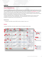
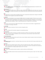
SOFTWARE VERSION 1.0
WWW.PRG.COM
VX76 BASIC PROFILE EDITOR
USER MANUAL
AutoPar®, Bad Boy®, PRG Series 400®, Mbox Extreme®, V476™, V676™, Virtuoso®, Virtuoso® DX, Virtuoso® DX2, and VL6C+™
are trademarks of Production Resource Group, LLC, registered in the U.S. and other countries.
All other brand names which may be mentioned in this manual are trademarks or registered trademarks of their respective companies.
This manual is for informational use only and is subject to change without notice. Please check www.prg.com for the latest version.
PRG assumes no responsibility or liability for any claims resulting from errors or inaccuracies that may appear in this manual.
Vx76 Basic Profile Editor User Manual
Version as of: June 6, 2011
PRG part number: 02.9814.2001.10
Production Resource Group
Dallas Office
8617 Ambassador Row, Suite 120
Dallas, Texas 75247
www.prg.com
Vx76 Basic Profile Editor User Manual
©2011 Production Resource Group, LLC. All Rights Reserved.
INTRODUCTION
About This Manual
This manual provides installation and operation instructions for the Vx76 Basic Profile Editor application. These
instructions apply to Vx76 Basic Profile Editor software version 1.0.
Familiarizing yourself with this information will help you get the most out of your PRG product.
Additional Documentation
For information on Vx76 equipment, refer to the following PRG manuals:
+ Vx76 Control Console User Manual (02.9814.0001.xx)
For more information regarding DMX512 systems, refer to the DMX512/1990 & AMX 192 Standards publication
available from United States Institute for Theatre Technology, Inc. (USITT).
USITT
6443 Ridings Road
Syracuse, NY 13206-1111 USA
1-800-93USITT
www.usitt.org
For more information regarding Art-Net protocol, refer to the specification for Art-Net II Ethernet Communication
Standard available from Artistic Licence Ltd.
Artistic Licence (UK) Ltd (Registered Office)
24 Forward Drive, Christchurch Avenue,
Harrow, Middlesex, HA3 8NT, United Kingdom
+44 (0)20 88 63 45 15 (phone)
+44 (0)20 84 26 05 51 (fax)
www.artisticlicence.com
For additional documentation, please visit our support tech center at: www.prg.com/support
VX76 BASIC PROFILE EDITOR USER MANUAL
1
Customer Service
For technical assistance, contact the PRG International Service Center or contact your nearest PRG office. Contact
information for all PRG office locations can be found on our website at: www.prg.com/about-us/locations/
PRG Dallas (International Service)
8617 Ambassador Row, Suite 120
Dallas, Texas 75247 USA
Phone: 214.630.1963
Fax: 214.630.5867
Service Fax: 214.638.2125
Service Email: [email protected]
For additional resources and documentation, please visit our website at: www.prg.com
2
VX76 BASIC PROFILE EDITOR USER MANUAL
OVERVIEW
About Vx76 Basic Profile Editor
The Vx76 Basic Profile Editor (BPE) is a fast and light tool that enables creation of simplistic profiles while in the field.
The BPE is not a replacement for fully sanctioned profiles, such as those provided in the console, and should only be
used in instances where there is not enough time for a profile request to be fulfilled by [email protected] or when an
uncommon or one-off profile is needed. Basic Profiles lack many of the advanced features found in Sanctioned
Profiles and are intended for basic control of a fixture. In some cases, it may be necessary to create and patch a Basic
Profile to be replaced later by a Sanctioned Profile once it is available.
The Basic Profile Editor exports "Profile Bundles," which are compressed collections of the necessary files to
complete an entire profile. These Profile Bundles can be imported directly into the console for patching, or
transported via portable drives, email, shared drives, etc.
Requirements:
+ The Basic Profile Editor requires OSX 10.6 (Snow Leopard) or later to run.
Interface
The Basic Profile Editor main screen contains controls for building the basic profiles.
VX76 BASIC PROFILE EDITOR USER MANUAL
3
Profile Name
1 The topmost bar is used to specify the unique name used to identify the profile throughout the console. Note that
no manufacturer is specified, as all Basic profiles are given the Manufacturer name of "Basic Profile" for
organizational purposes.
Name
2 This is the name of the profile as typically defined by the manufacturer (e.g., VL5, Bad Boy, Alpha Profile 1200,
etc.).
Option
3 This is the software configurable Option or Mode of the fixture. Sometimes this has a specific name, such as
Extended, Condensed, 16Bit, Extended Vector, etc. Often there is no name associated with the fixtures option, in
which case the channel count should be used, such as "9 Ch." This field is not required, but highly recommended
to avoid confusion with other profiles.
Short Name
4 This is an abbreviated name used to reference the profile thorough out the console when character space is
limited. A shortened version of the profile name is suggested here.
Intensity
5 This second bar is used to manage the Intensity channel and associated control information.
Address
6 This is the DMX address and bit size of the Intensity channel (if applicable).
Lamp Type
7 This is used to enable and disable special settings and options depending the intensity type of the fixture. In most
cases this choice should be rather obvious. If you are unable to determine the fixtures lamp type and the fixture
does indeed have a light output, it is suggested to choose "Other."
If a fixture has no intensity channel, choose "None" so that a phantom intensity channel may be added for the
purpose of cue data storage.
Control
8 When Arc, Tungsten, or Other are chosen for the Lamp Type, this section allows you to specify whether the fixture
has on-board intensity control or whether intensity is controlled via a separate control address (e.g., VL5). In the
case of the latter, the DMX address will blank out, as it will be specified separately when the profile is patched in
the console.
In the case of an LED fixture, this area specifies whether or not the fixture has a dedicated intensity channel (With
Intensity), or an inferred intensity by the combined state of the color channels (Without Intensity).
Add Parameter Button
9 Adds a new DMX channel to the end of the parameter list.
Remove Parameter Button
10 Removes the selected DMX channel from the list.
Export Profile Button
11 Once the profile is complete, press this button to begin the export process and create a portable Profile Bundle.
At this time the software will do a final profile validation and warn of any problems. Most problems must be
resolved before the profile will be exported.
Parameter List
12 List of DMX channels in order of address.
4
VX76 BASIC PROFILE EDITOR USER MANUAL
Parameter
13 A DMX channel, usually to be associated with a console Parameter. Selected Parameters are indicated in blue.
[13.1] [Img1Callout13.1]
DMX Address
14 The address of the DMX channel, sometimes called the DMX Offset. Changing this value amidst other values will
automatically re-arrange the parameters, and sometimes prompt the user to auto-increment following channels if
necessary.
Bits
15 Toggle button to selects whether the DMX channel is an 8 or 16 bit control. Note that non-contiguous 16 Bit DMX
channels are not supported by the Basic Profile Editor.
Parameter
16 Drop-down list allowing the user to assign the DMX channel to a console parameter. This will set not only what
encoder the channel is controlled by on the console, but also which filter group it belongs to in the function and
timing filters. Only one DMX channel can be assigned to each console parameter. If necessary, you can assign a
DMX channel to a parameter of "None," which will give the user no control over it in the console.
Label
17 The seven-character label of the DMX channel shown on the encoder and in the filters. A suggested label is
provided after choosing a Parameter.
Home Value
18 The DMX value the channel will "home" to when unchanged or reset.
Encoder
19 Area containing all of the encoder settings for the attached parameter.
Encoder Turns
20 Specifies the number of encoder turns it takes to go from the minimum to the maximum value of the DMX
channel. Different values are available for 8 and 16 bit channels, and indiscriminate values between those
provided are not available.
Reverse Orientation
21 Reverses the directionality of the encoder so that counter-clockwise rotation increases the value and clockwise
rotation decreases the value.
Wrap
22 Makes the encoder operate in a continuous loop so that once you reach the end of the range it starts back at the
opposite value.
Shortcuts
23 Assigns the seven-character label and value for the top and bottom encoder "defaults," allowing the user to
quickly recall a specific value within the encoder's range. Values must constrain to the bitrate of the encoder (0255 or 0-65535) with the added possible values of "min" and "max."
Attributes Panel
24 Contains extra information about the profile not directly related to the DMX footprint.
Shutter
25 Specifies the DMX channel and values to be associated with the console front panel's "Open" and "Close" shutter
buttons.
VX76 BASIC PROFILE EDITOR USER MANUAL
5
Icon
26 List specifying the icon used to represent the fixture in the Planview.
3D
27 Information related to the representation of the fixture in the 3D Graphic window.
Draw Distance
The distance, in feet, that the fixture's beam should render. Set this to a small number for LEDs used in an array
for a short-throw projecting effect.
Zoom Ratio
Ratio of the fixture's Zoom parameter. Expressed as a ratio, e.g., 8:1.
Beam Range
Degree range of the fixtures' Beam parameter from lowest to highest. If the fixture has no beam iris, set both
numbers to the fixture's lens angle.
Pan/Tilt Travel
Degree travel of the Pan and Tilt parameters, if applicable.
Pan/Tilt Orthog
The DMX value of Pan and Tilt parameters when the fixture is in its 50/50 position.
Model
List specifying the model used to represent the fixture in the 3D Graphic window.
Fixture Control
28 Contains the macro lists associated with the Lamp Start, Lamp Douse, and Fixture Reset functions available from
the console. Use these sections to create complex macros necessary to remotely strike, douse, and reset the
fixture over DMX. This often requires a number of values to be held for a period of time before the function will
execute on the fixture.
Add Event
29 Adds a DMX event to the end of the macro list.
Add Delay
30 Adds a Delay event to the end of the macro list.
Remove
31 Removes the selected event or delay from the macro list.
Event Channel
32 Sets the DMX channel that the value will be sent to.
Value
33 Sets the value to be sent to the DMX channel for events, or the number of seconds to delay before taking the next
event for a delay.
Note
34 Field for adding any pertinent information about the profile to be displayed when inspecting in the console's
fixture type picker.
6
VX76 BASIC PROFILE EDITOR USER MANUAL
Advanced
35 In the case where a fixture's assigned footprint is greater than the parameters defined (e.g., blank channels at the
end, timing channels, etc.) one can override the automatic channel count to make it larger. This is not
recommended unless it is absolutely necessary.
Note: You can only specify a channel number GREATER than the highest DMX address assigned in the Parameter
list.
Mod Date
36 The Date/Time stamp of the profile being edited. This is used to differentiate between older and newer versions of
profiles with the same name for profile upgrading purposes.
VX76 BASIC PROFILE EDITOR USER MANUAL
7
QUICK START
Creating a Basic Profile
Step 1. Begin by launching the Basic Profile Editor. It will create a new blank Basic Profile upon launch.
Step 2. Give the profile a unique name by filling in the "Profile Name," "Option," and "Short Name."
Note: It is best to sort out the intensity channel and modes first, as it will make the parameter auto-naming easier.
Step 3. Set the fixture’s lamp type, as well as how it is controlled, and enter the DMX address of the Intensity
channel if applicable.
Step 4. Add parameters to the list by pressing the green "Add Parameter" button on the bottom bar. Add as many
parameters as you will need to control the fixture. As you add parameters, each one will automatically
increment its DMX address.
Step 5. Once you have all of the parameters added, go through and set which parameters are 16-bit to fully space
out the footprint, matching the channels up with those in the documentation for the fixture. (e.g., Pan/Tilt,
Index, etc.).
Step 6. Now that you have the right number of parameters and all the DMX addresses and bits match up, start
assigning each channel to a Parameter by choosing one from the drop-down menu of parameters.
Assignment of parameters is up to the user, and it is not necessary to match up a parameter to its exact
name in the list. However, note that whatever parameter you map a channel to will set not only where the
encoder shows up on the front panel, but also what filter group it will belong to. While you can put a Color
control in the Beam, it will be controlled by the Beam group on the console.
Step 7. As you select parameters, a default label will be provided which may be changed if necessary. Labels are
limited to seven characters. A default Home value of 0 is applied to all new parameters, which will likely
need to be changed for some parameters (e.g., Pan & Tilt to 32768 if 16-bit, etc.).
Step 8. Each parameter is given a default encoder turn value, which changes automatically in the case of a 16-bit
channel. Many parameters also provide their own suggested shortcut labels and values. These may be
changed as necessary.
Step 9. Once the basic footprint is complete, start filling out the applicable information in the Attributes Panel on
the right. If the fixture has a shutter mechanism, set the DMX Channel and the open and closed values. Pick
an appropriate icon to represent the fixture in the planview. Many of the 3D settings can be left in their
default values, especially if the fixture is not a moving head, but it is likely that you will want to set the Zoom
Ratio and Beam Angle to better represent the fixture. As with the Icon, choose an appropriate model for the
profile to represent it in the 3D Graphic window.
Step 10. If the fixture has remote lamp strike, douse, or reset commands, create the macro events under the
appropriate header in the Fixture Control section. For example, let’s consider a fixture that has a control
channel on DMX address 8, with a Lamp Strike value of 127 that must be held for 3 seconds. Under Lamp
Start, add an event and a delay. Set the event's channel to 8, the value to 127, and the delay's value to 3
seconds.
Step 11. By now the profile should be completely filled out. To save the profile as a portable Profile Bundle, click the
Export Profile button on the bottom right. At this point, the profile will be validated, checking for any errors.
If errors are found, a dialogue will appear noting the issues, and most will highlight red in the interface.
Dismiss the errors, return to the application, resolve the problems noted, and try to export again.
The Basic Profile Editor exports "Profile Bundles," which are compressed collections of the necessary files to
complete an entire profile. These Profile Bundles can be imported directly into the console for patching, or
transported via portable drives, email, shared drives, etc.
If necessary, the Basic Profile Editor can edit previously created Basic Profiles to correct any errors that may have
been made or to use a Basic Profile as a starting point for another Basic Profile.
8
VX76 BASIC PROFILE EDITOR USER MANUAL
Vx76 Basic Profile Editor User Manual
Version as of: June 6, 2011
PRG part number: 02.9814.2001.10
Production Resource Group
Dallas Office
8617 Ambassador Row, Suite 120
Dallas, Texas 75247
www.prg.com