1
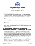
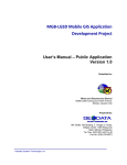
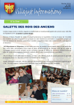
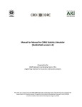
User’s Manual for Digitizing Maps using the CBMS‐NRDB April 2011 Prepared by the PEP‐CBMS Network Coordinating Team Angelo King Institute for Economic and Business Studies De La Salle University This work was carried out by the PEP‐CBMS Network Coordinating Team with the financial support of the Government of Canada provided through the International Development Research Centre (IDRC) and the Canadian International Development Agency (CIDA) User’s Manual for Digitizing Maps using the CBMS‐NRDB I. Introduction This manual contains guidelines and instructions on the use of the CBMS-NRDB software in digitizing maps for the CBMS Database1. The Community Based Monitoring System (CBMS) Database provides a facility for storing a wide array of information generated from the conduct of a CBMS Survey. One of its key features is that it can be used to generate desired information for presentation or reporting purposes in the form of maps aside from the tables and reports. It is a freeware originally intended for the use and maintenance of local government units (LGUs). The Database was customized for CBMS application using the Natural Resources Database (NRDB) and NRDB Pro2 as base software. The CBMS-NRDB Interface The database is intended to store CBMS survey results processed from the CBMS computerized data encoding system3 as well as other relevant data such as Administrative Boundaries (Barangays, Municipalities); Demography; Development Indices (Human Development Index, Human Poverty Index); Education and Literacy; Education Facilities; Employment; Health and Nutrition; Health Facilities; Income and Livelihood; Infrastructure and Utilities; Participation in Community Development; Security and Shelter; Water and Sanitation; Road Network; River Networks and others. The database can be expanded to accommodate other information that is relevant or may be needed by users at a particular point in time. Aside from the conventional way of viewing data in tables and charts, desired information from the database may be viewed in map format. A simple selection of preferred data or a more advanced query of desired information from the database can be generated in map, report and chart formats. Since socioeconomic and 1 Developed by the PEP-CBMS Network Coordinating Team of the Angelo King Institute for Economic and Business Studies The NRDB and NRDB Pro were originally developed by Richard Alexander. The CBMS Network Coordinating Team acknowledges the generosity of Mr. Alexander in sharing the software with the CBMS Team. His technical advice on the refinement of the NRDB for CBMS application is likewise acknowledged. 3 Refer to User’s Manual for the CBMS Computerized Data Encoding System for details. 2 2 political boundaries and other relevant parameters change over time, it is important to note that all information in the database has a date associated with it. Furthermore, since data contained in the CBMS Database is hierarchical, geographical or political relationships can be used for selecting data e.g. a barangay is part of a municipality, which is part of a province. Data can then be associated with the appropriate geographical location. Map 1. Proportion of households with access to sanitary toilet facilities, Labo, Camarines Norte, 2003. Source: CBMS Survey, 2003. The database is a stand-alone application. The data is held as a Microsoft Access database file, accessed through ODBC (Open Database Connectivity Standard). It is compatible with other software that facilitates importing of data directly from spreadsheets and from other databases. Moreover, map-based data can be imported from text files or shapefile format. Meanwhile, outputs can be exported back to spreadsheets or text files. A. Minimum Hardware and Software Requirements Compatible PC, Pentium Processor III or higher Minimum 256Mb Memory Windows 95 or above CD-ROM drive B. Data Requirements Each municipality in the province will be provided with a municipal CBMS-NRDB file (ex. Marilao.mdb), which have been prepared by the PEP-CBMS Network Coordinating Team. Each file already contains municipal and barangay boundaries, whenever available. Please note that the municipal shapefiles are official and the barangay shapefiles provided are sketch maps created by the National Statistics Office. In case a geo-referenced4 map from the National Mapping and Resource Information Authority (NAMRIA) is available at the municipality, the LGU can use it because this contains the official coordinates of the area. Details on how to use this is discussed in Section II.B. To create the needed features in the CBMS Database, the following are needed: 1. Barangay-level spotmap. The spotmap should contain the following: a. natural boundaries such as bodies of water (river, creeks, waterfalls, etc.), caves, hills, etc. b. historical landmarks, if any. c. Administrative boundaries (subvillage/purok boundaries etc) 4 Geo-reference refers to the geographic values found around the sheet edge. This provides the values of latitude and longitude at intervals. 3 d. Infrastructure such as road networks, bridges, railroads, schools, barangay halls, health centers etc. e. location of all households in the barangay, wherein each household have a unique household number. This household ID number should match the household ID number in the household profile questionnaire. f. Legend to indicate what are included in the spotmap. g. A north sign to indicate the direction of the map. Below is a sample map of Brgy. Bayanbayan, Labo, Camarines Norte. Sample map of Brgy. Bayanbayan, Labo, Camarines Norte, 2003 2. Corresponding complete list of names of household head per household indicated in the spot map of the barangay (to ensure that each household location corresponds to an accomplished CBMS household profile questionnaire). C. Installing the CBMS-NRDB software After inserting the Data source CD, a window will pop-up. Select CBMS-NRDB Mapping Tool and click the button Install. 4 Click Next to continue. After reading the CBMS license agreement, select the option “I accept the agreement” and click Next to continue. To start installation, Click Next. The setup for the NRDB will open, click Next. After reading the NRDB license agreement, select the option “I accept the agreement” and click Next to continue. Click Next to continue installing in the default folder C:\Program Files\Natural Resources Database. Users have the option to click browse to select another folder where the database will setup. Click Next to install the database in the folder. 5 Click Install to proceed installing the software. To complete the setup, click on Finish. As a default, the NRDB will automatically launch itself. Once installed, the database program will automatically open. The Login prompt appears. The Setup Process is complete. To re-open the database program, move the mouse to the bottom of the screen and click on the Start button, and then select Programs, Natural Resources Database and NRDB Pro button. II. Shapefiles Shapefiles consist of three types of data: 1) coordinates which represent a single point such as location of households, schools, barangay hall and other infrastructure; 2) polylines which may represent features such as rivers and road networks and; 3) polygons representing closed-area features such as municipal and barangay boundaries. Coordinates or points are entered either as latitude, longitude value or as Cartesian coordinates (x,y). Polylines and Polygons, on the other hand, are both series of coordinates. Whenever shapefiles are available, from different LGUs or NGAs, that the user can access, there is no need to digitize the shapefiles. In this case, it becomes redundant activity that may result in different versions of the same map. Existing shapefiles can be imported into CBMS-NRDB. A. Viewing existing shapefiles Open the NRDB program. To open your municipal CBMS-NRDB file in the log-in menu, Click Browse in the pull-down list and click the button open. 6 Go to the folder in the directory containing the access file containing the municipal database, for example, PadreGarcia.mdb and click Open. All CBMS text and nrdb files are found in the directory C:\CBMSDatabase and follows the Philippine Standard Geographic Codes in locating the regional-, provincial-, municipal- and barangaylevel files. For example, to locate PadreGarcia.mdb, the folder is located at C:\CBMSDatabase\04\10\20\CBMSNRDB\ Note: The Selection of the source database needs to be done only once. Next time, if you wish to access the database, you can connect directly. ) and To view the provincial map by municipality, click on the Map in the Main Menu (shortcut: click icon select Map Layers. The Map Layers window will appear. Click Add button. Select the FEATURE Municipality with the following specifications: Name: By default, all the municipal boundaries of the province of Batangas are highlighted. To view a specific municipality, highlight only the specific name of the municipality Display: Municipal boundaries (polylines/polygons) Label: Municipality (name) Double-click on the color box to select another color from the color palette. 7 Click Ok. In the Map Layers window, click Close and the map of the municipalities of Batangas will appear. To view the municipal map by barangay boundary, follow the same procedure as viewing the municipal boundaries. Click on Map in the Menu and select Map Layers. The Map Layers window will appear. Click Add button. Select the FEATURE Barangay with the following specifications: Name: <By default, all the barangay boundaries under the specified municipality are highlighted. To view a specific barangay, highlight only the specific name of the barangay > Display: Barangay boundaries (polylines/polygons) Label: Barangay (name) B. Utilizing existing shapefiles from other sources As the shapefiles included in the municipal NRDB files are sketch maps, if the LGU have available official shapefiles of their boundaries, then they can also use them. To do this, here are the steps: 1. Replacing a single shape a. Click Data, Edit Data… 8 b. At the top-most portion, select the Feature you wish to edit. Then select the specific name of the feature (For example, select the feature Municipality, then select the municipality Abucay). Click the button Edit Data… c. Another window will open. Highlight the cell where the data for the shapefile is located. In the CBMS-NRDB, the cell containing polygon or polylines data are colored blue. Click Import… button and select from the directory the shapefile that you want to use (Note: selected file should have extension name .shp). d. Click the button Open once you have selected the desired shapefile. 9 e. Afterwards, click Ok button and Close buttons to return to the main interface. 2. Replacing all the shapefiles a. Go to Data, Data Dictionary… b. Select the desired feature and click the button Delete… from the Delete Feature window, put a check besides Delete Data and press OK button. You will be asked if you are sure that the Feature is to be deleted. Click the button Yes. A window will appear indicating that the selected Feature has been deleted. Click OK. Then Click Close button in the Data dictionary window. c. From the file menu, select Import, Import, File... d. The Open dialog is displayed. Select the shapefile to be imported and click on Open. The Import dialog will be displayed. Click the pull-down list and select the Feature where the shapefile is to be imported. Click the button Select. The other half of the import dialogue will appear. The Import Columns contains the names of the headings (variable name) found in the shapefile. The Attributes contains the attributes belonging to selected Feature (ex. Municipality) as defined in the data dictionary of the database. e. Highlight the matching variables in the Import Columns and Attributes. For example, the variable Shapefile (polygons/polylines) in the Import Column is matched with the Barangay boundaries in the Attributes box while Barangay corresponds to Barangay [name]. Click the button Add to add the matched import column and attribute items to the Import box. When all the names have been matched, click Import. 10 f. The Import window will asked if you want to protect the shapefiles from being imported, skip this and click Next>> (you may need the shapefiles in the future as you can use this in other compatible software). g. You will be asked to encode the date. Default date is the current date. Click the button Next to start the importing data. h. The Import Status window will appear. Click the button Save to save the imported shapefiles. C. Digitizing maps (creating polygons, polylines and coordinates) If the needed shapefiles are not available from existing data sources, there is a need to digitize the shapefiles example: purok boundaries, location of household and other infrastructures found in the barangay. This activity merely translates the information from the paper spot map into the computerized database. 11 1. Digitizing polygons . a. In order to create a polygon, add the layer of the desired feature to digitize by clicking the Map Layer icon Select the desired feature with the corresponding display and label from the respective pull-down list. Click on the button OK to add the map layer. Click the button Yes when asked if you want to continue because no feature names have been selected. Example: To digitize the purok boundaries, click on the Map Layers with the following specifications: Name: <blank> Display: Purok boundaries (polylines/polygons) Label: Purok (name) Notice that there are no Purok names as there are no data of purok boundaries in the database. And as such, the user will be asked if he wants to continue because no feature names have been selected. Also, in the right hand of the interface, there is no colored square adjacent to the feature as normally seen from the other existing features in the database. Ensure that the desired feature that the user will digitize is bordered with a broken line, in this example, the feature Purok. b. To start digitizing, right-click on the desired area in the map and select Map, then select Add… c. The first time that the user will create a polygon, a window will appear to verify the type of shapefile he wants to digitize. A purok is a closed-area feature, thus, it is a polygon. Choose polygons and click OK. 12 d. The arrow cursor will become a cross cursor (). To create a new node, left click on a desired corner. To create the polygon, add more nodes as tracing the shape of the boundary. Please note that you are digitizing a polygon, which means that shape is automatically a closed-area. Press Del key (in the keyboard) to delete a node. Move left and right arrow keys (in the keyboard) to move between nodes. To facilitate more accurate digitizing, the user can also zoom in or out in the map by clicking the icons icon . To go to the full view of the province, click the icon . To pan around in the map, click the . Please note that the differently-colored node and line is only where the user may add or delete a node or a series of nodes. e. To save the created polygon, right-click and a window Add Name will appear prompting the user to add the name of the feature and select in which parent feature it belongs. Note: When digitizing, it is important to check if the digitized shapefile (whether polygon or coordinates) belong to the correct parent feature. In this example below, Bny_Purok1 belong to Barangay Banaybanay (parent feature). If the digitized barangay was wrongly placed in a municipality, go the specific Map, right-click on the desired area and select Data and Edit name. Click the pull-down list to select the appropriate parent feature where the shape really belongs. Click OK. f. Another window, Edit [feature], appears containing the name of the purok, the date when the shapefile (polygons) was digitized and the cell containing boundaries (blue-colored cell indicating the presence of a series of coordinates. Click OK to save the data. 13 2. Digitizing polylines a. To create polylines, which may represent features such as rivers and road networks, add the layer of the . Select the desired feature with the desired polylines feature to digitize by clicking the Map Layer icon corresponding display and label from the respective pull-down list. Click on the button Ok to add the map layer. Click the button yes when asked if you want to continue because no feature names have been selected. Example: To digitize the road network, click on the Map Layers with the following specifications: Name: <blank> Display: Barangay Road length (polylines/polygons) Label: Barangay Road [name] Select the desired feature with the corresponding display and label from the respective pull-down list. Click on the button Ok to add the map layer. Click the button yes when asked if you want to continue because no feature names have been selected. In the right hand of the interface, note that there is no colored square adjacent to the feature as normally seen from the other existing features in the database. Ensure that the desired feature that the user will digitize is bordered with a broken line, as shown the example below highlighting the feature Barangay Road. b. To start digitizing, right-click on the desired area in the map and select Map, then select Add… c. The first time that the user will create a polyline, a window will appear to verify the type of shapefile he wants to digitize. Choose polylines and click OK. 14 d. The arrow cursor will become a cross cursor (). To create a new node, left click on a desired corner. To create the polyline, add more nodes as tracing the shape of the road. Press Del key (in the keyboard) to delete a node. Move left and right arrow keys (in the keyboard) to move between nodes. To facilitate more accurate digitizing, the user can also zoom in or out in the map by clicking the icons province, click the icon . To pan around in the map, click the icon . To go to the full view of the . Please note that the differently-colored node and line is also where you may add or delete a node or a series of nodes. In some cases, road, river and other polylines features cross one another. It is recommended that different names of roads be made to refer to parallel or crossroads. Do not create crossroads within a feature name for easier management of shapefiles. e. To save the created polyline, right-click on the map and a window Add name will appear prompting the user to add the name of the feature and select in which parent feature belongs. f. Another window, Edit Barangay Road, should appear containing the name of the barangay, the date when the shapefile (polyline) was digitized and the blue-colored cell indicating that the lines are already contained in the database. Click OK to save the data. 15 3. Digitizing coordinates a. To digitize coordinates (such as location of households, schools, churches, barangay health center and other . Select the desired feature with the corresponding display and infrastructure), click the Map Layer icon label from the respective pull-down list. Click on the button OK to add the map layer. Click the Yes button when asked if you want to continue because no feature names have been selected. To digitize the household locations, click on the Map Layers with the following specifications: Name: <blank> Display: Household location (coordinates) Label: Household (name) The user can also observe that there are no household names and the user will be asked if he wants to continue because no feature names have been selected. Meanwhile, there are no colored square adjacent to the household feature in the right-hand corner of the interface. Before digitizing the location of households, go to the Map Menu, click Projections. Then uncheck the box adjacent to Display as Latitude /Longitude. Click update and close the Projection window. Always ensure that the desired feature to be digitized (example: household) is bordered with a broken line. Before digitizing coordinates, make sure that the parent features have already been digitized and defined. In the case of digitizing household locations, ensure that the purok boundaries have been digitized because the household is a child feature of the purok. b. To start digitizing a household, right-click on the map and select Map, then select Add. 16 c. The arrow cursor will become a cross cursor (). Click on the specific point in the map to add a coordinate. The Add Name window will appear prompting the user to input the household id number. Please note that this should be consistent with the household id number in the accomplished household profile questionnaire. d. The window Edit Household will then appear containing the name of the household (hh id no), the date when the shapefile (coordinate) was digitized and the actual coordinates. Click ok to save the data. Note: If you placed the point in the wrong spot, click the button Cancel in the Add Name window and start again. D. Editing existing sketch maps 1. Editing polygons a. In order to edit the boundaries of a barangay, be sure to select the feature you wish to edit. When a feature is selected, a broken line is visible around the name of the feature. b. When editing the digitized boundaries (example: purok), select the desired feature and click on the map (be sure that the desired feature is at the top layer of the interface. Right-Click on the map and a small window showing Data, Map and Report will appear. Click on Map and select Edit Lines. (Note that the Edit points option is disabled because you are editing a polygon/polyline and not coordinates.) c. Notice that the boundary now becomes a series of nodes with one of them differently-colored. Between this differently-colored node and another node, notice that the line is also differently-colored to guide the user where 17 to edit. You may add another node by clicking a desired spot to include that area. You may move the differentlycolored nodes and line with the left and right arrow keys in your keyboard. Zoom in or out to add more. d. When you have completed editing the map, right click to save the edited map. The user will be asked “Do you want to save changes?” Click Yes if you have correctly edited the map. To edit the barangay and purok boundaries or any other polygon, follow the same procedure as discussed above. 2. Editing polylines Editing polylines follows the same procedure as editing polygons. 3. Editing coordinates a. To edit a household point, first, ensure that the feature household is highlighted. Next, point the arrow into the dot and left-click to select Map and Edit points. b. Click on the dot and hold to transfer to the desired location of the household. Note: When many dots have been digitized, which distances are visible only when zoomed-in, editing coordinates using (a) and (b) procedure may not produce the desired results. Instead, go to Data in the main menu, click Edit Data. Choose the feature containing the coordinates the user wants to edit (example: Household). Select the corresponding name and click the button Delete. Then add the coordinate in the nearest estimated location possible. 18 E. Using scanned maps If at least two (2) opposing geo-reference points are known in the drawn spot maps, the spot map can be scanned using a desktop scanner. Scanned maps can then be geo-referenced and the data digitized on-screen. The CBMS-NRDB comes with a program Image to Shapefile, which can be used in using a scanned map to help in digitizing. 1. Open your NRDB file, e.g. SantaElena.mdb. In the Map layers dialog, click the button Overlay. 2. Browse and select the jpg or png file that will be used, for example, map of Santa Elena, Camarines Norte (SE_basemap.jpg). Click Open. 3. The Image to Shapefile will open and the map will be displayed on the screen. Left click on a point and enter enter its coordinates. In the example below, the coordinates of the 1st point have coordinates 14’15’N, 122,20E. Note: If the geo-reference entered was wrong, user can click button Delete and start over. 19 4. Click Close then add again the next point. This should be done for points where their coordinates can be identified e.g. the corners of the map. At least two opposing points should be selected. Using 4 points is ideal. The selected points will be displayed on the screen along with their coordinates. 5. When done, click Close. The scanned map will appear in the map layers, you can now digitize the shapefiles (refer to section II.C.). F. Using GPS5 The Global Positioning System (GPS) is a satellite-based navigation system made up of a network of 24 satellites placed into orbit by the U.S. Department of Defense. It was originally intended for military applications, but in the 1980s, the government made the system available for civilian use. It works in any weather conditions, anywhere in the world, 24 hours a day. There are no subscription fees or setup charges to use GPS. GPS satellites circle the earth twice a day in a very precise orbit and transmit signal information to earth. GPS receivers take this information and use triangulation to calculate the user's exact location. Essentially, the GPS receiver compares the time a signal was transmitted by a satellite with the time it was received. The time difference tells the GPS receiver how far away the satellite is. Now, with distance measurements from a few more satellites, the receiver can determine the user's position and display it on the unit's electronic map. GPS has a variety of applications on land, at sea and in the air. Basically, GPS is usable everywhere except where it's impossible to receive the signal such as inside most buildings, in caves and other subterranean locations, and underwater. For navigation For surveying For recreation For geology (measuring fault movements) For mapping For military applications Etc. A GPS receiver calculates its position by measuring the distance between itself and three or more GPS satellites. Measuring the time delay between transmission and reception of each GPS microwave signal gives the distance to each satellite, since the signal travels at a known speed. The signals also carry information about the satellites' location. 5 www.garmin.com 20 By determining the position of, and distance to, at least four satellites, the receiver can compute its position using trilateration. Receivers typically do not have perfectly accurate clocks and therefore track one or more additional satellites to correct the receiver's clock error. Sample of a GPS tracker To use GPS readings in the CBMS-NRDB project of an LGU, here are the steps: 1. Transfer GPS readings to excel 2. In the example above, Column C in the example shows the coordinates of the waypoints 3. Save the excel file at C:\CBMSDatabase\Regcode\Provcode\Muncode\CBMS-NRDB folder 4. Modify the columns as shown in the example below 5. Depending on the feature include several other columns needed such as barangay and municipality as parent features. When done the file can now be imported to the NRDB. 6. Open NRDB and Click File, Import, File 21 7. Open the saved excel file containing gps readings revised in steps 1-5 (ex. Nasipit schools) 8. The import window will open 9. Select the desired feature to put data into (ex. Elementary school) 10. Match the Import Columns with the Attributes by selecting at a time and Add Import Columns North East ---- Attributes Latitude Longitude 11. When all desired import columns and attributes have been matched and added, click import 12. Create the names of the features by clicking Create or Create All. 22 Create will prompt the user to create for every data it encounters Create All will prompt the user to create all data from the excel file 13. 14. 15. 16. Select the date (for uniformity, enter year of data creation) The import status will appear to show how many data was imported. Click the button Save to save the data Data can now be shown in the Map layers III. Saving the database As the program is a database, anything written or done in the database after digitizing and editing is automatically saved. 1. NRDB Map Lay-out Whenever the user wants to continue working using the same map layers with the same properties (such as color, legend, position of text and others), he/she may save the map lay-out in the computer as NRDB Map Layout (filename with .nrm extension). To illustrate this, save the sample file used in this manual, click the icon (or go to File, Save As…) and go to the desired directory to save the map lay-out. as sample.nrm. To open the file again, the user may double-click the file sample.nrm with icon in the directory. 23 THE PEP-CBMS NETWORK COORDINATING TEAM DR. CELIA M. REYES PEP Co-Director and CBMS Network Leader ANNE BERNADETTE E. MANDAP JASMINDA A. QUILITIS MARSMATH A. BARIS, JR ALELLIE B. SOBREVIÑAS JEREMY L. DE JESUS ERICA PAULA S. SIOSON NOVEE LOR C. LEYSO STEFFIE JOI I. CALUBAYAN JEFFREY G. ACERON Research Staff Inquiries regarding this CBMS work may be sent to: PEP-CBMS Network Coordinating Team Angelo King Institute for Economic and Business Studies 10th Floor Angelo King International Center Estrada Corner Arellano Avenue, Malate, Manila, Philippines 1004 Tel. No.: (632) 5262067; (632)524-8888 loc 274 Fax No.: (632) 5262067 E-mail: [email protected] [email protected] Website: www.pep-net.org 24