1
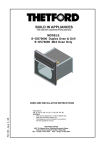
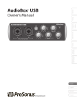
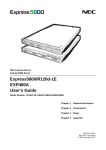
RevA 06-2013
USER MANUAL - ANDANTE ACTIVE SPEAKERS
Welcome
Thank you for choosing Hill Audio for your sound system. To make sure that this product meets your
expectations and provides long-term, reliable performance, please read and follow this instruction
manual carefully.
Manual Language
UK
FR
DE
ES
PT
IT
This user manual is written in English. For other languages, visit
Ce guide est écrit en anglais. Pour les autres langues, visitez:
Diese Anleitung ist in Englisch verfasst. Für andere Sprachen:
Este manual está escrito en Inglés. Para otros idiomas, visite:
Este manual está escrito em Inglês. Para outros idiomas, visite:
Questo manuale è scritto in inglese. Per altre lingue, visitare:
www.hill-audio.com
www.hill-audio.com
www.hill-audio.com
www.hill-audio.com
www.hill-audio.com
www.hill-audio.com
Important safety instructions
Read these instructions and all markings on the product. Keep these instructions.
Heed all warnings and instructions, both in this manual and on the product.
Clean only with a dry cloth. Unplug from AC supply before cleaning.
Do not use this product near water and avoid any exposure to water.
Before connecting this product to any AC supply, make sure to check whether the AC mains voltage and frequency match the indication on the product and its packaging.
Only connect this product to an AC supply with sufficient power handling, protective earth connection, ground-fault (earth-fault) protection and overload protection.
Disconnect the product from the AC supply during thunderstorms or longer periods of being
unused.
Make sure any heat sink or other cooling surface, or any air convection slot , is exposed sufficiently
to free air circulation and is not blocked.
Do not operate this product in environmental temperatures exceeding 35 degrees Celsius and/or
85% relative humidity.
Position the product in a safe and stable place for operation, out of reach of unauthorized persons.
Make sure any cable connections to and from the product are neither subject to potentially destructive mechanical impact nor present any risk of stumbling or other accident risk to people.
Audio equipment may generate sound pressure levels sufficient to cause permanent hearing
damage to persons. Always start up at low volume settings and avoid prolonged exposure to sound
pressure levels exceeding 90 dB.
Do not open this product for service purposes. There are no user-serviceable parts inside.
Warranty will be void in any case of unauthorized service by the user or other not authorized persons.
Take any precaution required by local law, applicable regulations or good business practice to avoid
injury of people or material damage by use of this product.
Explanation of symbols used in this manual and on the product:
ATTENTION!
Read manual
before installation
and operation.
PAGE 1
DANGER!
Safety hazard.
Risk of injury or death.
WARNING!
Hazardous voltage.
Risk of severe or fatal
electric shock.
WARNING!
Fire hazard.
USER MANUAL - ANDANTE ACTIVE SPEAKERS
Description
The Andante series is a series of lightweight, highly portable bi-amplified active PA speakers with an
extremely versatile feature set for a broad range of purposes including bands, mobile DJs, conferences and events. Using impact-resistant Polypropylene (PP) as the cabinet material and a highheadroom hybrid class AB + class D amplifier, these speakers are both robust in their handling and
powerful in their performance. Adding precision transducers, they offer great sound with superb
dynamics and the flexibility to adapt to any application from speech broadcasting to music replay,
whether live or pre-recorded.
The Andante series consists of three different models:
SMA1020: 10” | 2-way bi-amplified
SMA1220: 12” | 2-way bi-amplified
SMA1520: 15” | 2-way bi-amplified
The specifications for each model are available at the end of this user manual.
Setting up
A. Location
When choosing a location for the Andante speakers, keep the following in mind:
During transport or setup, avoid touching the cones of the loudspeakers with any object or with
your hands, as this could cause irreparable damage. Do not remove the protection grille.
Avoid pointing microphones in the direction of the speakers, as this could result in annoying feedback which can damage the speaker drivers.
B. Position
B1. On the floor
Andante speakers can either be positioned upright
(vertical) for general PA use or in a horizontal position for monitor use. Make sure that the floor is flat
and even to avoid the speaker to tumble. Avoid resonating floor positions for better sound.
Vertical
(general PA use)
Horizontal, 35° elevated
(monitor use)
B2. On a tripod.
The Andante speakers are equipped with a 1-3/8 inch (35mm) stand
mount, to allow mounting on tripod stands. Make sure that:
The speaker stand is certified of being capable of supporting the weight
of the speaker.
The speaker stand is placed on a flat, stable surface and the tripod legs
are fully extended.
The speaker stand legs and any cables are out of the way of any persons who may accidently trip over the stand or cables and pull the speaker
system over.
Before lifting the speaker onto the stand, be confident that you can handle
the weight safely and without injury to yourself, others, or damage to the
speaker.
PAGE 2
USER MANUAL - ANDANTE ACTIVE SPEAKERS
B3. Suspended from ceiling or truss (“Flown” installation).
DANGER - risk of injury: Flown installation requires extensive experience, like calculating
working load limits, knowledge of installation materials, and periodic safety inspection of all
installation material and the flown product. If you lack such qualifications, do not attempt
the installation yourself. Improper installation can result in injury of people.
As a preparation for flown installation, attach eyevbolts to the mounting points in the speaker cabinet
as per below drawing. In the further course of the installation, make sure that:
The product is installed out of reach of people and outside areas where persons may walk by or be
seated.
The installation area can hold a minimum point load of 10 times the device’s weight.
The installation is secured with an appropriate safety cable where necessary. Always use a certified
safety cable according to DIN56927 that can hold 12 times the weight of the device when installing
the unit. This secondary safety attachment should be installed in a way that no part of the installation
can drop more than 20cm if the main attachment fails.
The installation place is free from unwanted persons during installation, de-installation or servicing.
The safety-relating and machine-technical installations are approved by an expert before using
them for the first time.
The installation is re-inspected every year.
The cooling requirements are met (if any). Note that warm air is ascending, making the area below
a rooms’ ceiling potentially warmer than lower locations.
SMA1020
2xM8
2xBottom
SMA1520
5xM10
2xBottom
2xTop
1xRear
PAGE 3
SMA1220
4xM10
2xBottom
2xTop
USER MANUAL - ANDANTE ACTIVE SPEAKERS
Operation
User Interface
7
10 9 22
23
6
18
8
11
13
19
5
17
20
15
21
16
14
12
4
1
2
3
PAGE 4
USER MANUAL - ANDANTE ACTIVE SPEAKERS
Functional Description
Andante speakers offer a user interface which resembles a basic 3-channel mixer. While the main
input (CH1) is supposed to be a mono signal, the auxiliary inputs (CH2 and CH3) can be stereo signals,
of which it can be decided whether they are summed to mono and played by the internal speaker or
whether the left channel is played by the internal speaker and the right channel is sent to a 2nd
speaker. Various filter options and a possibility to connect a subwoofer are provided.
1
Voltage selector switch. The product shall be preset to the voltage of your location, but it is
recommended to check this before first operation. Available settings are 230V and 115V.
2
Power switch. Switches the product on and off.
3
AC inlet. Connect the supplied AC cord here.
4
Fuse holder. The fuse can be removed and exchanged by turning the holder and pulling out the
holder tray. Switch the unit off and disconnect the AC supply before doing so. Replace fuses
only with same value and rating. If the fuse blows a 2nd time, submit product for repair.
5
CH1 Audio input. This is an electronically balanced input which accepts either ¼’’ TRS plugs or
male XLR plugs.
6
Line/Mic sensitivity switch. Depending on the signal level supplied to the audio input (5), the
sensitivity can be selected between Line (released position) and Microphone (pressed position) level. If the output of the feeding source is unknown, set the sensitivity to Line first and try
whether the audio level is sufficient.
7
Ground lift switch. In case of a mismatch between ground potentials of this product and the
feeding source, this switch may help by making the audio signal ground “floating”.
8
High pass filter for input. Applies an 80Hz 2nd order high pass filter to the input signal. This
filter will most likely be used when the input signal comes from a microphone and the input
sensitivity (6) is switched to MIC. It helps to reduce low-frequency rumble which is easily picked
up by microphones due to handling noise. Do not use this function with a line signal if you
require full-range audio reproduction.
9
Signal level indicator (same for all three input channels). This is a 2-color LED red/white which
will illuminate its white element when the signal level is at -30dB. This is a good indication –
even when the volume is down – to see whether an input signal is present. The red element
will light up at 0dB indication that the recommended nominal internal level is reached. For best
dynamic headroom, it is recommended to not exceed this point.
10
Level control (same for all three input channels). Turning this control completely counterclockwise will reduce the respective signal to its minimum, while turning this control clockwise
increases the volume of the respective signal. Obey the signal level indicator (9) to not exceed
recommended nominal levels.
11
CH2 TRS Audio input. This is a 3.5mm TRS socket with switching contacts, meaning that once
any connector is inserted into this socket, the RCA input of CH2 (12) is disabled. The 3.5mm
TRS socket is ideal for mobile player sources. Note that depending on the link mode switch
(14), the stereo channels are either summed up to a mono signal and played by the internal
speaker, or the left channel of the source is played by the internal speaker and the right channel of the source is sent out via the Link connector (16).
PAGE 5
USER MANUAL - ANDANTE ACTIVE SPEAKERS
12
CH2 RCA Audio Input. This is a pair of RCA sockets to connect regular stereo audio equipment. Note that this input is disabled when a connector is inserted into the CH2 TRS audio
input (11). Also note that depending on the link mode switch (14), the stereo channels are
either summed up to a mono signal and played by the internal speaker, or the left channel of
the source is played by the internal speaker and the right channel of the source is sent out via
the Link connector (16).
13
CH3 TRS Audio input. This is a pair of ¼’’ TRS sockets, providing a balanced stereo input. The
right channel socket is a switching type; as long as no connector is inserted into the right channel, the right channel will automatically carry the left channel signal. If the signal connected to
this input is a mono signal, hence always insert this into the left channel socket. Note that
depending on the link mode switch (14), the stereo channels are either summed up to a mono
signal and played by the internal speaker, or the left channel of the source is played by the
internal speaker and the right channel of the source is sent out via the Link connector (16).
14
Link Mode switch. Depending on the setting of this switch, the signal presented on the Link
output (16) can either be the same as the mono sum of the internal channels, so that the
further speaker connected to the Link output (16) will carry the exact same signal; or it can
be set to carry the complementary stereo channel so that an external speaker connected to
the Link output (16) carries the right stereo channel while the internal speaker carries the left
stereo channel.
15
Link Frequency Range switch. Depending on the setting of this switch, the link output (16) may
either carry the same frequency range as the internal speaker or only the range up to 120Hz,
which would allow a subwoofer to be connected to the Link output without the need of an active
crossover.
16
Link output connector. This is a male XLR connector to supply a line-level balanced audio signal
to further Andante series speakers. Note that the signal carried by this output depends on the
settings of the Link Mode switch (14) and the Link Frequency Ranges switch (15), and refer to
the explanations provided there.
17
Thru output connector. Other than the Link Output (16), this male XLR connector supplies a
balanced signal exactly identical to the input signal connector to CH1. The main purpose is to
allow daisy-chaining of a number of Andante speakers, with every speaker receiving the same,
unprocessed signal.
18
Master Equalizer. This is a 2-band EQ, providing frequency response shaping to the mix of
channels 1/2/3.
19
Master Contour on/off switch. This switch determines whether a frequency response
contour filter is applied to the master signal or whether the master signal frequency response
stays flat. Once enabled, the choice of which contour filter is applied is made by the
Music/Speech Contour switch (20).
20
Music/Speech Contour switch. Once the master contour switch (19) is enabled, this switch
determines whether either a speech-adapted frequency contour filter (+8 dB 2khz-6kHz) or a
music “loudness” contour filter (+9 dB @ 55Hz / +4 dB @ 22.5kHz) is applied. The Speech
filter setting improves speech intelligibility but is less applicable to music replay, while the
Music filter setting is specifically designed for low-volume music replay where natural perception of low and high frequency presence is reduced. The music filter is not suitable for playing
music at medium or high levels; in such case all contour filters shall be disabled by means of
the master contour on/off switch (19).
PAGE 6
USER MANUAL - ANDANTE ACTIVE SPEAKERS
21
Output High Pass filter. This removes all frequencies below 120Hz with an 18dB roll-off from
the internal speaker. Main purpose is to remove low-frequency content when operating with
an additional subwoofer. This high-pass filter complements the low-pass filter (15) for the Link
output (16), so that the internal speaker does not carry content below 120Hz, while a
subwoofer connected to the Link output (16) carries all frequencies below 120Hz.
22
Power Amplifier Protection Indicator. This LED will come on when the internal power amplifier
limiter is engaged, indicating that the maximum system level is reached. Decrease the signal
level until the indicator is off.
23
Power indicator. This LED indicates whether the product is switched on or off.
Application examples
A. Applications using the internal mixer
Dynamic
Mic*
Audio Player
(stereo)
14
SPEAKER A
The function of SPEAKER B
will depend on the setting
of the Link Mode switch on
SPEAKER A:
14
* only dynamic microphones
are supported. No phantom
power for condenser mics
available.
Musical Instrument (mono or stereo)
Single speaker application for
street performances, product presentations, worship
Multiple speaker application for
conferences, entertainers, larger presentations
Link Mode Switch
MONO MIX (switch released): both speakers will
play the same mono mix
signal.
STEREO (switch pressed):
Speaker A will play the left
channel of the stereo mix
and speaker B will play the
right channel of the stereo
mix.
PAGE 7
SPEAKER B
USER MANUAL - ANDANTE ACTIVE SPEAKERS
B. Applications using an external mixer
Microphones
Audio Player
(stereo)
Musical Instrument
Audio
Mixer
SPEAKER A
14
15
21
SPEAKER B
Fullrange application for
conferences, fashion shows, background music
Satellite/Subwoofer application for
mobile DJs and bands
First Subwoofer
Second Subwoofer (optional)
Andante Speaker can be complemented with
subwoofers. In this application, the Link Mode
and Link Frequence Range switches, as well as
the Main Frequency Range switch need to be set
accordingly:
Link Mode Switch: Set to MONO
14
SUBWOOFER A
15
Link Frequency Range Switch:
Set to 120Hz LP
21
Main Frequency Range Switch:
Set to 120Hz HP
SUBWOOFER B
PAGE 8
USER MANUAL - ANDANTE ACTIVE SPEAKERS
Connections
The Andante series speakers use the below connector types, for which the pin assignment must
comply with the following specification. Always make sure to use good connectors and cables to
ensure proper operation. Balanced connections are to be preferred over unbalanced connections
where applicable and feasible. Avoid unbalanced connections exceeding 2m of cable length.
Balanced
connection
Unbalanced
connection
red = 2
black = 3
shield = 1
red = 2
shield = 1+3
red = 2
black = 3
shield = 1
red = 2
shield = 1+3
red = tip
shield = sleeve+ring
sleeve
red = tip
black = ring
shield = sleeve
red = tip
shield = sleeve
sleeve
red = tip
black = sleeve
shield = uncon.
red = tip
black = ring
shield = sleeve
red = tip
shield = sleeve+ring
red = tip
black = sleeve
shield = uncon.
red = tip
shield = sleeve
Structure
XLR male
2
3
1
plug
side
2
cable
side
3
cable
side
3
tip
ring
1
XLR female
1
3
2
1
3
2
plug
side
1
2
6.35mm TRS-stereo
ring
tip
sleeve
6.35mm TRS-mono
tip
tip
sleeve
3.5mm TRS-stereo
ring
tip
sleeve
tip
ring
sleeve
RCA
tip
sleeve
tip
sleeve
CABLE Types
shield
red
black
2-conductor shielded cable
(for balanced connections)
PAGE 9
red
shield
1-conductor shielded cable
(for unbalanced connections)
USER MANUAL - ANDANTE ACTIVE SPEAKERS
Technical Specifications
Model
SMA1020
SMA1220
SMA1520
LF driver
10'' with 2'' VC
12'' with 2.5'' VC
15'' with 2.5'' VC
HF driver
1''
1.35''
1.35''
LF amplifier
150W class D
250W class D
250W class D
HF amplifier
40W class AB
50W class AB
50W class AB
Amplifier protection
overtemperature
overtemperature
overtemperature
Power supply
switch mode
switch mode
switch mode
Frequency response 55 Hz-20kHz
50 Hz-20kHz
45 Hz-20kHz
Max. SPL
119dB
122dB
123dB
Dispersion
120° x 60°
120° x 60°
120° x 60°
Mounting points
2xM8
4xM10
5xM10
Dimensions WxHxD
321*503*291
385*596* 348mm
460*702*415mm
Weight
11.5 kg
14.0 kg
22.0 kg
Block Diagram
LINE
MIC
THRU OUT
GAIN
GREEN:
SIG-30
RED:
PK 0dB
HPF
@80Hz
12dB
IN1
EQ
GAIN
GREEN:
SIG-30
RED:
PK 0dB
CONTOUR
OFF
FLAT
MIX BUS L
HI
RED:
Peak
HPF
ON
ON
LO
SPEECH
HPF
@120Hz
18dB
IN2L
MUSIC
INTERNAL POWERAMP
Mono
IN2R
LPF
@120Hz
18dB
GAIN
GREEN:
SIG-30
RED:
PK 0dB
Sub
FQR
Subwoofer/FQ Range Switch
MIX BUS R
Mono
Stereo Position
IN3L
Stereo/Mono Link Switch
LINK OUT
IN3R
GND
LIFT
GREEN:
Power
PAGE 10
EC Declaration of Conformity
Manufacturer:
Address:
Adelto Technologies Limited
Vanguard Way, Shoeburyness, Essex SS3 9QY, UK
We declare on our own responsibility, that the equipment
Hill Audio Andante SMA1020
Hill Audio Andante SMA1220
Hill Audio Andante SMA1520
is in conformity with the following directives and standards or regulations:
EMC Directive 2004/108/EC
EN55103-1:2009 (Emissions)
EN55103-2:2009 (Immunity)
EN61000-3-2:2006 + A1:2009 + A2:2009
EN61000-3-3:2008
LVD Directive 2006/95/EC
EN60065:2002 A1:2006 + A11:2008 + A2:2010
ROHS Directive 2002/95/EC
and is marked as follows:
Shoeburyness, 28. June 2013
Place and date of issuing
Authorized Signature
www.hill-audio.com
Hill Audio products are developed, manufactured and distributed by
Adelto Technologies
Vanguard Way, Shoeburyness, Essex SS3 9QY, UK
www.adelto.com | [email protected]