1
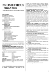
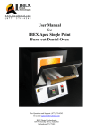
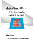
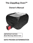
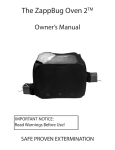
www.ibexdental.com
User Manual
Apex SP Burnout Dental Oven
IBEX Dental Technologies, Inc.
850 N. Dorothy Drive, #502
Richardson, TX 75081
877-370-4242
1
1 General ..................................................................................................................................................................................1
1.4 User Program heating/cooling rate unit .......................................................................................................................1
1.5 Options menu ..............................................................................................................................................................1
1.5.1 F/C Option .........................................................................................................................................................1
1.5.2 Thermocouple Offset .........................................................................................................................................1
1.5.3 CL t....................................................................................................................................................................1
1.5.4 CL d ...................................................................................................................................................................2
1.5.5 Lt t .....................................................................................................................................................................2
1.6 Ready to Cast programming ........................................................................................................................................2
1.7 Delay Start for Ready to Cast time ..............................................................................................................................3
1.7.1 Normal delay start .............................................................................................................................................4
1.8 Status Indicators ..........................................................................................................................................................4
1.8.1 LEDS .................................................................................................................................................................4
1.8.2 READY Display message .................................................................................................................................4
1.9 Indefinite Hold at Ready..............................................................................................................................................4
1.10 Deviation alarm (Open Door) ....................................................................................................................................4
1.11 Program Review ........................................................................................................................................................4
1.12 Dental Flow Chart .....................................................................................................................................................5
2 Program Operation….………………………………………………………………………………………………………..6
3 Error Messages……………………….………………………………………………………………………………………6
2
Initial Setup
Thank you for your purchase of the IBEX Apex Burnout Oven. Your Apex Burnout oven comes ready to plug in and program. The
only installation or setup would be the installation of the Floor Tray, pictured below. Due to the nature of the cast muffle, the floor
has a slight slant, or decline, from manufacture. The Floor Tray has a high temperature pad adhered to the underside of the Floor
Tray to raise the front end level with the back, also pictured below.
Floor Tray with Lift Pad attached.
3
Floor Tray installed.
1 General
1.1
User Program heating/cooling rate unit
The Heating and cooling rates for the Dental Oven will be programmed in units of Degrees per minute .
Range is 1 to 50° F/minute + (FULL) – Full On translates to approximately 76° F per minute from room temp to 1600° F.
1.1.1 F/C Option
Pressing the INCREASE button from the IdLE prompt will display the CHG option. This option is the same as the AF3000
controller to allow temperature units to be displayed in degrees Fahrenheit or Centigrade. CHG alternates on the display with the
default setting. Press increase button or decrease button to change the setting. Press PROGRAM to advance to the next option.
CHG Selections
F
C
Default setting
1.1.2 Thermocouple Offset
tCOS is currently available to the operator from the START prompt. This option shall be moved to the new option menu. The
operator can increase or decrease the temperature display in 1 degree increments. The default offset value is zero. The offset range
is increased from +/-20°F(11°C) to +/-180°F (100°C)
INCREASE/DECREASE buttons are used to set the TCOS. Press PROGRAM to advance to the next option
1.1.3 CL t
The controller should keep real-time with internal clock and calendar. Clock will not be battery back-up so if power is lost to the
controller, it will be necessary to reset the clock options.
Time will be a 24 hour clock 0000 – 2359 set by the operator. Default time is 1200. INCREASE/DECREASE buttons are used to
set the clock time. Press PROGRAM to advance to the next option. If power failure occurs, the clock time will reset to 1200
CL d
The controller should keep real-time with internal clock and calendar. Clock will not be battery back-up so if power is lost to the
controller, it will be necessary to reset the internal clock.
The Day is a 7 day calendar ranging Monday - Sunday
Monday – Sunday display codes as below
Monday
Tuesday
Wednesday
Thursday
Friday
Saturday
Sunday
_On
tUE
_Ed
tHU
FrI
SAt
SUn
INCREASE/DECREASE buttons are used to set the date. Press PROGRAM to advance to the next option.
If power failure occurs, the clock date will reset to Monday.
1
1.1.4 Lt t
The operator can program a safety limit temperature. This option appears only if the OEM option J3-2 is set for Safety relay.
If the limit temperature is detected during a firing, the controller will abort the firing with the display code OTL
1.2
Ready to Cast programming
The controller programming should allow the operator to program a ready to cast time and date. These program options will appear
at the end of the final hold segment HLD3.
After entering a value for HLD3, press the PROGRAM button to display CStd [Cast DATE] alternating with real-time clock date.
Operator uses the INCREASE/DECREASE buttons to set a ready to cast date.
NOTE: operator can check the real-time date is correct before setting a new cast date.
Press PROGRAM to advance to the TIME segment.
After entering a CStd, press the PROGRAM button to display CStt [Cast TIME] alternating with real-time clock time. Operator
uses the INCREASE/DECREASE buttons to set a ready to cast time for the cast date.
NOTE: operator can check the clock time is correct before setting a new cast time.
After entering the CStt, press the PROGRAM button to advance to the normal Strt [START] prompt.
To begin the new firing, press the PROGRAM button again to initiate the delayed firing.
Clarifications: The setting in option menu for date and time will allow the operator to set the actual date and time for the
controller. This time and date will need to be reset only if the controller power is lost. The operator must only set this time and date
option once if the controller will remain powered on indefinitely. Once the time and date is set by options, the controller is expected
to keep and update actual time as long as power is not interrupted.
In programming of the firing cycle, the operator will set a desired time and date for the firing to be at the READY stage. The
operator must program the 3 step firing cycle and then program a time and date for the controller to calculate when to start the
actual firing.
For example: The operator programs this firing cycle at 4PM (16.00) Monday afternoon.
Stage 1 20°F/min to 1000F - hold for 30 min
Stage 2 35°F/min to 1400F - hold for 30 min
Stage 3 50°F/min to 1500F - hold for 1 hour
Next, the controller offers the parameters for Casting time and date. This is the time the operator plans to come in the next morning
and have the burnout oven preheated and ready to load the product.
The controller will show CStt alternating with actual time [16.00]. The operator can adjust the cast time to 8AM the next morning
or [08.00]
The controller then offers the parameters for date. This is the day the operator plans to come in the next morning and have the
burnout oven preheated and ready to load the product.
The controller will show CStd alternating with actual day [_On]. The operator can adjust the cast day to Tuesday the next morning
or [TUE]
The controller then advances to the Strt prompt to begin the firing cycle at the calculated delay time.
1.3
Delay Start for Ready to Cast time
The controller must calculate from the firing schedule and from the programmed ready to cast time/date a delay start time.
The delay start time will be programmed automatically from the calculation.
2
Delay time should include
Program segment 1 ramp and hold time (adjusted for current burnout oven temp at start)
Program segment 2 ramp and hold time
Program segment 3 ramp and hold time
Time difference between current time/data and programmed ready time/date.
Clarification: When the operator presses the Start button from the Start prompt [Strt], the controller will determine or calculate the
necessary delay time to begin the firing.
For example: The operator programs this firing cycle at 4PM (16.00) Monday afternoon. To be Ready at 8AM on Tuesday.
1000F/hour to 1000F hold 1hour
500F/hour to 1400F hold 1 hour
300F/hour to 1500F hold 1 hour
the controller should calculate a delay start and begin a delay period. In the example program above, the delay would be calculated
with these values
Calculate Difference of cast time/date and actual time/date (Tuesday 0800 - Monday 16:00) = 16hours
Calculate the total firing time;
Ramp/hold stage 1 = (75F current TC start temp, .925hours ramp + 1hour hold) = 1.925 hours
Ramp/hold stage 2 = ( 0.800 hours ramp + 1 hour hold) = 1.800 hours
Ramp/hold stage 3 = (0.333 hours ramp + 1 hour hold) = 1.333 hours
Total time of firing = 5.058 hours
Calculate delay time by (time/date difference – firing time), (16 hours – 5.058 hours) = 10.942 hours
The controller would start at 4PM on Monday afternoon with delay time of 10.942 hours. This would allow the firing cycle to begin
at 3AM on Tuesday morning when the delay time expires. Then the firing will proceed for the next 5 hours and be ready at the
stage 3 cast temp at 8AM the same morning.
If the calculated delay time is equal to or less than zero, start the firing immediately with zero delay. For example, if the firing cycle
example above requires 5 hours but the operator has programmed a casting time and date of only 4 hours from actual time and date,
it is not possible to have the oven ready at cast temp in only 4 hours.
1.3.1 Normal delay start
The normal delay start that is accessed from the Strt prompt is no longer active.
1.4
Status Indicators
The controller LEDS will be used to identify the firing status.
1.4.1 LEDS
The dental oven will use the 3 discrete LEDs to show the progress of the firing program.
Top LED – on when the #1 ramp segment and hold is in progress or complete
Middle LED – on when the #2 ramp segment and hold is in progress or complete
Bottom LED - on when the #3 ramp segment and hold is in progress or complete
Note: the graphic overlay will identify the 3 LEDs from top to bottom as STAGE 1, STAGE 2, STAGE 3
1.4.2 READY Display message
When the burnout oven is ready to cast (ramp 3 hold segment is complete) the controller will toggle the message REdI and the
current burnout oven temperature. The onboard buzzer will beep for 30 seconds to announce the Ready condition.
3
1.5
Indefinite Hold at Ready
At the end of the program, the controller will hold the final hold temperature indefinitely. The operator must stop the controller
firing. During the indefinite hold period, the controller display will show REdI alternating with the current temp.
1.6
Deviation alarm (Open Door)
A new alarm is required for the temperature range 500 -800F. This alarm will be a safety shutdown in case of the burnout oven door
being left open during the firing. Note: if the door is left open, the burnout oven temperature is expected to stall near 650F.
The OPEn alarm aborts the burnout oven firing if the following 3 conditions are met for a duration of 10 seconds
1.
2.
3.
The burnout oven temp is between 500 – 800F.
The burnout oven temp is lagging the set-point by more than 50F
The output power to the heater relay is at 100%
If OPEn aborts the burnout oven firing, the display toggles OPEn and current burnout oven temperature. To clear the alarm display,
press any Button to return to Idle.
1.7
Program Review
The normal program review that advances directly to the start prompt from Idle is no longer active. Program review remains active
during the active firing. The discrete LED for program review is not active.
4
1.8
Dental Flow Chart
5
2 Ready to Cast Programming
Before programming, close furnace door. The controller must be set for the current day of the week and time.
(See instruction manual.)
(1) From IdLE, press START (the left button).
(2) Press the Up Arrow key (not the Down Arrow key) to select a program number. Press START.
(3) rA 1 will appear. Use the arrow keys to enter heating rate (temperature change per minute) for segment 1.
Press START.
(4) °F 1 or °C 1 will appear. Use the arrow keys to enter the target temperature for segment 1. Press START.
(5) HLd1 will appear. Use the arrow keys to enter the hold time of segment 1 (hours.minutes). (If not needed,
enter 00.00.) Press START.
(6) Continue entering values for the other 2 segments. Do you need fewer than 2 segments? When rA appears
for the next segment that you don’t need, select 0000. (This will zero out any remaining unused segments.)
Then press START.
(7) CL d will appear alternating with the current day of week. Use the arrow keys to select the day of week
when you will begin casting. Press START.
(8) Cstt will appear alternating with the current time. Enter the military time for the above day when you want
to begin casting (i.e. 8:00 a.m. = 08:00; 2:00 p.m. = 14.00).
(9) Press START. Strt will appear.
(10) Press START again. -On- will appear alternating with dELA and the number of hours and minutes
before the furnace will be ready for casting. To stop the furnace, press STOP (the left button) twice. STOP
will appear. Press STOP again to make IdLE appear.
3 Error Messages
4 bAdP / Bad Programming
The burnout oven will not fire because a) the Ramp-Hold program just entered has a rate of 0000 in segment
1, or b) the target temperature in Single-Speed or segment 1 of Ramp-Hold is lower than the current
temperature.
5 EtH / Electronics Too Hot
The circuit board temperature is above 176°F / 80°C. Press any key to return to IdLE .
To lower the board temperature, use a fan to blow air across the burnout oven switch box into the louvers.
(But do not blow air into the burnout oven’s peepholes.) If you have more than one burnout oven in the room,
place them farther apart. Never allow the firing room temperature to exceed 110°F / 43°C. (Measure room
temperature three feet away from the burnout oven.)
6 FAIL / Thermocouple Failure
The thermocouple, or temperature sensor, failed during firing. Causes:
Defective thermocouple or disconnected/loose wires
Defective controller
Electrical noise
Thermocouple Paperclip Test
Check the thermocouple wire connections. (See your burnout oven instruction manual.) If connections are
tight, perform this test:
1 UNPLUG the burnout oven or disconnect the power. Remove the controller. Remove the two thermocouple
wires from the back of the controller.
6
2 Cut a thin paperclip in half. Insert a U-shaped paperclip piece, or other piece of thin wire, where you
removed the thermocouple wires.
3 Plug in the burnout oven. FaIL will appear. Press START. Test results:
A) If the controller displays room temperature and IdLE after you press START, replace the thermocouple.
B) If the display still shows FaIL after you press START, return the controller for repair or replacement.
7 FE Error Messages
Message
Problem
FE 1 Memory Read/Write Failure
FE 2 RAM Failure
FE 3 OEM Factory Data Corruption
FE 4 Thermocouple “Noise”
FE 5 Software Error
To return to IdLE from an FE code
Try pressing any key. If that doesn’t work, turn the power off for 10 seconds. Call the factory if the error
message remains when you turn the power back on.
If you get an FE 4 message, check the wire connections going from the back of the controller to the
thermocouple. A loose connection can cause the FE 4 message.
8 FtL / Fired Too Long
This message appears when both of the following conditions are met:
The temperature rise or fall is less than 27°F / 15°C per hour.
The firing is 2 hours longer than programmed.
Programming a cooling segment target temperature that is below or even close to room temperature can also
trigger the FtL message.
See “Controller display turns on. No heat in burnout oven,” page 14.
Question: The controller on my Paragon SC-2 jewelry burnout oven flashes FtL , but only when I include a
controlled cooling. What is happening?
Answer: FtL means “firing too long.” But “firing too long” applies to cooling as well as to heating. FtL
can appear if you program a segment for slow cooling and the burnout oven is taking too long to cool.
Program a slower cooling rate. FtL will also appear if you program a cooling segment target temperature
that is below or close to room temperature.
9 HtdE / High Temperature Deviation
Causes:
During a heating-up ramp or a hold, the temperature is 100°F / 56°C above the programmed temperature.
During a cooling-down segment, the temperature is 100°F / 56°C higher than the segment’s starting
temperature.
A fast rate caused the controller to overshoot the target temperature.
Also, check for a stuck relay.
10 PF 1 / Power Failure
The power failed during a cooling segment, and the burnout oven cooled past the target temperature while the
power was off. The burnout oven will not resume firing. To return to the IdLE display, press any key.
11 PF 2 / Power Failure
The power failed during firing and burnout oven temperature was below 212°F / 100°C when the power came
back on. The burnout oven will not resume firing. To return to the IdLE display, press any key.
7
12 PF 3 / Power Failure
The power failed during firing and temperature dropped more than 72°F / 40°C by the time the power came
back on. The burnout oven will not resume firing. To return to the IdLE display, press any key.
13 tC / Thermocouple Failure
The thermocouple failed during the IdLE display. See the "paperclip" test under "FAIL," page 11.
14 tCL / Thermocouple Lag
The heating rate is slower than 9°F / 5°C per hour and the actual burnout oven temperature is more than
100°F / 56°C away from the programmed temperature. The tCL alarm becomes inactive above 500°F. To
return to the IdLE display, press any key. Causes:
Worn or burned out elements, defective relays, low voltage, and defective thermocouple.
On burnout ovens that use a portable controller, the thermocouple has fallen out of the firing chamber.
A bare spot on the thermocouple lead wires has touched a grounded object inside the burnout oven switch box
causing the thermocouple to short out.
You have programmed a cooling segment temperature that is below room temperature.
15 tCr / Thermocouple Reversed
This usually means the thermocouple lead wires are reversed. Check that the thermocouple lead wires are
connected to the correct terminals. See your burnout oven’s wiring diagram.
The thermocouple may be starting to fail and is sending erratic signals to the controller.
The thermocouple inside the burnout oven is much colder than the controller circuit board.
16 OPEN / Door Open
This error occurs if the door has been left open and the temperature has fallen below 800°F / 427°C for more
than 10 seconds while trying to heat up to or maintain a temperature above 800°F / 427°C. This error can
sometimes occur when high or full heat rates are used.
Trouble Shooter
17 Problem: Controller display is blank. No heat in burnout oven.
Is the burnout oven connected to the power?
Has the circuit breaker tripped or fuse blown?
Is power reaching the wall receptacle?
Test with a voltmeter or a test light if you are not sure.
Has the burnout oven switch box ½ amp fuse blown?
The burnout oven’s ½ amp fuse is located in the burnout oven switch box. Remove by pressing the fuse
holder and turning counter-clockwise half a turn. Check the fuse by placing the probes of an ohmmeter on the
ends of the fuse. If the ohmmeter reads less than an ohm (digital meter) or reads 0 ohms (analog meter), the
fuse is okay. If the reading is OPEN (digital meter) or infinity/no needle movement (analog meter), the fuse is
bad.
Replacement fuse:
AGC 1/2 A 250V AC
8
Is the controller receiving power? Test the power INPUT connections on the back of the controller with a
voltmeter.
Controller Power Input Test
Unplug the burnout oven. Remove the 4 screws holding the controller faceplate to the switch box. Lift
faceplate out of box and let the board hang on the box with the back of the board facing you. Plug the burnout
oven back in. Touch voltmeter probes (in AC mode) to both INPUT connections (the white and orange
wires).
Do not let the back of the board touch a grounded object. Make sure the voltmeter is in the AC mode when
placing the probes on INPUT connections.
Controller Power Input Test Result: No voltage
UNPLUG burnout oven. Check the switch box for disconnected wires between the cord, transformer, and
controller. If wiring is okay, replace the transformer.
Controller Power Input Test Result: 20 - 24 volts AC
Correct current is reaching the board from the transformer. But since the board is not lighting up, it is
probably defective. Return the controller for repair or replacement.
Controller Power Input Test Result: less than 20 volts
Did you recently replace the transformer? It may be the wrong voltage. The voltage is below 20, which is not
enough power for the controller. To find out the cause of low voltage, continue below:
Controller Input Test #2
The back of the board is still facing you and the burnout oven is plugged in. Remove the INPUT plug, which
is the white, orange, and blue wires, from the back of the controller. Touch a voltmeter probe to the white
wire and the other probe to the orange wire.
Input Test #2 Result: Less than 20 Volts AC
There are two possible reasons: 1) Low voltage at the wall receptacle; 2) defective transformer. If wall
receptacle voltage is correct, replace the transformer.
Input Test #2 Result: 20 - 24 Volts AC
The transformer is sending correct voltage to the controller. Yet when the INPUT plug was connected to the
controller, voltage was less than 20. This means the controller is draining the voltage and may be defective.
Return the controller for repair or replacement.
18 Problem: Controller display turns on. No heat in burnout oven.
Is the relay making its normal clicking sound?
Yes, the relay is clicking.
Test the elements with an ohmmeter:
Element Resistance Test
1 UNPLUG burnout oven/disconnect the power. Open the burnout oven’s switch box. Make sure the wires
connecting the relay to the elements are secure. If connections are okay, continue to step 2:
2 Touch the ohmmeter leads to the two element connectors of each element. A no-needle-movement reading
on an analog meter, or OPEN on a digital meter, indicates a broken element.
If the elements check out okay, replace the relay.
To replace relay, see your burnout oven’s instruction and service manual.
No, the relay is not clicking.
We know the controller is receiving voltage, because the display is lit. But the voltage from the transformer
may be too low to power the relays. Perform the “Controller Power Input Test,” page 13. If your controller
passes the Input Test, perform the “Controller Power Output Test”:
Controller Power Output Test
Is the controller sending voltage to the relay? Test OUTPUT with a voltmeter:
1 UNPLUG the burnout oven/disconnect the power. Remove the 4 screws holding the controller faceplate to
the switch box. Lift faceplate out of box and let the controller hang on the outside of the box with the back of
9
the board facing you. Then plug the burnout oven back in. Program the controller to fire to 1000°F at FULL
rate in Ramp-Hold mode. Press START.
2 Put the voltmeter in DC mode. (It must be in DC mode when testing OUTPUT voltage.) Touch probes to
the red wire and black wire connections. Measure the voltage when the relay clicks on.
Output Test Result: No voltage at red and black wires
The controller is not sending power to the relay. Return the controller for repair or replacement.
Output Test Result: 10 - 14 v. at red and black wires
The controller is sending correct power to the relay. Unplug burnout oven/disconnect power. Remove the
burnout oven switch box. Look for disconnected wires between the controller, relay and elements. Check the
wiring diagram to be sure wires are connected to the correct terminals. Be sure connections are tight. If the
wiring is okay, replace the relay.
To replace relay, see your burnout oven’s instruction and service manual.
19 Problem: Burnout oven switch box ½ amp fuses keep blowing.
What size fuse are you using? Correct fuse:
AGC ½ A 250V AC
If the fuse is the correct size, perform the following test:
Burnout oven Switch Box ½ Amp Fuse Power Test
1 UNPLUG the burnout oven/disconnect the power. Remove the 4 screws holding the controller board
faceplate to the switch box. Lift faceplate out of box and let the board hang on the outside of the box with the
back of the board facing you. Disconnect both wire plugs from the back of the controller. Then plug the
burnout oven back in. Apply power to burnout oven. If the ½ amp fuse blows, replace the transformer. (If the
fuse does not blow, the problem is a board or relay. Go to step 2.)
2 Connect the INPUT plug (orange, blue, and white wires) to the board again. Leave off the OUTPUT wire
plug (the one with the red and black wires). Program the controller to fire to 1000°F at FULL rate in RampHold mode. Press START. If the fuse blows, replace or service the board. (If the fuse does not blow, the
problem is caused by a short in the coil of a relay. Go to step 3.)
3 UNPLUG burnout oven/disconnect power. Reconnect the OUTPUT wire plug. Reinstall the board in the
switch box. Replace the relay.
20 Problem: The burnout oven over-fires.
Did you see an error message such as HTdE ?
If not, the thermocouple gave a faulty reading, so the controller did not shut off the burnout oven. Sometimes
a shelf can bump against the thermocouple and push it out of the firing chamber. Make sure the thermocouple
is pushed far enough into the firing chamber.
A 1/8” diameter thermocouple should extend into the firing chamber ½” - ”.
A ¼” diameter thermocouple should extend into the firing chamber 1” or more.
Keep shelves, posts and ware 1” - 1 ½” away from the thermocouple.
Do the elements stay on after you press STOP?
If so, the electrical contacts inside a relay are stuck in the closed position. This will also cause elements to
turn on as soon as you plug in the burnout oven. Replace the relay.
10