1
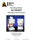
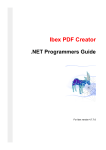
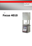
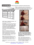
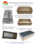
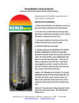
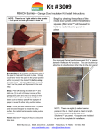
[Type text]
www.ibexdental.com
( 8 7 7 ) 3 7 0 - 4 2 4 2
User Manual
for
IBEX Apex Single Point
Burn-out Dental Oven
For Questions and Support: (877) 370-4242
Or e-mail [email protected]
IBEX Dental Technologies
850 N. Dorothy Drive, Suite 502
Richardson, TX 75081
Initial Setup
Thank you for your purchase of the IBEX Apex Burnout Oven. Your Apex Burnout oven comes ready to
plug in and use. The only installation or setup would be the installation of the Floor Tray, pictured below.
Due to the nature of the cast muffle, the floor has a slight slant or decline from manufacture. The Floor Tray
has a high temperature pad adhered to the underside of the Floor Tray to raise the front end level with the
back, also pictured below.
Floor Tray with Lift Pad attached.
Floor Tray installed.
2
Main Power Switch
Visual Alarm Indicator
Audible Alarm
Actual Temperature
Set Point Temperature
“Heater On” Indicator
Temperature “UP”
Set Point
Button
Placement Change
Temperature “DOWN”
3
General Information
Main Power Switch: This switch turns the power on to the oven. The control will perform a short self-test.
If no error are detected the oven will start heating up to the Set Point Temperature programmed in.
Audible Alarm Switch: This switch turns on or off the audible alarm. When this switch is on, a loud, fast
pulse beeping will be heard indicating that the oven has reached the programmed set point. To silence the
audible alarm, turn this switch off.
Operations and Programming the Temperature Set Point
The Apex SP Digital comes pre-programmed at 1600° and is set to display temperature in Fahrenheit.
Visual Alarm Indicator: This red indicator light will come on when the programmed Set Point temperature
has been reached.
Actual Temperature: The upper red digital display is the actual temperature inside the oven.
“Heater On” Indicator: This green indicator light comes on when the controller sends out a signal to turn on
the heating elements.
Set Point Temperature: The lower green digital display is the Set Point temperature programmed in by the
user.
Set Point Button: Pressing this button allows the user to change the set point temperature. Once pressed, the
upper display will show the letters “SP”. This confirms that you are in the Set Point program mode.
Temperature UP & DOWN Buttons: Use these buttons to lower or raise the desired Set Point temperature
to the new temperature. When finished, press the “SET” button again to exit the program mode.
A/M Placement Change Button: This button allows the user to change the Set Point temperature in tens or
hundreds by pressing the A/M button while in the Set Point program mode. If making a large temperature
change, using this button allows you to quickly change temperature by tens or hundreds.
4