1
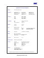
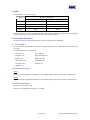
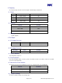
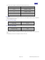
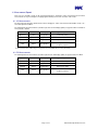
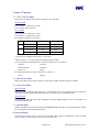
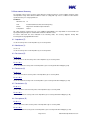
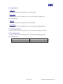
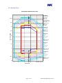
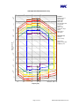
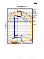
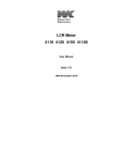
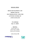
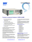
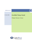
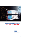
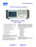
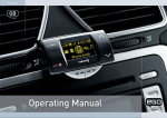
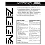
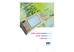
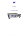
Wayne Kerr Electronics LCR Meter 4310 4320 4350 43100 Product Specification www.waynekerrtest.com UK – GLOBAL HQ Europe Wayne Kerr Electronics Wayne Kerr Europe GmbH Vinnetrow Business Park Märkische Str. 38 - 40 Vinnetrow Road 58675 Hemer Chichester Germany West Sussex PO20 1QH Tel: +44 (0)1243 792200 Tel: +49 (0) 2372 557 870 Fax: +44 (0)1243 792201 Fax: +49 (0) 2372 557 8790 Email: [email protected] E-mail: [email protected] Email: [email protected] USA China Wayne Kerr Electronics Inc. Wayne Kerr Asia 165L New Boston Street A604 Pengdu Building, Woburn MA 01801-1744 Guimiao Road, USA Nanshan District, Shenzhen, Guangdong China Tel: 781 938 8390 Tel: +86 138 2525 7230 Fax: 781 933 9523 Fax: +86 755 2652 3875 Email: [email protected] Email: [email protected] [email protected] Taiwan India Wayne Kerr Electronics Corporation Wayne Kerr Electronics Pvt Ltd No228-21, Sec 2, Bei Hsin Rd FF-73, Amrit Plaza Commercial Complex Hsin Tien City B Block, Surya Nagar Taipei 231 Ghaziabad (UP) Taiwan India Tel: +886 (2) 2915 8990 Tel: +91 (0) 12 0262 9612 Fax: +886 (2) 2915 5775 Fax: +91 (0) 12 0262 9613 E-mail: [email protected] E-mail: [email protected] Wayne Kerr Electronics 2011 The copyright in this work is vested in Wayne Kerr Electronics and this document is issued for the purpose only for which it is supplied. No licence is implied for the use of any patented feature. It must not be reproduced in whole or in part, or used for tendering or manufacturing purposes except under an agreement or with the consent in writing of and then only on the condition that this notice is included in any such reproduction. Information furnished is believed to be accurate but no liability in respect of any use of it is accepted by Wayne Kerr Electronics. www.waynekerrtest.com 4300 SPECIFICATION SUMMARY Models 4310, 4320, 4350 & 43100 Parameters Impedance (Z) Dissipation Factor (D) AC Resistance (R) Reactance (X) Phase Angle (A) Inductance (L) Conductance (G) Admittance (Y) Frequency 4310: 4320: 4350: 43100: 20Hz to 100kHz 20Hz to 200kHz 20Hz to 500kHz 20Hz to 1MHz Test Signal AC: DC: Source Impedance: 10mV to 2V (200 steps) 1V & 2V 100Ω ±1% DC Bias Internal: External: 2.0V ±5% ≤ ±40V Time Number of speeds: Fastest AC Time: Fastest DC Time: 4 12-17ms 72ms 119ms Range Impedance: 10.0000µΩ to >100.000GΩ Modes One or Two Test Mode Measurement , Limits-Scale & Operator Modes Save & Recall: 20 setups Accuracy Basic Accuracy: External Control GPIB, USB, LAN and RS232 General AC Input: Remote Control: Height: Width: Depth: Weight: Options /S1 (Scaleizer Type 1) /S2 (Scaleizer Type 2) /B1 (Bin Handler non-isolated) /B2 (Bin Handler isolated) Capacitance (C) Quality Factor (Q) Susceptance (B) DC Resistance (Rdc) From Trigger to EOM in Binning Total measurement time Total measurement time ±0.1% 90 to 264V AC auto ranging RS232, GPIB, LAN & USB 104mm (4.1”) 322mm (12.7”) 285mm (11.2”) 3kg (6.6lbs) Wayne Kerr Electronics Limited reserves the right to change this specification without notice. www.waynekerrtest.com 1. Models The 4300 range consists of four models: Measurement Frequency Model Minimum Maximum 4310 20Hz 100kHz 4320 20Hz 200kHz 4350 20Hz 500kHz 43100 20Hz 1MHz All instruments have a common specification with the exception of the maximum measurement frequency. Frequency step sizes are the same for each model up to the supported maximum frequency. 2. Measurement Parameters The 4300 can measure 11 different AC parameters and 1 dc parameter in any combination. 2.1. AC Parameters Series and parallel equivalent AC circuit models are supported which may be set independently for each test in Two Test mode. The following parameters are supported: Impedance (Z) Phase Angle (A) Capacitance (C) Dissipation Factor (D) Inductance (L) Quality Factor Q) AC Resistance (R) Conductance (G) Susceptance (B) Reactance (X) Admittance (Y) 2.2. AC Equivalent Circuit Series Any two series AC equivalent circuit parameters can be displayed at the same time as Function 1 and Function 2. Parallel Any two parallel AC equivalent circuit parameters can be displayed at the same time as Function 1 and Function 2. 2.3. DC Resistance (Rdc) Rdc can be set as Function 1 only. Function 2 is not available when Function 1 is set to Rdc. Page 4 of 18 4300 Product Specification Issue 4 3. Frequency The frequency range of the AC measurement signal is determined by the 4300 model. 3.1. Range Model Frequency Range Number of Frequency Points 4310 20Hz to 100kHz 557 4320 20Hz to 200kHz 577 4350 20Hz to 500kHz 637 43100 20Hz to 1MHz 737 3.2. Step Size Frequency Resolution 20Hz to 1kHz 5Hz 1kHz to 10kHz 50Hz 10kHz to 100kHz 500Hz 100kHz to 1MHz 5kHz 3.3. Accuracy ±0.005% (50ppm). 4. Test Signal 4.1. AC Voltage Drive Level Drive Range Detail Resolution 10mV to 2V into open circuit 10mV (200 steps) Drive Range Detail Resolution 1V or 2V into open circuit 1V (2 steps) 4.2. DC Voltage Drive Level 4.3. Source Impedance Source Impedance: 100Ω ±1% 4.4. Front Panel BNC’s Four front panel BNC (female) connectors provide a 4-terminal connection to the Device Under Test. The BNC screens are at ground potential. 4.5. Measurement Circuit Protection The 4300 measurement circuit can withstand connection of a charged capacitor up to following limits: Parameter Specification Voltage 50V to 500V Stored Energy <0.25J Polarity Both 4.6. Range Of Readings The 4300 can display readings in the following ranges. Page 5 of 18 4300 Product Specification Issue 4 The accuracy of these readings is specified in Section 9 Measurement Accuracy. Parameter Range R, Z , X 10.0000µΩ to >100.000GΩ G, Y, B 1.00000pS to >10.0000kS L 100.000pH to >100.000MH C 10.0000fF to >1.00000F D, Q 0.00001 to 99999.9 A -180.000 to +180.000 Rdc 0.1000mΩ to >10.000GΩ º º 5. DC Bias A DC bias voltage (derived from an internal or external source) can be applied to the Device Under Test (typically a capacitor) during AC measurements. 5.1. Internal DC Bias Voltage Parameter Specification DC bias voltage 2.0V ±5% Peak short circuit current ≤ 10mA 5.2. External DC Bias Voltage Parameter Specification Maximum bias voltage ≤ ±40V Peak short circuit current ≤ 225mA The bias voltage is obtained by connecting an external power supply to the bias terminals on the rear panel of the 4300. A resettable trip protects the bias circuit against a continuous short circuit. Page 6 of 18 4300 Product Specification Issue 4 6. Measurement Speed There are four selectable speeds for all measurement functions. Selecting a slower measurement speed reduces measurement noise by increasing the averaging applied and may increase the resolution of the results. 6.1. AC Measurements The fastest measurement time (defined as the time from trigger to end of measurement in bin handler mode) is 12 17ms with optimum conditions. The following total measurement times (includes keyboard scan and display update) are typical in One Test Mode for measurements > 850Hz. Speed Duration Averaging Suggested Application Maximum 72ms 1 acquisition Automatic sorting Fast 108ms 4 acquisitions Non-critical measurements Medium 253ms 8 acquisitions Improved resolution Slow 445ms 16 acquisitions Best accuracy & enhanced supply frequency rejection Total measurement times will be longer for frequencies less than 850Hz and also in Two Test Mode. 6.2. DC Measurements The following total measurement times (includes keyboard scan and display update) are typical in One Test Mode. Speed Duration Averaging Suggested Application Maximum 119ms 1 acquisition Automatic sorting Fast 312ms 4 acquisitions Non-critical measurements Medium 568ms 8 acquisitions Improved resolution Slow 1081ms 16 acquisitions Page 7 of 18 Best resolution & enhanced supply frequency rejection 4300 Product Specification Issue 4 7. Modes Of Operation 7.1. One & Two Test Modes Measurements are displayed in either One Test Mode or Two Test Mode. One Test Mode Test 1 (Function 1 & Function 2) is shown. Test 2 is turned off and not shown. Two Test Mode Test 1 (Function 1 & Function 2) is shown. Test 2 (Function 1 & Function 2) is shown. The following combinations are possible: Test 1 Function AC parameter DC resistance Function 1 Any Rdc Function 2 2 Function 1 Function 2 Any or Off (2) None (1) Any Any or Off Rdc (2) None (1) (1) Function 2 is not available when Function 1 is set to Rdc. (2) When Function 1 is set to an AC parameter Function 2 may be hidden. In Two Test Mode the following parameters can be varied between Test 1 and Test 2: Function 1 Function 2 Equivalent Circuit Frequency Drive Level Range The following parameters are kept the same in Test 1 and Test 2: Speed DC Bias 7.2. Measurement Mode Single and repetitive measurements of Function 1 and Function 2 in One Test Mode and Two Test Mode 7.3. Limits-Scale Mode One Test Mode Single and repetitive measurements of Function 1 and Function 2 and scale bar graphs. Each bar graph has configurable Hi/Lo limits giving a PASS/FAIL result and a visual indication of result relative to limits. Two Test Mode As Measurement Mode plus a table with configurable Hi/Lo limits giving PASS/FAIL result for each function and overall PASS/FAIL decision. 7.4. Operator Mode Single and repetitive measurements displayed with LOW/PASS/HIGH result (based on Limits-Scale Mode settings) for every function and overall PASS/FAIL decision. 8. Save and Recall 20 different measurement set-ups can be saved in non-volatile memory with user defined names. Any saved setup can be recalled. User defined names can be up to 10 characters long. Page 8 of 18 4300 Product Specification Issue 4 9. Measurement Accuracy The following sections and iso-accuracy charts define the specified accuracies over the available frequency range and impedance range under defined conditions. Failure to comply with any of these conditions means that the specified accuracy is no longer guaranteed. Conditions: AC Drive Level: 1V Trim: Instrument trimmed at measurement frequency Fixture: Wayne Kerr 1EV1006 Component Fixture Temperature: 23±5ºC AC supply frequency rejection may also cause additional unquantifiable errors dependant on measurement lead layout, particularly at frequencies below 600Hz and at lower AC Drive Levels. For above and below the areas indicated in the following charts, the accuracy degrades linearly with increasing/decreasing logarithmic DUT value. 9.1. Impedance (Z) Use the Z accuracy value on the Impedance (Z) Iso-accuracy Chart . 9.2. Admittance (Y) Use Z = 1/Y Use the Z accuracy value on the Impedance (Z) Iso-accuracy Chart 9.3. Resistance (R) For Q < 0.1 Use Z = R, then use the Z accuracy value on the Impedance (Z) Iso-accuracy Chart For 0.1 <Q< 1 Use Z = R, find the Z accuracy value on the Impedance (Z) Iso-accuracy Chart then multiply by (1+Q) 9.4. Reactance (X) For D < 0.1 Use Z = X then use the Z accuracy value on the Impedance (Z) Iso-accuracy Chart For 0.1 <D< 1 Use Z = X, find the Z accuracy value on the Impedance (Z) Iso-accuracy Chart then multiply by (1+1/D) 9.5. Conductance (G) For Q < 0.1 Use Z = 1/G then use the Z accuracy value on the Impedance (Z) Iso-accuracy Chart For 0.1 <Q< 1 Use Z = 1/G, find the Z accuracy value on the Impedance (Z) Iso-accuracy Chart then multiply by (1+Q) 9.6. Susceptance (B) For D < 0.1 Use Z = 1/B then use the Z accuracy value on the Impedance (Z) Iso-accuracy Chart For 0.1 <D< 1 Use Z = 1/B, find the Z accuracy value on the Impedance (Z) Iso-accuracy Chart then multiply by (1+1/D) Page 9 of 18 4300 Product Specification Issue 4 9.7. Capacitance (C) For D < 0.1 Use the C accuracy value on the Capacitance (C) Iso-accuracy Chart For 0.1 <D< 1 Find the C accuracy value on the Capacitance (C) Iso-accuracy Chart then multiply by (1+D) 9.8. Inductance (L) For Q > 10 Use the L accuracy value on the Inductance (L) Iso-accuracy Chart For 1 <Q< 10 Find the L accuracy value on the Inductance (L) Iso-accuracy Chart then multiply by (Q+1/Q) 9.9. D (Dissipation Factor) 2 Find the Z accuracy value on the Impedance (Z) Iso-accuracy Chart then multiply by (1+D )/100 9.10. Q (Quality Factor) Find the Z accuracy value on the Impedance (Z) Iso-accuracy Chart then multiply by (Q+1/Q) 9.11. Rdc Accuracy Resistance Range Accuracy 10Ω to 1MΩ ±0.2% Page 10 of 18 4300 Product Specification Issue 4 9.12. Accuracy Charts 4300 Impedance Measurement Accuracy Conditions: AC Drive Level: 1V Speed: SLOW DC Bias: Off Range: Auto Trim: 4300 trimmed at measurement frequency Fixture: 1006 Temperature range: 23±5°C Warm-up time: >30 minutes 10% 5% 100M 2% 1% 0.5% 10M 0.2% 0.1% 1M Impedance (Z): Use Z accuracy Admittance (Y): Z = 1/Y Use Z accuracy Impedance Z (Ω) 100k Resistance (R): For Q<0.1: Z=R Use Z accuracy 10k For 0.1<Q<1: Z=R Find Z accuracy then multiply by (1+Q) 1k Reactance (X): For D<0.1: Z=X Use Z accuracy 100 For 0.1<D<1: Z=X Find Z accuracy then multiply by (1+1/D) 10 0.1% 1 Conductance (G): For Q<0.1: Z = 1/G Use Z accuracy 0.2% 0.5% For 0.1<Q<1: Z = 1/G Find Z accuracy then multiply by (1+Q) 1% 100m 2% 5% 10m 10% 20 100 1K 10K Frequency (Hz) Page 11 of 18 100K 200K 500K 1M 4300 Product Specification Issue 4 4300 Capacitance Measurement Accuracy 0p 10 Conditions AC Drive Level: 1V Speed: SLOW DC Bias: Off Range: Auto Trim: 4300 trimmed at measurement frequency Fixture: 1006 Temperature range: 23±5°C Warm-up time: >30 minutes 10% 5% 2% 1n 1% 0.5% 0.2% 10 n 0.1% 0n 10 Capacitance (C): For D<0.1: Use C accuracy u 10 Capacitance (F) 1u For 0.1<D<1: Read C accuracy then multiply by (1+D) 0 10 u 1m m 10 0.1% 0.2% 0 10 m 0.5% 1% 2% 1F 5% 10% 20 100 1K 10K 100K 200K 500K 1M Frequency (Hz) Page 12 of 18 4300 Product Specification Issue 4 4300 Inductance Measurement Accuracy Conditions AC Drive Level: 1V Speed: SLOW DC Bias: Off Range: Auto Trim: 4300 trimmed at measurement frequency Fixture: 1006 Temperature range: 23±5°C Warm-up time: >30 minutes 10% 5% 2% 1% 10 0k 0.5% 0.2% 10 K 0.1% Inductance Value (H) 10 1k 0 Inductance (L) For Q>10: Use L accuracy 10 0m 1 10 For 1<Q<10: Find L accuracy then multiply by (Q+1/Q) 0.1% 10 m 0.2% 0.5% 1% 1m 2% 5% 10 0u 10% 20 100 1K 10K 100K 200K 500K 1M Frequency (Hz) Page 13 of 18 4300 Product Specification Issue 4 10. General 10.1. AC Input Parameter Specification Voltage 90 to 264V AC autoranging Frequency 45 to 63Hz Power 15W max Input fuse rating 1.6A T HRC (quantity 2) 10.2. Display 3.8” (96.5mm) ¼VGA 320 x 240 pixels. High contrast (adjustable) black and white LCD module with CPL back lighting. 10.3. Remote Control RS232C Connector: 9-pin female D-type Parameter Specification Baud rate 9600bps Character length 8bits Stop bit 1bit Parity Non-parity Character ASCII character GPIB Connector: 24-pin GPIB IEEE 488.1 bus standard and IEEE 488.2 code standard are supported. The command set has been designed to the SCPI 1992.0 standard. USB Connector: USB socket Type A USB 1.1 compatible. A USBTMC driver must be installed on the controller PC. LAN Connector: RJ45 (8P8C) Ethernet compatible with IEEE 802.3 and 10BASE-T PHY Remote Trigger (Trigger In) Rear panel BNC with internal pull-up, operates on logic low or contact closure. 10.4. Mechanical Parameter Specification Height 104mm (4.1") Width 322mm (12.7") Depth 285mm (11.2") Weight 3kg (6.6lbs) Page 14 of 18 4300 Product Specification Issue 4 10.5. Environmental Conditions This equipment is intended for indoor use only in a non-explosive and non-corrosive atmosphere. Temperature Range Parameter Specification Storage -40°C to +70°C Operating 0°C to 40°C Normal accuracy 18°C to 28°C (1) Relative Humidity Up to 80% non-condensing. Altitude Up to 2000m. Installation Category II in accordance with IEC664. Pollution Degree 2 (mainly non-conductive). Safety Complies with the requirements of EN61010-1. EMC Complies with EN61326 for emissions and immunity. Page 15 of 18 4300 Product Specification Issue 4 11. Options Only one internal option (S1, S2, B1 or B2) can be fitted to an instrument. 11.1. Scaleizer (S1 & S2) The Scaleizer module uses two relays (RL A and RL B) to provide two basic signals which indicate the PASS/FAIL decisions obtained in Limits-Scale Mode and Operator Mode. S1 Signals One Test Mode: RL A closes when Test 1 result is a PASS RL B is the inverse of RL A Two Test Mode RL A closes when both Test 1 and Test 2 results are a PASS RL B is the inverse of RL A S2 Signals One Test Mode: RL A closes when Test 1 result is a PASS RL B is the same as RL A Two Test Mode: RL A closes when Test 1 result is a PASS RL B closes when Test 2 result is a PASS Scaleizer (S1 & S2) Electrical Ratings Parameter Specification ≤50mA at 24V Output on-state current: 200mA total for all outputs Output off-state current: < 0.5mA Source/Sink impedance: 1Ω typical Trigger input high current: > 6mA 16V minimum Trigger input high voltage: 26.5V maximum Trigger input low current: < 0.5mA Trigger input low voltage: < 2V Maximum reverse voltage 48V (any input / output) Maximum voltage 48V between any pin and ground Page 16 of 18 4300 Product Specification Issue 4 11.2. Bin Handler (B1 & B2) The Bin Handler module provides binning signals based on user set limits in Binning Mode. Two Interface options are available. B1 Non-Isolated Interface Parameter Specification Output High Voltage: >4.0V Output Low Voltage: <1.0V Input High Voltage: >3.5V Input Low Voltage: <1.5V Current Capability Low: 10mA (sink) typical Current Capability High: 30µA (source) typical B2 Opto Isolated Interface Parameter Specification Output On-state Current: <10mA at 24V Output Off-state Current: <0.5mA Input Voltage: -1.5V at 10mA Input High Current: >3mA Input Low Current: <1.25mA Input High Voltage: >15.4V Input Low Voltage: <8V Page 17 of 18 4300 Product Specification Issue 4 12. Part Numbers 12.1. Models 4310 (100kHz LCR Meter) 1J4310R 4320 (200kHz LCR Meter) 1J4320R 4350 (500kHz LCR Meter) 1J4350R 43100 (1MHz LCR Meter) 1J43100R All instruments are supplied with the following items:User Manual 9H4300 Calibration Certificate QF110 USB Cable (Type A – Type A) HCUSBAA2M Kelvin Leads 1EVA40150 12.2. Options Only one option can be fitted per instrument. Scaleizer S1 Add /S1 Scaleizer S2 Add /S2 Bin Handler B1 Add /B1 4300 Bin Handler Manual also supplied Bin Handler B2 Add /B2 4300 Bin Handler Manual also supplied 12.3. Accessories SMD Tweezers 1EVA40120 Large Jaw Kelvin Clips 1EVA40180 1006 Component Fixture 1EV1006 Crocodile Clips 1EV1505 See www.waynekerrtest.com for a full list of accessories. Wayne Kerr Electronics Limited reserves the right to change this specification without notice. Page 18 of 18 4300 Product Specification Issue 4