1
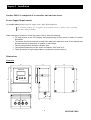
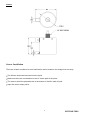
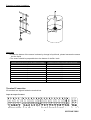
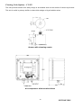
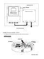
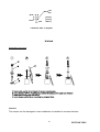
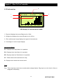
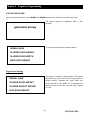
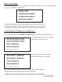
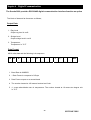
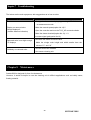
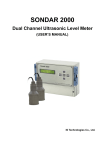
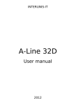
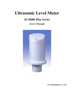
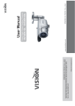
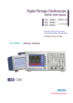
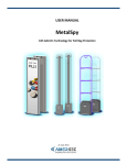
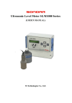
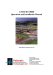
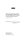
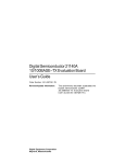
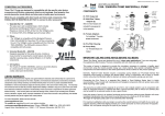
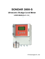
SONDAR 3000-S
Ultrasonic Sludge Level Meter
USER MANUAL V. 3.0
IS Technologies Co., Ltd.
SONDAR 3000
August 2003 Edition
COPYRIGHT
© IS Technologies Co., Ltd. All rights reserved. No part of this publication may be reproduced, transmitted, transcribed,
stored in a retrieval system, or translated into any language in any form without the written permission of IS Technologies
Co., Ltd.
WARRANTY AND LIABILITY
IS Technologies Co., Ltd. guarantees for a period of 1 year from the date of delivery that it will either exchange or repair any
part of this product returned to IS Technologies Co., Ltd. if it is found to be defective in material or workmanship, subject to
the defect not being due to unfair wear and tear, misuse, modification or alteration, accident, misapplication or negligence.
DISCLAIMER
IS Technologies neither gives nor implies any process guarantee for this product, and shall have no liability in respect of any
loss, injury or damage whatsoever arising out of the application or use of any product or circuit described herein.
Every effort has been made to ensure accuracy of this documentation, but IS Technologies cannot be held liable for any errors.
TECHNICAL ENQUIRIES
Please contact IS Technologies Co., Ltd. for technical support.
IS Technologies Co., Ltd.
203/504 Buchon Techno Park, 192, Yakdae Dong, Wonmi Gu, Buchon City Kyungki, Korea
Tel: 82-32-621 2606
Fax: 82-32-621 2612
Web Site: http://www.sondar.com
e-mail: [email protected]
2
SONDAR 3000
Contents
Chapter 1 Introduction……………………………………………………………….…………………….. ….4
About Sondar 3000..…………………………………………………….…………….………….. …4
Specification…………………………………………………………………...…………………....... 5
Chapter 2 Installation………………………………………………………………...……………………….…6
Power supply requirements………………………………………………..…………………………...6
Dimensions…………………………………………………………………….…………………….... ..7
Sensor installation………………… ………..…………………………………………………………..7
Terminal Connection………………………………………………………………………...…………. 8
Cleaning unit………………………………………………………………….………………………... 10
Skimmer protector
……………………………………………………………………………….…. 11
Chapter 3 How to use controller…….……………………………………………….…………………….... .14
LCD information….……………………………………………………………………………………..14
Button Function…………………………………………………………………………………………15
Chapter 4 Programming ………...…….…………………………………………………….…...…………… .17
Chapter 5 Engineer Programming..….……………………………………………..……………………….. .25
Chapter 6 Digital Communication……………….…………………………………………………………… 27
Chapter 7 Troubleshooting……….….….…………..……………………………………………………….…28
Chapter 8 Maintenance………………….……………………………………………….……………………. .28
.
Menu Record……………………………….…………………………………………………..…………………. 30
3
SONDAR 3000
Chapter 1 Introduction
About SONDAR 3000
The Sondar3000 is a highly developed ultrasonic level measurement system which provides
non-contacting sludge level measurement for a wide variety of applications.
The Sondar3000 measures and controls the solid/liquid interfaces in clarifiers, thickners,
settling tanks and other similar vessels.
It also provides a hinged swing bracket (“skimmer
protector”) that secures surface skimmer passage.
The graphic LCD display shows the echo profile as graphic image and the percentage of
current value of span with bar graph. The Sondar3000 applies not only wastewater treatment
plants (clarifiers) but also various slurry processes in most industries.
Some of the features of Sondar 3000 includes ;
* Simple calibration
* Various kinds of sludge applicable
* 2 programmable set point relays
* Rag & Sludge level display
* Auto sensor cleaning (option)
* Multi-points measurement up to 2 channels
4
SONDAR 3000
Product Specification
Physical
Dimensions
controller
sensor
mounting
weight
sensor material
Environmental
IP Rating (electronics housing)
Max. & Min. temperature (electronics)
Pressure
RTX cable length
192(Width). x 241(height) mm
Refer to the drawing
3/4 inch NPT
5.5kg
STS316
IP65 (Controller)
-20 ºC to +60 ºC (Controller), -20 to +70°C (Sensor)
up to 2 Bar
Max 100m (Consult with local engineer when extension is required)
Performance
Accuracy
Less than 1% at measured range or 2cm, which is greater.
Resolution
1mm
0~ 10 m ( Distance is 0.5m~10m)
Measuring range
Beam Angle
14o at -3dB.
Displayed value
Sludge Level, Rag Level, Percentage of Current Output, Relay status
Temperature Compensation
Fully compensated
Outputs
Analogue output
Setpoint Relay
Relay capacity
4-20mA into Max 600Ω (user adjustable) Fault condition Alarm 3.8mA /Hold/21mA
2 SPDT Relays
5A, AC250V
Programming
On-board programming
Supply
Power supply
via 5 tactile push button keys
AC 90 ~ 260V, Less than 15VA(50Hz ~ 60Hz), DC24V( Option )
5
SONDAR 3000
Chapter 2 Installation
Sondar 3000-S is composed of a controller unit and one sensor
Power Supply Requirements
The Sondar 3000 operates from a AC supply of 90 –260V, DC24V(Option)
All electronic products are susceptible to electrostatic shock, so follow proper grounding
procedures during installation.
When choosing a location to mount the sensor, bear in mind the following:
• For easy access to the LCD display and programming buttons mount it where it is easily
accessible.
• The sensor should be mounted at least 50cm above the maximum level of the material and
be perpendicular to the bottom of clarifier or tank sludge.
• The mounting surface should be vibration-free.
• The ambient temperature of the sensor is between -20ºC and 70ºC.
• There should be no high voltage cables or electrical inverters close by.
Dimensions
Controller
191
135
165
SONDAR 3000
220
241
Ultrasonic Sludge Level Meter
47
105
34.4
34.4
34.4
6
SONDAR 3000
Sensor
Sensor Installation
There are 4 basic conditions to avoid malfunction and to measure the sludge level correctly.
∗ The Sensor should be immersed into the liquid.
∗ Make sure there are no obstacles in the 14° beam path of the pulse.
∗ The sensor should be perpendicular to the bottom of clarifier/ tank of liquid
∗ Input the correct empty value.
7
SONDAR 3000
Examples of typical installation
Important
• In case the bottom of the sensor is shown by change in liquid level, please immerse the sensor
into the liquid
• The sensor should be perpendicular to the bottom of clarifier / tank.
Distance from the sensor to the surface of sludge
Distance from the wall of tank to the sensor
2m
3m
4m
5m
6m
7m
8m
9m
10m
70cm
100cm
130cm
160cm
190cm
210cm
240cm
270cm
300cm
Terminal Connection
25 terminals are aligned inside the terminal box.
Input & Output Terminal
SENSOR
RED BLK YEL WHT TEMP
DIGITAL
TX
RX GND
mA 1
+
-
mA 2
+
-
R1
R2
ER
NO COM NC NO COM NC NO COM NC
8
CLEAN
+
-
POWER
L
N
SONDAR 3000
Function
Terminal
①RED
②BLK
③YEL
④WHT
⑤TEMP
Function
SENSOR
Power supply
Ground
Operation signal
Signal reception
Temperature
Note
Red cable
Black cable
Yellow cable
White cable
Blue cable
DIGITAL
⑥TX
⑦RX
⑧GND
Transmission
Reception
Ground
RS232/485(Option)
RS232/485(Option)
RS232/485(Option)
⑨+
Rag Level current output(+)
⑩-
Rag Level current output(-)
⑪+
Sludge Level current output(+)
⑫-
Sludge Level current output(-)
⑬NO
Relay1 NO contact point. When the relay1 operates, NO and High Alarm
COM have a short circuit
User programming
Relay1 COM contact point. When the relay1 is in operation,
COM and CO have a short circuit. When the relay1 is not in
operation, COM and NC have a short circuit
mA 1
4~20mA outputs proportional
to Rag level
mA 2
4~20mA outputs proportional
to Sludge level
R1
⑭COM
⑮NC
Relay1 NC contact point. When relay1 is not in operation, NC
and COM have a short circuit
R2
16 NO
○
17 COM
○
18 NC
○
Relay2 NO contact point. When the relay2 is in operation, NO Low Alarm
and COM have a short circuit.
User programming
Relay2 COM contact point. When the relay2 is in operation,
COM and CO have a short circuit. When relay2 is not in
operation, COM and NC have a short circuit
Relay2 NC contact point. When the relay2 is in operation, NC
and COM have a short circuit.
ER
19 NO
○
20 COM
○
Error relay NO contact point. When the error relay is in Fault Alarm
operation, NO and COM have a short circuit.
User programming
Error relay COM contact point. When the error relay is in
operation, COM and CO have a short circuit. When the error
relay is not in operation, COM and NC have a short circuit.
21 NC
○
Error relay NC contact point. When error relay is not in
operation, NC and COM have a short circuit.
22 +
○
23 ○
Sensor cleaning
Sensor cleaning
CLEAN
Option
Option
POWER
24 L
○
25 N
○
AC power supply
AC power supply
9
SONDAR 3000
Cleaning Unit (Option) – CU412
This unit prevents sensor from sticky sludge or air bubbles stuck on the surface of sensor by air-blow.
This unit is useful in primary clarifier or where thick sludge or big air bubbles exists
Sensor with cleaning nozzle
Air compressor with terminal block
10
SONDAR 3000
Mounting Panel
min. 80mm
SONDAR 3000
SONDAR 3000 Cleaning Unit
Ultrasonic Sludge Level Meter
power inlet
air outlet
Panel Mounting
Skimmer Protector (Option) – SP413
Skimmer Protector protects the sensor from circulating skimmer
Installation Direction
Detail A
skimmer
skimmer
travel
11
SONDAR 3000
Mounting Details
mounting plate
(5t,STS plate)
U-block
U-bolt
sliding slot
consumer conduit
(20A,20S)
U-block
U-bolt
Detail A
120.0
40.0(adjustable)
60.0
(adjustable)
D 10.5
(adjustable)
10.0
(adjustable)
35.0
(adjustable)
230.0 250.0 405.0
62.5
o material : 5t, STS plate
Mounting plate
12
SONDAR 3000
R13.6+0.1
-0.0
25.0
29.0
16.4
50.0
o material : PVC or polymer
U-block
Assembling sequence
Caution!
The sensor can be damaged in case installation is installed in reverse direction
13
SONDAR 3000
Chapter 3 How To Use Controller
2
LCD information
1
R : 1. 5 0 m
36 %
S : 0. 9 0 m
4
3
0m
R1
R2
ER
DT
2.5 m
LCD display at measurement mode
1 : Rag level displays the current Rag Level in 0.01m
2 : Sludge level displays the current Sludge Level in 0.01m
3 : Echo oscilloscopic image displays the signal of returned echo
4 : Percentage of current output displays.
Operational Status
R1 : Displays when High Alarm is in operation
R2 : Displays when Low Alarm is in operation
ER : Displays when the Fault Alarm is in operation
DT : Flickers when the measurement is okay
S : Displays when search the returned echo
Term
Rag : This is light layer that forms normally above sludge blanket. Rag layer is so thin that it’s likely to
disappear occasionally.
14
SONDAR 3000
Button Function
MODE
SET
RUN
MODE Button
Press this button to enter into the program mode
SET Button
Press this button to change or save the set value
RUN Button
Press this button to enter into measurement mode
UP / Down Button
Press these buttons when change the set value at program mode
Pressing UP button at run mode shows enlarged scale, up to 10m.
<SET+DOWN> Button
Pressing SET/DOWN Buttons at the same time enters into temperature-distance mode as below picture
“D” represents distance from the sensor to the surface of sludge
T : +2 0. 0 C
D : 1. 6 0 m
0m
36 %
2.5m
Temperature-Distance Mode
15
SONDAR 3000
<UP+DOWN> Button
Pressing UP/DOWN Buttons at the same time enters into level-width.
2
1
L : 2. 00 v
W : 6 0 0 us
0m
36 %
2.5m
Level and Width mode
1 : Level of voltage of returned echo displays in 0.01V
2 : Width of time of returned echo displays in 1µs
Important
• After checking L and W, the threshold voltage can be adjusted at option menu No. 12.
• To measure the sludge correctly, the sludge echo height(L) should be lower than the set value of
SLUDGE ECHO HEIGHT at engineer mode. If the “S” shows continuously at measurement mode,
reset the sludge echo height at engineer mode.
• To measure the sludge correctly, the width of returned echo(W) should be lower than the set value
of SLUDGE ECHO BOUND at engineer mode. If the “S” shows continuously at measurement
mode, reset the SLUDGE ECHO BOUND value at engineer mode.( Refer to Chapter 5)
<SET+UP> Button
Pressing SET+UP buttons returns to run mode
MODE →SET → <MODE+DOWN> Button (Engineer Menu)
Pressing buttons in sequence as mentioned above enters into engineer menu mode.
16
SONDAR 3000
Chapter 4 Programming
Password Check
Factory Set= 0
PASSWORD CHECK
PASSWORD CHECK
PASSWORD ERROR!
PASSWORD OK!
RETURN MEASURE MODE
After pressing MODE button at measurement mode, the password checking is performed to prevent
disqualified person from misuse or malicious use. After pressing the preset number, operators can enter
the program mode by pressing SET button. If the password is wrong, the Sondar3000 automatically
return to run mode.
☞ (Mode→ UP or DOWN→Set )
Change Password
This option is for changing password.
*1. PASSWORD CHANGE
2. UNIT SELECTION
The password setting range is 0 ~ 1000.
• (Mode →Set→UP or DOWN→Set )
3. EMPTY
4. BLANKING
System Unit
FactorySet=Meter
1. PASSWORD CHANGE
*2. UNIT SELECTION
This option is for choosing system unit.
Operator can choose system unit between SI and US
unit. The minimum set value is 0.01m/0.1ft
3. EMPTY
4. BLANKING
17
SONDAR 3000
Bottom Set
FactorySet=5.00m
1. PASSWORD CHANGE
2. UNIT SELECTION
This option sets the maximum distance from the face of
the sensor to the empty point. The bottom (empty)
distance is important since all measurement is based on
this value
*3. EMPTY
4. BLANKING
Blanking Set
FactorySet=0.50m
1. PASSWORD CHANGE
This option is the distance from the face of the sensor
that is not capable of being measured, and is preset to
2. UNIT SELECTION
50cm. It should not be set less than this figure, but can
3. EMPTY
be increased if required. This option enables to ignore
*4. BLANKING
suspensions in the middle of the target material
4mA Point Set
Factory Set = 0.00m
This option sets the sludge level at which the 4mA output
*5. 4mA POINT
6. 20mA POINT
will occur. By default 4mA will represent Empty (0% of
Span). Use UP / DOWN button the set the value.
7. ALARM1 ON
8. ALARM1 OFF
18
SONDAR 3000
20mA Point Set
FactorySet=5.00m
5. 4mA POINT
*6. 20mA POINT
This option sets the level at which the 20mA output will
occur. By default 20mA will represent Full (100% of
Span). Use UP/DOWN bottom the set the value
7. ALARM1 ON
8. ALARM1 OFF
Alarm 1 On Set
FactorySet = 2.00m
This option determines the “ON” point for A1 relay. When
5. 4mA POINT
the measure value is over the set value Relay1 activates
6. 20mA POINT
*7. ALARM1 ON
8. ALARM1 OFF
Alarm 1 Off Set
FactorySet = 1.90m
This option determines the limit “OFF” point for A1 relay.
5. 4mA POINT
When the measure value is less the set value Relay 1
6. 20mA POINT
deactivates
7. ALARM1 ON
*8. ALARM1 OFF
19
SONDAR 3000
Alarm 2 On Set
FactorySet = 0.50m
*9. ALARM2 ON
10. ALARM2 OFF
This option determines the limit “ON” point for A2 relay.
When the measure value is over the set value Relay 2
activates
11. DAMPING RATE
12. TRANSMIT POWER
Alarm 2 Off Set
FactorySet = 0.60m
This option determines the “ OFF” point for A2 relay.
9. ALARM2 ON
*10. ALARM2 OFF
When the measure value is less the set value Relay 2
deactivates
11. DAMPING RATE
12. TRANSMIT POWER
Damping Rate
FactorySet = 2
This option determines the maximum rate at which the
9. ALARM2 ON
unit will respond to an increase/decrease in sludge level.
10. ALARM2 OFF
- Setting Range :
1 = 0.1m/min
2 = 0.5m/min
*11. DAMPING RATE
3 = 1m/min
12. TRANSMIT POWER
4 = 10m/min
20
SONDAR 3000
Transmit Power 1
FactorySet = 3
9. ALARM2 ON
10. ALARM2 OFF
11. DAMPING RATE
*12. TRANSMIT POWER 1
This option determines the transmitting power of the
ultrasonic pulse (Max. : 5, Min :1).
In arduous conditions decrease the TX POWER value for
accurate operations but unfavorable in long-range
measurement. Increase the TX POWER value in longrange measurements but vulnerable to ringing and
reverb ration.
Important
• Decrease the TX power value if there are obstacles in field. However, decreasing the TX power value
is not recommendable when long-range measurement requires.
• Increasing TX power may cause reverberation or multi-path signal. Need to check the application site
when increasing the power.
• Set option No.13 when the returned echo is not enough to detect.
Transmit Power 2
FactorySet = 20
This option determines the voltage value of sensor
*13. TRANSMIT POWER 2
14. DETECT THRESHOLD
15. FAIL SAFE CURRENT
transmission. Increase value in case the reception echo
is not enough to detect after choosing the highest value
at option12.TRANSMIT POWER 1. The set range is
1~100.
16. FAIL SAFE TIME
Important
• The supplied voltage range of sensor is V to 14V and the set value 0~100 is proportional to the
voltage
• Please be careful when use this option at noisy environment.
21
SONDAR 3000
Detect Threshold
FactorySet = 3
This option determines the detectable value of returned
13. TRANSMIT POWER2
echo. The set range is 1~12.
• (Mode→DOWN→Set→UP or DOWN→Set )
*14. DETECT THRESHOLD
15. FAIL SAFE CURRENT
16. FAIL SAFE TIME
Important
• In case the set value is high, it lessens measurement error. However, it may neglect weak returned
echo.
• In case the set value is low, it makes easy to detect weak returned echo. However, it may cause error
in noisy application. The below table is the voltage of each value
Threshold Value
Threshold Voltage
1
0.2
2
3
4
5
6
7
8
9
10
11
12
0.41 0.62 0.83 1.03 1.24 1.44 1.65 1.85 2.06 2.27 2.47
Fail Safe Current
FactorySet = HOLD
13. TRANSMIT POWER2
14. DETECT THRESHOLD
*15. FAIL SAFE CURRENT
If the Sondar 3000 fails to receive a valid echo returned
from the target, the current outputs to indicate a fault
condition (Lost of Echo). 3.8mA, 21mA or HOLD is
selectable at user’s need.
16. FAIL SAFE TIME
Fail Safe Time
FactorySet = 120s
13. TRANSMIT POWER2
In case of a fail-safe condition occurring (Lost of Echo)
the fail safe timer determines the time before the mA
14. DETECT THRESHOLD
output indicates a fault condition (Lost of Echo).
15. FAIL SAFE CURRENT
The set range is 20~999sec
*16. FAIL SAFE TIME
22
SONDAR 3000
Cleaning Cycle
FactorySet = 5s
If the sludge sediments or bubbles lay on the transducer
*17. CLEANING CYCLE
18. CLEANING TIME
19. 12mA OUTPUT 1
surface, it could lead to miscalculation. This option
determines the cleaning cycle when the cleaning unit is
in use. The set range is 0 ~10min. (Option)
20. 12mA OUTPUT 2
Cleaning Time
FactorySet = 5s
17. CLEANING CYCLE
This option determines the operation time of the sensor
cleaning. The set range is 0 ~ 100sec.
*18. CLEANING TIME
19. 12mA OUTPUT 1
20. 12mA OUTPUT 2
12mA Output 1
FactorySet = 200
This option outputs 12mA(Rag level) regardless of
17. CLEANING TIME
measurement. In case of failure, calibrate the current
18. CLEANING CYCLE
output 1 at Engineer mode.
*19. 12mA OUTPUT 1
20. 12mA OUTPUT 2
23
SONDAR 3000
12mA Output 2
17. CLEANING TIME
18. CLEANING CYCLE
This option outputs 12mA(Sludge level) regardless of
measurement. In case of failure, calibrate the current
output 2 at Engineer mode.
19. 12mA OUTPUT 1
*20. 12mA OUTPUT 2
24
SONDAR 3000
Chapter 5 Engineer Programming
ENGINEER MODE
At the programming menu, press MODE and DOWN buttons at the same time to enter this mode.
The below options is displayed after a few
seconds
@ENGINEER MODE@
To enter the Signal Gain, press set button.
SIGNAL GAIN
SLUDGE ECHO HEIGHT
SLUDGE ECHO WIDTH
RAG ECHO HEIGHT
Signal Gain Setting
This option is related to density factor. This option
determines the value that controls signal gain of
sludge density. Increase the value when the
sludge density is low. When “0” is displayed but
returned echo is not seen, set the value around
50~100.
*SIGNAL GAIN
SLUDGE ECHO HEIGHT
SLUDGE DETECT BOUND
RAG ECHO HEIGHT
25
SONDAR 3000
Sludge “L” & “W” Setting
At the programming menu, press MODE and UP buttons at the same time to enter this mode
These options determine the echo height and the
SIGNAL GAIN
width of returned sludge echo of threshold voltage
(option No. 13. DETECT THRESHOLD). These
*SLUDGE ECHO HEIGHT
options are for not only controlling potential noise
and disturbance, but compensating the factors
*SLUDGE DETECT BOUND
according to field condition and kinds of sludge.
RAG ECHO HEIGHT
The below picture explain the terms of echo height
and echo bound.
L : 2. 00 v
W : 6 0 0 us
36 %
Echo height
Echo width
Threshold
0m
2.5m
Example of option setting
In case “L” is 2.00V, the set range of sludge echo height should be around 0 ~ 2.00V.
In case “W” is 600µs, the set range of sludge echo width should be around 0 ~ 0.60ms.
Important
In real application, the “L” and “W” depend on the field condition and kinds of sludge. The factory setting
value is “0”.
Please consult with us when setting this option.
26
SONDAR 3000
Rag “L” & “W” Setting
These options determine the echo height and the width of returned rag echo of threshold voltage
(option No. 13. DETECT THRESHOLD)
SIGNAL GAIN
SLUDGE ECHO HEIGHT
SLUDGE ECHO WIDTH
*RAG ECHO HEIGHT
The RAG ECHO HEIGHT (LOW) option determines the low value of echo bound.
The RAG ECHO HEIGHT (HIGH) option determines the high value of echo bound
* Generally the rag layer is so thin that it’s easy to disappear in normal application.
Current Calibration 1&2 (Rag Level & Sludge Level)
At the programming menu, press MODE and DOWN buttons at the same time to enter this mode.
Connect the terminal mA1 +/- to an ammeter
RAG ECHO WIDTH (LOW)
Press SET button to select 12mA
RAG ECHO WIDTH (HIGH)
*12mA Calibration1
*20mA Calibration1
4mA Calibration1
Check if 12mA outputs from an ammeter.
RAG DETECT LOWER BD
Press UP/Down buttons for calibration
RAG DETECT UPPER BD
12mA Calibration1
20mA Calibration1
4mA Calibration1
After 12mA calibration, choose 20mA and then do the same as 12mA calibration
The 4mA will output correctly after calibrating 12mA and 20mA.
* Sludge level mA calibration is the same as that of rag level ( Calibration2 )
27
SONDAR 3000
Chapter 6 Digital Communication
The Sondar3000 provides RS232/485 digital communication interface function as option
The kinds of data and its format are as follows;
Output Data
1. Rag Level
Output rag level in cm/ft
2. Sludge Level
Output sludge level in cm/ft
3. Temperature
Temperature in °C/°F
Data Format
ASCII edits data and the following is its sequence
CR
LF
R
S
100 10
1
T
100
10
1
+,-
NUL
10
1
1. Baud Rate is 4800BPS
2. 1 Data Frame is composed of 15byte
3. Data Frame outputs on a second basis
4. The number located at 100 means hundred cm/ft unit.
5. +/- mean above/below zero in temperature. The number located at 10 means ten degree unit
in °C/°F
28
SONDAR 3000
Chapter 7 Troubleshooting
The below are the main symptoms, with suggestions as to how to solve
Symptom
Solution
• Change the distance in display by pressing UP/DOWN button
at measurement mode
Display no returned echo
Sludge displays 0
( bottom distance indication)
• Make the transmit power(option No.12) 5
• Open the controller and turn the TVG_VR counterclockwise
• Make the detect threshold(option No.13) 1~3
• Increase signal gain(option No.18)
Returned echo is not high enough
“S” displays
• Decrease the detect threshold value
• Make the sludge echo height and width smaller than the
values of “L” and “W”
Suddenly no returned echo
Chapter 8
• Use the above two methods
• Use sensor cleaning unit
Maintenance
Sondar3000 is designed for free of maintenance.
However, it would be helpful to use the cleaning unit in difficult applications such as bubbly water,
floating material.
29
SONDAR 3000
Menu Option Record
SONDAR 3000
Option Details
Entered Value
No.
Description
Factory Set
Value Range
01
Password Change
0
0 ~ 1000
02
Unit Selection
Meter
Meter/Feet
03
Empty
5.00m/16.4ft
04
Blanking
0.50m/1.7ft
0 ~ 10.00m/32.8ft
05
4mA SetPoint
0.00m/0ft
0 ~ 10.00m/32.8ft
06
20mA SetPoint
5.00m/16.4ft
0 ~ 10.00m/32.8ft
07
Alarm1 On
2.00m/6.6ft
0 ~ 10.00m/32.8ft
08
Alarm1 Off
1.90m/6.2ft
0 ~ 10.00m/32.8ft
09
Alarm2 On
0.50m/1.7ft
0 ~ 10.00m/32.8ft
10
Alarm2 Off
0.60m/2.0ft
0 ~ 10.00m/32.8ft
11
Overlap Weighting
80%
0 ~ 100%
12
Transmit Power 1
3
1~5
13
Transmit Power 2
20
1 ~ 100
14
Detect Threshold
3
1 ~ 10
15
Fail Safe Current
Hold
3.8mA/Hold/21mA
16
Fail Safe Time
120
20 ~999
17
Cleaning Cycle
Off
0 ~ 100min
18
Cleaning Time
5
0 ~ 100sec
19
12mA Output1
20
12mA Output2
1
2
3
0 ~ 10.00m/32.8ft
30
SONDAR 3000
4