1
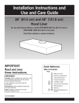
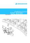
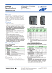
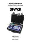
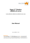
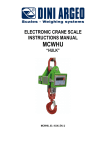
WEIGHING INDICATOR / REPEATER
SERIE IPE 50
User manual 1/2
For calibration and basic function
See user manual 2/2 for special functionning mode and output RS232/485, this manual is available on our
Web site www.scaime.com
SUPPORT -> product documentation -> product-user-manuals -> NU-IPE50-2-E-….
(valid from version 06.01)
SCAIME SAS
BP501
74105 ANNEMASSE France
Tél : 33 4 50 87 78 64
Fax : 33 4 50 87 78 46
www.scaime.com
INDEX
1 INTRODUCTION
P3
2 MAIN TECHNICAL SPECIFICATIONS
P4
3 DIMENSIONS
P5
4 POWER SUPPLY & START-UP
P8
5 FRONT PANEL KEYS AND INDICATORS
P8
6 BASIC FUNCTIONS
P10
7 SELECTABLE OPERATING MODES
7.5 Setpoint adjustment
P10
P11
8 INSTRUMENT MESSAGES WHILE IN USE
P15
9 INSTALLATION
P16
10 BLOCK DIAGRAM
P17
11 SETUP
P20
12 ADJUSTMENT
P26
13 ANALOG OUTPUT
P31
14 ERROR MESSAGES
P32
2
1 INTRODUCTION
The purpose of this manual is to help the user get to know the weight indicator’s various functioning modes,
the keys’ functions and the display indications
We advise to carefully follow the instructions for programming the weight indicator; by taking actions
not indicated this manual, one could cause the scale to not work properly.
In addition to having all the characteristics of a high precision scale, the indicator has the kg/lb conversion
function, the gross weight / net weight conversion, set point on gross weight or net weight, in/out weigh,
repeater in r.f. transmission, alibi memory, hold function, peak detector, weighs totaliser and piece counter.
The indicator adapts to normal weighing applications in either industrial settings, such as during factory
production processes, or that of commerce, such as legal for trade applications, also satisfying the frequently
needed ability to transmit and print the data through its two bidirectional serial ports.
This manual has been made as carefully and exactly as possible; in any case, your suggestions are
always welcome.
WARNING
Any attempt to repair or alter the unit can expose the user to the danger of electric shock and it will void our
warranty. This instrument is covered under warranty provided that IT HAS NOT BEEN OPENED BY THE
USER for any reason. If any problem with the unit or system has been experienced please notify the
manufacturer or the dealer from which the instrument was acquired.
Do not pour liquids on the indicator!
Do not use solvents to clean the indicator!
Do not expose instrument to either direct sun light or any heat sources!
Always mount the indicator and platform in a vibration free setting!
Read carefully & apply what described in the POWER SUPPLY & START-UP section!
Do not install in an environment with any risk of explosion!
3
2. MAIN TECHNICAL SPECIFICATIONS
POWER SUPPLY
12 to 24Vdc / 3.6 W max (110/220Vac for IPE50XLR)
OPERATING TEMPERATURE From -10 to +40 °C (14 to 104 °F).
DISPLAYED DIVISIONS
10000e, 2X3000e for legal for trade use expandable to 800.000 for internal use
(with minimum signal coming from the 1,6mV/V cell).
RESOLUTION IN CALCULATION 150'000 points (with signal in input equal to 3mV/V).
MAX INPUT
+ 30mV (+ 6mV/V)
DISPLAY
6 digits, 13 millimetres high
STATUS INDICATIONS
6 LEDS
KEYBOARD
feedback.
water resistant polycarbonate membrane keys with tactile and acoustic
TARE FUNCTION
Available on entire range, from keyboard or from optional remote control.
Subtraction function on all models.
LOAD CELL POWER SUPPLY 5Vdc ± 5%, 120mA (max 8 cells of 350 Ohm)
LOAD CELL CONNECTIONS 4 or 6 wires with Remote Sense
PROTECTIVE CASE
IP 54 , PVC case
SERIAL OUTPUTS
(1) RS232 and (1) RS485 uni directionnal or bi directional configurable for
connection to PC/PLC, printer, repeater.
THE PARTS OF THE INSTRUMENT CONTAINING DANGEROUS ELECTRICAL TENSION ARE ISOLATED
AND INACCESSIBLE TO THE USER UNLESS IT HAS BEEN DAMAGED, OPENED, OR ALTERED.
4
3. DIMENSIONS :
IPE50 PANEL
1 and 2
3
4
5
Connection of power supply (12 to 24Vdc)
connection of the 2 inputs, the contact of setpoints and RS232 and 485
connection of sensors
connection of the 2 to 6 contact relays (6 relays in option)
5
IPE 50 DIN
1 and 2 Connection of power supply (12 to 24Vdc)
3
connection of the 2 inputs, the contact of setpoints and RS232 and 485
4
connection of 1 to 4 sensors
6
IPE50 XLR
1 : gland for power supply connection 110/220Vac
2 : gland for sensor connection
7
4. POWER SUPPLY & START UP
Do not connect other equipment to the same socket as the one that the adapter is in.
Do not step on or crush the power supply cable
Power supply for IPE50 is from 12 to 25Vcc (except IPE50XLR)
The display shows in sequence:
06.01
indicate the version of software if you press the key ->0<09.01
09 indicate the type of unit, 01 indicate the metrological software version
XX.YY.ZZ version of the installed software.
DGTX
name of software
Ex :15001 the max capacity and the round
CloCK
if the option timer is installed.
After this, the programmed capacity and minimum division are displayed; then the instrument executes a
countdown (self-check) and finally “hi rES” is displayed (in case of non approved instrument) or “LEGAL” and
the calibration area (in case of approved instrument).
The indicator has an “auto zero at start-up” function: in other words it means that, with a non approved
instrument the display shows the present weight after a few instants, while with an approved instrument “ZerO”
is shown continuously on the display, until the weight does not re-enter within this tolerance; the auto zero
function at start-up may be disabled in the set-up environment (only with non approved instrument); see SEtuP
>> ConFiG >> Param. >> Auto-0 (TECH.MAN.REF.)
TO stand by the IPE50, keep the C key pressed until the - OFF – message appears on the display; then
release the key (the power supply of the sensors 5V is always present).
Press the C key to restart the unit.
To TURN OFF the IPE50, switch off the power supply
5 IPE50 FRONT PANEL KEYS AND INDICATORS
The front panel of the indicator is designed for quick but simple weighing applications. It consists of an LED
display with 6 digits 13 mm in height, 6 LED indicators and a keyboard 5 function keys.
.
8
LED
->0<~
FONCTIONS
Indicates that the weight detected on the weighing system is near zero,
within the interval of –1/4 to +1/4 of the division.
Indicates that the weight is unstable.
NET
Indicates that the displayed weight is a net weight.
SPE
Indique que l'IPE50P est dans un mode de fonctionnement particulier
W1/ SP1 ou
W2 / SP2
W1 or W2 show the functionning with 2 weighing ranges
SP1 or SP2 Indicates that the relay 1 or 2 has been enabled.
SCALE KEY
FUNCTION
- Zeros the displayed gross weight, if is within +/- 2 to 50% of the total
capacity.(2% max intrade mode)
- Cancels the negative tare value.
- If pressed for an instant it carries out the semiautomatic tare.
- If pressed at length it allows entering the manual tare from keyboard.
- Cancels the negative tare value.
- In the numeric input phase it increases the digit to be modified.
- It carries out a specific function of the operating mode set in the set-up
environment.
- In the numeric input phase it selects the digit to be modified, from left to
right.
- It carries out a specific function of the operating mode set in the set-up
environment.
- In the numeric input phase, it confirms the entry made.
- In the SET-UP, it allows to enter a step or to confirm a parameter within a
step.
- It transmits the data from the serial port dedicated to the printer.
- It turns the instrument in the mode stand by.
- In the numeric input phase, it quickly zeros the present value.
- In the set-up environment, it allows to exit a step without confirming the
change made.
- Cancel a tare
9
6 BASIC FUNCTIONS
Nota : if the IPE50 has never calibrated, the message “Err 39” will be displayed (see page 31)
Sometime it will be necessary to go to differents menus to modify some prameters.
To enter into these menus , turn on the unit, L. 1.06 and after 05.01 are displayed, press the ->0<- key when
05.01 is displayed, after 09.01, DGT9 and the version of the software are displayed, press ->T<- key during
the countdown the display shows the first parameter “TyPE”.
6.1 ZERO SCALE
By pressing the ->0<- key, it is possible to zero a gross weight value which is within +/- 2% of the capacity;
after the zeroing, the display shows 0 weight and the LED ->0<- is turned on.
6.2 TARE OPERATIONS
SEMI-AUTOMATIC TARE
By pressing the ->T<- key any weight value present on the display is tared: the display shows “tArE” for an
instant and then 0 (net weight); the relative keys turn on.
In any case a new tare operation cancels and substitutes the previous one.
NOTE: The semiautomatic tare will be acquire only if the weight is AT LEAST A DIVISION, STABLE
(instability ~ led off) and VALID (in other words, the OVERLOAD condition should not be created).
ENTERING THE MANUAL TARE FROM KEYBOARD
Press ->T<- for a few seconds: the display shows “– tM –“ and then "000000". Enter the desired value
using the following keys:
->0<decreases the blinking digit.
->T<increases the blinking digit.
MODE
selects the digit to be modified (blinking); the scrolling of the digits takes place from left to
right.
C
if pressed for an instant it quickly zeros the present value; if pressed at length it allows to
return to weighing without saving the changes made.
NOTE: With the IPE50P one enters the value directly with the numeric keyboard
Confirm with the ↵ key; the value will be subtracted from the weight present on the plate and the relative
pilot lights will turn on.
If the entered value is not a multiple of the scale’s minimum division, it will be rounded up if it is
equal or greater than half of the division, or rounded down if lower.
In any case a new tare operation cancels and substitutes the preceding one.
CANCELLING A TARE
One can manually cancel the tare value in different ways:
- unload the scale and press the ->0<- ou ->T<- key.
- carry out the tares in deduction, partially unloading the scale and pressing ->T<- to zero the display.
- press C without unloading the scale.
- enter a manual tare equal to 0.
NOTE: it is possible to automatically cancel the tare value; see the section
“LOCKED/UNLOCKED/DISABLED TARE SELECTION”.
SELECTION OF LOCKED / UNLOCKED / DISABLED TARE
Normally, when a tare value is entered (automatic, manual, or from storage) by unloading the scale plate,
the display shows the tare value with a negative sign (LOCKED TARE). For one’s convenience it is also
possible to choose that the tare value cancels itself automatically each time that the scale is unloaded
(UNLOCKED TARE); or disable the tare functions.
With the UNLOCKED tare:
10
In case of SEMIAUTOMATIC TARE the net weight, before unloading the scale, may also be 0.
In case of MANUAL TARE or FROM DATABASE the net weight before unloading the scale must be
of at least 2 stable divisions.
To set the type of tare:
- Select menu F.Mode.
- Press ↵ to enter the menu.
- Press ->0<- many times (to scroll ahead through the parameters) or ->T<- (to scroll backwards) until
one finds the “tArE t” parameter.
- Press ↵ to enter the parameter.
- With the ->0<- or ->T<- keys select the possible options: “LoCK” (locked tare), “unLoCK” (unlocked
tare), diSAb (disabled tare).
- Confirm with ↵
- Press the C key many times until the display shows the message “SAVE?”.
Press ↵ to confirm the changes made or another key for not saving.
7 SELECTABLE OPERATING MODES
In addition to the STANDARD weighing mode with TARE deduction and transmission of data, the indicator can
carry out one of the following functions:
kg/lb CONVERSION, NET/GROSS SWITCH, SET POINT ON THE GROSS WEIGHT, SET POINT ON THE
NET WEIGHT, IN/OUT, ALIBI, DISPLAY WITH SENSITIVITY X 10, HOLD THE DISPLAY, PEAK,
HORIZONTAL TOTALIZER, VERTICAL TOTALIZER, and PIECE COUNTING.
Std
ntGS
inout
G. t., 1St.2nd, in.out
MAStr,
nuMSL (01...04)
Alibi
F.Mode
FunCt.
UiSS
hLd
PEAk
tot.Mod
tot o
norM.t, FASt.t, Auto
MAx.tot
tot.Mod
tot S
norM.t, FASt.t, Auto
Max.tot
REPE
Coun
uM.APW
g, kg, t, lb
Wait.t
To set the operating mode, carry out the following procedures:
- Turn on the unit, after 06.XX are displayed, press the ->T<- (the display shows the tYPE menu).
- Press ->0<- , the display shows F.MoDE, press ↵, the display shows FunCt.
- Press ↵ to enter the parameter.
- With the ->0<- or ->T<- keys select the possible options:
Std
kg / lb conversion
ntGS
net weight / gross weight conversion
inout
Input / output weighing (please refer to user manual 2/2)
MAStr
Master for using with 1 to 4 another IPE50 in slave (please refer to user manual 2/2)
ALibi
memory Alibi / DSD (option, please refer to user manual 2/2))
rEPE
repeater mode (please refer to user manual 2/2)
UiSS
Sensitivity (x10)
hLd
Hold (please refer to user manual 2/2)
PEAK
Peak detector (please refer to user manual 2/2)
11
tot o
tot S
Coun
-
Horizontal totalizer (please refer to user manual 2/2)
Vertical totalizer (please refer to user manual 2/2)
Counting (please refer to user manual 2/2)
Confirm with ↵ if one has selected the inout, tot or, tot S or Coun mode, one will be asked to select
another operating parameter; refer to the specific functioning mode section for the relative description.
Once the functioning mode is selected, one is asked to enable the standard printouts: the “dEF.Pr?”
message appears on the display: press ↵ to enable the printouts and C to exit without making any
modifications.
The instrument automatically goes to the following step.
Press many times the C key until the display shows the message “SAVE?”.
Press ↵ to confirm the changes made or another key to not save.
7.1 kg/lb CONVERSION (Std)
By pressing "MODE" key the value is converted from kg to lb and vice versa.
NOTES:
- with APPROVED instrument in single range the weight in pounds is displayed for 5 seconds, after which the
display goes to kilograms. During the viewing in pounds it is not possible to print the weight (when pressing ↵
the message “ConV” is shown and an acoustic signal is emitted.
7.2 NET/GROSS SWITCH (ntgS)
If a tare is set by pressing the MODE key, for about 3 second interval, the gross weight is displayed.
NOTE: While the gross weight is being viewed it is not possible to print.
7.3 DISPLAY WITH SENSITIVITY X 10 (UISS) (TO BE USED IN TESTING DURING THE
CALIBRATION)
By pressing the MODE key one switches from the weight display with normal sensitivity to a sensitivity ten
times greater; in fact, one will note that the last digit on the right of the display will have a sensitivity equal to
the scale’s division divided by 10.
If a printout is carried out, the weight values are printed with the normal sensitivity.
7.4 SETPOINTS (static relays)
The IPE50 unit is available with 2 setpoints (6 setpoints in option with IPE50 Panel).
In the menu output, you must select for each relay the mode of functioning, the status of the contact, with or
whithout hysteresis …….
Out 1
Out 2
Out 3
Out 4
option
Out 5
Out 6
FunC :
Functionning mode of the 2 setpoints (available for setpoint 1 to 6)
12
0 nonE : the setpoint is disable
1 GroS : setpoint on the gross display
2 nEt : setpoint on the net display
3 PCS : setpoint on the counting mode
4 Gro.O : the setpoint will be actionned when the display will be at 0 in gross value
5 nEt.O : the setpoint will be actionned when the display will be at 0 in net value
6 Moti. : the setpoint will be actionned if the display is not stable (LED ~ on)
23 K.Pr or 24 K.oK: When you press the key "↵" the contact will be closed during approximatively 2 seconds
25 .K.Mod : When you press the key "MODE" the contact will be closed during approximatively 2 seconds
26 K.C : When you press the key "C" the contact will be closed during approximatively 2 seconds
27.K.Zer : When you press the key "->0<-" the contact will be closed during approximatively 2 seconds
28.K.tAr : When you press the key "->T<-" the contact will be closed during approximatively 2 seconds
29 .Err : the setpoint will be on if the display shows the message _ _ _ _ _ (overload) or ¯ ¯ ¯ ¯ ¯ (underload)
OUT.1, OUT.2 .... OUT.6 : selection of setpoint 1 or 2 (more than 2 depends of the IPE50P version) for
programmation of the parameters
no/nC : no normaly openned or nC normaly closed
onStAt : drCt the relay could change if the display is unstable / StbL the relay could not change if the display
is stable (LED ~ off)
rL.iSt: selection without iSt.oFF or with iSt.on hysteresis
EnAb.tM : Select a time (from 0.0 to 100.0 seconds) that the relays will be on (if the display is upper than the
setpoint value), after this time, the relay will switch off (even the display is upper than the setpoint value).
The value 0.0 disable this function.
DELAY : Select a time (from 0.0 to 100.0 seconds) of delay that the relays could not be on (even the display is
upper than the setpoint value) after this delay, le relay could be on (if the display is upper than the setpoint
value).
The value 0.0 disable this function
SiGN : the setpoint will be operating with only a positive value on the display (PoSit) or only with a negative
value (nEGAt). The step will be showed only if the function of the setpoint is 2 nET.
7.5 Adjustment the setpoint value
MODE WITH HYSTERESIS
One enters two SET POINTS for each relay: a DISABLING one, which, when the gross weight is lower than it,
it disables the concerned relay; and an ENABLING one, which, when the gross weight is equal or greater than
it, it enables the concerned relay.
By keeping the ↵ key pressed for about 3 seconds, one enters the DISABLING and ENABLING SET
POINT values, only for the configured relays:
– The display shows " S1 on " (enable relay 1 SET POINT): press ↵ to enter the Step.
– Use the MODE key to choose the digit to be increased (BLINKING DIGIT), the scrolling of the digits goes
from left to right.
– Decrease or increase the value using the ->0<- or ->T<- keys.
– When finished entering the values, confirm with ↵
– The display shows " S1 oFF " (desable relay 1 SET POINT): enter the weight value like in the preceding
SET POINT and confirm with ↵ , with the C key, one quickly zeros the set point value.
– In the same way go ahead with the "Sb2.on", “Sb2.oFF”,.
– Once finished the programming of the set points, one should exit with the C key to return to weighing.
NOTES
The 0 value is valid for the enabling and the disabling set points and just the setpoints greater or
equal to zero are accepted.
-
The setpoint value is entered without sign ( + or -)
13
-
-
If the relay functioning mode has not been configured, the prolonged pressure of the ↵ key has no effect.
The DISABLING SET POINT must be equal or less than the ENABLING one;
if in the DISABLING SET POINT one enters and confirms a value greater than the ENABLING one, the
instrument will automatically set 0 value and wait for a correct value.
If in the ENABLING SET POINT one enters and confirms a value greather than the max capacity, the
instrument will automatically set 0 value and wait for a correct value.
The check of the weight remains active on the present value even during the modification of the SET
POINT, until the new value is confirmed.
At start-up, the relays are managed from when the software version is displayed and these take on the
configuration set in the set-up environment. These are not managed inside the set-up menu.
The tare operations are active.
RELAY STATUS
ENABLED
DISABLED
S1.OF
S1.On
GROSS WEIGHT
MODE WITHOUT HYSTERESIS
It is the same as the functioning mode with hysteresis, except that one enters just one SETPOINT value S.1
on and S.2 on (therefore the enabling threshold coincides with the disabling threshold).
7.6 INPUT CONFIGURATION (for the 2 inputs remote control)
In this step one sets the function to link to each input on the screw terminal
nonE
ZEro
tArE
ModE
EntEr
diS.kEy
(!) nonE
Disabled
->0<- Key
->T<- Key
MODE Key
↵ Key
DISABLING OF KEYBOARD
Nota:
If you select the parameter diS.kEy, the second input will be disabled and the keys of the unit too.
14
8 INSTRUMENT MESSAGES WHILE IN USE
MESSAGE
------
DESCRIPTION
Message is displayed when the display is higher than the max capacity programmed in
calibration mode
Message displayed when the display is lower than the zero memorized in calibration mode
AL. Err
In Alibi mode, when you switch on the unit, the unit detects a problem with the alibi card,
check that there is a alibi card inside the unit
¯¯¯¯¯
BuSy
Print under way (PRN serial port is occupied) or indicator waiting to transmit a printing to a
PC.
UnStAB
One is trying to print with an unstable weight.
un.oVEr
One is trying to print with the weight in underload or in overload, in other words, with a weight
of 9 divisions greater than the capacity or of 20 divisions below the gross zero.
GroS.Er
One is trying to print with a not positive gross weight (equal or less than zero).
Net.Err
One is trying to print with a not positive net weight (equal or less than zero).
LoW
no.0.unS
Net weight less than the minimum weight provided for the printing or the totalisation.
Weight not passed by net 0 or by instability.
ConV.
In standard mode, with approved instrument, one is trying to print while the instrument is
converting the unit of measure.
no in
In the input/output mode (set as “in.out”), one is trying to acquire a second time the input
weight.
no out
In the input/output mode (set as “in.out”), one is trying to acquire a second time the output
weight.
no 1
In the input/output mode (set as “G.t.” or “1st.2nd”), one is trying to acquire a second time the
input weight.
no 2
In the input/output mode (set as “G.t.” or “1st.2nd”), one is trying to acquire a second time the
output weight.
Er.Mot
In the counting mode, the sampling has not been made because the weight is unstable.
Error
In the counting mode, the sampling has not been made because one should use a higher
reference quantity.
15
9 INSTALLATION
To obtain the best results it is recommended to install the indicator and the platform (or transducer) in a place
with the following conditions:
A flat, level surface on which to rest
Stable and vibration free
Moderate temperature and humidity (15-30°C and 40-70%).
No dust or strong vapours
No draughts
Mains power supply is restricted to 12…. 24Vdc
Make sure the platform is level or that the loading cells are resting evenly
Avoid welding with load cells installed.
When the load cells are used with assembling kits under storage bins or the like, connect the upper
and lower supporting plate with a copper wire cable and then earth all the upper plates.
Use waterproof sheaths and couplings in order to protect the load cell cables.
Use a waterproof junction box to connect the cells.
The extension leads of the load cells or signal amplifiers must be screened. In addition they must be
laid on their own in a raceway or metal pipe as far away as possible from the power supply cables.
Connection of the cell or amplifier cables on the electrical panel shall be independent and, if possible,
connected directly to the indicator’s terminal board without laying other cables in the raceway.
Install “RC” filters on the contactor coils, on the solenoid valves and on all devices producing electric
disturbances.
If it is possible that condensation could form inside the weight transmitter it is advisable to leave the
instrument powered at all times.
Electric protections (fuses etc.) are provided by the technician installing the instrument.
Do not install anywhere where there is the risk of explosion.
All cables must be wound at least once around the ferrite ring before being connected to the terminal
board; the cable screen must be left outside of the ferrite and should be connected to the relevant
ground pin.
16
10 BLOCK DIAGRAM
P 19
Only XLR
version
P20
If DSD otpion
Diagnosic
mode
P23
Output relays
P22
anaolog Output
P31
17
P20
Adjustment /
calibration
P26
SErIAL
Serial
connection
for PC,
printer….
See user manual 2/2
You can download it on our WEB SITE
www.scaime.com
SUPPORT -> product documentation ->
product user manuals -> NU-IPE20-2-E-…
18
DESCRIPTION OF THE STEPS
TYPE
Ind.Ch. Standard using for 1 to 4 independant channels (selection of the channel displayed by the key
"MODE" and key "->T<-" and validation with key "↵")
DEP.Ch. Using for the connection of 2 to 4 identical sensors on a same system
TrAnSM. same as for ind.Ch, except that the keys, the zero tracking and the autozero at the startup are
disabled and it is possible with one serial command, to receive the values of all the activated channels .
F.ModE
FunCt FUNCTIONING MODE
Std
ntGS
inout
MAStr
ALibi
UiSS
hLd
PEAK
tot o
tot S
Coun
Kg / lb conversion.
Net weight / gross weight conversion.
Input / output weigh.
Master to use with 1 to 4 slaves IPE50
Not available
Sensitivity times ten.
Hold.
Peak detector.
Horizontal totalizer.
Vertical totalizer.
Counting.
NOTE: If one has selected the “inout”, “tot o”, “tot S” or “Coun” mode one will be asked to also select a
functioning parameter: see the functioning mode section for the relative description.
Once the functioning mode has been selected, one is asked to enable the standard printouts of that mode;
the display shows the message "dEF.Pr?": press ↵ to enable the printouts, or C to enable just the
functioning mode and not the relative printouts.
(!) Std
Scr.SAv: SCREEN SAVER
If the indicator has the date/time option, it is possible to enable the “Screen Saver” function: after a
programmable time (from 1 to 255 minutes) that the scale is unloaded, the time is shown on the display, in
the “HH-MM.SS” format. As soon as a weight variation is detected, or a key is pressed, the indicator
displays the current weight once again.
no
Disabled.
yES Enabled: one is asked to enter the time which the indicator waits to activate the screen saver, after
the weight has become stable and keys are not pressed.
(!) no
irConF: remote control configuration (IPE50 XLR only)
ir no
ir 1
ir 4
(!) ir no
remote control disable
all the remote control keys work as the TARE key
the remote contrl keys work as ZERO, TARE, MODE and ENTER/PRINT
rEACt REENABLING OF THE PRINTOUTS AND THE INDICATOR FUNCTIONS
While using the indicator, it is possible to incur in the “no.0.unS” error shown on the display accompanied
by an acoustic signal; this means that the printout or the function which one wants to carry out must be
renabled (in order to avoid accidental executions).
19
It is possible to set the reenabling in the following modes: “passage of the net weight by zero”, “weigh
instability” or “always”.
ZEro
passage of the net weight by zero
inSt
instability
ALWAyS
always
(!) Zero
L.int DISPLAY INTENSITY (IPE50 XLR only)
Lint 1 (minimum) to Lint 4 (maximum)
(!) Lint1
CLoCK DATE/TIME ADJUSTMENT (OPTIONAL)
In this step one sets the date and time of the indicator; by pressing ↵ one is asked to enter, in this order,
the day, month, year, hour and minute.
The entry of each parameter must be confirmed with ↵
NOTE: the parameter is not displayed if there is no date/time option.
tArE t LOCKED / UNLOCKED / DISABLED TARE SELECTION
LoCK
locked tare
unLoCK
unlocked tare
diSAb
disabled tare
See the “TARE OPERATIONS” section for further functioning details
(!) LoCK
AutoFF AUTO SWITCH-OFF
It is possible to enable the automatic switch off of the indicator (from 1 to 255 minutes), or disable it; the
auto switch-off starts working when, with unloaded scale, the weight has not been moved or a key has not
been pressed during the set time: the display shows the blinking “- oFF – “ message and an acoustic signal
es emitted; then the indicator turns off.
Di SAb
auto switch-off disabled.
EnAb
auto switch-off enabled (one will be asked to enter the number of minutes after which the
indicator must turn off: enter a number from 1 to 255).
(!) di SAb
SEtuP SCALE CONFIGURATION
ConFiG (configuration)
FiLt.50 cutoff band filter 50Hz
You can enable (yes) or disable (no) a cut-off band at 50Hz
(!) no
Param. PARAMETERS
StAbiL FILTERING INTEGRATION
By pressing the ↵ key one accesses the selection of the type and degree of filter intervention for the
stability of the weight indication:
FLt
0 to 3
filter for simple weighing
FF.50
1 to 3
filter for dosage 50 measurements/seconde
FF.100
1 to 4
filter for dosage 100 measurements/seconde
FF.200
1 to 3
filter for dosage 200 measurements/seconde
h.r.
0 to 7
filter very slow for high resolution
20
dYn.
0 to 3
filter for crane scale
FF. 400
can be used only in transmission mode via RS port
Custom
reserved for factory, don't used it
The higher the filter value is, and greater is it intervention relative to the type of filter used.
(!) FLt 3
Nota: the filter FF.200 is not suitabable in the mode DEP.Ch. for 3 or 4 channels
Auto-0 AUTOZERO AT THE START UP
By pressing ↵ one chooses whether to enable (EnAb) or disable (diSAb) the automatic acquisition of the
gross zero upon start-up. By choosing EnAb, if upon start-up a detected weight is within +/- XX% of the
capacity (value set in rAnGE 1), it is zeroed; if the weight is not within this tolerance, the non approved
instrument’s display will show the present weight after a few instants, while an approved instrument will
continuously show “ZErO” on the display, until a weight within tolerance is placed.
If you choose EnAb, the step C.PerC will be displayed, press ↵, you can choose a number from 1 to 50 (1
to 10 in trade approval mode), value in percentage of the capacity.
(!) EnAb -50 (2 in trade approval mode)
(*) 0-PErC key ->0<You can change the percentage of the function of the hey ->0<- from 0 (the key is disable) and 50% (in
trade approval mode 2% max). This value is a percentage of the max capacité set in ConFiG -> CALIB ->
RAnGE1.
Ex: RAnGE1 = 500.0 and 0-PerC set at 20 -> 20% of 500.0 = 100.0, if the weight is higher than 100.0, the
key is not operating.
(!) 50 (2 in trade approval mode)
(*) 0trACk ZERO TRACKING
This menu allows setting the zero tracking, in other words, the compensation parameter of the scale’s
thermal drift; the set value corresponds to the number of divisions that is reset in the fixed time of 1 second.
tr. ½
+/- half division.
tr. ¼
+/- one fourth of a division
tr. 1
+/- one division.
tr. 2
+/- two divisions.
tr. no
tracking disabled.
NOTE: If the indicator is approved, the step may not be modified.
(!) tr. ½
diU.Stb DIVISIONS BY STABILITY
In this step one enters the number of divisions by which the instrument detects the weight stability; the
higher the number of divisions, less is the sensitivity, and consequently the stability is more easily detected.
The possible values are 1…19.
NOTE: with approved instrument, it is possible to enter just the values 1 or 2; if one enters a higher value, it
will be confirmed, but when returning to the step, the last stored value (acceptable) is reproposed.
(!) 5
(*) GrAV GRAVITY ZONE AND ZONE OF USE
Through this step one selects the gravity zone of calibration and of use of the instrument.
One may manually enter the gravitational acceleration value; one must modify just the 5 decimal digits of
the gravitational acceleration.
In case one enters a wrong g value, the minimum decimal value is suggested (9,75001); a wrong value is
any decimal number that is not between 9,75001 and 9,84999 (inclusive).
NOTE: If the indicator is approved, the step can not be modified.
(!) 9.80655
21
(*) CALib. SCALE CALIBRATION / ADJUSTMENT
See paragraph “ADJUSTMENT” section.
(*) 0CALib. QUICK ZERO CALIBRATION / ADJUSTMENT
See paragraph “CALIBRATION” section.
NOTE: If the indicator is approved, the step is not displayed.
SeriAL (SERIALS, PRINTOUTS, ETC…)
Please refer to user manual 2/2
dSP.rF
norm (keep this parameter)
1 h2, 2.5 h2, 5 h2, 10 h2, 20 h2
(!) norm
dSALE Do not enter in this step
(!) no
inPutS INPUT CONFIGURATION
In this step one sets the function to link to each input
inP.b1 INPUT 1
nonE
Disabled
ZEro
->0<- Key
tArE
->T<- Key
ModE
MODE Key
EntEr
↵ Key
diS.kEy
DISABLING OF KEYBOARD
(!) nonE
inP.b2: INPUT 2
The programming of the inputs 2 is done as described for input 1.
NOTE: In case 2 inputs are simultaneously enabled with the same function, just the input 1 is taken
into consideration.
outPut RELAY CONFIGURATION
In this step one sets the function to be linked to each relay
NOTE: the parameter is displayed only if the setpoint parameters has been selected
rEL. 1 Relay 1
FunC : Functionning mode of the 2 setpoints (available for setpoint 1 and 2)
0 nonE : the setpoint is disable
1 GroS : setpoint on the gross display
2 nEt : setpoint on the net display
3 PCS : setpoint on the counting mode
4 Gro.O : the setpoint will be actionned when the display will be at 0 in gross value
5 nEt.O : the setpoint will be actionned when the display will be at 0 in net value
6 Moti. : the setpoint will be actionned if the display is not stable (LED ~ on)
23 K.Pr or 24 K.oK: When you press the key "↵" the contact will be closed during
approximatively 2
seconds
25 K.Mod : When you press the key "MODE" the contact will be closed during approximatively 2 seconds
22
26 K.C : When you press the key "C" the contact will be closed during approximatively 2 seconds
27 K.Zer : When you press the key "->0<-" the contact will be closed during approximatively 2 seconds
28 K.tAr : When you press the key "->T<-" the contact will be closed during approximatively 2 seconds
29 Err : the setpoint will be on if the display shows the message _ _ _ _ _ (overload) or ¯ ¯ ¯ ¯ ¯ (underload)
rEL.1 to rEL.6 : selection of setpoint 1 or 6 for programmation of the parameters (6 relays in option for IPE50
Panel only)
no/nC : no normaly openned or nC normaly closed
onStAt : drCt the relay could change if the display is unstable or StbL the relay could not change if the
display is unstable (LED ~ off)
rL.iSt: selection without iSt.oFF or with iSt.on hysteresis
EnAb.tM : Select a time (from 0.0 to 100.0 seconds) that the relays will be on (if the display is upper than the
setpoint value), after this time, the relay will switch off (even the display is upper than the setpoint value).
The value 0.0 disable this function.
(!) 0.0
DELAY : Select a time (from 0.0 to 100.0 seconds) of delay that the relays could not be on (even the display is
upper than the setpoint value) after this delay, le relay could be on (if the display is upper than the setpoint
value).
The value 0.0 disable this function
(!) 0.0
The same configurations are valid for:
rEL.b.2 RELAY 2
An.out ANALOG OUTPUT
MODE
Ao no the analog outpout is disable
Ao nEt the analog outpout is enable and on the net value of the display
Ao Gro the analog outpout is enable and on the gross value of the display
Ao MAH
Adjustment of the maximum signal (ex: 10V , 20mA..)
Ao Zer
Adjustement of the signal for the display is equal at 0
Ao Min
Adjustement of the minimum signal (ex: 0V, 4mA…)
SiGn
PoSit the output will function only on the positif display
nEGAt the output will function only on the negatif display
Nota: adjustement of the analog outpout chapiter 13
dEFAu INITIALIZATION OF THE UNIT
Through this step one can initialize the instrument with the subsequent activation of the default parameters.
By pressing ↵, a confirmation message (“dFLt?) will appear: confirm again with ↵ or exit with any other key.
NOTE: The initialization of the instrument causes a cancellation of the present calibration and the
activation of the default parameters. In any case if one exits the setup environment WITHOUT
CONFIRMING the modification made, all the parameters of the last saving made will remain
(including the calibration).
InI.AL INITIALIZATION ALIBI/DSD MEMORY (option)
Initialization and reset the alibi/DSD memory if installed
DiAG (DIAGNOSICS MENU)
It is a submenu inside which it is possible to check the software components and the scale hardware.
PrG.Uer CHECKING THE SOFTWARE VERSION
23
By pressing ↵ the instrument shows the software version in the XX.YY.ZZ. format.
diV.int CALIBRATION INTERNAL DIVISIONS OF CALIBRATION
By pressing ↵ the instrument shows the calibration internal divisions when the unit has been ajusted. Press “C”
to exit this step.
AdC.uU MICROVOLTS
By pressing ↵ the instrument shows the output signal of the loadcell (in microvolts) relative to the weight on
the sensor.
If more than 1 channel are actived, if you press the key ->T<- or ->0<-, you could select one of the channel
(Ch1 to 4) ,in the mode dEP.Ch it is also possible to see the SuM of the channels
Note: The maximum voltage that the instrument accepts in input is 30 mV (30000 µV); the weighing system is
powered by the indicator at 5 VDC.
A correct operation will have a value less than 30000 with a weight of full scale capacity on the weighing
system.
Press C key to exit this step.
AdC.MVV sensitivity
By pressing ↵ the instrument shows the signal of the loadcells in mV/V corresponding at the weight on the
system. ex: 1.00895
Press C key to exit this step.
AdC.Pnt CONVERTER POINTS
By pressing ↵ the instrument shows the A/D converter points relative to the weight on the scale.
If more than 1 channel are actived, if you press the key ->T<- ot ->0<-, you could select one of the channel
(Ch1 to 4), in the mode dEP.Ch it is also possible to see the SuM of the channels
If this number is higher than the display can show, the message h=1 to 5 is shown and after the value of
converter points.
Press “C” to exit this step.
diSPLA DISPLAY TEST
By pressing ↵ the instrument turns on all the display segments one at a time, after which it exits automatically
from the step.
KEYb. KEYBOARD TEST
By pressing ↵ the instrument displays 0000; by pressing the keys one at a time, the relative codes are
rebrought to the display. One exits pressing the same key three times.
SEr SERIALS TEST
By pressing ↵ the instrument displays “ S xy” in which x indicates the status of the printer serial port while
y indicates the status of the PC serial port. Both can take on two values:
0 Serial port does not work
1 Serial port works
During the test one should shortcircuit T/+ with R/- (in the PC terminal board) and TXD with RXD (in the
PRN). Works only in RS232.
Furthermore the ASCII “TEST”<CRLF> string is continuously transmitted on both the serial lines.
CtS.St TEST OF THE CTS STATUS
By pressing ↵ one views the status/level of the CTS signal of the printer (on) connected to the PRT serial port.
outPut TEST OF THE I/O EXPANSION BOARD RELAYS
By pressing ↵ the instrument displays “rEL.1” and enables relay 1 of the expansion board; press the ->0<- or >T<- key to enable this other relay of the connected expansion boards.
24
Press “C” to exit this step
InPutS TEST OF THE I/O EXPANSION BOARD INPUTS
By pressing ↵ the instrument displays “ i.bx-y” in which x, y indicate:
x – the input which is controlling 1, 2; to change the input which one wants to control press the ZERO or
TARE keys.
y - the input status:
0 Disabled input
1 Enabled input
- communication error with I/O expansion board or board not present.
Press “C” to exit this step
Anout ANALOG OUTPUT TEST
You could simulate a value of the analog output by modification of the value.
This value can be modify between 0 to 65535, valid by ↵ to simulate the output.
Press “C” to exit this step
Appoximative values
Valeur du convertisseur (A/D)
1200
12700
58600
62650
sortie (V)
0
10
25
sortie (mA)
0
4
20
12 ADJUSTMENT
Nota : if the IPE50 has never been calibrated, the message “Err 39” will be displayed, press
the key ->T<- to ↵ into the menus.
Depending on the application, one can carry out two types of calibration: the one for the simple scale or the
one for the pallet truck.
->0<Decreases the selected digit (blinking).
->T<Increases the selected digit (blinking).
MODE
Selects the digit to be modified (blinking), from left to right.
C
Quickly zeros the displayed value.
Valid the new value by pressing the key ↵.
1) Enter the SET-UP environment of the scale (when turned on, press the ->T<- key for an instant during
the countdown .
2) TypE is displayed.
Press ↵, ind.Ch. or DEP.Ch. or trAnSm. is displayed. With the key ->0<-, choose the functioning mode
and press ↵ :
Ind.Ch. Standard using for 1 to 4 indepand channels
DEP.Ch. Using for the connection of 2 to 4 identical sensors on a same system
TrAnSM. . idem that ind.Ch, exept that the keys, the zero tracking and the autozero at the startup are
disable and it is possible with one serial command, to receive the values of all the channels operating.
26
Type : TranSm
idem that ind.Ch, exept that the keys, the zero tracking and the autozero at the startup are disable and
it is possible with one serial command, to receive the values of all the channels operating.
Type : ind.Ch. (for DEP.Ch. see paragraph after)
3) Select the SEtuP (with key ->T<- then ↵) → ConFiG (with key ↵) → CALib (with key ->T<-) and
press ↵.
4) NChAn is displayed, press ↵ -> Ch x where x is the channel number which must be adjusted.
(for 1 channel or 1 sensor, choose Ch 1 because the sensor must be connected in channel 1 (CELL1))
5) ParAM is shown, choose CALib with key ->0<- and press ↵.
6) Select the “rAnGE1” step and press ↵;
Set the total capacity of the scale or the first range in case of multirange functioning (ex: 002.000 it
means maximal display of 2.000)
Confirm with the ↵ key.
Nota: the position of the decimal point will be set later , step dECI.
7) Select the “rAnGE2” (if the system is a simple range, SET this value to 0) and press ↵
Set the capacity of the second range and press ↵
8) Select the “diU” step and press ↵
Set the minimum division and press ↵ (selectable values: 1, 2, 5, 10, 20, 50).
(!) 1
9) Select the “dECI” step (decimal point) and press ↵
The selectable values are 1.0 (a decimal), 1.00 (two decimals), 1.000 (three decimals), 100000 (no
decimal); confirm with ↵
(!) 1.0
10) Select the “u.M.” step and press ↵
Set the unit of measure (g, Lb, t, kg) and press ↵
(!) kg
11) Select the “CALib.P” ,calibration steps, and press ↵
12) Select the “ntP” step and press ↵
With the ->0<- or ->T<- keys set the number of points with which one wants to calibrate (from 1 to 3,
with 1 it does the zero point and one weight point) and press ↵
13) Select the “tP0” (scale zero point) step and recording of the signal of the loadcell: unload the scale
(position "0") and wait a few seconds, then press ↵, the unit will go automaticly to the next step after
recording the sensor signal.
14) Select the “ddt1” (setting first reference weight) step ; press ↵, enter the weight value that you are
applying on the loadcell and confirm with ↵
15) Select the “tP1” (acquisition of first reference weight) step: put the weight (equal at the value on ddt1)
on the loadcells, wait a few seconds and press ↵, the unit will go automaticly to the next step after
recording the sensor signal.
16) If a calibration point has been set, once the weight acquistion has been made, the display shows for
an instant the value of the internal divisions and then the “ntP” step.
27
If there are various calibration points, repeat the operations for the “ddt2”, “tP2”, “ddt3”, “tP3”
points.1
17) Once the calibration has been made of all the necessary points, press the C key various times until
the indicator shows “SAVE? in the display: confirm with ↵ to memorize and return to weighing.
N.B.: the calibration points must be increasing (point 1 < point 2 < point 3).
Type : dEP.Ch
3) Select the SEtuP (with key ->T<- then ↵) → ConFiG (with key ↵) → CALib (with key ->T<-) and
press ↵.
4) NChAn is displayed, press ↵ -> Ch x where x is the channel number which must be adjusted.
(for 1 channel or 1 sensor, choose Ch 1 because the sensor must be connected in channel 1 (CELL1))
5) ParAM is shown, choose CALib with key ->0<- and press ↵.
6) Select the “rAnGE1” step and press ↵;
Set the total capacity of the scale or the first range in case of multirange functioning (ex: 002.000 it
means maximal display of 2.000)
Confirm with the ↵ key.
Nota: the position of the decimal point will be set later , step dECI.
7) Select the “rAnGE2” (if the system is a simple range, SET this value to 0) and press ↵
Set the capacity of the second range and press ↵
8) Select the “diU” step and press ↵
Set the minimum division and press ↵ (selectable values: 1, 2, 5, 10, 20, 50).
(!) 1
9) Select the “dECI” step (decimal point) and press ↵
The selectable values are 1.0 (a decimal), 1.00 (two decimals), 1.000 (three decimals), 100000 (no
decimal); confirm with ↵
(!) 1.0
10) Select the “u.M.” step and press ↵
Set the unit of measure (g, Lb, t, kg) and press ↵
(!) kg
Calibration with load on the system, for theorical calibration (with loadcell parameters, less accuracy)
see paragraph 22)
11) Select the “CALib.P” ,calibration steps, and press ↵
12) EquAL is displayed, it is used to "off-center adjustments" (corners adjustment of the load receipter)
Go to the step 16 by pressing the key ->0<- many times if you don't want to do this adjustment.
13) Eq0 is displayed, the load receipter must be at zero (without load), the unit will memorize the signal of
the load cells, press ↵. Eq0 blinks and after the unit will pass at the next step automaticly.
14) Eq1 is displayed to indicate the adjustment of the loadcell which is connected to the channel 1.
Apply the load on loading point 1 (over loadcell 1) and press ↵.
Eq1 blinks and after the unit will pass at the next step automaticly.
28
15) Eq2 is displayed to indicate the adjustment of the loadcell which is connected to the channel 2.
Apply the load on loading point 2 (over loadcell 2) and press ↵.
Eq2 blinks and after the unit will pass at the next step automaticly.
Do the same for loadcell 3 or 4 if the channel 3 or 4 are connected to the loadcells.
When all the adjustments will be finished, the message Eq OK will display to indicate that the
adjustment are finished and OK.
16) Select the “ntP” step and press ↵
With the ->0<- or ->T<- keys set the number of points with which one wants to calibrate (from 1 to 3,
with 1 it does the zero point and one weight point) and press ↵
17) Select the “tP0” (scale zero point) step and recording of the signal of the loadcell: unload the scale
(position "0") and wait a few seconds, then press ↵, the unit will go automaticly to the next step after
recording the sensor signal.
18) Select the “ddt1” (setting first reference weight) step ; press ↵, enter the weight value that you are
applying on the loadcell and confirm with ↵
19) Select the “tP1” (acquisition of first reference weight) step: put the weight (equal at the value on ddt1)
on the loadcells, wait a few seconds and press ↵, the unit will go automaticly to the next step after
recording the sensor signal.
20) If a calibration point has been set, once the weight acquistion has been made, the display shows for
an instant the value of the internal divisions and then the “ntP” step.
If there are various calibration points, repeat the operations for the “ddt2”, “tP2”, “ddt3”, “tP3”
points.1
21) Once the calibration has been made of all the necessary points, press the C key various times until
the indicator shows “SAVE? in the display: confirm with ↵ to memorize and return to weighing.
N.B.: the calibration points must be increasing (point 1 < point 2 < point 3).
22) Theorical calibration. Press the key ->0<- twice, "thEo.CA" is displayed, press ↵.
Attention, this type of calibration is less accuracy than with real load on the system.
23) CEL.SEn , (signal in mV/V of one or many loadcells connected) press ↵. Enter the signal value of one
or many loadcells corresponding at the value which will be setting in the step CEL.CAP, attention if
many loadcell are connected to the IPE50.
Ex : 1 loadcell of 10t with signal of 2mV/V, you enter 2mV/V for 10t in step CEL.CAP
Ex : 3 loadcells of 10t with signal of 2mV/V, you enter 2mV/V for 3x10t = 30t in step CEL.CAP
Press ↵
24) CEL.CAP, (range of one or many loadcells connected) press ↵. Enter the range of one or many
loadcells corresponding to the value entered in step CEL.Sen attention if many loadcell are connected
to the IPE50.
Ex : 1 loadcell of 10t with signal of 2mV/V, you enter 10t for 2mV/V in step CEL.SEn
Ex : 3 loadcells of 10t with signal of 2mV/V, you enter 3x10= 30t for 2mV/V in step CEL.SEn
Press ↵
25) DEAd.ld (dead load)
If you want to enter the value of the system dead load (empty silo weight for ex) press ↵ in other case
press ->0<- (kno.WGt is displayed see paragraph after)
You could enter the weight dead load value with the keys
If no number after the coma has been selected, you could set value from -99999.9 to 99999.9
If 1number after the coma has been selected, you could set value from -9999.99 to 9999.99
29
If 2 numbers after the coma has been selected, you could set value from -999.999 to 999.999
If 3 numbers after the coma has been selected, you could set value from -99.9999 to 99.9999
Press ↵
Or
26) Kno.WGt (enter the value of the know weight on the system) in another case press the ->0<(CEL.Sen is displayed, press key C, th.CAL? is displayed, press ↵ to memorize, rAnGE1 is displayed,
see paragraph 23).
If the system is loaded with a know weight, you can set the unit with this weight (with the keys). The
unit will memorize the loadcells signal and the weight Press ↵, GET.Wt? is displayed, press ↵.
Enter the weight that you want that the unit displays.
Wait is displayed for several seconds (the unit memorize the loadcells signal) then Kno.WGt is blinking
and after the unit will go to the step CEN.Sen, press C, th.CAL? is displayed, press ↵, rAnGE1 is
displayed.
27) Press the C key various times until the indicator shows “SAVE? in the display:
Confirm with ↵ to memorize and return to weighing.
QUICK CALIBRATION OF ZERO
It is useful to calibrate just the point of ZERO when a permanent tare weight is put onto the platform (for
example a roller unit).
1) Enter in the SET-UP environment of the scale (when turned on, press for an instant the TARE key).
2) Enter in the SEtuP → ConFiG → 0.CALib step and press ↵ key (the display shows “CAL.0?”).
3) Put the tare on the scale and press ↵ key to confirm the operation.
4) Once the zero calibration is made, press many times the C key until the indicator shows “SAVE? in the
display: confirm with ↵ to store and return to weighing.
30
13 ANALOG OUTPUT
This IPE50 has an analog output (0/10V or/and 4/20mA) which is automatically calibrated for the higher
value (10V or 20mA) of the max capacity selected in rAnGE 1.These outputs correspond to the displayed
value.
You must adjust this output through the step AoMAX and AoZEr (see step after)
It works only on a positive display if the step SiGn = PoSit (if the display is negative, the output will be the
minimum value set at Ao ZEr step), It works only on a negative display if the step SiGn = nEGAt (if the
display is positive, the output will be the minimum value set Ao ZEr step).
It is possible to modify these adjustments in the step : An.out
SEtuP
ConFIG
An.out
ModE
Ao no
Ao Gro
Ao nEt
AoMAX
xxxxxx
AoZEr
xxxxxx
AoMin
xxxxxx
SiGn
MODE
PoSit, nEGAt
Ao no the analog outpout is disable
Ao nEt the analog outpout is enable on the net value of the display
Ao Gro the analog outpout is enable on the gross value of the display
Ao MAH
Adjustment of the maximum signal press key ↵
You can adjust the maximum value of the signal for the maximum display. The value must be set between 0
and 65535 (see chart below).
You can modify the value with the arrow keys and confirm with ↵ key.
Ao ZEr
Adjustement of the signal for the display is equal at 0
You can adjust the minimum value of the signal for the 0 display. The value must be set between 0 and
65535 (see chart below).
You can modify the value with the arrow keys and confirm with ↵ key.
Ao Min
Adjustement of the minimum signal (ex: 0V, 4mA…)
You can adjust the minimum value of the signal. The value must be set between 0 and 65535 (see chart
below).
You can modify the value with the arrow keys and confirm with ↵ key.
SiGn (only if Ao nEt is selected)
PoSit the output will function only on the positif display
nEGAt the output will function only on the negatif display
APPROXIMATE VALUES BETWEEN THE D/A CONVERTER AND ANALOG OUTPUT
D/A CONVERTER VALUES
1200
12700
58600
62650
VOLTAGE VALUE (V)
0
10
31
CURRENT VALUE (mA)
0
4
20
14 ERROR MESSAGES
While using the indicator, it is possible to incur in the following errors:
MESSAGE
DESCRIPTION
PREC.
It is displayed if one tries to calibrate a point without first having confirmed the number of
calibration points
ERMOT
Weight unstable during the acquistion of a point during calibration.
ERPNT
During the acquisition of a calibration point a null value has been read by the converter.
Er – 11
Calibration error: a too small sample weight has been used; it is advisable to use a weight
equal to at least half of the scale capacity.
Er – 12
Calibration error: the acquired calibration point (tP1 or tP2 or tP3) is equal to the zero point
(tP0).
Er – 37
The converter points are less than the instrument's internal divisions.
The sensor signal is negative
The load has not been applied on the step TP1
Er – 39
It is displayed when the instrument has not yet been calibrated and initialized.
press the ->T<- key when the instrument displays “ERR – 39” to enter the technical set-up
environment (with the standard procedure it is not possible) programming of all the
parameters of the set-up environment and the calibration.
C.Er.-36
During the calibration some internal negative points have been calculated:
- the calibration point is less than the zero point
- the signal is negative (check the connections)
C.Er.-37
HW-Err
During the calibration some internal points less than the minimum value have been
calculated:
- The calibration point is equal to the zero point
- A capacity too high in relation to the division has been set
Harware error. Software not compatible with the installed hardware.
The hardware expansion is missing which allows the software to function.
15 ELECTRICAL CONNECTION
See user manual "short guide"
NU-IPE50-1-E-0609
32