1
Chapter 2: Overview
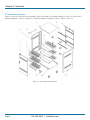
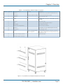
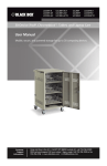
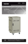
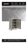
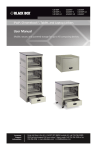
Table 2-1. Cart components labeled in Figures 2-1 and 2-2.
Number in Figure 2-1
Component Name
Quantity
Description
1
Front door
1
Locking front door, keyed differently than back door
2
Slot dividers
36 total, 12 each for 3 shelves
Protect and hold user devices in place
3
Side panel
2
One on each side of cart
4
Handle
1
Push/pull handle on left side of cart doubles as a power
cord wrap
5
Top panel
1
One on top of cart
6
Shelf
3
12 slots on each fixed shelf for devices
7
PDU brackets
6
Secure PDUs to cart frame
8
Fixed shelf mounting brackets
3
Secure shelves to cart frame
9
Back door
1
Locking back door, keyed differently than front door
10
Bottom panel
1
One on bottom of cart
11
Casters
4 total, 2 locking/swiveling,
2 non-locking/fixed
Locking/swiveling casters are on left side of cart (the
side with the handle) and non-locking fixed casters are
on right side of cart
12
Front cable manager (optional)
3
Neatly holds cables
13
Shelf depth adjuster (optional)
4
12
13
Figure 2-2. Assembled cart and optional components illustrated.
724-746-5500 | blackbox.com
Page 9