1
Serial Bus Configuration Tool
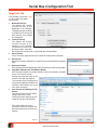
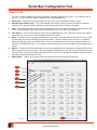
Window Tab – Shows the currently selected Tab. Other Tabs may be selected by clicking on them.
1. Selected Communications Protocol (Drop down Menu) – This displays the currently selected communications
protocol (None, DeviceNet TM, Modbus ASCII, Modbus RTU). Currently, Modbus RTU is selected (Modbus ASCII shares
the same configuration). Power to the controller must be cycled if the Communications Protocol is changed before the
change will take effect.
2. Communications Protocol Apply Button – Clicking this button applies the currently selected protocol (in this case
it would apply Modbus RTU).
3. Communications Timeout (and Apply Button) – This text box is where the communications timeout is entered. The
time value (in seconds) is used to determine if communications is lost. If communications are lost for this amount of
time, the I/O is set to the default state. Clicking the Apply button will apply the current entered value to the controller.
4. Output Base Address (Modbus) – Base address of the output holding registers.
5. Input Base Address (Modbus) – Base address of the input holding registers.
6. Module Status Base Address (Modbus) – Base address of the module status holding registers.
7. Modbus Settings Apply Button (Modbus) – This button will apply the currently displayed Modbus settings to the
controller.
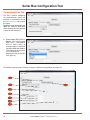
8. Serial Port Configuration Button (Modbus RTU or ASCII only) – Clicking the Serial Port Configuration button will
open the Serial Configuration Window (new window) to configure the serial port settings. Reference image below (see
figure 15).
a
b
c
d
e
f
Figure 15
a. Baud Rate – This is where the serial baud rate is selected using the drop down menu. The range is 9600 to 115200
bps. The default baud rate is 57600.
b. Parity – This is where the serial packet parity is selected using the drop down menu. The choices are NONE, ODD
and EVEN. NONE is the default parity.
c. Data Bits – This is where the number of data bits is selected using the drop down menu. The choices are 5-8. The
default number of data bits is 8.
d. Stop Bits – This is where the number of stop bits is selected using the drop down menu. The choices are 1 or 2.
The default number of stop bits is 1.
e. Communications Mode – This is where the type of serial communications is selected using the drop down menu.
The choices are RS-232 or RS-485. The default mode is RS-232.
f. Save Button – The Save button saves the current serial port settings, closes the Serial Configuration Window and
returns focus back to the Communications Tab. Power to the controller must be cycled if the Serial Port Configuration
Settings are changed before the changes will take effect.
www.rosscontrols.com
11