1
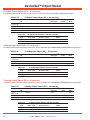
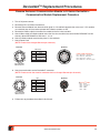
D-Series Serial Bus System DeviceNet TM ROSS CONTROLS® and MODBUS TCP ROSS CONTROLS® • User Manual 602 • ROSS CONTROLS® Table of Contents Important User Information.......................................................................... 3 Configuration Start-up Assembly of Hardware Components .............................................................. 4 Connecting the Power and Communication Cables ....................................... 5 Downloading the Software .............................................................................. 6 Configuring the Module.................................................................................... 6 Connect to Serial Bus Valve Controller............................................................ 6 Serial Bus Configuration Tool Target Info Tab................................................................................................. 7 Target I/O Tab.................................................................................................. 9 Communications Tab..................................................................................... 10 I/O Bus Tab.................................................................................................... 14 Communication Module Pinouts MODBUS TCP Communication Module ....................................................... 15 DeviceNet TM Communication Module............................................................ 15 Expansion Module, 8 Digital Inputs/8 Digital Outputs.................................... 16 Expansion Module, 8 Digital Inputs .............................................................. 16 Expansion Module, 8 Digital Outputs . .......................................................... 17 Expansion Module, 16 Digital Inputs ............................................................ 17 Expansion Module, 4 Relay Outputs ............................................................ 18 Expansion Module, 24 Digital OUT................................................................ 18 Computer to D-Series Network Connection................................................... 19 DeviceNet TM Object Model DeviceNet TM Switches................................................................................... 20 DeviceNet TM Object Model............................................................................. 20 Identity Object (01HEX - 1 Instance)................................................................. 21 Message Router Object (02HEX - 1 Instance).................................................. 21 DeviceNet TM Object (03HEX - 1 Instance)......................................................... 21 Assembly Object (04HEX - 2 Instances)............................................................ 22 Connection Object (05HEX - 3 Instances).................................................... 23-24 Acknowledge Handler Object (2BHEX - 1 instance).......................................... 25 Dynamic Input Assembly Point Object (64HEX - 1 instance)............................. 25 Dynamic Output Assembly Point Object (65HEX - 1 instance).......................... 25 24 SV Output Object (66HEX - 1 Instance)....................................................... 26 8 Digital Input Object (66HEX - 8 instances)...................................................... 26 16 Digital Input Object (67HEX - 8 instances).................................................... 26 8 Digital Output Object (68HEX - 8 instances)................................................... 27 8 Digital Input / 8 Output Object (69HEX - 8 instances)..................................... 27 4 Relay Output Object (6BHEX - 8 instances)................................................... 27 24 Digital Output Object (6CHEX - 8 Instances................................................. 28 2 Analog Input Object (6CHEX - 8 instances).................................................... 28 2 Analog Output Object (6DHEX - 8 instances)................................................. 28 DeviceNet TM Replacement Procedures........................................................ 29 Firmware Update Procedure.......................................................................... 30 Communication Module Led Status Chart..................................................... 30 Communication Module Led Status Chart..................................................... 31 Cautions....................................................................................................... 32 Warranty....................................................................................................... 33 Global Locations.......................................................................................... 33 DeviceNet TM is a trademark used under license by ODVA. 2 © 2010, ROSS CONTROLS®. All Rights Reserved. Important User Information Important User Information ATTENTION Solid state equipment has operational characteristics differing from those of electromechanical equipment. Safety Guidelines for the Application, Installation and Maintenance of Solid State Controls (Form #A10325) (available online at www.rosscontrols. com), describes some important differences between solid state equipment and hard-wired electromechanical devices. Because of these differences, and also because of the wide variety of uses for solid state equipment, all persons responsible for applying this equipment must satisfy themselves that each intended application of this equipment is acceptable. In no event will ROSS CONTROLS® be responsible or liable for indirect or consequential damages to persons or property resulting from the use or application of this equipment. The examples and diagrams in this manual are included solely for illustrative purposes. Because of the many variables and requirements associated with any particular installation, ROSS CONTROLS® cannot assume responsibility or liability for actual use based on the examples and diagrams. No patent liability is assumed by ROSS CONTROLS® with respect to use of information, circuits, equipment, or software described in this manual. Reproduction of the contents of this manual, in whole or in part, without written permission of ROSS CONTROLS® is prohibited. Throughout this manual we use notes to make you aware of safety considerations. ! Environment and Enclosure This equipment is intended for use in overvoltage Category II applications (as defined in IEC publication 60664-1), at altitudes up to 2000 meters without derating. This equipment is considered Group 1, Class A industrial equipment according to IEC/CISPR Publication 11. Without appropriate precautions, there may be potential difficulties ensuring electromagnetic compatibility in other environments due to conducted as well as radiated disturbance. This equipment is supplied as “enclosed” equipment. It should not require additional system enclosure when used in locations consistent with the enclosure type ratings stated in the Specifications section of this publication. Subsequent sections of this publication may contain additional information regarding specific enclosure type ratings, beyond what this product provides, that are required to comply with certain product safety certifications. NOTE: See NEMA Standards publication 250 and IEC publication 60529, as applicable, for explanations of the degrees of protection provided by different types of enclosures. Also, see the appropriate sections in this publication, as well as the publication A10324 (“Industrial Automation Wiring and Grounding Guidelines”), for additional installation requirements pertaining to this equipment. ATTENTION ! Preventing Electrostatic Discharge This equipment is sensitive to electrostatic discharge, which can cause internal damage and affect normal operation. Follow these guidelines when you handle this equipment: • Touch a grounded object to discharge potential static. • Wear an approved grounding wrist strap. • Do not touch connectors or pins on component boards. • Do not touch circuit components inside the equipment. • If available, use a static-safe workstation. • When not in use, store the equipment in appropriate static safe packaging. www.rosscontrols.com 3 Configuration Start-up Assembly of Hardware Components Before completing the assembly of hardware components (valves, manifolds, I/O modules, etc.), make sure the following tasks have been completed. a. Set switch addresses for all I/O modules. If using only one piece of a given module part number, the factory default setting can be used. If using more then one module with the same part number, each module needs to be addressed differently. Factory default is AAA. See I/O reference page for complete address chart. Modbus TCP Module Addressing: 1. Before assembling the D-Series modules, locate the addressing dip switches. 2. Create a list of the modules you wish to use. Group them by the type of module. Place them in order as listed below. (This is not required but it makes organizing your modules and addresses easier). All DIN 8 Modules All DIN 16 Modules All DOUT 8 Modules All DIO 8 Modules All Relay 4 Modules All DOUT 24 Modules All AIN 2 Modules All AOUT 2 Modules 3. The modules have been set at the factory with the 3 dip switches in the “A” position. If there is no other I/O modules of this type the dip switches may not need setting, however if there is another module of similar type it will be necessary to modify the address switches. There is a chart on the right with an example of the dip switch settings and their address. b. Set switch addresses for all communication modules. If using serial communications, the switches configure the address. For TCP configuration, if a static IP address is set in the software that has the last octet set to “0”, then the switches configure the last octet of the IP address. Factory default is address 0, all switches off. See Modbus Address reference page for complete address chart. c. Insert SD Card in Communication Module. If blank, all configuration programming will automatically write to the SD card. Once the configuration is complete, an option to save the configuration to the module memory is available. If the SD Card is already configured, the save to memory option can be used or the module can be run directly from the SD Card. 12C Address Selection SWHexidecimal Address # E0 E2 E4 E6 E8 EA EC EE SW1 A B A B A B A B SW2 SW3 A A A A B A B A A B A B B B B B When connecting the ribbon cable to the valve manifold, connect the 2x10 connector first and the 1x10 connector second. Make sure the arrows on the side of each connector point in the same direction, arrows up. ISO 1 Ribbon Cable RPS4024P 4 ISO 2 & 3 Ribbon Cable RPS4024P © 2010, ROSS CONTROLS®. All Rights Reserved. ISO 0 & 00 Ribbon Cable RPS5624P Configuration Start-up Connecting the Power and Communication Cables Connect to the 4 pin Power Connector. See pinout in figure 1. Connect to the Communication Connector. On the DeviceNet ™ module, use either the male or female DeviceNet ™ port. On the Modbus TCP module, use the Ethernet port. Alternatively the RS-232/RS-485 port can be selected if using serial communication. See figures 2a & 2b. ETHERNET POWER POWER 1 2 4 3 WATCHDOG WATCHDOG COMMUNICATIONS COMMUNICATIONS I/O STATUS I/O STATUS POWER CONNECTOR PINOUT PIN 1 - Black wire - +24 volts I/O IN PIN 2 - Blue wire - PE PIN 3 - Brown wire - Common PIN 4 - White wire - +24 volts Logic IN DeviceNetTM STATUS PROG / CONFIG Figure 1 RS-232 RS-485 DeviceNet PROG / CONFIG TM Figure 2a RRSSCDM12A RS-232 RS-485 Figure 2b RRSSCENXXA Model: RRSSCDM12A Address and Baude Rate Configuration Note: As shown, the MacID is 01 and the Baude rate is 125K. SW1 SW6 SW5 SW4 SW3 SW2 SW8 SW7 ON OFF BAUD MacID (Address) Rate www.rosscontrols.com 5 Serial Bus Configuration Tool Downloading the Software Go to www.rosscontrols.com to download the D Series Configuration Tool Program. This program is needed for both the DeviceNet ™ and Modbus TCP communication modules. If using the DeviceNet ™ module, also download the D Series EDS File. If using the Modbus TCP module, refer to the Register Mapping Appendix. Configuring the Module For DeviceNet ™ modules, connect to the Prog/Config port. For Modbus TCP modules, connect to the Prog/Config or the Ethernet port. See figures 2a & 2b. Install D Series Configuration Tool Program. Run Setup.exe. Open Program. Connect to Serial Bus Valve Controller To open the Ross Serial Bus Valve Controller Configuration Tool: 1. 2. 3. 4. 5. Click Start Click Programs Click ROSS Controls Click Serial Bus Click Config Tool The program will open (see figure 3). Figure 3 Select the Connection Port and Connect to the Controller: Using the drop down, select the desired connection Port: a. For connections using the Serial Configuration Cable (ROSS P/N: RR158H58). b. Select RS232 Communications port connected to D-Series System (see figure 4). Click the Connect button to connect to the controller. The Config Tool Master screen will open (see figure 5). Figure 4 For connections using the computer’s Ethernet port when the computer and D-Series system are connected to a common Ethernet network: Select: Eth: Local Area Connection (or appropriate network adapter). A list of all D-Series Systems present on the network will appear. Select the correct D-Series System (based on MAC, IP Address, or Host Name). Click OK button. Figure 5 6 © 2010, ROSS CONTROLS®. All Rights Reserved. Serial Bus Configuration Tool Target Info Tab If not selected, click on the Target Info tab to select this option (see figure 6). 1. Bootloader Version This displays the currently installed version of the bootloader in the controller. The bootloader acts as a BIOS and allows the Firmware and other features to be loaded and configured. 2. Firmware Version This displays the currently installed version of the Firmware in the controller. The firmware is similar to an operating system. It provides the functionality that operates in conjunction with the bootloader. Figure 6 3. Serial Number This is the factory programmed serial number of the Serial Bus Controller. 4. Window Tab Shows the currently selected Tab. Other Tabs may be selected by clicking on them. 5. Disconnect Button Click will disconnect the Configuration Tool from the actual Serial Bus Controller. 6. Copy SD Card Setting To Unit Memory Button Click will copy D-Series unit settings stored on SD Card installed in D-Series unit to unit’s internal memory. Clicking this button will bring up the screen on the right (see figure 7). This indicates that unit settings were successfully copied from the SD Card installed in the D-Series unit to the unit’s internal memory. 7. Figure 7 Save Current Unit Settings To File Button Click will save the current D-Series configuration data to a file. Clicking this button will bring up the screen on the right (see figure 8). This screen allows the user to choose the location to save the .dat file which contains the D-Series unit settings. Figure 8 www.rosscontrols.com 7 Serial Bus Configuration Tool 8. Load Unit Settings From File Button Click to load D-Series configuration from a data file. Note: If a SD Card is installed in the D-Series unit, the settings will be stored only in the SD Card unless the user clicks the “Copy SD Card Settings to Unit Memory” button to manually copy the unit setting from the SD card to the unit’s internal memory. Clicking this button will bring up the screen on the right (see figure 9). Figure 9 Click YES to confirm that new settings are to be written to the D-Series unit. A file-open screen will then be displayed (see figure 10). Figure 10 Select the .dat file containing the unit settings to be loaded into the D-Series unit. The setting in this file will then be loaded into the D-Series unit. Note: If a SD Card is installed in the D-Series unit, the settings will be stored only in the SD Card unless the user clicks the “Copy SD Card Settings to Unit Memory” button to manually copy the unit setting from the SD card to the unit’s internal memory. NOTE: If a unit settings .dat file loaded on an SD card installed in the D-Series unit is determined to be invalid, the red I/O Status LED will flash at 5 Hz. The unit will not operate until a valid configuration is loaded to the SD card (or the SD card is removed). 8 © 2010, ROSS CONTROLS®. All Rights Reserved. Serial Bus Configuration Tool Target I/O Tab This tab is used for controlling and viewing controller I/O (directly controlled, not via bus). If not selected, click on the Target I/O tab to select this option. Reference next image (see figure 11). 1. Window Tab – Shows the currently selected Tab. Other Tabs may be selected by clicking on them. 2. Solenoid Valve Number (1-24) – This is the solenoid valve number. There can be up to 24 directly controlled solenoid valves. Use this header to identify the solenoid valve that is to be viewed or controlled. 3. State – The State check box is used to control the solenoid valve (1-24). When checked, the solenoid valve is ON or turns ON immediately. When unchecked, the solenoid valve is OFF or turns OFF immediately. 4. Valve Status – This status box displays current status of Solenoid Valve (1-24). The status can be Open, Normal, or Shorted. The valve status is only valid when the valve state is OFF. 5. Active – Solenoid valve active check box determines if the valve status information (for the specific valve) is used in internal logic to set the I/O STATUS LED on the controller. If Active is checked, the valve status is included in determining the status of the I/O STATUS LED. If Active is not checked, the valve status is ignored and does not affect the I/O STATUS LED status. Any changes to the Active check box will not take effect until the Apply button is clicked. 6. Default – The default check box determines the state of the Solenoid Valve in the event all Communications is lost. When checked, if all communications is lost, the solenoid valve will be ON or turn ON. If not checked, the loss of all communications will cause the solenoid valve to be OFF or turn OFF. Any changes to the Default check box will not take effect until the Apply button is clicked. 7. Apply Button – Causes any changes made to the Default or Active check boxes to take effect. 1 2 3 4 5 6 7 Figure 11 www.rosscontrols.com 9 Serial Bus Configuration Tool Communications Tab This tab is used for configuring the communications ports and protocols. If not selected, click on the Communications tab to select this option. Reference image on the right (see figure 12). Using the drop down menu, the communications protocol is selected and configured. Figure 12 A. Select Modbus RTU, ASCII or Modbus TCP using the drop down menu. The Modbus RTU or ASCII refers to communications via the Serial Port (RS-232/RS-485). Modbus TCP refers to communications via the Ethernet port. Reference image on the right (see figure 13). Figure 13 The Modbus communications settings will appear. Reference image below (see figure 14). 1 2 8 3 4 5 6 7 Figure 14 10 © 2010, ROSS CONTROLS®. All Rights Reserved. Serial Bus Configuration Tool Window Tab – Shows the currently selected Tab. Other Tabs may be selected by clicking on them. 1. Selected Communications Protocol (Drop down Menu) – This displays the currently selected communications protocol (None, DeviceNet TM, Modbus ASCII, Modbus RTU). Currently, Modbus RTU is selected (Modbus ASCII shares the same configuration). Power to the controller must be cycled if the Communications Protocol is changed before the change will take effect. 2. Communications Protocol Apply Button – Clicking this button applies the currently selected protocol (in this case it would apply Modbus RTU). 3. Communications Timeout (and Apply Button) – This text box is where the communications timeout is entered. The time value (in seconds) is used to determine if communications is lost. If communications are lost for this amount of time, the I/O is set to the default state. Clicking the Apply button will apply the current entered value to the controller. 4. Output Base Address (Modbus) – Base address of the output holding registers. 5. Input Base Address (Modbus) – Base address of the input holding registers. 6. Module Status Base Address (Modbus) – Base address of the module status holding registers. 7. Modbus Settings Apply Button (Modbus) – This button will apply the currently displayed Modbus settings to the controller. 8. Serial Port Configuration Button (Modbus RTU or ASCII only) – Clicking the Serial Port Configuration button will open the Serial Configuration Window (new window) to configure the serial port settings. Reference image below (see figure 15). a b c d e f Figure 15 a. Baud Rate – This is where the serial baud rate is selected using the drop down menu. The range is 9600 to 115200 bps. The default baud rate is 57600. b. Parity – This is where the serial packet parity is selected using the drop down menu. The choices are NONE, ODD and EVEN. NONE is the default parity. c. Data Bits – This is where the number of data bits is selected using the drop down menu. The choices are 5-8. The default number of data bits is 8. d. Stop Bits – This is where the number of stop bits is selected using the drop down menu. The choices are 1 or 2. The default number of stop bits is 1. e. Communications Mode – This is where the type of serial communications is selected using the drop down menu. The choices are RS-232 or RS-485. The default mode is RS-232. f. Save Button – The Save button saves the current serial port settings, closes the Serial Configuration Window and returns focus back to the Communications Tab. Power to the controller must be cycled if the Serial Port Configuration Settings are changed before the changes will take effect. www.rosscontrols.com 11 Serial Bus Configuration Tool 9. Ethernet Options Button (Modbus TCP only) Clicking the Ethernet Options Configuration button will open the Ethernet Options Window (new window) to configure the serial port settings. Reference image below (see figure 16). a b c d e f Figure 16 a. MAC – The Ethernet MAC Address of the unit. This is the physical address of the unit set at the factory, this cannot be changed. b. Ethernet Enabled – Enables (checked) or disables (unchecked) the Ethernet Interface. c. DHCP Enabled – When checked the unit will acquire an IP Address from a DHCP server on the network d. IP v4 Auto Config – When checked the unit will automatically configure its IP Address using 169.254/16 prefix see, http://www.faqs.org/rfcs/rfc3927.html. Use this option when neither DHCP nor Static IP can be used. This will ensure that all units have a unique IP Address. Units that Auto Configure will have an IP address in the following range: [169.254.1.0 to 169.254.254.255]. e. Static IP Options – When both DHCP and IP v4 Auto Config are disabled the user may enter the IP configuration manually. Talk to your network administrator in order to determine what values to use. Note: If a static IP address is used and set to X.X.X.0, the DIP switches on the unit will set the last octet of the IP address (X represents the numerical IP Address Valves 0-255). f. Host Name – The name used on the network by the unit. The factory default will be SB_ (Serial Bus) followed by the last three octets of the MAC address. This name should be unique. 12 © 2010, ROSS CONTROLS®. All Rights Reserved. Serial Bus Configuration Tool B. Select DeviceNet TM using the drop down menu. DeviceNet TM refers to communications via the DeviceNet TM Port Reference image below (see figure 17). 1 2 3 4 8 9 5 11 6 7 10 Figure 17 1. Window Tab – Shows the currently selected Tab. Other Tabs may be selected by clicking on them. 2. Selected Communications Protocol (Drop down Menu) – This displays the currently selected communications protocol (None, DeviceNet TM, Modbus ASCII, Modbus RTU). Currently, DeviceNet TM is selected. Power to the controller must be cycled if the Communications Protocol is changed before the change will take effect. 3. Communications Protocol Apply Button – Clicking this button applies the currently selected protocol (in this case it would apply DeviceNet TM). 4. Communications Timeout (and Apply Button) – This text box is where the communications timeout is entered. The time value (in seconds) is used to determine if communications is lost. If communications are lost for this amount of time, the I/O is set to the default state. Clicking the Apply button will apply the current entered value to the controller. 5. TMMAC ID – DeviceNet TM MAC ID. This is a read only. This displays the controllers hardware set address (set by internal DIP switches). 6. Baud Rate – DeviceNet TM baud rate. This rate is set by internal DIP switches. 7. Input Size – Size in bytes of I/O Messaging Input block. This is Assembly Object Class 0, Attribute ID 101. See DeviceNet TM Object Model for details. 8. DeviceNet TM Power Present – This box will be checked when power is detected on the DeviceNet TM bus (power pin). 9. Static Module Configuration – This checkbox identifies the status of the module: Static or Dynamic. 10.Output Size – Size in bytes of I/O Messaging Output block. This is Assembly Object Class 0, Attribute ID 103. See DeviceNet TM Object Model for details. 11.Set/Clr Static Module Configuration Button – This button will toggle the Static Configuration. When set, it will query, identify and store the connected module settings. When clear, the settings are reset (and the Static Module Configuration Checkbox). Note: If the Baud rate switches are both ON during power up, then this will reset the configuration to dynamic. www.rosscontrols.com 13 Serial Bus Configuration Tool I/O Bus Tab This tab is used for viewing and controlling the Serial Bus I/O. If not selected, click on the I/O Bus tab to select this option. Reference image below (see figure 18). 1 2 3 4 a b c d Figure 18 1. Window Tab – Shows the currently selected Tab. Other Tabs may be selected by clicking on them. 2. I/O Bus Window – This window displays the currently connected I/O device modules connected to the serial bus controller (address and description). 3. Apply Default State Button – Clicking this button applies the default states for the connected I/O modules (selected or not selected). 4. I/O Device Module Control Panel – This box provides the viewing and controlling interface for the connected I/O Modules. Each module will have its own individual outlined control box with the address, short description and number of I/O points. Changing the checkboxes will change the corresponding I/O points accordingly. a. Out Checkbox – This checkbox when clicked active will force the corresponding output point to energize or be ON. b. Default State – The default checkbox determines the state of the output in the event all communications is lost. When checked, if all communications is lost, the output will be ON or turn ON. If not checked, the loss of all communications will cause the output to be OFF or turn OFF. Any changes to the Default checkbox will not take effect until the Apply Default State button is clicked. c. In Box – The IN box will be checked or true when the actual corresponding digital input point is true or energized. d. Stat – The stat checkbox will be true if the Output point is operational and considered ‘Normal’. If false, then the output is in one of several modes: Current Limitation, Overtemperature, Undervoltage, Overvoltage, etc. 14 © 2010, ROSS CONTROLS®. All Rights Reserved. Communication Module Pinouts Model Number RRSSCENXXA – MODBUS TCP Communication Module 1 4 3 2 POWER CONNECTOR PINOUT PIN 1 - Black wire - +24 Volts I/O IN PIN 2 - Blue wire - PE Ground PIN 3 - Brown wire - Common PIN 4 - White wire - +24 Volts Logic IN B 1 2 1 2 5 4 3 1 2 5 4 3 4 3 PROG/CONFIG RS-232 RS-485 ETHERNET D-Code PRGM/CONFIG PINOUT PIN 1 - (NO Connection) PIN 2 - RXD IN PIN 3 - TXD OUT PIN 4 - (NO Connection) PIN 5 - Common B RS-232 RS-485 PINOUT PIN 1 - RS485A PIN 2 - RXD IN PIN 3 - TXD OUT PIN 4 - RS485B PIN 5 - Common B ETHERNET PINOUT PIN 1 - TX + OUT PIN 2 - RX + IN PIN 3 - TX - OUT PIN 4 - RX - IN Notes: For serial communications, the switches configure the address. For TCP configuration, if a static IP address is set in the software that has the last octet set to “0”, the switches configure the last octet of the IP address. MODBUS Address ecimalBinary Address D Address SW1 SW2 SW3 SW4 SW5 SW6 SW7 0 OFF OFF OFF OFF OFF OFF OFF SW8 OFF OFF OFF 1 ON OFF OFF OFF OFF OFF OFF 2 OFF ON OFF OFF OFF OFF OFF 254 OFF ON ON ON ON ON ON 255 ON ON ON ON ON ON ON ON ON Model Number RRSSCDM12A – DeviceNet TM Communication Module 1 2 4 1 2 5 4 3 1 2 5 4 3 PROG/CONFIG RS-232 RS-485 1 1 2 2 5 3 4 4 3 1 2 5 4 3 3 POWER CONNECTOR PINOUT PIN 1 - Black wire - +24 Volts I/O IN PIN 2 - Blue wire - PE Ground PIN 3 - Brown wire - Common PIN 4 - White wire - +24 Volts Logic IN B PRGM/CONFIG PINOUT PIN 1 - (NO Connection) PIN 2 - RXD IN PIN 3 - TXD OUT PIN 4 - (NO Connection) PIN 5 - Common B RS-232 RS-485 PINOUT PIN 1 - RS485A PIN 2 - RXD IN PIN 3 - TXD OUT PIN 4 - RS485B PIN 5 - Common DeviceNetTM DeviceNetTM B DeviceNetTM PINOUT PIN 1 - Shield PIN 2 - +Volts Sense PIN 3 - Common PIN 4 - CAN H PIN 5 - CAN L B DeviceNetTM PINOUT PIN 1 - Shield PIN 2 - +Volts Sense PIN 3 - Common PIN 4 - CAN H PIN 5 - CAN L Notes: For addressing information refer to DeviceNetTM object model section at the end of the Manual. Electrical Specifications: For product on this page. Valve Outputs, 24 Total: Solid State: Current sourcing; 10-28 Volts DC @ 0.5A Max.; Short circuit protection; Fault Detection. PROG/CONFIG: Used for configuration and setup. RS-232/RS-485: MODBUS ASCII/RTU port. RS485, RS232 – software selectable. Baud Rate Selectable. Ethernet port: For model RRSSCENXXA. Used for MODBUS TCP D-Code. The device address is set by an 8 position DIP Switch Sets device address as follows: For MODBUS TCP set last 8 bits of IP address: ex: 168.192.1.XXX, IP address to be static (user configurable). For other buses, sets address. DeviceNetTM Port: For model RRSSCDM12A. Used for DeviceNetTM communications. I/O Expansion Port: Allows connection to Plug-in I/O modules: Max 256 Digital I/O points; Max 16 Analog I/O points; I2C Interface. Power Requirements: 24 Volts DC for the I/O, Current Demand is Output Load dependent, 24 Volts DC for the Logic, 50mA Max. IMPORTANT NOTE: Please read carefully and thoroughly all of the CAUTIONS on the inside back cover. www.rosscontrols.com 15 Input/Output Module Pinouts Model Number RRSSN88M12A – Expansion Module, 8 Digital Inputs/8 Digital Outputs J1 PINOUT PIN 1 - +24 Volts PIN 2 - Input #2 PIN 3 - Common PIN 4 - Input #1 PIN 5 - (NO Connection) J5 PINOUT PIN 1 - +24 Volts PIN 2 - Output #2 PIN 3 - Common PIN 4 - Output #1 PIN 5 - (NO Connection) J2 PINOUT PIN 1 - +24 Volts PIN 2 - Input #4 PIN 3 - Common PIN 4 - Input #3 PIN 5 - (NO Connection) J6 PINOUT PIN 1 - +24 Volts PIN 2 - Output #4 PIN 3 - Common PIN 4 - Output #3 PIN 5 - (NO Connection) J3 PINOUT PIN 1 - +24 Volts PIN 2 - Input #6 PIN 3 - Common PIN 4 - Input #5 PIN 5 - (NO Connection) J7 PINOUT PIN 1 - +24 Volts PIN 2 - Output #6 PIN 3 - Common PIN 4 - Output #5 PIN 5 - (NO Connection) J4 PINOUT PIN 1 - +24 Volts PIN 2 - Input #8 PIN 3 - Common PIN 4 - Input #7 PIN 5 - (NO Connection) J8 PINOUT PIN 1 - +24 Volts PIN 2 - Output #8 PIN 3 - Common PIN 4 - Output #7 PIN 5 - (NO Connection) IN 7 OUT 7 IN 1 OUT 1 IN 2 OUT 2 J1 2 3 5 1 4 4 1 5 3 2 J4 J5 IN 8 OUT 8 IN 3 OUT 3 IN 4 OUT 4 J2 J8 J6 IN 5 OUT 5 IN 6 OUT 6 J3 J7 IN 7 OUT 7 IN 8 OUT 8 J4 SW# SW1A SW2A SW3A SW4A J8 Input Mode Selection Input# Sinking Sourcing Input 1/2 Input 3/4 Input 5/6 Input 7/8 A A A A B B B B 12C Address Selection SWHexidecimal Address B0 B2 B4 B6 B8 BA BC BE # SW1 A B A B A B A B SW2 SW3 A A A A B A B A A B A B B B B B Model Number RRSSN8XM12A – Expansion Module, 8 Digital Inputs J1 PINOUT PIN 1 - +24 Volts PIN 2 - Input #2 PIN 3 - Common PIN 4 - Input #1 PIN 5 - (NO Connection) J3 PINOUT PIN 1 - +24 Volts PIN 2 - Input #6 PIN 3 - Common PIN 4 - Input #5 PIN 5 - (NO Connection) J2 PINOUT PIN 1 - +24 Volts PIN 2 - Input #4 PIN 3 - Common PIN 4 - Input #3 PIN 5 - (NO Connection) IN 7 IN 1 J4 PINOUT PIN 1 - +24 Volts PIN 2 - Input #8 PIN 3 - Common PIN 4 - Input #7 PIN 5 - (NO Connection) J1 IN 2 4 1 5 3 2 J4 IN 8 IN 3 J2 IN 4 IN 5 12C Address Selection SWHexidecimal Address # 40 42 44 46 48 4A 4C 4E SW1 A B A B A B A B SW2 SW3 A A A A B A B A A B A B B B J3 IN 6 IN 7 J4 B B Electrical Specifications: For product on this page. Inputs: Input Voltage Range:10-28 Volts DC. Input Current: 9mA Nominal @ 24 Volts DC. Input Resistance: 5.1KΩ Nominal. “Sinking” or “Sourcing” Mode, switch selectable in pairs. LED indicators, LED Load Current 5mA nominal @ 24Volts DC. Logic Power Requirements: 3.3V@10mA Max from the Controller. IN 8 SW# SW1A SW2A SW3A SW4A Input Mode Selection Input# Sinking Sourcing Input 1/2 Input 3/4 Input 5/6 Input 7/8 A A A A Outputs: Solid-State, Sourcing. 10-28 Volts DC @ 3A Max. Short circuit protection. Fault Detection. LED indicators, LED Load Current 5mA nominal @ 24 Volts DC. Logic Power Requirements: 3.3V@10mA Max from the Controller. IMPORTANT NOTE: Please read carefully and thoroughly all of the CAUTIONS on the inside back cover. 16 B B B B © 2010, ROSS CONTROLS®. All Rights Reserved. Input/Output Module Pinouts Model Number RRSST8XM12A – Expansion Module, 8 Digital Outputs J1 PINOUT PIN 1 - +24 Volts PIN 2 - Input #2 PIN 3 - Common PIN 4 - Input #1 PIN 5 - (NO Connection) J3 PINOUT PIN 1 - +24 Volts PIN 2 - Input #6 PIN 3 - Common PIN 4 - Input #5 PIN 5 - (NO Connection) J2 PINOUT PIN 1 - +24 Volts PIN 2 - Input #4 PIN 3 - Common PIN 4 - Input #3 PIN 5 - (NO Connection) J4 PINOUT PIN 1 - +24 Volts PIN 2 - Input #8 PIN 3 - Common PIN 4 - Input #7 PIN 5 - (NO Connection) IN 7 OUT 1 OUT 2 J1 2 3 5 1 4 J4 2 3 5 1 4 J8 IN 8 OUT 3 OUT 4 J2 OUT 5 OUT 6 12C Address Selection SWHexidecimal Address # A0 A2 A4 A6 A8 AA AC AE SW1 A B A B A B A B SW2 SW3 A A A A B A B A A B A B B B J3 OUT 7 OUT 8 J4 B B Model Number RRSSN16M12A – Expansion Module, 16 Digital Inputs J1 PINOUT PIN 1 - +24 Volts PIN 2 - Input #2 PIN 3 - Common PIN 4 - Input #1 PIN 5 - (NO Connection) J5 PINOUT PIN 1 - +24 Volts PIN 2 - Output #10 PIN 3 - Common PIN 4 - Output #9 PIN 5 - (NO Connection) J2 PINOUT PIN 1 - +24 Volts PIN 2 - Input #4 PIN 3 - Common PIN 4 - Input #3 PIN 5 - (NO Connection) J6 PINOUT PIN 1 - +24 Volts PIN 2 - Output #12 PIN 3 - Common PIN 4 - Output #11 PIN 5 - (NO Connection) J3 PINOUT PIN 1 - +24 Volts PIN 2 - Input #6 PIN 3 - Common PIN 4 - Input #5 PIN 5 - (NO Connection) J7 PINOUT PIN 1 - +24 Volts PIN 2 - Output #14 PIN 3 - Common PIN 4 - Output #13 PIN 5 - (NO Connection) J4 PINOUT PIN 1 - +24 Volts PIN 2 - Input #8 PIN 3 - Common PIN 4 - Input #7 PIN 5 - (NO Connection) J8 PINOUT PIN 1 - +24 Volts PIN 2 - Output #16 PIN 3 - Common PIN 4 - Output #15 PIN 5 - (NO Connection) IN 1 J1 IN 9 IN 7 IN 2 IN 10 IN 3 IN 11 IN 8 J2 IN 4 IN 12 J6 J3 IN 6 IN 14 J7 IN 7 IN 15 J4 IN 8 IN 16 J8 12C Address Selection SWHexidecimal Address # 50 52 54 56 58 5A 5C 5E SW1 A B A B A B A B A A A A IN 16 IN 5 IN 13 SW2 SW3 4 1 5 3 2 J4 J5 IN 15 B A B A A B Electrical Specifications: For product on this page. Inputs: Input Voltage Range:10-28 Volts DC. Input Current: 9mA Nominal @ 24 Volts DC. Input Resistance: 5.1KΩ Nominal. “Sinking” or “Sourcing” Mode, switch selectable in pairs. LED indicators, LED Load Current 5mA nominal @ 24Volts DC. Logic Power Requirements: 3.3V@10mA Max from the Controller. A B B B B B SW# Input Mode Selection Input# Sinking Sourcing SW1A SW2A SW3A SW4A SW5A SW6A SW7A SW8A Input 1/2 Input 3/4 Input 5/6 Input 7/8 Input 9/10 Input 11/12 Input 13/14 Input 15/16 A A A A A A A A B B B B B B B B Outputs: Solid-State, Sourcing. 10-28 Volts DC@3A Max. Short circuit protection. Fault Detection. LED indicators, LED Load Current 5mA nominal @ 24 Volts DC. Logic Power Requirements: 3.3V@10mA Max from the Controller. IMPORTANT NOTE: Please read carefully and thoroughly all of the CAUTIONS on the inside back cover. www.rosscontrols.com 17 Input/Output Module Pinouts Model Number RRSSTR4M12A – Expansion Module, 4 Relay Outputs OUTPUT 1 PINOUT PIN 1 - +24 Volts PIN 2 - Contact Common PIN 3 - 24 Volts Common PIN 4 - N.O. Contact PIN 5 - N.C. Contact OUTPUT 3 PINOUT PIN 1 - +24 Volts PIN 2 - Contact Common PIN 3 - 24 Volts Common PIN 4 - N.O. Contact PIN 5 - N.C. Contact OUTPUT 2 PINOUT PIN 1 - +24 Volts PIN 2 - Contact Common PIN 3 - 24 Volts Common PIN 4 - N.O. Contact PIN 5 - N.C. Contact OUTPUT 4 PINOUT PIN 1 - +24 Volts PIN 2 - Contact Common PIN 3 - 24 Volts Common PIN 4 - N.O. Contact PIN 5 - N.C. Contact OUT 1 4 1 5 3 2 2 3 5 1 4 OUTPUT 1 OUTPUT 2 4 1 5 3 2 2 3 5 1 4 12C Address Selection SWHexidecimal Address # E0 E2 E4 E6 E8 EA EC EE SW1 A B A B A B A B SW2 SW3 A A A A B A B A A B A B B B OUT 2 OUT 3 OUTPUT 3 OUT 4 OUTPUT 4 B B Electrical Specifications: Relay Outputs: Form C (SPDT) 115Volts AC @3A Max. 24 Volts DC @4A 24 Volts Power Requirements: 33mA per activated relay. Logic Power Requirements: 3.3 Volts @15mA Max from the Controller. Model Number RRSST24UBA – Expansion Module, 24 Digital OUT 12C Address Selection SWHexidecimal Address # C0 C2 C4 C6 C8 CA CC CE SW1 A B A B A B A B SW2 SW3 A A A A B A B A A B A B Electrical Specifications: Outputs: Solid-State, Sourcing. 10-28 Volts DC @ 0.5A Max. Short circuit protection. Fault Detection. Logic Power Requirements: 3.3 Volts @12mA Max from the Controller. B B 13 25 1 14 B B OUTPUTS PINOUT PIN 1 - Output Solenoid #1 PIN 2 - Output Solenoid #3 PIN 3 - Output Solenoid #5 PIN 4 - Output Solenoid #7 PIN 5 - Output Solenoid #9 PIN 6 - Output Solenoid #11 PIN 7 - Output Solenoid #13 PIN 8 - Output Solenoid #15 PIN 9 - Output Solenoid #17 PIN 10 - Output Solenoid #19 PIN 11 - Output Solenoid #21 PIN 12 - Output Solenoid #23 PIN 13 - Common PIN 14 - Output Solenoid #2 PIN 15 - Output Solenoid #4 PIN 16 - Output Solenoid #6 PIN 17 - Output Solenoid #8 PIN 18 - Output Solenoid #10 PIN 19 - Output Solenoid #12 PIN 20 - Output Solenoid #14 PIN 21 - Output Solenoid #16 PIN 22 - Output Solenoid #18 PIN 23 - Output Solenoid #20 PIN 24 - Output Solenoid #22 PIN 25 - Output Solenoid #24 IMPORTANT NOTE: Please read carefully and thoroughly all of the CAUTIONS on the inside back cover. 18 © 2010, ROSS CONTROLS®. All Rights Reserved. Computer to D-Series Network Connection RJ 45 Type “B” Crossover Cable Connection RJ 45 Type “A” Straight Cable Connection RJ 45 Plug Type “A” Ethernet Cable Wiring (Straight for connection to a network switch): RJ45 Pin # Wire Color (T568A) 1 Wire Diagram (T568A) 10Base-T Signal 100Base-TX Signal Signal M12 4 Pin D-Code Pin # White/Green Transmit+ BI_DA+ 1 2 Green Transmit- BI_DA- 3 White/Orange Receive+ BI_DB+ 3 2 4 Blue Unused BI_DC+ 5 White/Blue Unused BI_DC- 6 Orange Receive- BI_DB- 7 White/Brown Unused BI_DD+ 8 Brown Unused BI_DD- 4 Type “B” Ethernet Cable Wiring (Straight for connection to a network switch): 10Base-T Signal 100Base-TX Signal Signal M12 4 Pin D-Code Pin # White/Orange Transmit+ BI_DA+ 1 2 Orange Transmit- BI_DA- 3 3 White/Green Receive+ BI_DB+ 2 4 Blue Unused BI_DC+ 5 White/Blue Unused BI_DC- 6 Green Receive- BI_DB- 7 White/Brown Unused BI_DD+ 8 Brown Unused BI_DD- RJ45 Pin # Wire Color (T568B) 1 Wire Diagram (T568B) www.rosscontrols.com 4 19 DeviceNet TM Object Model DeviceNet TM Switches The MacID (or Address on the DeviceNet TM network) and the network baud rate can be set by using eight DIP switches, see Figure 1‑1. ON ON Figure 1‑1 OFF DeviceNet switches DIP The first six switches (1-6) to the MAC ID or DeviceNet TM address are described in Table 1‑1. Table 1-1 Switches (1-6) for MAC ID or DeviceNet TM address Address Decimal 01 15 40 63 (default) SW1 20 ON ON OFF ON SW2 21 OFF ON OFF ON SW3 22 OFF ON OFF ON SW4 23 OFF ON ON ON SW5 24 OFF OFF OFF ON SW6 25 OFF OFF ON ON The last two DIP switches (7-8) control the DeviceNet TM network baud rate. See Table 1‑2. Table 1-2Switches 7 and 8 for baud rate Baud Rate/ SW Mode 125K 250K 500K Restored default settings SW1 20 OFF ON OFF ON SW2 21 OFF OFF ON ON Note: The factory default switch settings are Address 63 and 125K. DeviceNet TM Object Model Table 2‑1 describes data types used in this Object Model. 20 Table 2-1 Data Types Description Unsigned Short Integer (8-bit) Unsigned Integer (16-bit) Unsigned Double Integer (32-bit) Signed Integer (16-bit) Character String (1 byte per character) Character String (1st byte is length; up to nn characters) Bit String (8-bits) Bit String (16-bits) Bit String (32-bits) IEEE 32-bit Single Precision Floating Point Data Type USINT UINT UDINT INT STRING SHORT STRINGnn BYTE WORD DWORD REAL © 2010, ROSS CONTROLS®. All Rights Reserved. DeviceNet TM Object Model Identity Object (01HEX - 1 Instance) The following tables contain the attribute, status, and common services information for the Identity Object. Table 2-2 Identity Object (01HEX - 1 Instance) Instance Attribute Name DeviceNet TM Data ID Data Type Value Class 1 Revision UINT 1 (Instance 0) Instance 1 1 Vendor Number UINT 31 2 Device Type UINT 0 3 Product Code Number UINT 33 Product major revision USINT 2 4 Product minor revision USINT 6 5 Status WORD Varies 6 Serial Number UDINT Unique 32 bit value 7 Product Name SHORT STRING 32 Fill in Access Rule Get Get Get Get Get Get Get Get GET Table 2-3Identity Object’s common services ServiceImplemented for Service Code Class Level Instance Level Name 05 Hex No Yes Reset 0EHex Yes Yes Get_Attribute_Single 10 Hex No Yes Get_Attribute_Single Message Router Object (02HEX - 1 Instance) (No required attributes.) DeviceNet TM Object (03HEX - 1 Instance) The following tables contain the attribute and common services information for the DeviceNet TM Object. Table 2-4 DeviceNet TM Object (01HEX - 1 Instance) Instance Attribute Name DeviceNet TM Data ID Data Type Value Class 1 Revision UINT 2 (Instance 0) MAC ID USINT 63 Instance 1 1 2 Baud Rate USINT 0 Structure of 5 Allocation Choice Byte Byte Master’s MAC ID USINT 0 6 MAC ID Switch changed BOOL 0 Baud Rate Switch changed BOOL 0 7 MAC ID Switch value USINT 0 8 Baud Rate Switch value USINT 0 9 Table 2-5 Access Rule Get Get Get Get 0xFF Get Get Get Get Get DeviceNet TM Object’s common services ServiceImplemented for Service Code Class Level Instance Level Name 0EHex Yes Yes Get_Attribute_Single 10 Hex No Yes Get_Attribute_Single www.rosscontrols.com 21 DeviceNet TM Object Model Assembly Object (04HEX - 2 Instances) The following tables contain the attribute, instance, data mapping, and common services information for the Assembly Object. Table 2-6 Assembly Object (04 HEX - 2 Instances) Instance Attribute Name DeviceNet TM Data Access ID Data Type Value Rule Class 1 Revision UINT 2 Get (Instance 0) 2 Max instance UINT 0x81 Get Instance 1 100 Input index USINT 0x64 Get/Set Input size (in bytes) UINT 0x00 Get 101 102 Output index USINT 0x70 Get/Set 103 Output size (in bytes) UINT 0x00 Get Input 3 Input Get Byte Data Field 0-3 T->O dynamic assembly point instance 1 Instance 0X64 4-7 T->O dynamic assembly point instance 2 ... 248-251 T->O dynamic assembly point instance 63 251-255 T->O dynamic assembly point instance 64 Output 3 Output Get/Set Instance 0X70 0-3 O->T dynamic assembly point instance 1 4-7 O->T dynamic assembly point instance 2 ... 248-251 O->T dynamic assembly point instance 63 251-255 O->T dynamic assembly point instance 64 *These valves are stored to NVRAM. Table 2-7 Assembly Output instance data mapping Data Component Class Name Class Number Name Instance Number Attribute Number Table 2-8 Assembly Input instance data mapping Data Component Class Name Class Number Name Instance Number Table 2-9Assembly Object’s common services ServiceImplemented for Service Code Class Level Instance Level Name 0EHex Yes Yes Get_Attribute_Single 10 Hex No Yes Get_Attribute_Single 22 © 2010, ROSS CONTROLS®. All Rights Reserved. Attribute Number DeviceNet TM Object Model Connection Object (05HEX - 3 Instances) The following tables contain the attribute, and common services information for the Connection Object. Table 2-10Connection Object (01HEX - 1 Instance) Instance Attribute Name DeviceNet TM ID Data Type Class 1 Revision UINT (Instance 0) Instance 1 1 State USINT Explicit Connection 2 Instance type USINT 3 Transport trigger USINT 4 Produced UINT Data Value 1 5 connection ID Consumed UINT connection ID 6 Initial communication character USINT 7 Produced connection size UINT 8 Consumed connection size UINT 9 Expected packet rate UINT 12 Watchdog timeout action USINT 13 Produced connection path length UINT 14 Produced connection path USINT Array 15 Consumed connection path length UINT 16 Consumed connection path USINT Array Instance 2 1 State USINT Polled I/O 2 Instance type USINT 3 Transport trigger USINT 4 Produced UINT xxxxxx=Node Address Get 10xxxxxx100 BIN xxxxxx=Node Address Get 83 HEX Fill in Get Fill in Get 2500 msec Get 4=deferred delete Get 0 Get Null Get/Set* 0 Get Null Get/Set* 0=Nonexistent Get 1=Configuring 3=Established 4=Time out 1 Get 82HEX Get 01111xxxxxx11BIN Get connection ID 5 Consumed UINT connection ID 6 Initial communication character USINT 7 Produced connection size UINT 8 Consumed connection size UINT 9 Expected packet rate UINT 12 Watchdog timeout action USINT 13 Produced connection path length UINT 14 Produced connection path USINT Array 15 Consumed connection path length UINT 16 Consumed connection path USINT Array *These values are stores to NVRAM. xxxxxx=Node Address Get 10xxxxxx100 BIN xxxxxx=Node Address Get 01HEX Fill in Get Fill in Get 0 Get/Set 0=Timeout Get/Set Fill in Get/Set* Fill in Get Fill in Get Fill in Get/Set* www.rosscontrols.com Access Rule Get 0=Nonexistent Get 3=Established 5=Deferred Delete 0 Get Get 83 HEX 10xxxxxx11BIN Get 23 DeviceNet TM Object Model Connection Object (05HEX - 3 Instances) The following tables contain the attribute, and common services information for the Connection Object. Table 2-10Connection Object (01HEX - 1 Instance) Instance Attribute Name DeviceNet TM Data Access ID Data Type Value Rule Class 1 Revision UINT 1 Get (Instance 0) Instance 4 1 State USINT 0=Nonexistent Get Change of 1=Configuring State/Cyclic 3=Established Acknowledged 4=Time Out 2 Instance Type USINT 1 Get 3 Transport Trigger USINT 02HEX =Cyclic Get 12HEX =Change of State 4 Produced UINT 01101xxxxxxBIN Get connection ID xxxxxx=Node Address 5 Consumed UINT 10xxxxxx010 BIN Get connection ID xxxxxx=Node Address 6 Initial communication character USINT 01HEX Get 7 Produced connection size UINT Fill in Get 8 Consumed connection size UINT 0 Get 9 Expected packet rate UINT 0 Get/Set 12 Watchdog timeout action USINT 0=Timeout Get 13 Produced connection path length UINT 6 Get 14 Produced connection path USINT Array Fill in Get 15 Consumed connection path length UINT 4 Get 16 Consumed connection path USINT Array 0x20 0x2B 0x24 0x01 Get Instance 4 1 State USINT 0=Nonexistent Get Change of 1=Configuring State/Cyclic 3=Established Unacknowledged 4=Time Out 2 Instance Type USINT 1 Get 3 Transport Trigger USINT 02HEX =Cyclic Get 12HEX =Change of State 4 Produced UINT 01101xxxxxxBIN Get connection ID xxxxxx=Node Address 5 Consumed connection ID UINT FFFFHEX Get 6 Initial communication character USINT 0FHEX Get 7 Produced connection size UINT Fill in Get 8 Consumed connection size UINT Fill in Get 9 Expected packet rate UINT 0 Get/Set 12 Watchdog timeout action USINT 0=Timeout Get/Set 13 Produced connection path length UINT Fill in Get 14 Produced connection path USINT Array Fill in Get 15 Consumed connection path length UINT Fill in Get 16 Consumed connection path USINT Array Fill in Get *These values are stores to NVRAM. Table 2-11Connection Object’s common services ServiceImplemented for Service Code Class Level Instance Level Name 0EHex Yes Yes Get_Attribute_Single 10 Hex No Yes Get_Attribute_Single 24 © 2010, ROSS CONTROLS®. All Rights Reserved. DeviceNet TM Object Model Acknowledge Handler Object (2BHEX - 1 Instance) The following tables contain the attribute and common services information for the Acknowledge Handler Object. Table 2-12Acknowledge Handler Object (01HEX - 1 Instance) Instance Attribute Name DeviceNet TM Data ID Data Type Value Class 1 Revision UINT 1 (Instance 0) Instance 1 1 Acknowledge timer UINT 16 2 Retry limit USINT 1 3 COS producing connection instance UINT 4 Table 2-13Acknowledge Handler Object’s common services ServiceImplemented for Code Class Level Instance Level 0EHex Yes Yes 10 Hex No Yes Access Rule Get Get Get Get Service Name Get_Attribute_Single Get_Attribute_Single Dynamic Input Assembly Point Object (64HEX - 1 Instance) The following tables contain the attribute and common services information for the Dynamic Input Assembly Point Object. Table 2-14Dynamic Input Assembly Point Object (64 HEX - 1 Instance) Instance Attribute Name DeviceNet TM Data Access ID Data Type Value Rule Class 1 Revision UINT 1 Get (Instance 0) 100 Number of Instances UINT 64 Get 101 Assembly Instance 0x64 Size (In Bytes) UINT 0 Get Instance 1-64 1 Dynamic Point Configuration Structure: Get Class ID USINT 0x00 Instance ID USINT 0x00 Attribute ID USINT 0x00 Table 2-15Dynamic Input Assembly Point Object’s common services ServiceImplemented for Code Class Level Instance Level 0EHex Yes Yes 10 Hex Yes Yes Service Name Get_Attribute_Single Get_Attribute_Single Dynamic Output Assembly Point Object (64HEX - 1 Instance) The following tables contain the attribute and common services information for the Dynamic Output Assembly Point Object. Table 2-16Dynamic Output Assembly Point Object (64 HEX - 1 Instance) Instance Attribute Name DeviceNet TM Data Access ID Type Value Rule Class 1 Revision UINT 1 Get (Instance 0) 100 Number of Instances UINT 64 Get 101 Assembly Instance 0x70 Size (In Bytes) UINT 0 Get Instance 1-64 1 Dynamic Point Configuration Structure: Get Class ID USINT 0x00 Instance ID USINT 0x00 Attribute ID USINT 0x00 Table 2-17Dynamic Output Assembly Point Object’s common services ServiceImplemented for Code Class Level Instance Level 0EHex Yes Yes 10 Hex Yes Yes www.rosscontrols.com Service Name Get_Attribute_Single Get_Attribute_Single 25 DeviceNet TM Object Model 24 SV Output Object (66HEX - 1 Instance) The following tables contain the attribute and common services information for RRSSCDM12A DeviceNet TM Module. Table 2-18 24 SV Output Object (66 HEX - 1 Instance) Instance Attribute Name DeviceNet TM ID Data Type Class 1 Revision UINT (Instance 0) Instance 1 3 Output Status Data DWORD 4 Output Data DWORD Data Value 1 Access Rule Get 0x00 0x00 Get Get/Set Table 2-19RRSSN88M12A/RRSSP88M12A Digital Input/Output Object’s common services Service Implemented for Code Class Level Instance Level 0EHex Yes Yes 10 Hex No Yes Service Name Get_Attribute_Single Get_Attribute_Single 8 Digital Input Object (67HEX - 8 Instances) The following tables contain the attribute and common services information for the RRSSN8XM12A Digital Input. Table 2-20 8 Digital Input Object (67HEX - 8 Instances) Instance Attribute Name DeviceNet TM ID Data Type Class 1 Revision UINT (Instance 0) 100 Modules Present USINT Instance 1-8 3 Input Data DWORD Data Value 1 Access Rule Get 0X00 0X00 Get Get Table 2-21RRSSN8XM12A Digital Input Object’s common services ServiceImplemented for Code Class Level Instance Level 0EHex Yes Yes 10 Hex No Yes Service Name Get_Attribute_Single Get_Attribute_Single 16 Digital Input Object (68HEX - 8 Instances) The following tables contain the attribute and common services information for the RRSSN16M12A Digital Input. Table 2-22 16 Digital Input Object (68 HEX - 8 Instances) Instance Attribute Name DeviceNet TM ID Data Type Class 1 Revision UINT (Instance 0) 100 Modules Present USINT Instance 1-8 3 Input Data DWORD Data Value 1 Access Rule Get 0X00 0X00 Get Get Table 2-23RRSSN16M12A Digital Input Object’s common services 26 ServiceImplemented for Code Class Level Instance Level 0EHex Yes Yes 10 Hex No Yes Service Name Get_Attribute_Single Get_Attribute_Single © 2010, ROSS CONTROLS®. All Rights Reserved. DeviceNet TM Object Model 8 Digital Output Object (69HEX - 8 Instances) The following tables contain the attribute and common services information for the RRSST8XM12A Digital Output. Table 2-24 8 Digital Output Object (67HEX - 8 Instances) Instance Attribute Name DeviceNet TM ID Data Type Class 1 Revision UINT (Instance 0) 100 Modules Present USINT Instance 1-8 3 Output Status Data DWORD 4 Output Data DWORD Data Value 1 Access Rule Get 0X00 0X00 0X00 Get Get Get Table 2-258 Digital Output Object’s common services ServiceImplemented for Code Class Level Instance Level 0EHex Yes Yes 10 Hex No Yes Service Name Get_Attribute_Single Get_Attribute_Single 8 Digital Input/8 Output Object (6AHEX - 8 Instances) The following tables contain the attribute and common services information for the RRSSN88M12A/RRSSP88M12A Digital Input/Output. Table 2-268 Digital Input/8 Output Object (6AHEX - 8 Instances) Instance Attribute Name DeviceNet TM ID Data Type Class 1 Revision UINT (Instance 0) 100 Modules Present USINT Instance 1-8 3 Input Data/Output Status Data DWORD 4 Output Data DWORD Data Value 1 Access Rule Get 0X00 0X00 0X00 Get Get Get/Set Table 2-278 Digital Input/Output Object’s common services ServiceImplemented for Code Class Level Instance Level 0EHex Yes Yes 10 Hex No Yes Service Name Get_Attribute_Single Get_Attribute_Single 4 Relay Output Object (6BHEX - 8 Instances) The following tables contain the attribute and common services information for the RRSSTR4M12A Relay Output. Table 2-28 4 Relay Output Object (6BHEX - 8 Instances) Instance Attribute Name DeviceNet TM ID Data Type Class 1 Revision UINT (Instance 0) 100 Modules Present USINT Instance 1-8 4 Relay Output Data DWORD Data Value 1 Access Rule Get 0X00 0X00 Get Get/Set Table 2-294 Relay Output Object’s common services ServiceImplemented for Code Class Level Instance Level 0EHex Yes Yes 10 Hex No Yes www.rosscontrols.com Service Name Get_Attribute_Single Get_Attribute_Single 27 DeviceNet TM Object Model 24 Digital Output Object (6CHEX - 8 Instances) The following tables contain the attribute and common services information for the RRSST24SUBA Digital Output. Table 2-30 24 Digital Output Object (6CHEX - 8 Instances) Instance Attribute Name DeviceNet TM ID Data Type Class 1 Revision UINT (Instance 0) 100 Modules Present USINT Instance 1-8 3 Output Status Data DWORD 4 Output Data DWORD Table 2-31 Data Value 1 Access Rule Get 0X00 0X00 0X00 Get Get Get/Set 24 Digital Output Object’s common services ServiceImplemented for Code Class Level Instance Level 0EHex Yes Yes 10 Hex No Yes Service Name Get_Attribute_Single Get_Attribute_Single 2 Analog Input Object (6DHEX - 8 Instances) The following tables contain the attribute and common services information for the RRSSNAVM12A/RRSSNACM12A Analog Input. Table 2-32 2 Analog Input Object (6DHEX - 8 Instances) Instance Attribute Name DeviceNet TM ID Data Type Class 1 Revision UINT (Instance 0) 100 Modules Present USINT Instance 1-8 3 Analog Input Data DWORD Data Value 1 Access Rule Get 0X00 0X00 Get Get Table 2-332 Analog Input Object’s common services ServiceImplemented for Code Class Level Instance Level 0EHex Yes Yes 10 Hex No Yes Service Name Get_Attribute_Single Get_Attribute_Single 2 Analog Output Object (6DHEX - 8 Instances) The following tables contain the attribute and common services information for the RRSSTAVM12A/RRSSTACM12A Analog Output. Table 2-34 2 Analog Output Object (6DHEX - 8 Instances) Instance Attribute Name DeviceNet TM ID Data Type Class 1 Revision UINT (Instance 0) 100 Modules Present USINT Instance 1-8 4 Analog Output Data DWORD Data Value 1 Access Rule Get 0X00 0X00 Get Get/Set Table 2-352 Analog Output Object’s common services 28 ServiceImplemented for Code Class Level Instance Level 0EHex Yes Yes 10 Hex No Yes Service Name Get_Attribute_Single Get_Attribute_Single © 2010, ROSS CONTROLS®. All Rights Reserved. DeviceNet TM Replacement Procedures Flexsam Devicenet Communication Module to D-Series DeviceNet TM Communication Module Replacement Procedure 1. Turn off all power sources. 2. Remove the Bus and Power connections. 3. Remove Flexsam Module from the end station plate via 4 tie rod bolts opposite the valve stack. If I/O modules are attached, they will have to be replaced with D-Series modules as well. 4. Remove the ribbon cable that connects the module to the first valve manifold. 5. Attach ribbon cable to D-Series module and to the first valve manifold. Use cable number RPS5624P for ISO sizes 0 & 00 and RPS4024P for ISO sizes 1, 2, & 3. 6. Attach D-Series module to end station plate via 4 tie rod bolts. 7. Attach Power Cord. (NOTE: Pinouts have changed. See new pin schematic.) Flexsam D-Series DC Power Pin Function 1 Com POWER CONNECTOR PINOUT 2 24 Volts DC 1 4 4 1 PIN 1 - Black wire - +24 Volts I/O IN 24 Volts DCE 2 Outputs DC Power 4 Earth Ground Pin Function 1 Com 2 24 Volts DC Face1 View,4Male Mini Connector 24 Volts DCE 3 2 3 Outputs 4 Earth Ground Bus 2 3 3 3 PIN 2 - Blue wire - PE Ground PIN 3 - Brown wire - Common PIN 4 - White wire - +24 Volts Logic IN 8. Attach communication cord to DeviceNet™ connector. Pin Function (NOTE: remain the same but connector size has changed. See new pin schematic.) Face View,Pinouts Male 1 Shield Mini Connector 1 5 2 Volts DC+ 3 Common 2 4 Flexsam D-Series 4 3 BusCAN_H 5 CAN_L Pin Function DeviceNet PINOUT 1 Shield 1 2 Face 2 1 PIN 1 - Shield 1 View,5 Male 2 Volts DC+ 5 Mini Connector PIN 2 - +Volts Sense 4 43 3 B 2 4 3 3 4 5 Common CAN_H CAN_L TM PIN 3 - Common PIN 4 - CAN H PIN 5 - CAN L DeviceNetTM Face View, Male Mini Connector 9. Follow start up procedures described in this Manual. www.rosscontrols.com 29 Firmware Update Procedure Updating Controller Firmware To update the controller firmware: 1. On the Config Tool Menu, Click File. 2. Click Update Firmware Reference image on the right (see figure 20). The BootloaderForm Window will open. Please note that opening this window will cause the controller to halt program execution to allow firmware updates. The controller must be restarted for normal operation to resume. Reference image below (see figure 21). Figure 20 1. Target – Displays the currently selected controller target name. 2. Bootloader Version – This displays the currently installed version of the bootloader in the controller. The bootloader acts as a bios and allows the Firmware and other features to be loaded and configured. 3. Firmware Version – This displays the currently installed version of the Firmware in the controller. The firmware is similar to an operating system. It provides the functionality that operates in conjunction with the bootloader. 4. Serial Number – This is the factory programmed serial number of the Valve Controller. 5. Filename – This text box is used in conjunction with the Browse button to browse to a new Firmware (Kernel) file (.dat) and select it prior to installing it. 6. Browse Button – Clicking this button will open a Browse window. Use this window to select the new Firmware (kernel) file to install. All Firmware (kernel) files have .dat extensions. 7. Target – Once a new Firmware (kernel) has been selected, its target name will be displayed here. This is used to verify the correct target file kernel has been selected. 8. Kernel Version – Once a new Firmware (kernel) has been selected, its version will be displayed here. 9. Update Target – Click the Update Target button to install the selected Firmware (kernel) into the controller. This will take several minutes. A status bar will display the progress. Do not interrupt or cycle power during this process. Once the installation is complete, the controller will restart. 10. Restart Target – This button is used for the controller, to restart the same as cycling power. If the BootloaderForm window is entered accidentally, click this button to restart the controller and regain normal operation. 30 © 2010, ROSS CONTROLS®. All Rights Reserved. Figure 21 Communication Module LED Status Chart LED LED STATUS Watchdog (Red) – When the system is properly executing the kernel ( running normally), the LED will blink at 1Hz – When the system is in the bootloader, the LED will blink rapidly when frequency is between 5 and 10Hz Communications (Amber) – Blinks on communications from CAN, Modbus, or configuration tool – This will be on for 100ms, then off for 100ms I/O Status – Blinks at 1Hz Power – Will be green if active onboard outputs are OK/Normal – Will be red if an active output has an error DeviceNetTM Status Based on DeviceNetTM specifications Can Status Flashing Green On-line Not Connected Green Link OK On-line, Connected Flashing Red Connection Time-Out Mac or Baud Switch has changed Red Critical Link Failure Also, I/O Status will blink fast red if the SD Card settings are corrupt. www.rosscontrols.com 31 Notes 32 © 2010, ROSS CONTROLS®. All Rights Reserved. Notes www.rosscontrols.com 33 Notes 34 © 2010, ROSS CONTROLS®. All Rights Reserved. CAUTIONS ! WARNING BEFORE SERVICING THIS UNIT! Hazardous voltages and fluid pressures may be present. Disconnect all external power, BUS connections, and air supply prior to the servicing of this device. ! WARNING To avoid unpredictable system behavior that can cause personal injury and property damage: • Disconnect electrical supply (when necessary) before installation, servicing, or conversion. • Disconnect air supply and depressurize all air lines connected to this product before installation, servicing, or conversion. • Operate within the manufacturer’s specified pressure, temperature, and other conditions listed in these instructions. • Medium must be moisture-free if ambient temperature is below freezing. • Service according to procedures listed in these instructions. • Installation, service, and conversion of these products must be performed by knowledgeable personnel who understand how pneumatic products are to be applied. • After installation, servicing, or conversion, air and electrical supplies (when necessary) should be connected and the product tested for proper function and leakage. If audible leakage is present, or the product does not operate properly, do not put into use. • Warnings and specifications on the product should not be covered by paint, etc. If masking is not possible, contact your local representative for replacement labels. PRE-INSTALLATION or SERVICE 1. Before servicing a valve or other pneumatic component, be sure that the electrical supply is turned off and that the entire pneumatic system is shut off and exhausted. 2. All ROSS products, including service kits and parts, should be installed and/or serviced only by persons having training and experience with pneumatic equipment. Because any installation can be tampered with or need servicing after installation, persons responsible for the safety of others or the care of equipment must check every installation on a regular basis and perform all necessary maintenance. 3. All applicable instructions should be read and complied with before using any fluid power system in order to prevent harm to persons or equipment. In addition, overhauled or serviced valves must be functionally tested prior to installation and use. 4. Each ROSS product should be used within its specification limits. In addition, use only ROSS parts to repair ROSS products. Failure to follow these directions can adversely affect the performance of the product or result in the potential for human injury. FILTRATION and LUBRICATION 5. Dirt, scale, moisture, etc. are present in virtually every air system. Although some valves are more tolerant of these contaminants than others, best performance will be realized if a filter is installed to clean the air supply, thus preventing contaminants from interfering with the proper performance of the equipment. ROSS recommends a filter with a 5-micron rating for normal applications. 6. All standard ROSS filters and lubricators with polycarbonate plastic bowls are designed for compressed air applications only. Do not fail to use the metal bowl guard, where provided, to minimize danger from high pressure fragmentation in the event of bowl failure. Do not expose these products to certain fluids, such as alcohol or liquefied petroleum gas, as they can cause bowls to rupture, creating a combustible condition, hazardous leakage, and the potential for human injury. Immediately replace a crazed, cracked, or deteriorated bowl. When bowl gets dirty, replace it or wipe it with a clean dry cloth. 7. Only use lubricants which are compatible with materials used in the valves and other components in the system. Normally, compatible lubricants are petroleum base oils with oxidation inhibitors, an aniline point between 82 degrees Celsius (180 degrees Fahrenheit) and 104 degrees Celsius (220 degrees Fahrenheit), and an ISO 32, or lighter, viscosity. Avoid oils with phosphate type additives which can harm polyurethane components, potentially leading to valve failure and/or human injury. AVOID INTAKE/EXHAUST RESTRICTION 8. Do not restrict the air flow in the supply line. To do so could reduce the pressure of the supply air below the minimum requirements for the valve and thereby cause erratic action. 9. Do not restrict a valve’s exhaust port as this can adversely affect its operation. Exhaust silencers must be resistent to clogging and have flow capacities at least as great as the exhaust capacities of the valves. Contamination of the silencer can result in reduced flow and increased back pressure. ROSS expressly disclaims all warranties and responsibility for any unsatisfactory performance or injuries caused by the use of the wrong type, wrong size, or inadequately maintained silencer installed with a ROSS product. POWER PRESSES 10.Mechanical power presses and other potentially hazardous machinery using a pneumatically controlled clutch and brake mechanism must use a press control double valve with a monitoring device. A double valve without a self-contained monitoring device should be used only in conjunction with a control system which assures monitoring of the valve. All double valve installations involving hazardous applications should incorporate a monitoring system which inhibits further operation of the valve and machine in the event of a failure within the valve. ENERGY ISOLATION/EMERGENCY STOP 11. Per specifications and regulations, ROSS L-O-X® and L-O-X® with EEZ-ON® operation products are defined as energy isolation devices, NOT AS EMERGENCY STOP DEVICES. www.rosscontrols.com 35 GLOBAL Reach with a LOCAL Touchsm ROSS CONTROLS INDIA Pvt. Ltd. ROSS CONTROLS Troy, MI., U.S.A. Telephone: + 1-248-764-1800 Fax: + 1-248-764-1850 In the United States: Customer Service: 1-800-GET ROSS (438-7677) Technical Service: 1-888-TEK-ROSS (835-7677) www.rosscontrols.com ROSS EUROPA GmbH Langen, Germany Telephone: + 49-6103-7597-0 Fax: + 49-6103-74694 Email: [email protected] www.rosseuropa.com ROSS ASIA K.K. Kanagawa , Japan Telephone: + 81-427-78-7251 Fax: + 81-427-78-7256 www.rossasia.co.jp Chennai, India Telephone: + 91-44-2624-9040 Fax: + 91-44-2625-8730 Email: [email protected] ROSS SOUTH AMERICA Ltda. São Paulo, Brazil CEP 09725-020 Telephone: + 55-11-4335-2200 Fax: + 55-11-4335-3888 Email: [email protected] DIMAFLUID s.a.s. Saint Ouen, France Telephone: + 33-01-49-45-65-65 Fax: + 33-01-49-45-65-30 Email: [email protected] www.dimafluid.com ROSS CONTROLS (CHINA) Ltd Shanghai, China Telephone: + 86-21-6915-7951 Fax: + 86-21-6915-7960 Email: [email protected] Your local ROSS distributor is: ROSS UK Ltd. Birmingham, United Kingdom Telephone: + 44-121-559-4900 Fax: + 44-121-559-5309 Email: [email protected] Warranty Products manufactured by ROSS are warranted to be free of defects in material and workmanship for a period of one year from the date of purchase. ROSS’ obligation under this warranty is limited to repair or replacement of the product or refund of the purchase price paid solely at the discretion of ROSS and provided such product is returned to ROSS freight prepaid and upon examination by ROSS such product is found to be defective. This warranty shall be void in the event that product has been subject to misuse, misapplication, improper maintenance, modification or tampering. THE WARRANTY EXPRESSED ABOVE IS IN LIEU OF AND EXCLUSIVE OF ALL OTHER WARRANTIES AND ROSS EXPRESSLY DISCLAIMS ALL OTHER WARRANTIES EITHER EXPRESSED OR IMPLIED WITH RESPECT TO MERCHANTABILITY OR FITNESS FOR A PARTICULAR PURPOSE. ROSS MAKES NO WARRANTY WITH RESPECT TO ITS PRODUCTS MEETING THE PROVISIONS OF ANY GOVERNMENTAL OCCUPATIONAL SAFETY AND/OR HEALTH LAWS OR REGULATIONS. IN NO EVENT SHALL ROSS BE LIABLE TO PURCHASER, USER, THEIR EMPLOYEES OR OTHERS FOR INCIDENTAL OR CONSEQUENTIAL DAMAGES WHICH MAY RESULT FROM A BREACH OF THE WARRANTY DESCRIBED ABOVE OR THE USE OR MISUSE OF THE PRODUCTS. NO STATEMENT OF ANY REPRESENTATIVE OR EMPLOYEE OF ROSS SHALL EXTEND THE LIABILITY OF ROSS AS SET FORTH HEREIN. Printed in the U.S.A. - Rev. 05/10 © 2010, ROSS CONTROLS®. All Rights Reserved. Form A10341