1
US 20040233153A1
(19) United States
(12) Patent Application Publication (10) Pub. No.: US 2004/0233153 A1
(43) Pub. Date:
Robinson
(54) COMMUNICATION DEVICE WITH
(22) Filed:
May 22, 2003
AUTOMATIC DISPLAY AND LIGHTING
ACTIVATION AND METHOD THEREFORE
(76)
Inventor:
Nov. 25, 2004
Publication Classi?cation
Heber Robinson, W. Palm Beach, FL
(51)
Int. Cl.7 ..................................................... .. G09G 3/36
(Us)
(52)
US. Cl. ............................................................ .. 345/102
(57)
Correspondence Address:
Randi L. Dulaney
Motorola, Inc.
Law Department
determining a position of the communication device (100) in
relation to a device user, a user interface (250) for receiving
user inputs from the device user; and a lighting mechanism
8000 West Sunrise Boulevard
(260) for illuminating the user interface (250) When the
position determined by the sensor (125) is greater than a
Fort Lauderdale, FL 33322 (US)
(21) Appl. No.:
10/443,218
205
/215
ABSTRACT
A communication device (100) includes a sensor (125) for
predetermined distance.
125
230
V
SENSOR
260
REGEIvER
210
LIGHTING
K220
_
TRANsMITTER
PROCESSOR
/\
DISPLAY LIGHTING
265
_
KEYPAD LIGHTING
270
275
A
280
CLOCK
‘
\ TIMER vALuEs
285A
_
ALERT
V
CIRCUIT
240
'
CURRENT TIME
= DISPLAY
120
250
105
MICROPHONE
=
V USER INTERFACE
SPEAKER
>
>
115
K“255
110
OPERATION
MANAGEMENT APPLICATION
_ LIGHTNESS /‘\
DETECTOR
/
100
235
T
MEMORY
290
Patent Application Publication Nov. 25, 2004 Sheet 1 0f 3
US 2004/0233153 A1
110
105
FIG. 1
Patent Application Publication Nov. 25, 2004 Sheet 3 0f 3
US 2004/0233153 A1
I
STANDBY
305
N0 '
YES if
315
330
LIGHTING AND
DISPLAY ON
FIG. 3
320
/
LIGHTING AND
DISPLAY OFF
Nov. 25, 2004
US 2004/0233153 A1
COMMUNICATION DEVICE WITH AUTOMATIC
DISPLAY AND LIGHTING ACTIVATION AND
METHOD THEREFORE
BACKGROUND OF THE INVENTION
[0001]
1. Field of the Invention
[0002]
This invention relates in general to electronic
[0008] Further included in the operational features of
many communication devices is display capability. The
display can be, for example, a liquid crystal display utiliZed
to display text, graphics, and the like. In an effort to save
battery life of the portable electronic device and to prevent
a phenomenon called “burn-in”, display screen savers are
utiliZed. Many screen savers completely blank the display
devices and more particularly to communication devices
area by removing all signals from the display, resulting in a
With display and lighting capability.
blank display. When a device user desires and/or requires
[0003] 2. Description of the Related Art
described above in reference to the lighting functions can
occur When operating Within a dark environment.
[0004] Cellular telephones, messaging devices, PDAs
(Personal Digital Assistants) and other portable electronic
reactivating of the display, undesirable operations such as
devices having communication capability have become ?x
BRIEF DESCRIPTION OF THE DRAWINGS
tures of everyday life over the last several years. As they
[0009] The accompanying ?gures, Where like reference
evolve, prices continue to fall While the devices’ capabilities
have expanded. It is anticipated that as time goes by, the
numerals refer to identical or functionally similar elements
throughout the separate vieWs and Which together With the
detailed description beloW, are incorporated in and form part
capabilities of such communication devices Will continue to
expand as prices continue to fall, making use of such
of the speci?cation, serve to further illustrate various
communication devices a permanent part of people’s daily
embodiments and to explain various principles and advan
tages all in accordance With the present invention.
lives. Device users utiliZe such communication devices at all
times of the day or night and in all types of locations.
[0005] Included in the operational features of many com
munication devices are lighting capabilities such as display
backlighting and keypad lighting. Such lighting gives the
device user the ability to interact With the communication
device in various situations including dark locations such as
at night and in a darkened room. Upon pressing of a button
on the keypad, initiating or receiving a communication
signal, or other similar user interactions, the lighting of the
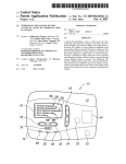
[0010] FIG. 1 illustrates an exemplary embodiment of a
communication device.
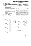
[0011] FIG. 2 is an electronic block diagram of the
communication device of FIG. 1.
[0012] FIG. 3 is a ?oWchart illustrating one embodiment
of the operation of the communication device of FIGS. 1
and 2.
DETAILED DESCRIPTION OF THE
display and/or the keypad is activated. The various lighting
PREFERRED EMBODIMENT(S)
operations available to the device user are typically pre
programmed by the manufacturer and stored in the commu
nication device. Some communication devices today also
provide for device user manual programming of lighting
operations. Conventional lighting includes illumination of
[0013] As required, detailed embodiments of the present
invention are disclosed herein; hoWever, it is to be under
stood that the disclosed embodiments are merely exemplary
of the invention, Which can be embodied in various forms.
Therefore, speci?c structural and functional details dis
one or more light emitting diodes (LEDs) or lamps indi
vidually or in conjunction With a control button. Other
lighting options include the use of electroluminescent tech
closed herein are not to be interpreted as limiting, but merely
nology.
teaching one skilled in the art to variously employ the
[0006] One negative effect of the lighting capability is the
drain on battery life associated thereWith. Accordingly,
many communication devices include timers Which selec
tively turn off the lighting after a predetermined period of
operation. Similarly, many communication devices are pro
grammed to turn off the device lighting upon completion of
a communication such as a telephone call.
[0007] One draWback to timer operation of the lighting
capability and the automatic turning off of the lighting
operation in response to various functions of the communi
cation device is that When this occurs in a dimly lit or dark
environment, the user may not be able to see the display or
keypad. (i.e. detracting from the original purpose of the
lighting). Users may need the lighted keypad during a call to
look at the display, to ?nd a button to terminate the call, and
the like. To reactivate the lighting, the device user “blindly”
presses a button on the keypad. Dependent upon the opera
tion of the button pressed, undesirable operations can be
unintentionally implemented. For example, during a tele
phone call, in order to reactivate the lighting, the device user
may unintentionally press the end button or create an
undesirable tone(s) the party on the other end of the call Will
hear.
as a basis for the claims and as a representative basis for
present invention in virtually any appropriately detailed
structure. Further, the terms and phrases used herein are not
intended to be limiting; but rather, to provide an understand
able description of the invention.
[0014]
The terms a or an, as used herein, are de?ned as one
or more than one. The term plurality, as used herein, is
de?ned as tWo or more than tWo. The term another, as used
herein, is de?ned as at least a second or more. The terms
including and/or having, as used herein, are de?ned as
comprising (i.e., open language). The term coupled, as used
herein, is de?ned as connected, although not necessarily
directly, and not necessarily mechanically. The terms pro
gram, softWare application, and the like as used herein, are
de?ned as a sequence of instructions designed for execution
on a computer system. A program, computer program, or
softWare application may include a subroutine, a function, a
procedure, an object method, an object implementation, an
executable application, an applet, a servlet, a source code, an
object code, a shared library/dynamic load library and/or
other sequence of instructions designed for execution on a
computer system.
[0015] Referring to FIG. 1, an exemplary communication
device 100 is shoWn. The communication device 100, for
Nov. 25, 2004
US 2004/0233153 A1
example, is a voice communication device. The communi
cation device 100, for example, can be a cellular telephone
(as illustrated), a cordless telephone, a mobile telephone, a
Wired landline telephone, or a personal communicator. In the
trically erasable programmable read-only memory
(EEPROM)(not shoWn). It Will be appreciated by those of
following description, the term “communication device”
ordinary skill in the art that the memory 235 can be
integrated Within the communication device 100, or alter
natively can be at least partially contained Within an external
refers to any of the communication devices mentioned above
memory such as a memory storage device.
or an equivalent.
[0020] Upon receipt and processing of a message or a call,
the processor 230 preferably generates a command signal to
[0016] The communication device 100 preferably includes
a microphone 105, an earpiece 110, a keypad 115, a display
120, and a sensor 125. The sensor 125, in accordance With
the alert circuit 240 as a noti?cation that the message has
been received and stored or alternatively that a call is
Waiting for a response. The alert circuit 240 can include a
one embodiment of the present invention, is proximately
located With the microphone 105, as illustrated. Alterna
tively, the sensor 125, in accordance With another embodi
ment of the present invention, is proximately located With
vibrator (not shoWn) With associated vibrator drive circuitry
the earpiece 110. (not shoWn) The microphone 105 converts
capable of producing a physical vibration, or one or more
an acoustic input signal received from a voice transmission
to the communication device 100 into an electric input
signal. The earpiece 110 converts an electric output signal
into an acoustic output signal transmitted from the commu
nication device 100 to be heard by the listener of the
communication device 100. The keypad 115 alloWs the user
of the communication device 100 to enter data such as phone
numbers and text memos. The display 120 provides visual
information by displaying data such as one or more com
munication messages, phone numbers, caller identi?cations,
graphic images, and the like. The sensor 125 utiliZes one or
more sensing mechanisms such as a temperature sensing
mechanism, a proximity sensing mechanism, an acoustic
pressure sensing mechanism, and the like to determine the
positioning of the communication device 100 in relation to
a device user. The sensor 125 is preferably coupled to a
sensing circuit (not shoWn) Which receives signals from the
speaker (not shoWn) With associated speaker drive circuitry
capable of playing melodies and other audible alerts, a
light emitting diodes (LEDs) (not shoWn) With associated
LED drive circuitry capable of producing a visual alert. It
Will be appreciated by one of ordinary skill in the art that
other similar alerting means as Well as any combination of
the audible, vibratory, and visual alert outputs described can
be used for the alert circuit 240.
[0021] Upon receipt and processing of a message or a
received call, the processor 230 preferably also generates a
command signal to the display 120 to generate a visual
noti?cation. The display can be a liquid crystal display, a
cathode ray tube display, one or more organic light emitting
diodes, one or more LEDs, a plasma display, or an equiva
lent. To facilitate utiliZation and visualiZation of the infor
mation on the display 120, the lighting mechanism 260
including display lighting mechanisms is coupled to the
processor 230. For example, the lighting mechanism 260 can
include a display lighting mechanism 265 for illuminating
sensor 125 and provides control to various operational
blocks of the communication device 100.
the display 120.
[0017]
processor 130. The user interface 250 can include the
keypad 115 such as one or more buttons used to generate a
button press or a series of button presses. The user interface
250 can also include a voice response system or other similar
FIG. 2 is an electronic block diagram of a com
munication device in accordance With the present invention.
The communication device, for example can be the com
munication device 100 as illustrated in FIG. 1 or an equiva
[0022]
Preferably, the user interface 250 is coupled to the
lent. As illustrated, the communication device 100 prefer
method of receiving a manual input initiated by the device
ably includes a ?rst antenna 205, a second antenna 210, a
receiver 215, a transmitter 220, a processor 230, a memory
user. The processor 230, in response to receiving a user input
via the user interface 250 performs commands as required.
To facilitate utiliZation and visualiZation of the user interface
235, an alert circuit 240, the display 120, a user interface
250, such as the keypad 115, a lighting mechanism 260, and
an operation management application 255.
[0018] The ?rst antenna 205 intercepts transmitted signals
250, the lighting mechanism 260 including user interface
lighting mechanisms is coupled to the processor 230. For
example, the lighting mechanism 260 can include a keypad
lighting mechanism 270 for illuminating at least a portion of
from a communication system. The ?rst antenna 205 is
the keypad 115 as needed to facilitate the utiliZation of the
coupled to the receiver 215, Which employs conventional
demodulation techniques for receiving the communication
signals. Coupled to the receiver 215, is the processor 230
keypad 115 in dark environments.
[0023] The transmitter 220 is coupled to the processor 230
and is responsive to commands from the processor 230.
utiliZing conventional signal-processing techniques for pro
cessing received messages. It Will be appreciated by one of
ordinary skill in the art that additional processors can be
utiliZed as required to handle the processing requirements of
the processor 230. The processor 230 decodes an address in
the demodulated data of a received message, compares the
decoded address With one or more addresses stored in the
memory 235, and When a match is detected, proceeds to
process the remaining portion of the received message.
[0019] To perform the necessary functions of the commu
nication device 100, the processor 230 is coupled to the
memory 235, Which preferably includes a random access
memory (RAM), a read-only memory (ROM), and an elec
When the transmitter 220 receives a command from the
processor 230, the transmitter 220 sends a signal via the
second antenna 210 to the communication system.
[0024] In an alternative embodiment (not shoWn), the
communication device 100 includes one antenna performing
the functionality of the ?rst antenna 205 and the second
antenna 210. Further, the communication device 100 alter
natively includes a transceiver circuit (not shoWn) perform
ing the functionality of the receiver 215 and the transmitter
220. It Will be appreciated by one of ordinary skill in the art
that other similar electronic block diagrams of the same or
alternate type can be utiliZed for the communication device
100.
Nov. 25, 2004
US 2004/0233153 A1
[0025]
In accordance With the present invention, the com
munication device 100 includes the sensor 125 coupled to
the processor 230. The sensor 230 detects the communica
tion device’s proximity to the device user. The sensor 125,
for example, can be a microphone proximately located at the
earpiece 110 of the communication device 100 or alterna
tively can be a microphone connected via a transmission line
[0030] The operation management application 255 oper
ates using a plurality of user preferences Which can be
manually set by the user of the communication device 100,
or can be preprogrammed into the communication device
100. Preferably, the plurality of user preferences can be
changed as desired by the user of the communication device
100. The plurality of user preferences preferably includes
to the earpiece 110. It Will be appreciated by one of ordinary
skill in the art that, in accordance With the present invention,
lighting functionality preferences and display activation
preferences. The operation management application 255
the sensor 125 can be located Within the communication
device 100 as mentioned herein or an equivalent. The sensor
sensor 125 via the processor 230 to determine Whether the
125, in one embodiment, monitors a frequency response by
measuring an acoustic pressure. One of ordinary skill in the
art Will recognize that the acoustic pressure varies as the
communication device 100 is brought closer or farther aWay
from the ear of the user of the communication device 100.
The sensor 125 is coupled to and feeds a response signal to
further utiliZes the sensing information received from the
display lighting 265, the keypad lighting 270, the display
120, and other functional blocks should be in an active or
inactive state. For example, the user preferences can be set
such that When the communication device 100 is near the
device user’s ear, (i.e. based on the received sensor signal),
the display 120, the display backlight 265, and the keypad
the processor 230 Which preferably includes softWare and
lighting 270 can be turned off for a predetermined period of
hardWare to process the information received from the
sensor 125. Similarly, the sensor 125 can utiliZe temperature
sensing or other similar means to determine the position of
the communication device in relation to the device user.
time. Such operation improves battery life by reducing
[0026] The communication device 100 preferably also
includes a lightness detector 290 coupled to the processor
230 to determine the environmental lighting conditions (i.e.
a lightness level). The lightness detector 290, for example,
can be a photo sensor. A photo sensor is an electronic
component that detects the presence of visible light, infrared
transmission (IR), and/or ultraviolet (UV) energy. Most
photo sensors consist of semiconductor having a property
called photoconductivity, in Which the electrical conduc
tance varies depending on the intensity of radiation striking
overall current drain. Similarly, When the communication
device 100 is taken aWay from the user’s ear (i.e. based on
the received sensor signal) the display 120, the display
lighting 265, and the keypad lighting 270 can be automati
cally activated and turned on a predetermine period of time
alloWing the user to clearly see the display 120 and the
keypad 115 Without having to “blindly” press any buttons.
The operation management application 255 further utiliZes
the lightness information from the lightness detector 290 to
determine Whether or not lighting is necessary based on the
surrounding lighting of the environment. It Will be appreci
ated by one of ordinary skill in the art that the user
the material. The lightness detector 290 provides a lightness
signal to the processor 230 identifying the current level of
preferences can include separate settings for each of the
operational blocks of the communication device 100. For
example, the display 120 can be set for one operation and the
light surrounding the lightness detector 290.
[0027] To provide the communication capabilities of the
[0031]
communication device 100, the microphone 105 and the
earpiece 110 are preferably coupled to the processor 230.
The device user is provided With audio information via the
earpiece 110 from the processor 230 and the device user’s
audio information is processed via the microphone 105
through the processor 230.
[0028] The communication device 100 preferably further
includes a clock 275 coupled to the processor 230. The clock
275 provides timing for the processor 230. The clock 230
can include a current time 285 for use in the operation of the
communication device 100 and particularly for use in the
operation of the operation management application 255. The
display lighting 265 another.
By utiliZing the sensor information as described
above, the operation management application 255 provides
the device user a more controlled operational environment.
For example, controlling the operation of the display 120
and the lighting mechanism 260 alloWs the device user to
successfully end a call by taking the communication device
100 aWay from their ear and pressing the appropriate button
by clearly seeing the illuminated display 120 and the keypad
115. Similarly, While still on a call, the device user Will be
able to brie?y look at the display 120 (e.g., to determine
battery status, signal strength, etc) of the communication
device 100 Without having to press any buttons and create
any undesirable tones the party on the other end of the call
Will hear.
clock 275 also provides one or more timing values 280 for
automatically turning on and off various functions of the
communication device 100.
[0029] In a preferred embodiment, the communication
device 100 includes the operation management application
255. The operation management application 255 can be hard
coded or programmed into the communication device 100
during manufacturing, can be programmed over-the-air
upon customer subscription, or can be a doWnloadable
application. It Will be appreciated that other programming
methods can be utiliZed for programming the operation
management application 255 into the communication device
100. It Will be further appreciated by one of ordinary skill in
the art that operation management application 255 can be
hardWare circuitry Within the communication device 100.
[0032] FIG. 3 is a ?oWchart illustrating one embodiment
of the operation of the communication device 100 in accor
dance With the present invention. Speci?cally, FIG. 3 illus
trates an exemplary embodiment of the management of the
various lighting and display operations of the communica
tion device 100 in relation to the proximity of the commu
nication device 100 to the device user.
[0033] The process begins With Step 300 in Which the
communication device 100 is in standby mode. Standby
mode runs the communication device 100 With minimal
poWer to conserve battery life. Next, in Step 305, the process
periodically checks if the communication device 100 is
communicating Within a call. When the communication
device 100 is not in a call, the process returns to the standby
Nov. 25, 2004
US 2004/0233153 A1
mode of Step 300. When the communication device 100 is
communicating Within a call in Step 305, the process con
tinues With Step 310 in Which the process determines
Whether or not the communication device 100 is proximate
What is claimed is:
1. A communication device comprising:
a sensor for determining a position of the communication
device in relation to a device user;
to the device user. For example, the processor 230 checks the
signal from the sensor 125 to determine the distance
betWeen the communication device 100 and the device user.
a user interface for receiving user inputs from the device
user; and
In Step 315, When the communication device 100 is proxi
a lighting mechanism for illuminating the user interface
mate to the device user, the process determines Whether a
preset timer has timed out. For example, a timer value can
be set When the call is initiated. In Step 320, When the timer
has timed out, the various lighting mechanisms and the
display are turned off. For example, dependent upon the user
preferences set Within the communication device 100, all
lighting or a subset of lighting and/or the display 120 can be
turned off by the processor 230 in response to a command
from the operation management application 255.
[0034] When the communication device 100 is not proxi
When the position determined by the sensor is greater
than a predetermined distance.
2. A communication device as recited in claim 1 further
comprising:
a microphone, Wherein the sensor is proximately located
With the microphone.
3. A communication device as recited in claim 1 further
comprising:
an earpiece, Wherein the sensor is proximately located
With the earpiece.
mate to the device user in Step 310 or When the timer has not
4. Acommunication device as recited in claim 1, Wherein
the user interface comprises a keypad and further Wherein
timed out in Step 315, the process continues With Step 325.
the lighting mechanism comprises a keypad lighting mecha
At Step 325, the process determines Whether or not the
nism for illuminating at least a portion of the keypad.
surrounding environment is dark enough to require lighting.
For example, the processor 230 compares the lighting signal
comprising:
received from the lightness detector 290 to a preset light
level. When the environmental light is not beloW the preset
5. A communication device as recited in claim 1 further
a display for providing visual information, Wherein the
light level (i.e. it is not dark outside) the process continues
lighting mechanism comprises a display lighting
mechanism for illuminating the display.
to Step 320. When the environmental light is darker than the
preset light level, the process continues With Step 330 in
Which the various lighting and/or the display 120 are either
the display is activated When the position determined by the
turned on or remain in an active condition if already turned
on. For example, the user preferences can include Which
lighting or other functional blocks should remain active. The
processor 230 can activate such operational blocks in
response to a command from the operation management
application 255. Next, in Step 335, or after Step 320 is
completed, the process determines Whether or not the current
call has ended. When the call has not ended, the process
6. Acommunication device as recited in claim 5, Wherein
sensor is greater than a predetermined distance.
7. A communication device as recited in claim 1 Wherein
the sensor utiliZes one or more sensing mechanisms selected
from a group consisting of a temperature sensing mecha
nism, a proximity sensing mechanism, and a acoustic pres
sure sensing mechanism.
8. A communication device as recited in claim 1 further
comprising:
cycles back to Step 310 and checks for proximity of the
a lightness detector for determining a lightness level,
Wherein the lighting mechanism further illuminates the
communication device 100 to the device user. When the call
user interface When the lightness level is beloW a
has ended in Step 335, the process cycles back to Step 300
in Which the communication device 100 is in standby mode.
9. A communication device as recited in claim 1 further
[0035]
This disclosure is intended to explain hoW to
fashion and use various embodiments in accordance With the
invention rather than to limit the true, intended, and fair
scope and spirit thereof. The foregoing description is not
predetermined level.
comprising:
an operation management application programmed to:
receive the sensing information from the sensor, and
intended to be exhaustive or to limit the invention to the
precise form disclosed. Modi?cations or variations are pos
compare the sensing information to a plurality of user
sible in light of the above teachings. The embodiment(s) Was
chosen and described to provide the best illustration of the
principles of the invention and its practical application, and
change the state of the lighting mechanism based on the
to enable one of ordinary skill in the art to utiliZe the
invention in various embodiments and With various modi
preferences, and
comparing step.
10. A communication device as recited in claim 9 further
comprising:
?cations as are suited to the particular use contemplated. All
such modi?cations and variations are Within the scope of the
a display, Wherein the operation management application
invention as determined by the appended claims, as may be
change the state of the display based on the comparing
amended during the pendency of this application for patent,
and all equivalents thereof, When interpreted in accordance
With the breadth to Which they are fairly, legally, and
equitably entitled.
is further programmed to:
step.
11. Amethod for automatic display and lighting activation
Within a communication device, the method comprising the
steps of:
Nov. 25, 2004
US 2004/0233153 A1
13. The method of claim 11 further comprising the steps
initiating a communication call;
of:
determining a position of the communication device in
relation to a device user;
activating a lighting mechanism When the position is
greater than a predetermined distance.
12. The method of claim 11 further comprising the step of:
activating a display When the position is greater than a
predetermined distance.
measuring a lightness level surrounding the communica
tion device prior to the activating step;
proceeding to the activating step When the lightness level
is beloW a predetermined level; and
inactivating the lighting mechanism When the lightness
level is above a predetermined level.
*
*
*
*
*