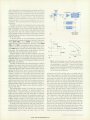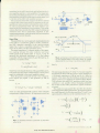
1
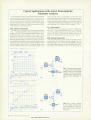
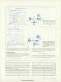
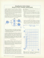
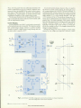
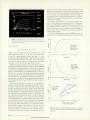
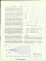
Thus, with the guard filter, the additional admittance be
comes a capacitance of Cg^L/ff) without a negative resis
tance and only the feedback of the output current compo
nent lags at high frequencies. Moreover, the additional
capacitance Cg, which appears in parallel with the load,
contributes to stability in the current-control mode.
The low-pass characteristics of the guard filter also func
tion to surround the center conductor of the triaxial cable
with an equipotential surface.
Current Ranging
Current ranging in each SMU is performed automatically
so that optimum accuracy is assured. This requires a spikeless current-range change scheme to prevent sudden
changes of output voltage during a range change that can
adversely affect a sensitive DUT.
A novel soft-switch scheme, shown in Fig. 4, is used in
the 4145A to control current ranging. By turning Ql on or
off, a range resistance of 10 Mil or 1 Gil can be selected. To
maintain the SMU output current at 10 nA when switching
range resistance from 1 Gil to 10 Mil, the voltage across the
range resistor (V0-VF) must change between +10V and
+0.1V as shown in Fig. 4. The maximum change rate of VF
versus time is determined by the response of the voltage
control loop. The range resistance value cannot change
faster than the response of the voltage control loop without
causing a transient change in V0. This is prevented by
applying to the gate of Ql a ramp voltage VG whose slew
rate is slow enough to allow VF to change in step with the
change in range resistance.
During this change, the output voltage V0 is kept nearly
constant by the voltage error amplifier. However, a small
To Power
Amplifier
Input
Vl,n+
1+ Error Amplifier
(a)
Fig. 5. characteris Schematic of the SMU voltage and current control amplifiers, (b) Output characteris
tics of the voltage and current control amplifiers.
18 HEWLETT-PACKARD JOURNAL OCTOBER 1982
© Copr. 1949-1998 Hewlett-Packard Co.