1
Freescale Semiconductor
Application Note
Document Number: AN2203
Rev. 2, 06/2007
MPC7450 RISC Microprocessor
Family Software Optimization Guide
This document provides information to programmers to
write optimal code for the MPC750, MPC7400, and
MPC7450 microprocessors that implement the PowerPC™
architecture, with particular emphasis on the MPC7450,
which is significantly different from previous designs. The
target audience includes performance-oriented writers of
both compilers and hand-coded assembly.
This document is a companion to the PowerPC Compiler
Writer’s Guide (CWG), with major updates for new
implementations not covered by that work; it is not a guide
for making a basic PowerPC compiler work. For compiler
guidelines, see the CWG. (However, many of the code
sequences suggested in the CWG are no longer optimal,
especially for the MPC7450.)
For details on the three different microprocessors and
compiler guidelines, consult the following references:
• MPC750 RISC Microprocessor Family User’s
Manual
• MPC7410 and MPC7400 RISC Microprocessor
User’s Manual
• MPC7450 RISC Microprocessor Family User’s
Manual
• The PowerPC Compiler Writer’s Guide (available on
the IBM web site)
© Freescale Semiconductor, Inc., 2001, 2007. All rights reserved.
Contents
1 Terminology and Conventions . . . . . . . . . . . . . . . . . . .2
2 Processor Overview . . . . . . . . . . . . . . . . . . . . . . . . . . .4
3 Overview of Target Microprocessors . . . . . . . . . . . . . .7
4 MPC7450 Microprocessor Details . . . . . . . . . . . . . . .16
5 Dispatch Considerations . . . . . . . . . . . . . . . . . . . . . . .26
6 Issue Queue Considerations . . . . . . . . . . . . . . . . . . . .29
7 Completion Queue . . . . . . . . . . . . . . . . . . . . . . . . . . .31
8 Numeric Execution Units . . . . . . . . . . . . . . . . . . . . . .32
9 FPU Considerations . . . . . . . . . . . . . . . . . . . . . . . . . .33
10 Memory Subsystem (MSS) . . . . . . . . . . . . . . . . . . . . .42
11 Microprocessor Application to Optimal Code . . . . . .44
12 Optimized Code Sequences . . . . . . . . . . . . . . . . . . . .52
Appendix AMPC7450 Execution Latencies . . . . . . . . . . . . .60
Appendix BRevision History . . . . . . . . . . . . . . . . . . . . . . . .75
Terminology and Conventions
Table 1 lists the three main processors referenced in this document and their derivatives. The derivative
list is not necessarily complete and is subject to change.
Table 1. Microarchitecture List
First Implementation
1
Derivatives (Similar Devices)
MPC750
MPC740, MPC745, MPC755
MPC7400
MPC7410
MPC7450
MPC7441, MPC7451
Terminology and Conventions
This section provides an alphabetical glossary of terms used in this document. Because of the differences
in the MPC7450, many of these definitions differ slightly from those for previous processors that
implement the PowerPC architecture, particularly with respect to dispatch, issue, finishing, retirement, and
write-back:
• Branch prediction—The process of guessing the direction or target of a branch. Branch direction
prediction involves guessing whether a branch will be taken. Target prediction involves guessing
the target address of a bclr branch. The PowerPC architecture defines a means for static branch
prediction as part of the instruction encoding.
• Branch resolution—The determination of whether a branch prediction is correct. If it is, the
instructions after the predicted branch that may have been speculatively executed can complete
(see completion). If the prediction is incorrect, instructions on the mispredicted path and any results
of speculative execution are purged from the pipeline and fetching continues from the correct path.
• Complete—An instruction is in the complete stage after it executes and makes its results available
for the next instruction (see finish). At the end of the complete stage, the instruction is retired from
the completion queue (CQ). When an instruction completes, it is guaranteed that this instruction
and all previous instructions can cause no exceptions.
• Dispatch—The dispatch stage decodes instructions supplied by the instruction queue, renames any
source/target operands, determines to which issue queue each non-branch instruction is dispatched,
and determines whether the required space is available in both that issue queue and the completion
queue.
• Fall-through folding (branch fall-through)—Removal of a not-taken branch. On the MPC7450,
not-taken branch instructions that do not update LR or CTR can be removed from the instruction
stream if the branch instruction is in IQ3–IQ7.
• Fetch—The process of bringing instructions from memory (such as a cache or system memory)
into the instruction queue.
• Finish—An executed instruction finishes by signaling the completion queue that execution is
complete and results are available to subsequent instructions. For most execution units, finishing
occurs at the end of the last cycle of execution; however, FPU, IU2, and VIU2 instructions finish
at the end of a single-cycle finish stage after the last cycle of execution.
• Folding (branch folding)—The replacement of a branch instruction and any instructions along the
not-taken path with target instructions when a branch is either taken or predicted as taken.
MPC7450 RISC Microprocessor Family Software Optimization Guide, Rev. 2
2
Freescale Semiconductor
Terminology and Conventions
•
•
•
•
•
•
•
•
•
•
•
•
•
Issue—The pipeline stage reads source operands from rename registers and register files. This
stage also assigns and routes instructions to the proper execution unit.
Latency— The number of clock cycles necessary to execute an instruction and make the results of
that execution available to subsequent instructions.
Pipeline—In the context of instruction timing, refers to the interconnection of the stages. The
events necessary to process an instruction are broken into several cycle-length tasks so work can
be performed on several instructions simultaneously—analogous to an assembly line. As an
instruction is processed, it passes from one stage to the next. When it does, the stage becomes
available for the next instruction.
Although an individual instruction can take many cycles to make results available (see latency),
pipelining makes it possible to overlap processing so that the throughput (number of instructions
processed per cycle) is increased.
Program order—The order of instructions in an executing program; more specifically, the original
order in which program instructions are fetched into the instruction queue from the cache.
Rename registers—Temporary buffers for holding results of instructions that have finished
execution but have not completed.
Reservation station—A buffer between the issue and execute stages that allows instructions to be
issued even though the results of other instructions on which the issued instruction may depend are
not available.
Retirement—Removal of a completed instruction from the CQ.
Speculative instruction—Any instruction that is currently behind an unresolved older branch.
Stage—An element in the pipeline where specific actions are performed, such as decoding an
instruction, performing an arithmetic operation, or writing back the results. Typically, the latency
of a stage is one processor clock cycle. Some events, such as dispatch, writeback, and completion,
happen instantaneously and may be thought to occur at the end of a stage.
An instruction can spend multiple cycles in one stage. For example, an integer multiply takes
multiple cycles in the execute stage. When this occurs, subsequent instructions may stall.
An instruction can also occupy more than one stage simultaneously, especially in the sense that a
stage can be viewed as a physical resource—for example, when instructions are dispatched they
are assigned a place in the CQ at the same time they are passed to the issue queues.
Stall—An instruction cannot proceed to the next stage.
Superscalar—A superscalar processor can issue multiple instructions concurrently from a
conventional linear instruction stream. In a superscalar implementation, multiple instructions can
be in the execute stage at the same time.
Throughput—The number of instructions that are processed per cycle. For example, a series of
mulli instructions have a throughput of one instruction per clock cycle.
Write-back—Write-back (in the context of instruction handling) occurs when a result is written
into the architecture-defined registers (typically the GPRs, FPRs, and VRs). On the MPC7450,
write-back occurs in the clock cycle after the completion stage. Results in the write-back buffer
cannot be flushed. If an exception occurs, results from previous instructions must write back before
the exception is taken.
MPC7450 RISC Microprocessor Family Software Optimization Guide, Rev. 2
Freescale Semiconductor
3
Processor Overview
2
Processor Overview
This section describes the high-level differences between the MPC750, the MPC7400, and the MPC7450.
Also, it describes the pipeline differences in these three processors.
2.1
High-Level Differences
To achieve a higher frequency, the MPC7450 design reduces the number of logic levels per cycle, which
extends the pipeline. More resources are added to reduce the effect of the pipeline length on performance.
These pipeline length and resource changes can make an important difference in code scheduling. Table 2
describes high-level differences between MPC750, MPC7400, and MPC7450 processors.
Table 2. High-Level Differences
Microprocessor Feature
MPC750
MPC7400
MPC7450
Basic Pipeline Functions
Logic inversions per cycle
28
28
18
Pipeline stages up to first execute
3
3
5
Minimum total pipeline length
4
4
7
2 + 1 branch
2 + 1 branch
3 + 1 branch
Pipeline maximum instruction throughput
Pipeline Resources
Instruction queue size
6
6
12
Completion queue size
6
8
16
6, N/A, 6
6, 6, 6
16, 16, 16
BTIC, BHT
BTIC, BHT
BTIC, BHT, LinkStack
BTIC size, associativity
64-entry, 4-way
64-entry, 4-way
128-entry, 4-way
BTIC instructions/entry
2
2
4
512-entry
512-entry
2048-entry
N/A
N/A
8
Unresolved branches supported
2
2
3
Branch taken penalty (BTIC hit)
0
0
1
Minimum branch mispredict penalty (cycles)
4
4
6
1 IU1, 1 IU1/IU2,
1 SRU,
1 LSU
3 IU1,
1 IU2/SRU,
1 LSU
Rename register (integer, vector, FP)
Branch Prediction Resources/Features
Branch prediction structures
BHT size
Link stack depth
Available Execution Units
Integer execution units
Floating-point execution units
Vector execution units
1 IU1, 1 IU1/IU2,
1 SRU,
1 LSU
1 double-precision FPU 1 double-precision FPU 1 double-precision FPU
N/A
2-issue to VPU and
VALU (VALU has VSIU,
VCIU, VFPU subunits)
2-issue to any
2 vector units (VSIU,
VPU, VCIU, VFPU)
MPC7450 RISC Microprocessor Family Software Optimization Guide, Rev. 2
4
Freescale Semiconductor
Processor Overview
Table 2. High-Level Differences (continued)
Microprocessor Feature
MPC750
MPC7400
MPC7450
2, N/A, 2
2, 2, 2
3, 3, 4
IU1 (add, shift, rotate, logical)
1
1
1
IU2: multiply (32-bit)
6
6
4
IU2: divide
19
19
23
FPU: single (add, mul, madd)
3
3
5
FPU: single (divide)
17
17
21
FPU: double (add)
3
3
5
FPU: double (mul, madd)
4
3
5
FPU: double (divide)
31
31
35
VSIU
N/A
1
1
VCIU
N/A
3
4
VFPU
N/A
4
4
VPU
N/A
1
2
Typical Execution Unit Latencies
Data cache load hit (integer, vector, float)
L1 Instruction Cache/Data Cache Features
L1 cache size (instruction, data)
32-Kbyte, 32-Kbyte
L1 cache associativity (instruction, data)
8-way, 8-way
L1 cache line size
32 bytes
L1 cache replacement algorithm
Pseudo-LRU
Number of outstanding data cache misses
(load/store)
1 (load or store)
8 (any combination
load/store)
5 load/1 store
Additional On-Chip Cache Features
Additional on-chip cache level
None
None
L2
Additional on-chip cache size
N/A
N/A
256-Kbyte
Additional on-chip cache associativity
N/A
N/A
8-way
Additional on-chip cache line size
N/A
N/A
64 bytes
(2 sectors per line)
Additional on-chip cache replacement algorithm
N/A
N/A
Pseudo-random
Off-Chip Cache Support
Off-chip cache level
L2
Off-chip cache size
Off-chip cache associativity
Off-chip cache line size/sectors per line
Off-chip cache replacement algorithm
L3
256-Kbyte, 512-Kbyte,
1-Mbyte
512-Kbyte, 1-Mbyte,
2-Mbyte
1-Mbyte, 2-Mbyte
2-way
2-way
8-way
64B/2, 64B/2, 128B/4
32B/1, 64B/2, 128B/4
64B/2, 128B/4
FIFO
FIFO
Pseudo-random
MPC7450 RISC Microprocessor Family Software Optimization Guide, Rev. 2
Freescale Semiconductor
5
Processor Overview
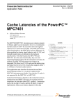
2.2
Pipeline Differences
The MPC7450 instruction pipeline differs significantly from the MPC750 and MPC7400 pipelines.
Figure 1 shows the basic pipeline of the MPC750/MPC7400 processors.
Branch
IU1
LSU
F
F
F
BE
D
D
E
E0
WB
E1
WB
Figure 1. MPC750 and MPC7400 Pipeline Diagram
Table 3 briefly explains the pipeline stages.
Table 3. MPC750/MPC7400 Pipeline Stages
Pipeline Stage
Fetch
Branch execution
Abbreviation
F
BE
Dispatch
D
Execute
E, E0, E1, ...
Write-back
WB
Comment
Read from instruction cache
Execute branch and redirect fetch if needed
Decode, dispatch to execution units, assigned to rename register, register file read
Instruction execution and completion
Architectural update
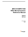
Figure 2 shows the basic pipeline of the MPC7450 processor, and Table 4 briefly explains the stages.
Branch
IU1
LSU
F1
F1
F1
F2
F2
F2
BE
D
D
I
I
E
E0
C
E1
WB
E2
C
WB
Figure 2. MPC7450 Pipeline Diagram
Table 4 briefly explains the MPC7450 pipeline stages.
MPC7450 RISC Microprocessor Family Software Optimization Guide, Rev. 2
6
Freescale Semiconductor
Overview of Target Microprocessors
Table 4. MPC7450 Pipeline Stages
Pipeline Stage
Abbreviation
Comment
Fetch1
F1
First stage of reading from instruction cache
Fetch2
F2
Second stage of reading from instruction cache
Branch execute
BE
Execute branch and redirect fetch if needed
Dispatch
D
Decode, dispatch to IQs, assigned to rename register
Issue
I
Issue to execution units, register file read
Execute
E, E0, E1, ...
Instruction execution
Completion
C
Instruction completion
Write-back
WB
Architectural update
The MPC7450 pipeline is longer than the MPC750/MPC7400 pipeline, particularly in the primary load
execution part of the pipeline (3 cycles versis 2 cycles). Faster processor performance often requires
designs to operate at higher clock speeds. Clock speed is inversely related to the work performance of the
processor. Therefore, higher clock speeds imply less work to be performed per cycle, which necessitates
longer pipelines. Also, increased density of the transistors on the chip has enabled the addition of
sophisticated branch-prediction hardware, additional processor resources, and out-of-order execution
capability. This industry trend should continue for at least one more microprocessor generation. The longer
pipelines yield a processor more sensitive to code selection and ordering. Because hardware can add
additional resources and out-of-order processing ability to reduce this sensitivity, the hardware and the
software must work together to achieve optimal performance.
3
Overview of Target Microprocessors
This section provides a high-level overview of the three target microprocessors, with first-order details that
are useful in developing a compiler model of the microprocessor.
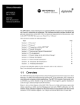
3.1
MPC750 Microprocessor
Figure 3 shows a functional block diagram of the MPC750.
MPC7450 RISC Microprocessor Family Software Optimization Guide, Rev. 2
Freescale Semiconductor
7
8
+ x ÷
+
Reorder Buffer
(6-Entry)
Completion Unit
Integer Unit 2
Integer Unit 1
32-Bit
Reservation Station
Reservation Station
2 Instructions
Additional Features
• Time Base Counter/Decrementer
• Clock Multiplier
• JTAG/COP Interface
• Thermal/Power Management
• Performance Monitor
DTLB
SRs
(Original)
DBAT
Array
Data MMU
32-Bit
CR
System Register
Unit
Reservation Station
Tags
PA
32-Kbyte
D Cache
64-Bit
17-Bit L2 Address Bus
64-Bit L2 Data Bus
Data Load Queue
L1 Castout Queue
64-Bit
64-Bit
Tags
32-Kbyte
I Cache
128-Bit
(4 Instructions)
L2CR
L2 Tags
Not in the MPC740
L2 Castout Queue
L2 Controller
FPSCR
+ x ÷
Floating-Point
Unit
Reservation Station
L2 Bus Interface
Unit
Rename Buffers
(6)
FPR File
ITLB
IBAT
Array
Instruction MMU
SRs
(Shadow)
60x Bus Interface Unit
Instruction Fetch Queue
Store Queue
+
(EA Calculation)
Load/Store Unit
64-Bit
32-Bit
CTR
LR
Reservation Station
(2-Entry)
64-Bit
(2 Instructions)
BHT
BTIC
64-Entry
32-Bit Address Bus
64-Bit Data Bus
EA
Rename Buffers
(6)
GPR File
Dispatch Unit
Instruction Queue
(6-Word)
Fetcher
Branch Processing
Unit
Instruction Unit
Overview of Target Microprocessors
Figure 3. MPC750 Microprocessor Block Diagram
MPC7450 RISC Microprocessor Family Software Optimization Guide, Rev. 2
Freescale Semiconductor
Overview of Target Microprocessors
Instructions are fetched from the instruction cache and placed into a six-entry IQ. When the fetch pipeline
is fully utilized, as many as four instructions can be fetched to the IQ during each clock cycle, subject to
cache block wrap restrictions.
3.1.1
Dispatch
The bottom two IQ entries are available for dispatch, which involves the following operations:
• Renaming—Six rename registers are available for integer operation and six more are available for
floating-point operations.
• Dispatching—A reservation station must be available for the correct execution unit.
• CQ check—An entry must be available in the six-entry CQ.
• Branch check—A branch instruction must have executed before being dispatched. Section 3.1.4,
“Branches,” provides additional information.
3.1.2
Execution
An instruction in the bottom of a reservation station is available for execution. Execution involves the
following operations:
• Busy check—The unit must be available. For example, some units are not fully pipelined.
• Operand check—All source operands must be available before any execution can start.
• Serialization check—If the instruction is execution serialized, it must wait to become the oldest
instruction in the machine (bottom of the CQ entry) before it can start execution.
3.1.3
Completion
The bottom two CQ entries are available for completion, which involves the following operations:
• Finish check—Only instructions that have finished or are in the last stage of execution are eligible
for finishing.
• Rename check—The MPC750 can write back only two rename registers per cycle. Some
instructions, such as a load-with-update, have multiple renamed targets. If a load-with-update and
an add instruction are in the bottom two CQ entries, the add cannot complete because the
load-with-update already requires two rename-register-writeback slots for the subsequent cycle.
NOTE
In the MPC750, execution and completion can occur simultaneously for
single-cycle execution instructions.
3.1.4
Branches
Branches are handled differently from other instructions. Branch instructions must be executed by the
branch unit before they can be dispatched. The BPU searches the six-entry IQ for the oldest unexecuted
branch and executes it. If the branch instruction does not update the architectural state by setting the link
or count register, it is eligible for folding. In branch execution, the instruction is folded immediately if the
branch is taken. In this case, folding removes the branch instruction from the IQ, so the branch instruction
MPC7450 RISC Microprocessor Family Software Optimization Guide, Rev. 2
Freescale Semiconductor
9
Overview of Target Microprocessors
does not reach the dispatcher. If the branch is not taken, the dispatcher must dispatch the branch. However,
the branch is not allocated in the CQ, so no completion is required either.
If the branch is either b or bc, a taken branch can get instructions from the BTIC. The BTIC lookup is
automatically performed based on the instruction address of the executing branch, and produces
instructions starting at the branch target address. The BTIC supplies two instructions for that cycle, as
opposed to the normal four from the instruction cache. Indirect branches, such as bcctr or bclr, do not get
instructions from the BTIC. Thus, a taken branch incurs a one-cycle fetch bubble when it executes.
3.1.5
MPC750 Compiler Model
A good compiler scheduling model for the MPC750 includes the two-instruction-per-clock-cycle dispatch
limitation, a base model of the CQ with a maximum of six instructions with
two-instruction-per-clock-cycle completion limitation, and execution units—SRU, IU1, IU2, FPU, and
LSU with typical unit execution latencies as given in Table 1.
A full model incorporates full table-driven latency/throughput/serialization specifications given
instruction by instruction in Appendix A, “MPC7450 Execution Latencies.” The notion of reservation
stations (particularly, the second LSU reservation station) should be added. Rename registers limitations
for the GPRs are also needed to allow more accurate modeling of the load/store-with-update instructions.
3.2
MPC7400 Microprocessor
The MPC7400 microprocessor is similar to the MPC750 microprocessor. The primary differences include
the following attributes:
• Eight-entry CQ (although rename registers are still limited to six)
• Vector units (and instructions), which implement the Altivec extensions to the PowerPC
architecture
• Better latency and pipelining on double-precision floating-point operations
• Increased pipelining of load/store misses in the LSU
Figure 4 shows a functional block diagram of the MPC7400.
3.2.1
Vector Unit
The MPC7400 can dispatch two vector instructions per cycle: one to the VPU and one to the VALU. The
VPU is a single-cycle execution unit unlike the VALU that has three independent subunits, each with
different latencies, as follows:
• The VSIU subunit handles simple integer and logical operations with single-cycle latency per
instruction.
• The VCIU handles complex integer instructions (mostly multiplies) with a latency of three clocks
and a throughput of one instruction per cycle.
• The VFPU subunit handles vector floating-point instructions with a latency of four clocks and a
throughput of one instruction per cycle.
The VALU can initiate one instruction per cycle to any of these three subunits. After execution begins,
these subunits are fully independent.
MPC7450 RISC Microprocessor Family Software Optimization Guide, Rev. 2
10
Freescale Semiconductor
Freescale Semiconductor
Completion Queue
(8-Entry)
Completion Unit
VSCR
Vector ALU
Vector
Permute
Unit
VR File
18-Bit L2 Address Bus
64-Bit L2 Data Bus
Ability to complete up
to two instructions per clock
+ x ÷
Integer
Unit 2
Reservation
Station
L2 Controller
L2 Tags
L2 Data
Transaction L2CR
32-Bit
CTR
LR
Vector
Touch
Queue
6 Rename
Buffers
GPR File
32-Bit
L2 Castout
IBAT
Array
DBAT
Array
Load/Store Unit
+ (EA Calculation)
Finished Load Fold
Stores
Reservation
Station (2-Entry)
128-Entry
DTLB
SRs
(Original)
Data MMU
128-Entry
ITLB
SRs
(Shadow)
Instruction MMU
Tags
32-Kbyte
I Cache
128-Bit
(4 Instructions)
Instruction
Instruction
Reload Queue Reload Table
Memory Subsystem
Data Reload Data Reload
Queue
Table
64-Bit
6 Rename
Buffers
FPSCR
+ x ÷
FloatingPoint Unit
Reservation
Station
32-Kbyte
Tags D Cache
FPR File
Completed
L1
Stores Operations 64-Bit
PA
EA
Bus Interface Unit
L2 Miss
Data
Transaction
32-Bit
System
Register Unit
Reservation
Station
64-Bit (2 Instructions)
Dispatch Unit
BHT
(512-Entry)
BTIC
(64-Entry)
Branch Processing
Unit
32-Bit Address Bus
64-Bit Data Bus
+
Integer
Unit 1
Reservation
Station
Instruction Queue
(6-Word)
128-Bit
6 Rename
Buffers
128-Bit
VSIU VCIU VFPU
Reservation
Station
Reservation
Station
2 Instructions
Additional Features
• Time Base Counter/Decrementer
• Clock Multiplier
• JTAG/COP Interface
• Thermal/Power Management
• Performance Monitor
Fetcher
Instruction Unit
Overview of Target Microprocessors
Figure 4. MPC7400 Microprocessor Block Diagram
MPC7450 RISC Microprocessor Family Software Optimization Guide, Rev. 2
11
Overview of Target Microprocessors
3.2.2
MPC7400 Compiler Model
A good compiler scheduling model for the MPC7400 includes the dispatch limitations of two instructions
per clock, a base model of the CQ with a maximum of eight instructions, the completion limitation of two
instructions per clock, and the execution units—SRU, IU1, IU2, FPU, VPU, VALU (VSIU, VCIU, VFPU),
and LSU with typical execution unit latencies as given in Appendix A, “MPC7450 Execution Latencies.”
A full model incorporates full table-driven latency/throughput/serialization specifications given
instruction by instruction in Appendix A, “MPC7450 Execution Latencies.” The concept of reservation
stations (especially the second LSU reservation station) should be added. The rename registers limitations
are much more important than in the MPC750, since the number of rename registers (six) does not match
the number of completion entries (eight).
3.3
MPC7450 Microprocessor
Different resource sizes, issue queues, and the splitting of the completion and execution stages are the main
differences between the MPC7450 and the MPC750/MPC7400 models. Also, the MPC7450 can dispatch
up to three instructions per cycle (compared to two on the MPC7400) and can complete a maximum of
three instructions per cycle (compared to two on the MPC7400).
With the addition of extra integer units, the MPC7450 has more integer computing capacity available for
scheduling. The MPC7450 has three single-cycle IUs (IU1a, IU1b, IU1c) that execute all integer
(fixed-point) instructions (addition, subtraction, logical operations—AND, OR, shift, and rotate) except
multiply, divide, and move to/from special-purpose register instructions. Note that all IU1 instructions
execute in one cycle, except for some instructions like tw[i] and sraw[i][.], which take two. In addition, it
has one multiple-cycle IU (IU2) that executes miscellaneous instructions including the CR logical
operations, integer multiplication and division instructions, and move to/from special-purpose register
instructions. The issue requirements for the vector subunits are also improved which is described in detail
in Section 6.2, “Vector Issue Queue (VIQ).”
The longer pipeline of the MPC7450 is more sensitive to branch mispredictions. Taken branches of
MPC7450 cause a single-cycle fetch bubble, whereas most taken branches on the MPC750/MPC7400
were nearly free. The MPC7450 also changes the load-use latency, which is critical to adjust to achieve
best performance on many applications. Also, serialized instructions are more costly in terms of
performance on this microprocessor.
Figure 5 is a functional block diagram of the MPC7450.
MPC7450 RISC Microprocessor Family Software Optimization Guide, Rev. 2
12
Freescale Semiconductor
Freescale Semiconductor
18-Bit
Address
Bus Accumulator
Line Block 0/1
Tags Status
64-Bit Data
(8-Bit Parity)
Completes up to three instructions per clock cycle
Completion Queue
(16-Entry)
LR
BHT (2048-Entry)
Vector
FPU
External SRAM
(1 or 2 Mbyte)
L3CR
VR File
x
32-Bit
÷
Integer
Unit 2
Reservation
Stations (2)
Bus Store Queue
Push
36-Bit Address Bus
Bus Accumulator
Castout
Queue
(9)
32-Bit
32-Bit
16 Rename
Buffers
128-Entry
ITLB
Completed
Stores
L1 Push
Finished
Stores
Load Miss
L1 Castout
+ (EA Calculation)
Vector Touch Engine
Load/Store Unit
Reservation
Stations (2-Entry)
64-Bit Data Bus
L2 Store Queue (L2SQ)
Snoop Push/
L1 Castouts
Interventions
(4)
EA
FPR File
Tags
64-Bit
FPSCR
+x÷
FloatingPoint Unit
Reservation
Stations (2)
Instruction Fetch (2)
Cacheable Store
Request (1)
L1 Load Miss (5)
L1 Service Queues
L1 Store Queue
(LSQ)
L1 Load Queue (LLQ)
64-Bit
32-Kbyte
I Cache
32-Kbyte
D Cache
Tags
128-Bit (4 Instructions)
16 Rename
Buffers
PA
128-Entry
DTLB
DBAT Array
SRs
(Original)
Data MMU
IBAT Array
SRs
(Shadow)
Instruction MMU
256-Kbyte Unified L2 Cache/Cache Controller
Line Block 0 (32-Byte)
Block 1 (32-Byte)
Tags Status
Status
Memory Subsystem
Integer
Integer
Integer
Unit
122
Unit
Unit
(3)
+++
GPR File
Vector
Touch
Queue
FIQ
(2-Entry/1-Issue)
Instruction Queue
(12-Word)
Reservation
Reservation
Reservation
Station
Station
Station
Dispatch
Unit
System Bus Interface
L2 Prefetch (3)
128-Bit
16 Rename
Buffers
128-Bit
Reservation
Station
VIQ
(4-Entry/2-Issue)
CTR
BTIC (128-Entry)
Fetcher
GIQ
(6-Entry/3-Issue)
Instruction Unit
Branch Processing Unit
L3 Cache Controller
+
X
Completion Unit
Vector
Integer
Unit 1
Vector
Integer
Unit 2
Vector
Permute
Unit
Reservation
Station
Reservation
Station
Reservation
Station
3 Instructions
Additional Features
• Time Base Counter/Decrementer
• Clock Multiplier
• JTAG/COP Interface
• Thermal/Power Management
• Performance Monitor
Overview of Target Microprocessors
Figure 5. MPC7450 Microprocessor Block Diagram
MPC7450 RISC Microprocessor Family Software Optimization Guide, Rev. 2
13
Overview of Target Microprocessors
3.3.1
Dispatch
The bottom three IQ entries are available for dispatch, which involves the following:
• Renaming—16 rename registers are available for each of the integer, floating-point, and vector
operations.
• Dispatching—Available issue queue entries must be available for each dispatched instruction.
• CQ check—An entry must be available in the 16-entry CQ.
• Branch check—A branch instruction must execute before it is dispatched. Section 3.3.8,
“Branches,” provides more information on branching.
3.3.2
Issue Queues
Each issue queue handles issuing slightly differently and is described separately as follows.
3.3.3
General-Purpose Issue Queue
The six-entry general-purpose issue queue (GIQ in Figure 5) handles integer instructions, including all
load/store instructions. The GIQ accepts as many as three instructions from the dispatch unit each cycle.
All IU1s, IU2, and LSU instructions (including floating-point and AltiVec loads and stores) are dispatched
to the GIQ. Instructions can be issued out-of-order from the bottom three GIQ entries (GIQ2–GIQ0). An
instruction in GIQ1 destined to one of the IU1s does not have to wait for an instruction stalled in GIQ0
that is behind a long-latency integer divide instruction in the IU2. The primary check is that a reservation
station must be available.
3.3.4
Floating-Point Issue Queue
The two-entry floating-point issue queue (FIQ) can accept one dispatched instruction per cycle for the
FPU, and if an FPU reservation station is available, it can also issue one instruction from the bottom FIQ
entry.
3.3.5
Vector Issue Queue
The four-entry vector issue queue (VIQ) accepts as many as two vector instructions from the dispatch unit
each cycle. All AltiVec instructions (other than load, store, and vector touch instructions) are dispatched
to the VIQ. The bottom two entries are allowed to issue as many as two instructions to the four AltiVec
execution unit’s reservation stations, but unlike the GIQ, instructions in the VIQ cannot be issued out of
order. The primary check determines if a reservation station is available.
NOTE
The VIQ can issue to any two vector units, unlike the MPC7400. For
example, the MPC7450 can issue to the VSIU and VCIU simultaneously,
whereas the MPC7400 allows pairing between the VPU and one of the other
three VALU subunits.
MPC7450 RISC Microprocessor Family Software Optimization Guide, Rev. 2
14
Freescale Semiconductor
Overview of Target Microprocessors
3.3.6
Execution
The instruction in the bottom of the reservation station is available for execution. Execution involves the
following:
• Busy check—The unit must not be busy. For example, some units are not fully pipelined and so
cannot accept a new instruction on every clock.
• Operand check—All source operands must be available before any execution can start.
• Serialization check—If the instruction is execution serialized, it must wait to become the oldest
instruction in the machine (bottom of the CQ entry) before it can start execution.
The MPC7450 has two more IUs than the MPC750/MPC7400. However, the integer unit capabilities have
changed slightly from the MPC750/MPC7400 to the MPC7450, as shown in Table 5. Appendix A,
“MPC7450 Execution Latencies,” compares latencies between MPC750, MPC7400, and MPC7450 for
various instructions.
Table 5. MPC750/MPC7400 vs. MPC7450 Integer Unit Breakdown
Instruction Class
MPC750/MPC7400
MPC7450
IU1 or IU2
IU1 (any of 3)
mul, div
IU2
IU2
mtspr, mfspr, CR logical, and other miscellaneous instructions
SRU
IU2
add, subtract, logical, shift/rotate
3.3.7
Completion
The bottom three CQ entries are available for retiring instructions. Completion involves the following
operations:
• Finish check—Only instructions that finish can complete (except store instructions, which finish
and complete simultaneously to allow pipelining).
• Rename check—An MPC7450 can write back only three rename registers per cycle. Some
instructions, such as load-with-update, have multiple renamed targets. If a load-with-update is
followed by two adds, only the load-with-update and the first add can complete at the same time
(although all three instructions are finished executing). The load-with-update requires two of the
three rename-register-writeback resources. Due to this resource constraint, the second add waits
until the second cycle is completed.
3.3.8
Branches
Branches are handled differently from other instructions. Branch instructions must be executed by the
branch unit before they can be dispatched. The BPU searches the bottom eight entries of the IQ for the
oldest unexecuted branch and executes it. A branch instruction is eligible for folding if it does not update
the architectural state by setting the link or count register. In branch execution, the instruction is folded
immediately if the branch is taken. In this case, folding removes the branch instruction from the IQ, so the
branch instruction does not reach the dispatcher. If the branch is not taken, the dispatcher must dispatch
the branch, and the branch is placed in the CQ.
MPC7450 RISC Microprocessor Family Software Optimization Guide, Rev. 2
Freescale Semiconductor
15
MPC7450 Microprocessor Details
NOTE
Note that in the MPC750, the dispatched (fall-through) foldable branches
are not allocated in the CQ.
If the branch is either b or bc, a taken branch can get instructions from the BTIC. The BTIC lookup is
automatically performed based on the instruction address of the executing branch and produces
instructions starting at the branch target address. Taken branches have a minimum one-cycle fetch bubble,
since the BTIC supplies four instructions on the following cycle. Indirect branches such as bcctr or bclr
do not get instructions from the BTIC. Thus, taken branches incur a two-cycle fetch bubble when they
execute. From a code performance point of view, the need for biasing the branch to be fall-through has
increased to avoid the 1- or 2-cycle fetch bubble of a taken branch. The longer pipeline makes the
MPC7450 more sensitive to branch misprediction than earlier designs.
3.3.9
MPC7450 Compiler Model
A good scheduling model for the MPC7450 should take into account the dispatch limitations of the three
instructions per cycle, the 16-entry CQ’s completion limitation of three instructions per cycle, and the
various execution units with the latencies discussed earlier.
A full model would also incorporate the full table-driven latency/throughput/serialization specifications
for each instruction listed in Appendix A, “MPC7450 Execution Latencies.” The usage and availability of
reservation stations and rename registers should also be incorporated. Finally, attention should be given to
the issue limitations of the various issue queues—for example, it is important to note that AltiVec
instructions must be issued in-order out of the vector issue queue. This means that a few poorly scheduled
instructions can potentially stall the entire vector unit for many cycles.
4
MPC7450 Microprocessor Details
This section describes many architectural details of the MPC7450 and gives examples of the pipeline
behavior. These attributes are also described in the MPC7450 RISC Microprocessor Family User’s
Manual.
4.1
Fetch/Branch Considerations
The following is a list of branch instructions and the resources required to avoid stalling the fetch unit in
the course of branch resolution:
• The bclr instruction requires LR availability for resolution. However, it uses the link stack to
predict the target address in order to avoid stalling the fetch unit.
• The bcctr instruction requires CTR availability.
• The branch conditional on counter decrement and the CR condition require CTR availability, or the
CR condition must be false.
• A fourth conditional branch instruction cannot be executed following three unresolved predicted
branch instructions.
MPC7450 RISC Microprocessor Family Software Optimization Guide, Rev. 2
16
Freescale Semiconductor
MPC7450 Microprocessor Details
4.2
Fetching
Branches that target an instruction at or near the end of a cache block can cause instruction supply
problems. Consider a tight loop branch where the loop entry point is the last word of the cache block, and
the loop contains a total of four instructions (including the branch). For this code, any MPC750/MPC7400
class machine needs at least two cycles to fetch the four instructions, because the cache block boundary
breaks the fetch group into two groups of accesses. For the MPC750/MPC7400, realigning this loop to not
cross the cache block boundary significantly increases the instruction supply.
Additionally, on the MPC7450 this tight loop encounters the branch-taken bubble problem. That is, the
BTIC supplies instructions one cycle after the branch executes. For the instructions in the cache block
crossing case, four instructions are fetched every three cycles. Aligning instructions to be within a cache
block increases the number of instructions fetched to four every two cycles. For loops with more
instructions, this branch-taken bubble overhead can be better amortized or in some cases can disappear
(because the branch is executed early and the bubble disappears by the time the instructions reach the
dispatch point). One way to increase the number of instructions per branch is software loop unrolling.
NOTE
The BTIC on all MPC750/MPC7400/MPC7450 microprocessors contains
targets for only b and bc branches. Indirect branches (bcctr and bclr) must
go to the instruction cache for instructions, which incurs an additional cycle
of fetch latency (another branch-taken bubble).
In future generations of these high performance microprocessors, expect a further bias—instruction fetch
groupings that do not cross quad-word boundaries are preferable. In particular, this means that branch
targets should be biased to be the first instruction in a quad word (instruction address = 0xxxxx_xxx0)
when optimizing for performance (as opposed to code footprint).
4.2.1
Fetch Alignment Example
The following code loop is a simple array accumulation operation.
xxxxxx18
xxxxxx1C
xxxxxx20
loop:
lwzu r10,0x4(R9)
add r11,r11,r10
bdnz loop
The lwzu and add are the last two instructions in one cache block, and the bdnz is the first instruction in
the next. In this example, the fetch supply is the primary restriction. Table 6 assumes instruction cache and
BTIC hits. The lwzu/add of the second iteration are available for dispatch in cycle 3, as a result of a BTIC
hit for the bdnz executed in cycle 1. The bdnz of the second iteration is available in the IQ one cycle later
(cycle 4) because the cache block break forced a fetch from the instruction cache. Overall, the loop is
limited to one iteration for every three cycles.
Table 6. MPC7450 Fetch Alignment Example
Instruction
0
1
2
3
4
5
6
lwzu (1)
D
I
E0
E1
E2
C
add (1)
D
I
—
—
—
E
C
bdnz (1)
F2
BE
D
—
—
—
C
7
8
9
10
11
MPC7450 RISC Microprocessor Family Software Optimization Guide, Rev. 2
Freescale Semiconductor
17
MPC7450 Microprocessor Details
Table 6. MPC7450 Fetch Alignment Example
Instruction
0
1
3
4
5
6
7
8
lwzu (2)
D
I
E0
E1
E2
C
add (2)
D
I
—
—
—
E
C
F2
BE
D
—
—
—
C
lwzu (3)
D
I
E0
add (3)
D
I
F2
BE
bdnz (2)
2
F1
bdnz (3)
F1
9
10
11
E1
E2
C
—
—
—
E
D
—
—
—
Performance can be increased if the loop is aligned so that all three instructions are in the same cache
block, as in the following example.
xxxxxx00
xxxxxx04
xxxxxx08
loop:
lwzu r10,0x4(r9)
add r11,r11,r10
bdnz loop
The fact that the loop fits in the same cache block allows the BTIC entry to provide all three instructions.
Table 7 shows pipelined execution results (again assuming BTIC and instruction cache hits). While fetch
supply is still a bottleneck, it is improved by proper alignment. The loop is now limited to one iteration
every two cycles, increasing performance by 50 percent.
Table 7. MPC7450 Loop Example—Three Iterations
Instruction
0
1
2
3
4
5
6
7
8
9
lwzu (1)
D
I
E0
E1
E2
C
add (1)
D
I
—
—
—
E
C
bdnz (1)
BE
D
—
—
—
—
C
lwzu (2)
D
I
E0
E1
E2
C
add (2)
D
I
—
—
—
E
C
bdnz (2)
BE
D
—
—
—
—
C
lwzu (3)
D
I
E0
E1
E2
C
add (3)
D
I
—
—
—
E
bdnz (3)
BE
D
—
—
—
—
Loop unrolling and vectorization can further increase performance. These are described in Section 11.4.3,
“Loop Unrolling for Long Pipelines,” and Section 11.4.4, “Vectorization.”
4.2.2
Branch-Taken Bubble Example
The following code shows how favoring taken branches affects fetch supply.
xxxxxx00
xxxxxx04
xxxxxx08
lwz r10,0x4(r9)
cmpi 4,r10,0x0
bne 4, targ
MPC7450 RISC Microprocessor Family Software Optimization Guide, Rev. 2
18
Freescale Semiconductor
MPC7450 Microprocessor Details
xxxxxx0C
xxxxxx10
targ
stw r11,0x4(r9)
add (next basic block)
This example assumes the bne is usually taken (that is, most of the data in the array is non-zero). Table 8
assumes correct prediction of the bne, and cache and BTIC hits.
Table 8. Branch-Taken Bubble Example
Instruction
0
1
2
3
4
5
lwz
D
I
E0
E1
E2
C
cmpi
D
I
—
—
—
E
C
bne
BE
D
I
E
—
C
add
6
Rearranging the code as follows improves the fetch supply.
xxxxxx00
xxxxxx04
xxxxxx08
xxxxxx0C
...
yyyyyy00
yyyyyy04
targ2
targ
lwz r10,0x4(r9)
cmpi 4,r10,0x0
beq 4,targ
add (next basic block)
stw r11,0x4(r9)
b targ2
Using the same assumptions as before, Table 9 shows the performance improvement. Note that the first
instruction of the next basic block (add) completes in the same cycle as before. However, by avoiding the
branch-taken bubble (because the branch is usually not taken), it also dispatches one cycle earlier, so that
the next basic block begins executing one cycle sooner.
Table 9. Eliminating the Branch-Taken Bubble
Instruction
0
1
2
3
4
5
lwz
D
I
E0
E1
E2
C
cmpi
D
I
—
—
—
E
C
beq
BE
D
—
—
—
—
C
D
I
E
—
—
C
add
4.3
6
Branch Conditionals
The cost of mispredictions increases with pipeline length. The following section shows common problems
and suggests how to minimize them.
4.3.1
Branch Mispredict Example
Table 10 uses the same code as the two previous examples but assumes that the bne mispredicts. The
compare executes in cycle 5, which means the branch mispredicts in cycle 6 and the fetch pipeline restarts
at that correct target for the add in cycle 7. This particular mispredict effectively costs seven cycles (add
dispatches in cycle 2 in Table 8 and in cycle 9 in Table 10).
MPC7450 RISC Microprocessor Family Software Optimization Guide, Rev. 2
Freescale Semiconductor
19
MPC7450 Microprocessor Details
Table 10. Misprediction Example
Instruction
0
1
2
3
4
5
lwz
D
I
E0
E1
E2
C
cmpi
D
I
—
—
—
E
bne
BE
add
4.3.2
6
7
8
9
10
11
12
F1
F2
D
I
E
C
C
M
Branch Loop Example
CTR should be used whenever possible for branch loops, especially for tight inner loops. After the CTR
is loaded (using mtctr), a branch dependent on the CTR requires no directional prediction in any of the
MPC750/MPC7400 devices. Additionally, loop termination conditions are always predicted correctly,
which is not so with the normal branch predictor.
xxxxxx18 outer_loop:addi. r6,r6,#FFFF
xxxxxx1C
cmpi 1,r6,#0
xxxxxx20 inner_loop:addic. r7,r7,#FFFF
xxxxxx24
lwzu r10,0x4(r9)
xxxxxx28
add r11,r11,r10
xxxxxx2C
bne inner_loop
xxxxxx30
stwu r11,0x4(r8)
xxxxxx34
xor r11,r11,r11
xxxxxx38
ori r7,r0,#4
xxxxxx3C
bne cr1,outer_loop
For the example, assume the inner loop executes four times per outer iteration. On a MPC7450 and also
on MPC750/MPC7400 microprocessors, inner loop termination is always mispredicted because the
branch predictor learns to predict the inner bne as taken, which is wrong every fourth time. Table 11 shows
that the misprediction causes the outer loop code to be dispatched in cycle 13. If the branch had been
correctly predicted as not taken, these instructions would have dispatched five cycles earlier in cycle 8.
Table 11 shows this example transformed when using CTR for the inner loop.
MPC7450 RISC Microprocessor Family Software Optimization Guide, Rev. 2
20
Freescale Semiconductor
MPC7450 Microprocessor Details
Table 11. Three Iterations of Code Loop
Instruction
0
1
2
3
4
5
6
addi
D
I
E
C
cmp
D
I
—
E
C
addic (1)
F2
D
I
E
C
lwzu (1)
F2
D
I
E0
add (1)
F2
D
I
bne (1)
F2
BE
7
8
9
10
11
12
13
14
E1
E2
C
—
—
—
E
C
addic. (2)
D
I
E
—
C
lwzu (2)
D
I
E0
E1
E2
C
add (2)
D
I
—
—
—
E
C
bne (2)
BE
addic. (3)
D
I
E
—
C
lwzu (3)
D
I
E0
E1
E2
C
add (3)
D
I
—
—
—
E
C
bne (3)
BE
addic. (4)
D
I
E
—
C
lwzu (4)
D
I
E0
E1
E2
C
add (4)
D
I
—
—
—
E
C
bne (4)
BE
stwu
F1
F2
D
I
xor
F1
F2
D
I
ori
F1
F2
D
I
bne
F1
F2
BE
M
The following code uses the CTR, which shortens the loop because the compare test (done by the addic.
at xxxxxx20 in the previous code example) is combined into the bdnz branch. Note that in the previous
example, the outer loop required an addi/cmpi sequence to save the compare results into CRF1, rather than
an addic., since the inner loop used CRF0. In the example below, since the inner loop no longer uses CRF0,
the outer loop compare code can be simplified to just an addic. instruction.
xxxxxx1C outer_loop:addic. r6,r6,#FFFF
xxxxxx20 inner_loop:lwzu r10,0x4(r9)
xxxxxx24
add r11,r11,r10
xxxxxx28
bdnz inner_loop
xxxxxx2C
mtctr r7
xxxxxx30
stwu r11,0x4(r8)
xxxxxx34
xor r11,r11,r11
xxxxxx38
bne 0,outer_loop
MPC7450 RISC Microprocessor Family Software Optimization Guide, Rev. 2
Freescale Semiconductor
21
MPC7450 Microprocessor Details
As Table 12 shows, the inner loop termination branch does not need to be predicted and is executed as a
fall-through branch. Instructions in the outer loop start dispatching in cycle 8, saving five cycles over the
code in Table 11. Note that because mtctr is execution serialized, it does not complete until cycle 16;
nevertheless, the CTR value is forwarded to the BPU by cycle 11. This early forwarding starts for a
mtctr/mtlr when the instruction reaches reservation station 0 of the IU2 and the source register for the
mtctr/mtlr is available.
Table 12. Code Loop Example Using CTR
4.4
Instruction
0
1
2
3
4
5
6
addic
D
I
E
C
lwzu (1)
F2
D
I
add (1)
F2
D
bdnz (1)
F2
BE
7
8
9
10
11
12
13
E0
E1
E2
C
I
—
—
—
E
C
D
—
—
—
—
C
lwzu (2)
D
I
E0
E1
E2
C
add (2)
D
I
—
—
—
E
C
bdnz (2)
BE
D
—
—
—
—
C
lwzu (3)
D
I
E0
E1
E2
C
add (3)
D
I
—
—
—
E
C
bdnz (3)
BE
D
—
—
—
—
C
lwzu (4)
D
I
E0
E1
E2
C
add (4)
D
I
—
—
—
E
C
bdnz (4)
BE
D
—
—
—
—
C
mtctr
D
I
stwu
D
I
E0
—
—
—
xor
—
D
I
E
—
—
bne
BE
14
15
16
17
E
C
—
—
—
C
—
—
—
C
Static Versus Dynamic Prediction Trade-Offs
On the MPC750/MPC7400/MPC7450 microprocessors, using static branch prediction (clearing
HID0[BHT]) means that the hint bit in the branch opcode predicts the branch and the dynamic predictor
(the BHT) is ignored.
In general, dynamic branch prediction is likely to outperform static branch prediction for several reasons.
With static branch prediction, the compiler may have guessed wrongly about a particular branch. With
dynamic branch prediction, the hardware can detect the branch’s dominant behavior after a few executions
and predict it properly in the future. Dynamic branch prediction can also adapt its prediction for a branch
whose behavior changes over time from mostly taken to mostly not taken.
MPC7450 RISC Microprocessor Family Software Optimization Guide, Rev. 2
22
Freescale Semiconductor
MPC7450 Microprocessor Details
Sometimes static prediction is superior, either through informed guessing or through available
profile-directed feedback. Run-time for code using static prediction is more nearly deterministic, which
can be useful in an embedded system.
4.5
Using the Link Register (LR) Versus the Count Register (CTR) for
Branch Indirect Instructions
On the MPC7450, a bclr uses the link stack to predict the target. To use the link stack correctly, each
branch-and-link (bl) instruction must be paired with a branch-to-link-register (blr) instruction. Using the
architected LR for computed targets corrupts the link stack. A number of compilers are currently
generating code in this format.
In general, the CTR should be used for computed target addresses and the LR should be used only for
call/return addresses. If using the CTR for a loop conflicts with a computed goto, the computed goto should
be used and the loop should be converted to a GPR form.
Note that the PowerPC Compiler Writer’s Guide (Section 3.1.3.3) suggests using either CTR or LR for a
computed branch, and suggests that using the LR is acceptable when the CTR is used for a loop. This
suggestion is inappropriate for the MPC7450. For the MPC7450, the rules given in the preceding
paragraphs should be followed.
When generating position-independent code, many compilers use an instruction sequence such as the
following to obtain the current instruction address (CIA).
bcl 20,31,$+4
mflr r3
Note that this is not a true call and is not paired with a return. The MPC7450 is optimized so the link stack
ignores position-independent code when the bcl 20,31,$+4 form is used. This conditional call, which is
used only for putting the instruction address in a program-visible register, does not force a push on the link
stack and is treated as a non-taken branch.
4.5.1
Link Stack Example
The following code sequence is a common code sequence for a subroutine call/return sequence, where
main calls foo, foo calls ack, and ack possibly calls additional functions (not shown).
main:
5
foo:
0
...
mflr
stwu
bl
add
....
stwu
stwu
....
mflr
stwu
bl
add
....
lwzu
r5
r5,-4(r1)
foo
r3,r3,r20
r31,-4(r1)
r30,-4(r1)
r4
r4,-4(r1)
ack
r3,r3,r6
r30,4(r1)
MPC7450 RISC Microprocessor Family Software Optimization Guide, Rev. 2
Freescale Semiconductor
23
MPC7450 Microprocessor Details
1
2
3
4
lwzu
lwzu
mtlr
bclr
r31,4(r1)
r5,4(r1)
r5
ack:
....
(possible calls to other functions)
....
lwzu r4,4(r1)
mtlr r4
bclr
The bl in main pushes a value onto the hardware managed link stack (in addition to the
architecturally-defined link register). Then the bl in foo pushes a second value onto the stack.
When ack later returns through the bclr, the hardware link stack is used to predict the value of the LR, if
the actual value of the LR is not available when the branch is executed (typically because the lwzu/mtlr
pair has not finished executing). It also pops a value off of the stack, leaving only the first value on the
stack. This occurs again with the bclr in foo which returns to main, and this pop leaves the stack empty.
Table 13 shows the performance implications of the link stack. The following code starts executing from
instruction 0 in procedure foo.
Table 13. Link Stack Example
Instr.
No.
Instruction
0
1
2
3
4
5
6
7
8
9
10
11
12
0
lwzu r30, 4(r1)
F1
F2
D
I
E0
E1
E2
C
1
lwzu r31, 4(r1)
F1
F2
—
D
I
E0
E1
E2
C
2
lwzu r5, 4(r1)
F1
F2
—
—
D
I
E0
E1
E2
C
3
mtlr
F1
F2
—
D
I
—
—
—
—
—
E
C
4
bclr
F1
F2
BE
D
F2
D
I
E
—
—
—
C
...
5
add r3,r3,r20
F1
With the link stack prediction, the BPU can successfully predict the target of the bclr (instruction 4), which
allows the instruction at the return address (instruction 5) to be executed in cycle 8. The IU2 forwarded the
LR value to the BPU in cycle 9 (which implies that the branch resolution occurs in cycle 10), even though
it is not able to execute from an execution serialization viewpoint until cycle 11.
Without the link stack prediction, the branch would stall on the link register dependency and not execute
until after the LR is forwarded (that is, branch execution would occur in cycle 10), which allows
instruction 5 not to execute until cycle 15 (seven cycles later than it executes with link stack prediction).
4.5.2
Position-Independent Code Example
Position-independent code is used when not all addresses are known at compile time or link time. Because
performance is typically not good, position-independent code should be avoided when possible. The
following example expands on the code sequence, which is described in Section 4.2.4.2, “Conditional
MPC7450 RISC Microprocessor Family Software Optimization Guide, Rev. 2
24
Freescale Semiconductor
MPC7450 Microprocessor Details
Branch Control” in the Programming Environments for 32-Bit Implementations of the PowerPC
Architecture.
Table 14. Position-Independent Code Example
Instr.
No.
Instruction
0
1
2
3
4
5
6
7
8
9
10
11
12 13 14 15 16 17
0
bcl 20, 31, $+4
F1 F2 BE
D
C
1
mflr r2
F1 F2
—
D
I
—
E0 E1 E2 E3
F
C
2
addi r2, r2,#constant
F1 F2
—
D
I
—
—
—
—
—
E
C
3
mtctr r2
F1 F2
—
—
D
I
—
—
—
—
—
—
4
bcctr
F1 F2
—
—
—
—
—
—
—
—
— BE
—
E
C
...
5
add r3, r3, r20
F1 F2
D
I
E
Because a return (bclr) is never paired with this bcl (instruction 0), the MPC7450 takes two special actions
when it recognizes this special form (“bcl 20,31,$+4”):
• Although the bcl does update the link register as architecturally required, it does not push the value
onto the link stack. Not pairing a return with this bcl prevents the link stack from being corrupted,
which would likely require a later branch mispredict for some later bclr.
• Because the branch has the same next instruction address whether it is taken or fall-through, the
branch is forced as a fall-through branch. This avoids a potential branch-taken bubble and saves a
cycle.
The instruction address is available for executing a subsequent operation (instruction 2, addi) in cycle 10,
primarily due to the long latency of the execution serialized mflr. However, the data has to be transferred
back to the BPU through the CTR register, which prevents the bcctr from executing until cycle 12, so its
target instruction (5) cannot start execution until cycle 17.
Note that it is important that instructions 3 and 4 be a mtctr/bcctr pair rather than a mtlr/bclr pair. A bclr
would try to use the link stack to predict the target address, which would almost certainly be an address
mispredict. This would be even more costly than the 7-cycle branch execution stall for instruction 4 shown
in this example. In addition, an address mispredict would require that the link stack be flushed, which
would mean that bclr instructions that occur later in the program would have to stall rather than use the
link stack address prediction. This would further degrade performance.
4.5.3
Computed Branch and Function Pointer Examples
Computed branches are used in switch statements with enough different entries to warrant a table-lookup
approach (instead of creating a series of if-else tests). The following example shows a typical
implementation of such a switch statement using the CTR register.
Source code in C:
switch(x){
MPC7450 RISC Microprocessor Family Software Optimization Guide, Rev. 2
Freescale Semiconductor
25
Dispatch Considerations
case 0: /* code for case 0. */
break;
case 1: /* code for case 1. */
break;
case 2: /* code for case 2. */
break;
...
default: /* code for default case. */
break;
}
Assume r6 holds the address of SWITCH_TABLE for the following assembly code:
lwz
slwi
lwzx
mtctr
bctr
r4,x
r4, r4, 2
r5, r4, r6
r5
#
#
#
#
Multiply by 4 to create word index.
r5 = SWITCH_TABLE[r4].
Move r5 to CTR.
Perform indirect branch.
Function pointers and virtual function calls should also use the CTR for their indirection, to avoid
corrupting the hardware link stack. The following example shows a typical indirect function call. Note that
the CTR is used to hold the target address, and the link form of the branch (bctrl) is used to save the return
address.
Source code in C:
extern int (*funcptr)();
...
a = funcptr();
Assume r9 holds the address of funcptr for the following assembly code:
lwz
mtctr
bctrl
4.6
r0, 0(r9)
r0
# Load the value at funcptr.
# Move it to the CTR.
# Perform indir. branch, save return address.
Branch Folding
Branches that do not set the LR or update the CTR are eligible for folding. In all three architectures, taken
branches are folded immediately. For the MPC750 or the MPC7400, non-taken branches are folded at
dispatch. In the MPC7450, not-taken branches cannot be fall-through folded if they are in IQ0–IQ2;
however, branches are removed in the cycle after execution if they are in IQ3–IQ7.
5
Dispatch Considerations
The following is a list of resources required for MPC7450 to avoid stalls in the dispatch unit (IQ0–IQ2 are
the three dispatch entries in the instruction queue):
• The appropriate issue queue is available.
• The CQ is not full.
• Previous instructions in the IQ must dispatch. For example, IQ0 must dispatch for IQ1 to be able
to dispatch.
• Needed rename registers are available.
MPC7450 RISC Microprocessor Family Software Optimization Guide, Rev. 2
26
Freescale Semiconductor
Dispatch Considerations
The following sections describe how to optimize code for dispatch.
5.1
Dispatch Groupings
MPC7450 can dispatch a maximum throughput of three instructions per cycle. The dispatch process
includes a CQ available check, an issue queue available check, a branch ready check, and a rename check.
The dispatcher can send three instructions to the various issues queues, with a maximum of three to the
GIQ, two to the VIQ, and one to the FIQ. Thus only two instructions can be dispatched per cycle to the
AltiVec units (VIU1, VIU2, VPU, and VFPU). Only one FPU instruction can be dispatched per cycle, so
three fadds take three cycles to dispatch.
The dispatcher also enforces a rule that only one load/store instruction can dispatch in any given cycle.
The dispatcher can rename as many as four GPRs, three VRs, and two FPRs per cycle, so a
three-instruction dispatch window composed of vaddfp, vaddfp, and lvewx could be dispatched in one
cycle.
Note that a load/store update form instruction (for example, lwzu), requires a GPR rename for the update.
This means that an lwzu needs two GPR rename registers and an lfdu needs one FPU rename and one GPR
rename. The possibility that one instruction may need two GPR rename registers means that even though
the MPC7450 has a 16-entry CQ and 16 GPR rename registers, GPR rename registers could run out even
though there is space in the CQ, as when eight lwzu instructions are in the CQ. Eight CQ entries are
available, but because all 16 GPR rename registers are in use, no instruction needing a GPR target can be
dispatched.The restriction of four GPR rename registers in a dispatch group means that the sequence lwzu,
add, add can be dispatched in one cycle. The instruction pair lwzu, lwzu also uses four GPR rename
registers and passes this rule but is disallowed by the rule that enforces a dispatch of only one load/store
per cycle.
Table 15 contains a code example that shows a dispatch stall due to rename availability.
Table 15. Dispatch Stall Due to Rename Availability
Instr.
No.
Instruction
0
1
2
3
4
5
6
7
8
9
...
25
26
27
28
29
30
0
divw r4,r3,r2
F1 F2
D
I
E0
E1
E2
E3
E4
E5
...
E21
E22
C
WB
1
lwzu r22,0x04(r1)
F1 F2
D
I
E0
E1
E2
—
—
—
...
—
—
C
WB
2
lwzu r23,0x04(r1)
F1 F2
—
D
I
E0
E1
E2
—
—
...
—
—
—
C
WB
3
lwzu r24,0x04(r1)
F1 F2
—
—
D
I
E0
E1
E2
—
...
—
—
—
—
C
WB
4
lwzu r25,0x04(r1)
F1
F2
—
—
D
I
E0
E1
E2
...
—
—
—
—
—
C
5
lwzu r26,0x04(r1)
F1
F2
—
—
—
D
I
E0
E1
...
—
—
—
—
—
6
lwzu r27,0x04(r1)
F1
F2
—
—
—
—
D
I
E0
...
—
—
—
—
—
7
lwzu r28,0x04(r1)
F1
F2
—
—
—
—
—
D
I
...
—
—
—
—
—
8
lwzu r29,0x04(r1)
F1
F2
—
—
—
—
—
—
...
—
—
—
—
D
I
MPC7450 RISC Microprocessor Family Software Optimization Guide, Rev. 2
Freescale Semiconductor
27
Dispatch Considerations
Instruction 8 stalls in cycle 9 because it needs 2 rename registers, and 15 rename registers are in use (1 for
the divw, and 2 each for instructions 1 through 7). Since only 16 GPR rename registers are allowed,
instruction 8 cannot be dispatched until at least one rename is released.
When the div later completes (cycle 27 in example above), rename registers are released during the
write-back stage, and instruction 8 can thus dispatch in cycle 29.
Note that this code uses lwzu instructions, which require two rename registers, only to shorten the
contrived code example. In general, sequences of lwzu instructions should be avoided for performance
reasons, since they throttle dispatch to one lwzu instruction per cycle and completion to two lwzu
instructions per cycle.
5.2
Dispatching Load/Store Strings and Multiples
The MPC7450 splits load/store multiple instructions (lmw and stmw) and strings (lsw and stsw) into
micro-operations at the dispatch point. The processor can dispatch only one micro-operation per cycle,
which does not use the dispatcher to its full advantage. Using load/store multiple instructions is best
restricted to cases where minimizing code size is critical or where there are no other available instructions
to be scheduled, such that the under-utilization of the dispatcher is not a consideration.
Consider the following assembly instruction sequence:
0
1
2
3
4
5
6
7
lmw
addi
addi
addi
addi
addi
addi
addi
r25,0x00(r1)
r25,r25,0x01
r26,r26,0x01
r27,r27,0x01
r28,r28,0x01
r29,r29,0x01
r30,r30,0x01
r31,r31,0x01
The load multiple instruction specified with register 25 loads registers 25–31. The MPC7450 splits this
instruction into seven micro-operations at dispatch, after which the lmw executes as multiple operations,
as Table 16 shows.
Table 16. Load/Store Multiple Micro-Operation Generation Example
Instr.
No.
Instruction
0
1
2
3
4
5
6
7
8
9
10
11
12
13
0–0
lmw r25,0x00(r1)
F1
F2
D
I
E0
E1
E2
C
0–1
lmw r26,0x04(r1)
F1
F2
—
D
I
E0
E1
E2
C
0–2
lmw r27,0x08(r1)
F1
F2
—
—
D
I
E0
E1
E2
C
0–3
lmw r28,0x0C(r1)
F1
F2
—
—
—
D
I
E0
E1
E2
C
0–4
lmw r29,0x10(r1)
F1
F2
—
—
—
—
D
I
E0
E1
E2
C
0–5
lmw r30,0x14(r1)
F1
F2
—
—
—
—
—
D
I
E0
E1
E2
C
0–6
lmw r31,0x1C(r1)
F1
F2
—
—
—
—
—
—
D
I
E0
E1
E2
C
1
addi r25,r25,0x01
F1
F2
—
—
—
—
—
—
D
I
E
—
—
C
2
addi r26,r26,0x01
F1
F2
—
—
—
—
—
—
D
I
E
—
—
C
14
15
MPC7450 RISC Microprocessor Family Software Optimization Guide, Rev. 2
28
Freescale Semiconductor
Issue Queue Considerations
Table 16. Load/Store Multiple Micro-Operation Generation Example (continued)
Instr.
No.
Instruction
0
1
2
3
4
5
6
7
8
9
10
11
12
13
14
F1
F2
—
—
—
—
—
—
—
D
I
E
—
—
C
15
3
addi r27,r27,0x01
4
addi r28,r28,0x01
F1
F2
—
—
—
—
—
—
D
I
E
—
—
C
5
addi r29,r29,0x01
F1
F2
—
—
—
—
—
—
D
I
E
—
—
C
6
addi r30,r30,0x01
F1
F2
—
—
—
—
—
—
—
D
I
E
—
—
C
7
addi r31,r31,0x01
F1
F2
—
—
—
—
—
—
—
D
I
—
E
—
C
Because the MPC7450 can dispatch only one LSU operation per cycle, the lmw is micro-oped at a rate of
one per cycle and so in this example takes seven cycles to dispatch all the operations. However, when the
last operation in the multiple is dispatched (cycle 8), instructions 1 and 2 can dispatch along with it.
The use of load/store string instructions is strongly discouraged.
6
Issue Queue Considerations
Instructions cannot be issued unless the specified execution unit is available. The following sections
describe how to optimize use of the three issue queues.
6.1
General-Purpose Issue Queue (GIQ)
As many as three instructions can be dispatched to the six-entry GPR issue queue (GIQ) per cycle. As
many as three instructions can be issued in any order to the LSU, IU2, and IU1 reservation stations from
the bottom three GIQ entries.
Issuing instructions out-of-order can help in a number of situations. For example, if the IU2 is busy and a
multiply is stalled at the bottom GIQ entry (unable to issue because both IU2 reservation stations are being
used), instructions in the next two GIQ entries can be issued to LSU or IU1s, bypassing that multiply.
The following sequence is not well scheduled, but effectively, the MPC7450 micro-architecture
dynamically reschedules around the potential multiply bottleneck.
0
1
2
3
4
5
6
7
xxxxxx00
xxxxxx04
xxxxxx08
xxxxxx0C
xxxxxx10
xxxxxx14
xxxxxx18
xxxxxx20
mulhw r10,r20,r21
mulhw r11,r22,r23
mulhw r12,r24,r25
lwzu r13,0x4(r9)
add r10,r10,r11
add r13,r13,r25
add r14,r5,r4
subf r15,r6,r4
Table 17 shows the timing for the instruction in GIQ entries. Instruction 3 issues out-of-order in cycle 2;
instructions 4 and 5 issue out-of-order in cycle 3.
Note that instruction 7 (subf) does not issue in cycle 4 because all three IU1 reservation stations have an
instruction (4, 5, and 6). Instructions 4 and 5 are waiting in the reservation station for their source registers
MPC7450 RISC Microprocessor Family Software Optimization Guide, Rev. 2
Freescale Semiconductor
29
Issue Queue Considerations
to be forwarded from the IU2 and LSU, respectively. Because instruction 6 executes immediately after
issue (in cycle 5), instruction 7 can issue in that cycle.
Table 17. GIQ Timing Example
Instr.
No.
Instruction
0
1
2
3
4
5
6
7
8
9
10
0
mulhw
D
I
E0
E0
E1
F
C
1
mulhw
D
—
I
—
E0
E0
E1
F
C
2
mulhw
D
—
—
—
I
—
E0
E0
3
lwzu
—
D
I
E0
E1
E2
—
4
add
F2
D
—
I
—
—
5
add
F2
D
—
—
—
6
add
F2
—
D
—
7
subf
F2
—
—
D
11
E1
F
C
—
—
—
C
—
E
—
—
C
—
E
—
—
—
—
C
I
E
—
—
—
—
—
C
—
I
E
—
—
—
—
C
GIQ5
GIQ4
5
GIQ3
4
6
GIQ2
2
3
5
7
GIQ1
1
2
4
6
GIQ0
0
1
2
2
7
Similar examples could also be given for loads bypassing adds and multiplies bypassing loads. However,
the ability to use out-of-order instructions is mostly across functional units and is extended somewhat for
integer instructions beyond the functionality provided by MPC750 and MPC7400 processors.
6.2
Vector Issue Queue (VIQ)
The four-entry vector issue queue (VIQ) handles all AltiVec computational instructions. Two instructions
can dispatch to it per cycle, and it can issue two instructions in-order per cycle from its bottom two entries
if reservation stations are available. The primary check is that a reservation station must be available.
NOTE
On the MPC7450, the VIQ can issue to any two vector units, as opposed to
the MPC7400, which only allows pairing between VPU and one other unit.
Table 18 shows two cases where a vector add and a vector multiply-add (vmsummbm) start execution
simultaneously (cycles 2 and 3). Note that the load-vector instructions go to the GIQ because its address
source operands (rA and rB) are GPRs. This example also shows the MPC7450 ability to dispatch three
instructions with vector targets in a cycle (cycles 0 and 1) as well as to retire three instructions with vector
targets (cycle 7).
MPC7450 RISC Microprocessor Family Software Optimization Guide, Rev. 2
30
Freescale Semiconductor
Completion Queue
Table 18. VIQ Timing Example
Instruction
6.3
0
1
2
3
4
5
6
vaddshs v20,v24,v25
D
I
E
F
C
vmsummbm v10,v11,v12,v13
D
I
E0
E1
lvewx v5,r5,r9
D
I
E0
vmsummbm v11,v11,v14,v15
—
D
vaddshs v21,v26,v27
lvewx v5,r6,r9
7
E2
E3
C
E1
E2
—
C
I
E0
E1
E2
E3
C
D
I
E
F
—
—
C
D
I
E0
E1
E2
—
C
Floating-Point Issue Queue (FIQ)
The two-entry floating-point issue queue (FIQ) can accept one dispatched instruction per cycle, and if an
FPU reservation station is available, it can also issue one instruction from the bottom FIQ entry.
7
Completion Queue
The following sections describe the conditions for the completion queue such as the re-order sizing, how
the instruction sequence is grouped, and the effects of serialization.
7.1
Reorder Size
The completion queue size on the MPC7450 is 16 entries. This means that up to 16 instructions can be in
the execution window, not counting branches, which execute from the instruction buffer.
7.2
Completion Groupings
The MPC7450 can retire up to three instructions per cycle. Only three rename registers of a given type can
be retired per cycle. For example, an lwzu, add, subf sequence has four GPR rename targets, which cannot
all retire in the same cycle. The lwzu and add retire first, and subf retires one cycle later.
7.3
Serialization Effects
The MPC7450 supports refetch, execution, and store serialization. Store serialization is described in
Section 9.4, “Store Hit Pipeline.”
Refetch serialized instructions include isync, rfi, sc, mtspr[XER], and any instruction that toggles
XER[SO]. Refetch serialization forces a pipeline flush when the instruction is the oldest in the machine.
These instructions should be avoided in performance-critical code.
Note that XER[SO] is a sticky bit for XER[OV] updates, so avoiding toggling XER[SO] often means
avoiding these instructions (overflow-record, O form).
Execution-serialized instructions wait until the instruction is the oldest in the machine to begin executing.
Tables in Appendix A, “MPC7450 Execution Latencies,” list execution-serialized instructions, which
include mtspr, mfspr, CR logical instructions, and carry consuming instructions (such as adde).
MPC7450 RISC Microprocessor Family Software Optimization Guide, Rev. 2
Freescale Semiconductor
31
Numeric Execution Units
Table 19 shows the execution of a carry chain. The addc executes normally and generates a carry. As an
execution-serialized instruction, adde must become the oldest instruction (cycle 4) before it can execute
(cycle 5). A long chain of carry generation/carry consumption can execute at a rate of one instruction every
three cycles.
Table 19. Serialization Example
Instruction
8
0
1
2
3
addc r11,r21,r23
D
I
E
C
adde r10,r20,r22
D
I
—
—
4
5
6
—
E
C
Numeric Execution Units
The following sections describes how to optimize the use of the execution units.
8.1
IU1 Considerations
Each of the three IU1s has one reservation station in which instructions are held until operands are
available. The IU1s allow a potentially large window for out-of-order execution. IU1 instructions can
progress until three IU1 instructions are stuck in the three reservation stations, requiring operands (or until
the GIQ or dispatcher stalls for other reasons). Table 17 shows a case where although two IU1s are
blocked, the third makes progress. Also note that some IU1 instructions take more than one cycle and that
some are not fully pipelined. The most common 2-cycle instructions are sraw and srawi.
The following instructions are not fully pipelined when their record bit is set: extsb, extsh, rlwimi,
rlwinm, rlwnm, slw, and srw. These instructions return GPR data after the first cycle but continue
executing into a second cycle to generate the CR result.
Table 20 shows sraw, extsh, and extsh. latency effects. The two sraw instructions both take 2 cycles of
execution, blocking the extsh/extsh. pair from issuing until cycle 3 but allowing the dependent add to
execute in cycle 3 (see Table 46, footnote 3). Note that extsh. takes two cycles to execute but that the
dependent subf can pick up the forwarded GPR value after the first cycle of execution (cycle 4) and
execute in cycle 5.
Table 20. IU1 Timing Example
Instruction
0
1
2
3
4
5
6
sraw r1,r20,r21
D
I
E
E
C
sraw r2,r20,r22
D
I
E
E
C
add r4,r2,r3
D
I
—
E
C
extsh r5,r25,
F2
D
—
I
E
C
extsh. r6,r26
F2
D
—
I
E
E
C
subf r7,r5,r6
F2
D
—
I
—
E
C
MPC7450 RISC Microprocessor Family Software Optimization Guide, Rev. 2
32
Freescale Semiconductor
FPU Considerations
8.2
IU2 Considerations
The IU2 has two reservation station entries. Instruction execution is allowed only from the bottom station.
Although mtctr/mtlr instructions are execution serialized, if data is available, their values are forwarded
to the BPU as soon as they are in the bottom reservation station.
Divides, mulhwu, mulhw, and mull are not fully pipelined; they iterate in execution stage 0 and block
other instructions from entering reservation station 0. For example, in Table 17, the second multiply issues
to IU2 in cycle 2. Because the first multiply still occupies reservation station 0, the second is issued to
reservation station 1. When the first multiply enters E1, the second moves down to reservation station 0
and begins execution.
Note that the IU2 takes an extra cycle beyond the latencies listed in Table 46 to return CR data and finish.
This implies that, as the example in Section 6.1, “General-Purpose Issue Queue (GIQ),” shows, a 3-cycle
instruction such as mulhw requires a separate finish stage, even though GPR data is still forwarded and
used after three execution cycles. In the previous example, instruction 4 executes in cycle 7, the cycle after
the dependent instruction 2 progressed through its third execution stage.
9
FPU Considerations
The FPU has two reservation station entries. Instruction execution is allowed only from the bottom
reservation station (reservation station 0).
Like the IU2, the FPU requires a separate finish stage to return CR and FPSCR data, as shown in Table 21.
However, FPR data produced in E4 (the fifth stage) is ready and can be forwarded directly (if needed) to
an instruction entering E0 in the next cycle.
The five-stage scalar FPU pipeline has a 5-cycle latency. However, when the pipeline contains instructions
in stages E0–E3, the pipeline stalls and does not allow a new instruction to start in E0 on the following
cycle. This bubble limits maximum FPU throughput to four instructions every five cycles, as the following
code example shows:
xxxxxx00
xxxxxx04
xxxxxx08
xxxxxx0C
xxxxxx10
xxxxxx14
xxxxxx18
xxxxxx1C
xxxxxx20
fadd
fadd
fadd
fadd
fadd
fadd
fadd
fadd
fadd
f10,f20,f21
f11,f20,f22
f12,f20,f23
f13,f20,f24
f14,f20,f25
f15,f20,f26
f16,f20,f27
f17,f20,f28
f18,f20,f29
Table 21 shows the timing for this sequence.
Table 21. FPU Timing Example
Instruction
0
1
2
3
4
5
6
7
8
9
fadd
D
I
E0
E1
E2
E3
E4
F
C
fadd
—
D
I
E0
E1
E2
E3
E4
F
C
fadd
—
—
D
I
E0
E1
E2
E3
E4
F
10
11
12
13
14
15
16
C
MPC7450 RISC Microprocessor Family Software Optimization Guide, Rev. 2
Freescale Semiconductor
33
FPU Considerations
Table 21. FPU Timing Example (continued)
Instruction
0
1
2
3
4
5
6
7
8
9
10
11
12
13
fadd
—
—
—
D
I
E0
E1
E2
E3
E4
F
C
fadd
F2
—
—
—
D
I
—
E0
E1
E2
E3
fadd
F2
—
—
—
—
D
—
I
E0
E1
fadd
F2
—
—
—
—
—
D
—
I
fadd
F2
—
—
—
—
—
—
—
fadd
F1
F2
—
—
—
—
—
—
14
15
16
E4
F
C
E2
E3
E4
F
C
E0
E1
E2
E3
E4
F
C
D
I
E0
E1
E2
E3
E4
F
C
—
D
I
—
E0
E1
E2
E3
E4
The FPU is also constrained by the number of FPSCR rename registers. The MPC7450 supports four
outstanding FPSCR updates. An FPSCR is allocated in the E3 FPU stage and deallocated at completion.
If no FPSCR rename is available, the FPU pipeline stalls. A fully pipelined case such as that in Table 21
is not affected, but if something blocks completion it can become a bottleneck. Consider the following
code example:
xxxxxx00l
xxxxxx04
xxxxxx08
xxxxxx0C
xxxxxx10
xxxxxx14
xxxxxx18
xxxxxx1C
xxxxxx20
fdu f3,0x8(r9)
fadd f11,f20,f22
fadd f12,f20,f23
fadd f13,f20,f24
fadd f14,f20,f25
fadd f15,f20,f26
fadd f16,f20,f27
fadd f17,f20,f28
fadd f18,f20,f29
The timing for this sequence in Table 22 assumes that the load misses in the data cache. Here, after the first
four fadds, the MPC7450 runs out of FPSCR rename registers and the pipeline stalls. When the load
completes, the pipeline restarts after an additional 2-cycle lag.
Table 22. FPSCR Rename Timing Example
Instruction
0
1
2
3
4
5
6
7
8
9
10
11
12
13
14
15
lfdu
D
I
E0
E1
fadd
D
I
E0
E1
E2
E3
E4
F
—
—
—
—
C
fadd
—
D
I
E0
E1
E2
E3
E4
F
—
—
—
C
fadd
—
—
D
I
E0
E1
E2
E3
E4
F
—
—
—
C
fadd
F2
—
—
D
I
E0
E1
E2
E3
E4
F
—
—
C
fadd
F2
—
—
—
D
I
—
E0
E1
E2
E3
E4
E4
E4
E4
F
fadd
F2
—
—
—
—
D
—
I
E0
E1
E2
E3
E3
E3
E3
E4
fadd
F2
—
—
—
—
—
D
—
I
E0
E1
E2
E2
E2
E2
E3
fadd
F1
F2
—
—
—
—
—
—
D
I
E0
E1
E1
E1
E1
E2
C
Note that denormalized numbers can cause problems for the FPU pipeline, so the normal latencies in
Table 47 may not apply. Output denormalization in the very unlikely worst case can add as many as three
MPC7450 RISC Microprocessor Family Software Optimization Guide, Rev. 2
34
Freescale Semiconductor
FPU Considerations
cycles of latency. Input denormalization takes four to six additional cycles, depending on whether one,
two, or three input source operands are denormalized.
9.1
Vector Units
On the MPC7450, the four vector execution units are fully independent and fully pipelined. Table 23
shows the latencies.
Table 23. Vector Execution Latency Summary
Unit
Typical Latency
VIU1
1
VIU2
4
VFPU
4
VPU
2
VFPU latency is usually four cycles, but some instructions, particularly the vector float compares and
vector float min/max (see Table 49 to Table 52 for a list) have only a 2-cycle latency. This can create
competition for the VFPU register forwarding bus. This is solved by forcing a partial stall when a bypass
is needed. Consider the following code example:
xxxxxx20
xxxxxx24
xxxxxx28
xxxxxx2C
xxxxxx30
vaddfp v10,v11,v12
vsubfp v11,v14,v13
vaddfp v12,v13,v14
vcmpbfp. v13,v18,v19
vmaddfp v14,v20,v21,v14
Table 24 shows the timing for this vector compare bypass/stall situation. In cycle 6 the vcmp bypasses
from E0 to E3, stalling the vsubfp and vlogefp for a cycle in stages E1 and E2. Note that an instruction in
E1 stalls in E1 under a bypass scenario even if no instruction is in E2.
Table 24. Vector Unit Example
Instruction
9.2
0
1
2
3
4
5
6
7
8
vaddfp
D
I
E0
E1
E2
E3
C
vsubfp
D
—
I
E0
E1
E2
vlogefp
—
D
—
I
E0
vcmpbfp.
—
D
—
—
vmaddfp
F2
—
D
—
9
E2
E3
C
E1
E1
E2
E3
C
I
E0
E3
—
—
C
—
I
E0
E1
E2
E3
10
C
Load/Store Unit (LSU)
The LSU has two reservation stations. Instruction execution is allowed only from the bottom reservation
station (reservation station 0). The 32-Kbyte, 8-way data cache has a cache line size of 32 bytes. The
replacement algorithm is pseudo-LRU (PLRU). The LSU on the MPC7450 is different from prior designs
in many ways. The most critical is that load latencies are now one (or two for load-float) cycle longer than
in previous microprocessors.
MPC7450 RISC Microprocessor Family Software Optimization Guide, Rev. 2
Freescale Semiconductor
35
FPU Considerations
9.3
Load Hit Pipeline
The following code sequence shows the various normal load latencies:
xxxxxx00
xxxxxx04
xxxxxx08
xxxxxx0C
xxxxxx10
xxxxxx14
xxxxxx18
lfdu f3,0x8(r10)
fadd f1,f3,f4
lwzu r3,0x4(r11)
add r1,r3,r4
subf r5,r11,r6
lvewx v3,r12,r13
vaddsws v1,v3,v4
As Table 25 shows, the load-floating-point latency is four cycles, and the load-integer and load-vector
latency are each three cycles. Although the load has a 4-cycle latency, it also completes on that fourth
cycle. The update has an effective latency of one. The lwzu forwards its update target R11 from E0 in cycle
3 to the subf instruction, such that it executes in cycle 4.
Table 25. Load Hit Pipeline Example
Instr.
No.
9.4
Instruction
0
1
2
3
4
5
6
7
8
9
10
11
12
0
lfdu
D
I
E0
E1
E2
E3/C
1
fadd
D
I
—
—
—
2
lwzu
—
D
I
E0
3
add
—
D
I
4
subf
F2
D
5
lvewx
F2
6
vaddsws
F2
13
—
E0
E1
E2
E3
E4
F
C
E1
E2
—
—
—
—
—
—
C
—
—
—
E
—
—
—
—
—
C
I
—
E
—
—
—
—
—
—
—
—
C
—
D
I
E0
E1
E2
—
—
—
—
—
—
C
—
D
I
—
—
—
E
F
—
—
—
—
C
Store Hit Pipeline
The pipeline for stores before the data is written to the cache includes several different queues. A store
instruction must go through E0 and E1 to handle address generation and translation. It is then placed in the
three-entry finished store queue (FSQ). When the store is the oldest instruction, it can access the store data
and update architecture-defined resources (store serialization). From this point on, the store is considered
part of the architectural state.
However, before the data reaches the data cache, two write-back stages (WB0 and WB1) are needed to
acquire the store data and transfer it from the FSQ to the 5-entry committed store queue (CSQ). Arbitration
into the data cache from the CSQ is pipelined so a throughput of one store per cycle can be maintained.
During this arbitration and cache write, stores arbitrate into the data cache from the CSQ and stay there for
at least four cycles. Table 26 shows the pipelining of four stw instructions to the data cache.
Table 26. Store Hit Pipeline Example
Instruction
0
1
stw
D
I
stw
— D
2
3
4
E0 E1 FSQ0/C
I
E0
E1
5
6
7
WB0
WB1
CSQ0
FSQ0/C
WB0
WB1
8
9
10
11
12
13
CSQ0 CSQ0 CSQ0
CSQ1 CSQ1 CSQ1 CSQ0
MPC7450 RISC Microprocessor Family Software Optimization Guide, Rev. 2
36
Freescale Semiconductor
FPU Considerations
Table 26. Store Hit Pipeline Example (continued)
Instruction
0
1
2
3
4
5
6
7
8
9
10
11
12
13
stw
— —
D
I
E0
E1
FSQ0/C
WB0
WB1
CSQ2 CSQ2 CSQ1 CSQ0
stw
— — —
D
I
E0
E1
FSQ0/C
WB0
WB1
CSQ3 CSQ2 CSQ1 CSQ0
Because floating-point stores are not fully pipelined, the bottleneck is at the FSQ, where only one
floating-point store can be executed every 3 cycles. See Table 27 for an example execution of four stfd
instructions. Vector stores do not have this problem and are fully pipelined (similar to the integer stores as
shown in Table 26).
To avoid floating-point store throughput bottlenecks, strings of back-to-back floating-point stores (like
that shown in Table 27) should be avoided. Instead, floating-point stores should be mixed with other
instructions wherever possible. For maximum store throughput, vector stores should be used.
Table 27. Execution of Four stfd Instructions
Instr.
Instruction
No.
9.5
Cycle Number
0
1
2
3
4
5
6
7
8
9
0
stfd
D
I
E0
E1
FSQ0/C
WB0
WB1
CSQ0
CSQ0
CSQ0
1
stfd
—
D
I
E0
E1
FSQ0
FSQ0
FSQ0/C
WB0
WB1
2
stfd
—
—
D
I
E0
E1
FSQ1
FSQ1
FSQ0
FSQ0
3
stfd
—
—
—
D
I
E0
E1
FSQ2
FSQ1
FSQ1
10
11
12
13
14
15
16
17
18
19
CSQ0
CSQ0
CSQ0
0
stfd
CSQ0
1
stfd
CSQ1
CSQ0
CSQ0
CSQ0
2
stfd
FSQ0/C
WB0
WB1
CSQ1
CSQ0
CSQ0
CSQ0
3
stfd
FSQ1
FSQ0
FSQ0
FSQ0/C
WB0
WB1
CSQ1
Store Gathering and Merging
The MPC7450 implements two techniques to improve store performance by coalescing adjacent entries in
the CSQ. Store gathering refers to coalescing adjacent cache-inhibited or write-through stores; store
merging refers to coalescing adjacent cacheable write-back stores. Note that these two techniques are used
only when the bottom CSQ entry is processing a cache miss or sending a store request to the memory
subsystem. In such a situation, the bottom entry itself is not eligible for any coalescing operations, but all
other CSQ entries are examined.
The throughput of cache-inhibited or write-through stores is usually limited by the system address bus
bandwidth. With store gathering enabled (HID0[SGE] = 1), cache-inhibited or write-through stores may
be combined into larger transactions. If the bottom entry of the CSQ is processing a cacheable store miss
or sending a store request on to the memory subsystem, the processor examines the remaining CSQ entries
for store gathering. Any set of adjacent entries in the CSQ are gathered into one transaction if they are
aligned, the same size, to the same or adjacent addresses, either cache-inhibited or write-through, and the
MPC7450 RISC Microprocessor Family Software Optimization Guide, Rev. 2
Freescale Semiconductor
37
FPU Considerations
result is aligned. When the MPC7450 is on a system bus supporting the MPX protocol, this gathering may
continue up to a 32-byte store request. On a 60x bus, the MPC7450 does not gather beyond a 64-bit
transaction. Under ideal conditions, a stream of write-through or cache-inhibited stores to sequential
addresses reduces store transactions on the system bus by a factor of four. Note that cache-inhibited
guarded stores are never gathered.
The throughput of cacheable stores that miss in the L1 is limited by the latency to the L2 or L3 caches and
the memory latency. When store gathering is enabled (HID0[SGE] = 1), cacheable write-back stores may
also be combined. If the bottom entry of the CSQ is processing a cacheable store miss or sending a store
request to the memory subsystem, any other adjacent entries in the CSQ are merged into one transaction
if they are both to the same 32-byte granule, are both cacheable and write-back, and are waiting to access
the L1 or have already missed in the L1 cache. For store merging, the size and alignment restrictions are
relaxed, because cacheable stores are always performed by writing bytes to the L1 (if the data L1 hits) or
merging bytes with reload data (if the data L1 misses).
9.6
Load/Store Interaction
When loads and stores are intermixed, the stores normally lose arbitration to the cache. A store that
repeatedly loses arbitration can stay in the CSQ much longer than four cycles, which is not normally a
performance problem because a store in the CSQ is effectively part of the architecture-defined state.
However, sometimes—including if the CSQ fills up or if a store causes a pipeline stall (as in a partial
address alias case of store to load)—the arbiter gives higher priority to the store, guaranteeing forward
progress.
Also, accesses to the data cache are pipelined (two stages) such that back-to-back loads and back-to-back
stores are fully pipelined (single-cycle throughput). However, a store followed by a load cannot be
performed in subsequent clock cycles. Loads have higher priority than stores, and the LSU store queues
stage store operations until a cache cycle is available. When the LSU store queues become full, stores take
priority over subsequent loads.
From an architectural perspective, when a load address aliases to a store address the load needs to read the
store data rather than the data in the cache. A store can forward only after acquiring its data, which means
forwarding happens only from the CSQ. Additionally, the load address and size must be contained within
the store address and size for store forwarding to occur. If the alias is only a partial alias (for example a stb
and a lwz) the load stalls. Table 28 shows a forwardable load/store alias, where the load stalls in E1 for
three cycles until the store arrives in CSQ0 and can forward its data.
Table 28. Load/Store Interaction (Assuming Full Alias)
Instruction
9.7
0
1
2
3
4
5
6
7
8
stw r3,0x0(r9)
E0
E1
FSQ0/C
WB0
WB1
CSQ0
CSQ0
CSQ0
CSQ0
lwz r4,0x0(r9)
I
E0
E1
E1
E1
E1
E2
C
Misalignment Effects
Misalignment, particularly the back-to-back misalignment of loads, can cause negative performance
effects. The MPC7450 splits misaligned transactions into two transactions, so misaligned load latency is
at least one cycle longer than the default latency. On the MPC7450, misalignment typically occurs when
MPC7450 RISC Microprocessor Family Software Optimization Guide, Rev. 2
38
Freescale Semiconductor
FPU Considerations
an access crosses a double-word boundary. Table 29 shows what is considered misaligned based on the EA
of the access. Accesses marked as misaligned are split into two transactions and incur an extra cycle of
latency. Accesses that are not marked are considered aligned. Note that vector transactions ignore
non-size-aligned low-order address bits and so are considered aligned.
Table 29. Misaligned Load/Store Detection
Size in Bytes
1
2
4
8
16
EA[29–31]
Byte
Half Word
Integer
000
—
—
—
—
—
—
—
001
—
—
—
Alignment
exception
Alignment
exception
Alignment
exception
Align to QW
010
—
—
—
Alignment
exception
Alignment
exception
Alignment
exception
Align to QW
011
—
—
—
Alignment
exception
Alignment
exception
Alignment
exception
Align to QW
100
—
—
—
—
—
Misaligned
Align to QW
101
—
—
Misaligned
Alignment
exception
Alignment
exception
Alignment
exception
Align to QW
110
—
—
Misaligned
Alignment
exception
Alignment
exception
Alignment
exception
Align to QW
111
—
Misaligned
Misaligned
Alignment
exception
Alignment
exception
Alignment
exception
Align to QW
Multiple-Integer Floating-Point Floating-Point
(lmw/stmw)
Single
Double
Bus!=60x
Future generations of high-performance microprocessors that implement the PowerPC architecture may
experience greater misalignment penalties.
9.8
Load Miss Pipeline
The MPC7450 supports as many as five outstanding load misses in the load miss queue (LMQ). Table 30
shows a load followed by a dependent add. Here, the load misses in the data cache, and the full line is
reloaded from the L2 cache back into the data cache. The load L2 cache hit latency is effectively nine
cycles.
Table 30. Data Cache Miss, L2 Cache Hit Timing
Instruction
0
1
2
3–7
8
9
lwz r4,0x0(r9)
E0
E1
Miss
LMQ0
LMQ0/E2
C
add r5,r4,r3
—
—
—
—
—
E
10
C
If a load misses in the L1 data cache and in the L2 data cache, critical data forwarding occurs, followed
shortly by the rest of the line. The following example shows that the load L3 cache hit latency is effectively
33 cycles. The following L3 parameters are assumed for the example in Table 31:
• DDR SRAM at 4:1 L3 bus ratio
MPC7450 RISC Microprocessor Family Software Optimization Guide, Rev. 2
Freescale Semiconductor
39
FPU Considerations
•
•
L3 clock sample point is 5 clocks
L3 processor-clock sample point is 0 clocks
Table 31. Data Cache Miss, L2 Cache Miss, L3 Cache Hit Timing
Instruction
0
1
2
3–31
32
33
34
35–36
lwz r4,0x0(r9)
E0
E1
Miss
LMQ0
LMQ0/E2
LMQ0/C
LMQ0
LMQ0
E
C
add r5,r4,r3
Note that the LMQ0 entry for the load remained allocated for four cycles after the critical data arrived in
cycle 32. This is because with a 4:1 DDR SRAM, there is a 4-cycle gap between critical data and full line
data, and the LMQ entry is only deallocated when the full line has returned.
If a load/store miss aliases to the same line as a previously outstanding miss, the LSU halts new access
until this stall condition is resolved. The following example contains a series of loads, where the data starts
in the L3 cache, with the L3 cache configured similarly to the example in Table 31.
Table 32. Load Miss Line Alias Example
Cycle Number
Instr.
No.
Instruction
0
1
2
3–31
32
33
34
35–36
E0
E1
Miss
LMQ0
LMQ0/E2
LMQ0/C
LMQ0
LMQ0
E
C
0
lwz r3,0x0(r9)
1
add r4,r3,r20
2
lwz r5,0x4(r9)
I
3
add r6,r5,r4
I
4
lwz r7,0x20(r9)
5
add r8,r7,r6
0
lwz r3,0x0(r9)
1
add r4,r3,r20
2
lwz r5,0x4(r9)
3
add r6,r5,r4
4
lwz r7,0x20(r9)
5
add r8,r7,r6
E0
E1
E1
E1
E1
E1
E1
D
I
E0
E0
E0
E0
E0
E0
D
I
37–39
40
41
42
43–61
62
63
64
E1
E2
C
E0
E1
E
C
Miss
LMQ0
LMQ0
LMQ0/E2 LMQ0/C
E
LMQ0
C
Note that instruction 2 stalls in stage E1 (in the RA latch in Table 32). This stall occurs because the line
miss caused by instruction 0 is the same line that instruction 2 requires. Instruction 2 does not finish
execution until cycle 40 (that is, eight cycles after instruction 0). This delay is due to two major
components. The first delay component is that instruction 0 finished by using critical forwarded data,
whereas instruction 2 must wait for the full cache line to appear before it can start execution (a 4-cycle
delay, in this example). The second delay component is also due to the cache being updated and the
occurrence of a pipeline restart condition.
MPC7450 RISC Microprocessor Family Software Optimization Guide, Rev. 2
40
Freescale Semiconductor
FPU Considerations
The second issue that this example shows is that the misses are not fully pipelined. Instructions 0 and 4
miss in the data cache and L2 cache but hit in the L3 cache. The stall caused by the line miss alias between
instructions 0 and 2 has caused the miss for instruction 4 to delay its access start by many cycles. A simple
reordering of the code, as shown in the following example, allows the two load misses to pipeline to the
L3 cache, improving performance by nearly 50 percent.
Table 33. Load Miss Line Alias Example With Reordered Code
Cycle Number
Instr.
No.
Instruction
0
1
2
3
4–31
32
33
E0
E1
Miss
LMQ0
LMQ0
LMQ0/E2
LMQ0/C
0
lwz r3,0x0(r9)
1
add r4,r3,r20
2
lwz r7,0x20(r9)
I
E0
E1
Miss
LMQ1
LMQ1
LMQ1
3
lwz r5,0x4(r9)
D
I
E0
E1
E1
E1
E1
4
add r6,r5,r4
D
I
5
add r8,r7,r6
D
I
34
35–36
37–39
40
41
42
43
LMQ0
LMQ1/E2
LMQ1/C
LMQ1
E
0
lwz r3,0x0(r9)
LMQ0
1
add r4,r3,r20
C
2
lwz r7,0x20(r9)
LMQ1
LMQ1
LMQ1
LMQ1
3
lwz r5,0x4(r9)
E1
E1
E1
E2
4
add r6,r5,r4
5
add r8,r7,r6
C
E
C
E
C
This type of stall is common in some code examples, including simple data streaming or striding array
accesses. For example, a long stream of vector loads with addresses incrementing by 16 bytes (a quad
word) per load results in every other load stalled in this manner, and no miss pipelining occurs. This stall
causes an even larger performance bottleneck when cache misses are required to go to the system bus and
when missed opportunities to pipeline system bus misses occur. This performance problem can be solved
by code reordering as shown in Table 33 or by the use of prefetch instructions (dcbt or dst).
The MPC7450 performs back-end allocation of the L1 data cache, which means that it selects the line
replacement (and pushes to the six-entry castout queue as needed) only when a cache reload returns.
Because any new miss transaction may later require a castout, a new miss is not released to the memory
subsystem until a castout queue slot is guaranteed.
9.9
DST Instructions and the Vector Touch Engine (VTE)
The MPC7450 VTE engine is similar to that on the MPC7400 but can only initiate an access every three
cycles rather than two. However, due to miss-handling differences described in Section 9.8, “Load Miss
Pipeline,” the engine may fall behind and conflict with the processor work. Therefore, retuning the dst may
be necessary to optimize MPC7450 performance as compared to the MPC7400.
MPC7450 RISC Microprocessor Family Software Optimization Guide, Rev. 2
Freescale Semiconductor
41
Memory Subsystem (MSS)
Also, note the information on hardware prefetching in Section 10.4, “Hardware Prefetching.” Although
hardware prefetching is useful for many general-purpose applications, it may not be the best choice when
active prefetch control through software is attempted. Hardware prefetching can sometimes interfere with
the dst engine’s attempt to keep the bus busy with specific prefetch transactions, especially for dst strides
larger than one cache block or transient dst operations. Experimentation is encouraged, but in this instance
the best solution may be to disable hardware prefetching.
10 Memory Subsystem (MSS)
The three-level cache implementation affects instruction fetching and the loading and storing of source and
destination operands, as described in the following sections.
10.1
I/O Access Ordering
The MPC7450 follows the PowerPC architecture in ordering all cache-inhibited guarded loads with
respect to other cache-inhibited guarded loads. It also orders cache-inhibited guarded stores with respect
to other cache-inhibited guarded stores and all stores with respect to earlier loads. Cache-inhibited guarded
loads are normally only ordered with previous cache-inhibited guarded stores if they are to overlapping
addresses. The eieio instruction forces ordering of cache-inhibited guarded loads with previous
cache-inhibited guarded stores to different addresses. The best performance of sequences of
cache-inhibited and guarded ordered accesses is gained when stores are grouped, and a single eieio
instruction is then used to form a barrier between the group of stores and any subsequent load.
10.2
L2 Cache Effects
The unified 256-Kbyte on-chip L2 cache has 8-way set associativity and 64-byte lines (with two
sectors/lines). This implies 4096 lines (256 K/64) and 512 sets (256 Kbyte/64/8). Each line has two sectors
with one tag per line but separate valid and dirty bits for each sector. Because of the sectoring, code uses
more of the L2 storage if the spatial locality is characterized by the use of the adjacent 32-byte line.
A load that misses in the L1 but hits in the L2 causes a full line reload. Its latency is ideally nine cycles
(six more than for an L1 hit), assuming no other higher priority L2 traffic. See Table 30.
An access missing in the L2 goes to the L3 or main memory bus to fetch the needed 32-byte sector.
The L2 cache uses a pseudo-random replacement algorithm. With 8-way set associativity, a miss randomly
replaces one of eight ways. This works well for smaller working set sizes, but for working set sizes close
to the size of the cache, the hit rate is not quite as good. Imagine a 64-Kbyte array structure and a byte
striding access pattern that loops over the array several times. The access of the first 32 Kbytes
(256-Kbyte/8-way) will miss and load correctly, but the second 32 Kbytes has a one in eight chance per
set of thrashing with an index of the first 32 Kbytes. This means that the first pass will probabilistically
leave 93.75 percent of the 64-Kbyte structure in the L2 cache, and a second pass through the 64-Kbyte will
probabilistically leave 99.8 percent of the 64-Kbyte structure in the L2 cache.
For a 128-Kbyte object, 82.8 percent is left in the L2 cache after one pass, but for a 256-Kbyte object only
slightly less than two-thirds of the structure is left in the L2 cache. However, in both cases the percentage
of the structure left in improves with subsequent strides through the data structure.
MPC7450 RISC Microprocessor Family Software Optimization Guide, Rev. 2
42
Freescale Semiconductor
Memory Subsystem (MSS)
10.3
L3 Cache Effects
The L3 cache is an off-chip SRAM with on-chip cache tags. The MPC7450 supports 1- and 2-Mbyte L3
caches. A 1-Mbyte cache is two-sectored (64-byte lines), and a 2-Mbyte cache is 4-sectored (128-byte
lines). The L3 is 8-way set associative, implying 16,384 lines (1-Mbyte/64 or 2-Mbyte/128) or 2,048 sets
(1-Mbyte/64/8 or 2-Mbyte/128/8).
An access missing in the L3 fetches the required 32-byte sector regardless of the L3 line size. Like the L2,
the L3 uses a random replacement algorithm, the implications of which are described in Section 10.2, “L2
Cache Effects.”
10.4
Hardware Prefetching
The MPC7450 supports alternate sector prefetching from the L2 cache. Because the L2 cache is
two-sectored, an access requesting a 32-byte line from the L1 that also misses in the L2 and the L3 can
generate a prefetch (if enabled) for the alternate sector as needed. As many as three outstanding prefetches
are allowed. The example shown in Table 32 can also be used to illustrate the benefits of hardware
prefetching for code when other software techniques are not applied. It shows timing when the loads miss
all levels of the cache hierarchy and go to the system bus. Hardware prefetching is disabled. The load
misses to the bus are serialized by the load miss line alias stall (instruction 2 on instruction 0).
Table 34. Timing for Load Miss Line Alias Example
Cycle Number
Instr.
No.
Instruction
0
1
2
3–81
82
83
84
85–99
E0
E1
Miss
LMQ0
LMQ0/E2
LMQ0/C
LMQ0
LMQ0
E
C
0
lwz r3,0x0(r9)
1
add r4,r3,r20
2
lwz r5,0x4(r9)
I
3
add r6,r5,r4
I
4
lwz r7,0x20(r9)
5
add r8,r7,r6
0
lwz r3,0x0(r9)
1
add r4,r3,r20
2
lwz r5,0x4(r9)
3
add r6,r5,r4
4
lwz r7,0x20(r9)
5
add r8,r7,r6
E0
E1
E1
E1
E1
E1
E1
D
I
E0
E0
E0
E0
E0
E0
D
I
100–102
103
104
105
106–184
185
186
187
E1
E2
C
E0
E1
E
C
Miss
LMQ0
LMQ0
LMQ0/E2 LMQ0/C
E
LMQ0
C
However, if hardware prefetching is enabled, the hardware starts prefetching the line desired by instruction
4 even before instruction 4 accesses (and misses) the L1 data cache, thus parallelizing some serialized bus
accesses. In Table 35, with prefetching enabled, performance is improved by about 40 percent. In this case,
MPC7450 RISC Microprocessor Family Software Optimization Guide, Rev. 2
Freescale Semiconductor
43
Microprocessor Application to Optimal Code
the prefetch is not finished when instruction 4 goes to the L2 cache, so the load is forced to stall while the
prefetch bus access completes. However, in other cases, the hardware prefetch is entirely finished,
allowing subsequent loads to have the access time of a L2 cache hit. In general, hardware prefetch benefits
are very dependent on what type of applications are run and how the system is configured.
Table 35. Hardware Prefetching Enable Example
Cycle Number
Instr.
No.
Instruction
0
1
2
3–81
82
83
84
85–99
E0
E1
Miss
LMQ0
LMQ0
LMQ0/E2
LMQ0/C
LMQ0
E
C
0
lwz r3,0x0(r9)
1
add r4,r3,r20
2
lwz r5,0x4(r9)
I
3
add r6,r5,r4
I
4
lwz r7,0x20(r9)
5
add r8,r7,r6
0
lwz r3,0x0(r9)
1
add r4,r3,r20
2
lwz r5,0x4(r9)
3
add r6,r5,r4
4
lwz r7,0x20(r9)
5
add r8,r7,r6
E0
E1
E1
E1
E1
E1
E1
D
I
E0
E0
E0
E0
E0
E0
D
I
100–102
103
104
105
106–133
134
135
136
E1
E2
C
LMQ0
LMQ0/E2
LMQ0/C
LMQ0
E
C
E0
E1
E
C
Miss
LMQ0
Hardware prefetching is often preferable. However, sometimes an unnecessary prefetch transaction can
delay a later-arriving demand transaction and slow down the processor. Also, as described in Section 9.9,
“DST Instructions and the Vector Touch Engine (VTE),” if software prefetching is used, hardware
prefetching may sometimes provide more interference than benefit.
11 Microprocessor Application to Optimal Code
Although many of the code optimizations described in this document can also be performed by hand in
assembly language, this section focuses on improving the code performance on an established compiler
tool chain. If the goal is instead to build a compiler for the PowerPC architecture, a useful (but outdated)
document is the PowerPC Compiler Writer’s Guide. However, many of the code sequences suggested in
that document are no longer optimal, especially for the MPC7450.
There are multiple locations in the compiler tool chain, independent of the source language used, in which
code can be transformed to better exploit the architecture and microarchitecture. The optimizations in this
chapter are loosely classified into expected work and benefit. The actual work depends on the compiler
tool chain infrastructure.
MPC7450 RISC Microprocessor Family Software Optimization Guide, Rev. 2
44
Freescale Semiconductor
Microprocessor Application to Optimal Code
11.1
Optimizations to Exploit the MPC7450 Microprocessor
Compared with previous microprocessors that implement the PowerPC architecture, the MPC7450
microprocessor has more functional units and extends the basic pipeline. Running code on an MPC7450
that was targeted or optimized for a previous microprocessor may leave some functional units idle and may
cause the pipeline to stall more often. Although the MPC7450 attempts to dynamically reorder code, a
compiler can often do a much better job.
This section describes several optimizations that take advantage of features of the MPC7450 processor.
Instruction scheduling is likely to provide the largest performance impact. Also, due to the deeper
MPC7450 pipeline, some serializing instructions have a higher performance penalty than on previous
processors; their use should be carefully examined to see if an alternate instruction will suffice. Finally,
because some instruction timings have changed, some commonly used code sequences can be modified to
run faster.
11.1.1
Instruction Scheduling
To get good performance, the compiler must schedule the code for the target microprocessor. A good first
approximation at an optimal schedule can be obtained by modeling the number of instructions that can be
issued per clock, the number and types of functional units, the pipeline stages for each type of instruction
and the number of cycles spent in each stage, as well as the overall latency of the instruction. More
sophisticated scheduling models may incorporate the issue and completion queue sizes. The details
necessary for modifying the internal scheduling models can be found in the preceding chapters.
11.1.2
Instruction Form Selection
There are several instructions that cause execution serialization, either always (for example, carry
consuming instructions like adde and subfe), or under certain conditions (such as
overflow-recording-form instructions that change XER[SO]). As the pipeline gets longer, the potential
loss of performance due to serialization gets higher. Care should be exercised during instruction selection
to avoid those serializations in the final code. A general set of rules is given below. Although these rules
are generally reliable, there are always a few cases where it makes sense to break them.
• Use the load update and store update forms to merge a subsequent pointer update instruction with
the access. Note that excessive use of the load-update form (three load-update instructions in a row)
can cause dispatch and retirement stalls. See Section 5, “Dispatch Considerations,” and
Section 7.2, “Completion Groupings,” for more details.
• Avoid carry consumers (instructions like adde that require the XER[CA] as an input) except when
doing more than 32-bit arithmetic.
• Use carry generating instructions such as addc and subfc only when they are needed to generate
XER[CA].
• Use the record form of instructions only when needed.
• Avoid toggling XER[SO]; see Section 7.3, “Serialization Effects.”
MPC7450 RISC Microprocessor Family Software Optimization Guide, Rev. 2
Freescale Semiconductor
45
Microprocessor Application to Optimal Code
11.1.3
Optimal Code Sequences
Programming languages are implemented such that applications repeatedly use smaller sequences of code
for common operations. Some examples are absolute value, minimum and maximum of two numbers and
bit manipulations. For those simple functions it is worthwhile to find the set of MPC7450 instructions that
has the best performance and use these instructions during code generation, writing peephole
optimizations where necessary. 12, “Optimized Code Sequences,” lists a number of such known functions
and respective optimal instruction sequences.
11.1.4
Conversion of Control Path into Data Path
Some control path problems can be converted to data path problems (predication). This includes the use
of instructions like fsel or vsel, or groups of instructions on the integer side to emulate a conditional integer
select. This approach should be taken only after careful analysis. It is typically useful if the branch is
difficult to predict or the computation overhead of the predicated code is very small.
Note that as pipelines get longer and mispredicts get more expensive, converting control path problems to
data path problems becomes an increasingly favored solution.
11.2
Optimizations to Exploit the Branch Unit
Because the MPC7450 microprocessor has higher branch penalties and a hardware link stack, the compiler
tool chain should consider some measures to improve branch performance.
11.2.1
Bias Towards CTR for Loops
Using the CTR is generally preferable over pairing compare/branch instructions. This has been a guideline
for prior implementations, but the possible penalty of using an add/compare/branch instead of the
CTR-based branch-and-decrement is greater than on previous processors.
See Section 4.3.2, “Branch Loop Example,” for an example of how CTR-based loops can be better.
11.2.2
Using the Link Register
The CTR instruction pair mtctr/bcctr should be used for all computed branches. This includes case
statement jumps and all indirect function calls. Note that to save the return address on indirect function
calls, the link form of the bcctr instruction (bcctrl) should be used. The LR-based indirect branch (bclr)
should be used only for subroutine call/return. Misusing the LR and CTR can corrupt the hardware link
stack such that several future branches are mispredicted. See Section 4.5, “Using the Link Register (LR)
Versus the Count Register (CTR) for Branch Indirect Instructions.”
11.2.3
Branch Bubbles
Where possible, branches should be biased as fall-through. This is because taken branches can interrupt
the fetch supply. On the MPC7450, a taken branch incurs a 1–2 cycle fetch bubble. A 1-cycle bubble
occurs for a b or bc with a BTIC hit. A 2-cycle bubble occurs for a BTIC miss or for branches that cannot
use the BTIC (bcctr, bclr). The 2-cycle fetch bubble is due to the 2-cycle fetch latency to the instruction
MPC7450 RISC Microprocessor Family Software Optimization Guide, Rev. 2
46
Freescale Semiconductor
Microprocessor Application to Optimal Code
cache. Section 4.2.1, “Fetch Alignment Example,” and Section 4.2.2, “Branch-Taken Bubble Example,”
show how the fetch supply works and why it is useful to bias branches to the not-taken case.
11.2.4
Branch Dependencies
The availability of eight CR fields in the PowerPC architecture means that multiple condition checks can
effectively occur simultaneously. Some scenarios can take advantage of this to handle branch-dependent
indicators such that the branch resolves before it would be predicted, eliminating the cost of misprediction.
Even if the branch is mispredicted, having data earlier may allow the mispredict recovery to occur earlier.
Issuing a mtctr or mtlr instruction well ahead of its dependent branch instruction can often help avoid
stalls or mispredictions as well.
11.3
Optimizations to Exploit the Memory Hierarchy
Memory considerations can also affect code performance. This section describes several areas where there
is opportunity for optimization.
11.3.1
Data Alignment
Any data cache access crossing a double-word boundary (with the exception of vectors, which are
naturally quad-word based accesses) causes misalignment and incurs at least one additional cycle of
latency. See Section 9.7, “Misalignment Effects,” for more MPC7450 specific information. Note that
misalignment penalties may increase on future high-performance microprocessors.
11.3.2
Instruction Code Alignment
Aligning a branch target can be useful to the fetch supply. Preferred alignment for a MPC7450 should be
such that the first four instructions of a branch target be in the same cache block. See Section 4.2.1, “Fetch
Alignment Example,” for more information.
In future high performance processors that implement the PowerPC architecture, the preferred instruction
alignment will be that the branch target be the first instruction in a quad word (target address =
0xxxxx_xxx0).
11.3.3
Load Hoisting
Load hoisting refers to the general technique of increasing the load-to-use distance. Increasing the time
between when a load is executed and the operand is needed reduces stalls waiting for the load to complete
(although a balance must be struck against the increased register pressure). Note that typical MPC7450
load latencies are longer than in prior microprocessors (see the code in Section 4.2.1, “Fetch Alignment
Example”), increasing the benefit of load hoisting.
Some possible load hoisting optimizations include scheduling, moving loads from basic blocks to previous
basic blocks, and moving loads from the bodies of if-then statements or from loops when the analysis
indicates it is safe.
MPC7450 RISC Microprocessor Family Software Optimization Guide, Rev. 2
Freescale Semiconductor
47
Microprocessor Application to Optimal Code
One potential situation that may prevent load hoisting is the possibility of pointer aliasing between a load
and some store operations. Careful analysis of such situations may show that performance would improve
if the code was compiled assuming no aliases between these accesses, with a check and a branch at the
beginning of this code to fix-up code or an alternate version of the code that handles the aliasing case.
The following example shows a function modify_a_b that can be optimized to perform run-time
checking of aliasing.
C Source Code:
void modify_a_b(int *a, int *b) {
*a += 5;
*b &= 0xff;
*a += *b;
...
}
Assembly code:
lwz 9,0(3)
addi 9,9,5
stw 9,0(3)
lbz 11,3(4)
stw 11,0(4)
lwz 0,0(3)
add 0,0,11
stw 0,0(3)
...
blr
Here is the C and assembly code of the function after inserting a run-time alias check. Note that within the
first block the pointers are only dereferenced once for loads and once for stores.
void modify_a_b_smart(int *a, int *b) {
if (a != b) {
int aval = *a;
int bval = *b;
aval += 5;
bval &= 0xff;
aval += bval;
...
*a = aval;
*b = bval;
} else {
*a += 5;
*b &= 0xff;
*a += *b;
...
}
}
Assembly code:
cmpw 0,3,4
beq alias_case
lwz 9,0(3)
lbz 0,3(4)
addi 9,9,5
MPC7450 RISC Microprocessor Family Software Optimization Guide, Rev. 2
48
Freescale Semiconductor
Microprocessor Application to Optimal Code
add 9,9,0
...
stw 9,0(3)
stw 0,0(4)
blr
alias_case:
lwz 9,0(3)
addi 9,9,5
rlwinm 9,9,0,23,30
...
stw 9,0(3)
blr
Note that the new code has higher performance in both the non-alias and alias cases. In the non-alias case,
only one load and store per pointer is needed; in the alias case, because the compiler knows that the two
pointers point to the same location, only a single load and store is needed. Also note that in the alias case,
additional optimizations may now be possible. Here, the AND operation on b and the add to a can now be
merged into a single rlwinm instruction since a and b are now known to be the same memory location.
11.4
Other Optimizations Worth Investigating
As the complexity of architecture design increases, each new processor relies more on the compiler
toolchain to perform complex analysis and code transformations to fully use the architecture features. The
following sections describe some optimizations that are significant for the MPC7450 and are likely to be
more important on future microprocessors:
11.4.1
Software-Controlled Data Prefetching
On the MPC7450, care should be taken to allow the microprocessor to pipeline data cache misses. For
some applications, pipelining cache misses to lower levels of the memory hierarchy is key to achieving
high performance. Because the MPC7450 stalls on multiple load misses to the same cache block, it is often
necessary to clump miss accesses together when trying to achieve high bandwidth.
For example, when it is known (or strongly suspected) that a 128-byte array structure is not in the data
cache, it is often not a good idea to load it in by using a looped series of lwzu rx, 0x4(ry) instructions. Note
that 128 bytes is equal to four cache blocks on the MPC750/MPC7400/MPC7450, because all three
microprocessors have 32-byte cache blocks.
The second (and subsequent) loads stall until the first gets its data from memory. When the 9th,17th, and
25th loads miss, the 10th, 18th, and 26th loads collide on them and again stall the pipe. Better bandwidth
can be achieved if the four cache block misses are allowed to go out in parallel, which requires that each
of the first four accesses be to one of the four lines that needs loading.
Determining whether this is best done with loads, dcbt instructions, a dst, or a combination of the above,
can be complicated. In the above scenario, one load and three dcbt instructions may be the best solution.
Generally, dcbt instructions are best used to prefetch a few cache blocks of information, but dst
instructions are best used when pulling in a larger amount of information. However, the trade-offs are often
application dependent.
The VTE engine on the MPC7450 can initiate a prefetch once every three cycles. Because the engine can
sometimes fall behind actual code execution and thus become useless, one useful trick can be to prefetch
MPC7450 RISC Microprocessor Family Software Optimization Guide, Rev. 2
Freescale Semiconductor
49
Microprocessor Application to Optimal Code
less data with a particular dst, and then refresh the dst every so often with a new block to prefetch.
Determining the amount of data to prefetch with a particular dst and the refresh rate is often very
application (also platform/environment) dependent, and usually requires some trial and error
experimentation. See Section 5.2.1.8 “Stream Usage Notes,” in the AltiVec Technology Programming
Environments Manual for additional reasons why numerous small dst operations are likely to provide
better performance than a few large dst operations.
The following code shows pseudo-code for two loops. The first loop performs a single dst operation for
the entire data stream, while the second performs several smaller dst operations. If the VTE engine falls
behind for the first loop, it provides no benefit from that time forward. If the VTE engine in the second
loop falls behind the computation, it is likely that in the next iteration of the outer loop, the VTE engine
will again be prefetching useful data, as the VTE engine is reprogrammed to prefetch what is going to be
required next.
/* Single dst for entire array. */
vec_dst(a, <256 blocks of 32 byte size>)
for (i=0; i<2048; i++) {
total += A[i];
}
/* Series of smaller dsts. */
for (i=0; i<2048; i+=64) {/* 32 iterations of this loop. */
vec_dst(a[i], <8 blocks of 32 byte size>)
for (j=i; j<i+64; j++) {
total += A[j];
}
}
For example, assume that the VTE engine only prefetches the first four blocks in the dst before falling
behind. In the first loop, only 4 out of 256 blocks are prefetched. In the second loop, the first four blocks
in each iteration of the outer loop are prefetched in time, for a total of 128 blocks usefully prefetched.
11.4.2
Software Pipelining
With longer pipelines, more functional units, and higher instruction issue rate, the MPC7450 can provide
more instruction level parallelism (ILP) than previous microprocessors. Loops that have long dependency
chains may benefit from software pipelining. On those loops, software pipelining increases ILP by
executing several iterations of the loop in parallel.
11.4.3
Loop Unrolling for Long Pipelines
Small body inner loops may benefit from unrolling on the MPC7450 more than on prior microprocessors
that implement the PowerPC architecture. By increasing the number of instructions in a loop and reducing
the number of times the loop needs to execute, possible stalls are minimized. The drawback of this
technique is the increased instruction space size required to hold the information. In some cases, increased
code size can result in more instruction cache misses, which may cost more performance than the loop
unrolling gained. The costs of setting up and fixing up code may also affect the loop unrolling trade-off.
To further extend the code example first used in Section 4.2, “Fetching,” loop unrolling can be applied.
Because every taken branch on the MPC7450 represents at least one cycle of lost fetch opportunity, it can
often be more advantageous to unroll loops than it has been in the past. The following code assumes that
MPC7450 RISC Microprocessor Family Software Optimization Guide, Rev. 2
50
Freescale Semiconductor
Microprocessor Application to Optimal Code
it is permitted to loop unroll four times (that is, the loop size is evenly divisible by four) and that a value
of loopsize/4 was previously loaded into the CTR (rather than the prior two examples, which assumed the
loop size was loaded into the CTR).
xxxxxx00 loop:
xxxxxx04
xxxxxx08
xxxxxx0C
xxxxxx10
xxxxxx14
xxxxxx18
xxxxxx1C
xxxxxx20
lwzu r10,0x4(r9)
add r11,r11,r10
lwzu r10,0x4(r9)
add r11,r11,r10
lwzu r10,0x4(r9)
add r11,r11,r10
lwzu r10,0x4(r9)
add r11,r11,r10
bdnz loop
Table 36 shows that the fetch supply is no longer the bottleneck for the above code sequence. At this point,
the limiting bottleneck becomes the single cache port. For this code, one effective iteration (lwzu/add)
completes per cycle. Loop unrolling doubles the performance of the aligned example case.
Table 36. MPC7450 Execution of One—Two Iterations of Code Loop Example
Instruction
0
1
2
3
4
5
lwzu (1)
D
I
E0
E1
E2
C
add (1)
D
I
—
—
—
E
C
lwzu (2)
—
D
I
E0
E1
E2
C
add (2)
—
D
I
—
—
—
E
C
lwzu (3)
—
D
I
E0
E1
E2
C
add (3)
—
D
I
—
—
—
E
C
lwzu (4)
—
—
D
I
E0
E1
E2
C
add (4)
—
—
D
I
—
—
—
E
C
BE
D
—
—
—
—
—
C
lwzu (5)
D
I
E0
E1
E2
C
add (5)
D
I
—
—
—
E
bdnz
11.4.4
6
7
8
9
Vectorization
Transforming code to reference vector data as opposed to scalar data can produce significant performance
benefits for certain types of code. The MPC7400 and MPC7450 support the AltiVec extension to the
PowerPC architecture, which enables vector SIMD computing.
The analysis required to automatically vectorize scalar applications is quite sophisticated and requires
significant infrastructure to incorporate into a compiler. Note that it is possible to create a preprocessor that
takes a C file, performs auto-vectorization using the AltiVec programming interface, and outputs a vector
version of the C file. Now the file can be compiled using any AltiVec-enabled compiler and no
modifications to the compiler itself were required. The AltiVec Programming Interface Manual, available
at the web site listed on the back cover of this document, contains information on the AltiVec programming
interface.
MPC7450 RISC Microprocessor Family Software Optimization Guide, Rev. 2
Freescale Semiconductor
51
Optimized Code Sequences
To take the example in Section 11.4.3, “Loop Unrolling for Long Pipelines,” one step further, this code
sequence could also be vectorized. Table 37 is a vectorized (and loop unrolled) version of the following
code sequence. This code assumes that the data is aligned on a 128-bit boundary. Note that the lack of a
vector update form means a few extra integer registers must be reserved for holding constants, but because
the primary computation is now in the vector registers, this should not be a problem. A vector sum across
(vsumsws) is needed after the loop body to sum the four words within the vector into a single final result.
xxxxxx00 loop:
xxxxxx04
xxxxxx08
xxxxxx0C
xxxxxx10
xxxxxx14
xxxxxx18
xxxxxx1C
xxxxxx20
xxxxxx24
xxxxxx28
lvx v10,r8,r9
vaddsws v11,v11,v10
lvx v10,r7,r9
vaddsws v11,v11,v10
lvx v10,r6,r9
vaddsws v11,v11,v10
lvx v10,r5,r9
vaddsws v11,v11,v10
addi r9,r9,0x10
bdnz loop
vsumsws v11,v11,v0
Table 37 shows that the code has been vastly accelerated from the original example. For this code, four
effective iterations (lwz/add) complete per cycle. Vectorization quadruples performance over the loop
unrolled example and provides a full 12x performance increase from the original example in Table 1.
Table 37. MPC7450 Execution of 1–2 Iterations of Code Loop Example
Instruction
0
1
2
3
4
5
6
7
8
9
lvx (1-4)
D
I
E0
E1
E2
C
vaddsws (1-4)
D
I
—
—
—
E
C
lvx (5-8))
—
D
I
E0
E1
E2
C
vaddsws (5-8)
—
D
I
—
—
—
E
C
lvx (9-12)
—
D
I
E0
E1
E2
C
vaddsws (9-12)
—
D
I
—
—
—
E
C
lvx (13-16)
—
—
D
I
E0
E1
E2
C
vaddsws (13-16))
—
—
D
I
—
—
—
E
C
addi
—
D
I
E
—
—
—
C
bdnz
BE
—
D
—
—
—
—
C
lwzu (5)
D
I
E0
E1
E2
—
add (5)
D
I
—
—
—
E
12 Optimized Code Sequences
Many of the code sequences given in the PowerPC Compiler Writer’s Guide as optimal code sequences
are no longer optimal for current microprocessors. The main problem with the sequences suggested in the
PowerPC Compiler Writer’s Guide is that they use carry forwarding, and the execution serialization of
carry consumers on the MPC7450 has often made the suggested sequence inferior to alternatives. This
section provides better optimized code sequences.
MPC7450 RISC Microprocessor Family Software Optimization Guide, Rev. 2
52
Freescale Semiconductor
Optimized Code Sequences
Compiler writers and programmers should carefully evaluate the given options for each sequence—often,
a longer set of instructions may execute faster than a sequence containing fewer instructions. However, the
additional instruction cache space requirements and register usage must be taken into account to determine
which sequence is better in a given case. For code sequences where a cycle count is given, that cycle count
is for the case where the instructions in question are the only instructions executing on the machine. This
assumes that all execution units of the processor are available and that certain instructions may execute in
parallel. For cases where the cycle count is equal for the PowerPC Compiler Writer’s Guide sequence and
the MPC7450 sequence, the MPC7450 sequence is recommended because it is more likely to do well when
dynamic scheduling occurs.
The tables that follow give the standard recommended code sequence for each operation, along with a
MPC7450-specific recommended sequence, where applicable. The standard recommended code
sequences were taken from the Compiler Writer’s Guide and are located in the columns titled Compiler
Writer’s Guide code. For each code sequence, the input variables are allocated to registers r3, r4, and
possibly r5, depending on the number of arguments. The highest-numbered register used is allocated to the
result. All registers between those used for the arguments and the results hold temporary values.
The future designs mentioned in this document refer to future high performance designs that implement
the PowerPC architecture. The statements may not apply to all future designs.
12.1
Signed Division Sequences
The entries in Table 38 originally come from Section 3.2.3.5 of the PowerPC Compiler Writer’s Guide.
The argument is assumed to be in r3.
Table 38. Signed Division Sequences
Operation
Compiler Writer’s
Guide code
Signed divide by 2 srawi r4,r3,1
addze r4,r4
Cycles: 5
Signed divide by 4 srawi r4,r3,2
addze r4,r4
Cycles: 5
12.2
MPC7450 Code
(If Different)
srwi r4,r3,31
add r5,r4,r3
srawi r6,r5,1
Comments
The MPC7450 sequence takes 4 cycles to complete,
but the GPR result in r6 is available after 3 cycles. Since
it is the only part of the result that is used, the sequence
is assumed to take 3 cycles.
Cycles: 3
srawi r4,r3,k
srwi r5,r4,30
add r6,r5,r3
srawi r7,r6,2
Cycles: 4
k = any constant between 1 and 3. The purpose of the
first srawi is to provide a duplicate copy of the sign bit,
so any amount of shifting that results in at least 2 copies
of the sign bit will suffice.
The MPC7450 sequence avoids execution serialization
and is more likely to run well on future designs.
Comparisons and Comparisons Against Zero
Table 39 shows the code sequences from Section D.1 of the PowerPC Compiler Writer’s Guide. In each
example, v0 is located in r3 and v1 is located in r4.
MPC7450 RISC Microprocessor Family Software Optimization Guide, Rev. 2
Freescale Semiconductor
53
Optimized Code Sequences
Table 39. Comparisons and Comparisons Against Zero
Operation
eq
r = (v0 == v1)
Compiler Writer’s
Guide Code
MPC7450 Code
(If Different)
Comments
subf r5,r3,r4
cntlzw r6,r5
srwi r7,r6,5
Cycles: 3
ne
r = (v0 != v1)
les/ges
(r = (signed_word) v0 <= (signed_word) v1)
(r = (signed_word) v1>= (signed_word) v0)
subf r5,r3,r4
addic r6,r5,-1
subfe r7,r6,r5
subf r5,r3,r4
subf r6,r4,r3
or r7,r6,r5
srwi r8,r7,31
Cycles: 5
Cycles: 3
srwi r5,r3,31
srawi r6,r4,31
subfc r7,r3,r4
adde r8,r6,r5
srawi r6,r4,31
subfc r7,r3,r4
srwi r5,r3,31
adde r8,r6,r5
Cycles: 5
Cycles: 5
leu/geu
li r6,-1
subfc r5,r3,r4
r = (unsigned_word) v0 <= (unsigned_word) v1 subfze r7,r6
r = (unsigned_word) v1 >= (unsigned_word) v0;
subf r5,r3,r4
orc r7,r4,r3
srwi r6,r5,1
subf r8,r6,r7
srwi r9,r8,31
Cycles: 4
Cycles: 4
subfc r5,r4,r3
eqv r6,r4,r3
srwi r7,r6,31
addze r8,r7
rlwinm r9,r8,0,31,31
xor r5,r4,r3
srawi r6,r5,31
or r7,r6,r3
subf r8,r4,r7
srwi r9,r8,31
Cycles: 6
Cycles: 5
r = (unsigned_word) v0 < (unsigned_word) v1
subfc r5,r4,r3
subfe r6,r6,r6
neg r7,r6
xor r5,r4,r3
cntlzw r6,r5
slw r7,r4,r6
srwi r8,r7,31
r = (unsigned_word) v1 > (unsigned_word) v0;
Cycles: 5
Cycles: 4
eq0
subfic r4,r3,0
adde r5,r4,r3
cntlzw r4,r3
srwi r5,r4,5
Cycles: 4
Cycles: 2
lts/gts
r = (signed_word) v0 < (signed_word ) v;
r = (signed_word) v1 > (signed_word) v0;
ltu/gtu
r = (v0 == 0);
The MPC7450 sequence
avoids the
execution-serializing addic
and subfe pair. Additionally,
the first 2 instructions may
execute in parallel in the 2
integer units.
The MPC7450 sequence
reorders the instructions to
increase the likelihood of
better performance in
real-world scenarios and on
future processors.
With good scheduling and
register allocation, the
MPC7450 sequence is more
likely to perform well on future
processors. If instruction
cache usage or register usage
is an issue, the PowerPC
Compiler Writer’s Guide
sequence is preferred.
Both sequences are listed in
the PowerPC Compiler
Writer’s Guide, with the subfic
and adde sequence being
first. The cntlzw and srwi
sequence is preferred.
MPC7450 RISC Microprocessor Family Software Optimization Guide, Rev. 2
54
Freescale Semiconductor
Optimized Code Sequences
Table 39. Comparisons and Comparisons Against Zero (continued)
Operation
ne0
Compiler Writer’s
Guide Code
r = (signed_word) v0 <= 0
ges0
Comments
addic r4,r3,-1
subfe r5,r4,r3
neg r4,r3
or r5,r4,r3
srwi r6,r5,31
Cycles: 4
Cycles: 3
neg r4,r3
orc r5,r3,r4
srwi r6,r5,31
li r4,1
cntlzw r5,r3
rlwnm r6,r4,r5,31,31
Cycles: 3
Cycles: 2
r = (v0 != 0);
les0
MPC7450 Code
(If Different)
srwi r4,r3,31
xori r5,r4,1
r = (signed_word) v0 >= 0;
Cycles: 2
lts0
srwi r4,r3,31
r = (signed_word) v0 < 0;
Cycles: 1
gts0
neg r4,r3
andc r5,r4,r3
srwi r6,r5,31
r = (signed_word) v0 > 0;
Cycles: 3
12.3
Negated Comparisons and Negated Comparisons Against Zero
Table 40 shows the code sequences from Section D.2 of the PowerPC Compiler Writer’s Guide. In each
example, v0 is located in r3 and v1 is located in r4.
Table 40. Negative Comparisons and Negative Comparisons Against Zero
Operation
neq
r = –(v0 == v1)
nne
r = –(v0 != v1)
Compiler Writer’s
Guide Code
MPC7450 Code
(If Different)
subf r5,r4,r3
addic r6,r5,-1
subfe r7,r7,r7
subf r5,r3,r4
subf r6,r4,r3
nor r7,r6,r5
srawi r8,r7,31
Cycles: 5
Cycles: 3
subf r5,r4,r3
subfic r6,r5,0
subfe r7,r7,r7
subf r5,r3,r4
subf r6,r4,r3
or r7,r6,r5
srawi r8,r7,31
Cycles: 5
Cycles: 3
Comments
The MPC7450 sequence takes 4
cycles to complete, but the GPR
result in r8 is available after 3
cycles. Since this is the only part
of the result that is used, the
sequence is assumed to take 3
cycles.
The MPC7450 sequence takes 4
cycles to complete, but the GPR
result in r8 is available after 3
cycles. Since this is the only part
of the result that is used, the
sequence is assumed to take 3
cycles.
MPC7450 RISC Microprocessor Family Software Optimization Guide, Rev. 2
Freescale Semiconductor
55
Optimized Code Sequences
Table 40. Negative Comparisons and Negative Comparisons Against Zero (continued)
Operation
nles/nges
r = –((signed_word) v0 <= (signed_word) v1)
r = –((signed_word)v1 >= (signed_word) v0)
Compiler Writer’s
Guide Code
MPC7450 Code
(If Different)
Comments
xoris r5,r3,0x8000
subf r6,r3,r4
addc r7,r6,r5
subfe r8,r8,r8
Cycles: 5
nleu/ngeu
subfc r5,r3,r4
addze r6,r3
r = –((unsigned_word) v0 <= (unsigned_word) v1) subf r7,r6,r3
r = –((unsigned_word) v1 >= (unsigned_word) v0) Cycles: 5
nlts/ngts
r = –((signed_word) v0 < (signed_word) v1);
subfc r5,r4,r3
srwi r6,r4,31
srwi r7,r3,31
subfe r8,r7,r6
r = –((signed_word) v1 > (signed_word) v0)
Cycles: 4
nltu/ngtu
subfc r5,r3,r3
subfe r6,r6,r6
r = –((unsigned_word) v0 < (unsigned_word) v1)
Cycles: 4
r = –((unsigned_word) v1 > (unsigned_word) v0)
neq0
addic r4,r3,-1
subfe r5,r5,r5
cntlzw r4,r3
srwi r5,r4,5
neg r6,r5
Cycles: 4
Cycles: 3
subfic r4,r3,0
subfe r5,r5,r5
neg r4,r3
or r5,r4,r3
srawi r6,r5,31
Cycles: 4
Cycles: 3
addic r4,r3,-1
srwi r5,r3,31
subfze r6,r5
neg r4,r3
orc r5,r3,r4
srawi r6,r5,31
Cycles: 4
Cycles: 3
r = –(v0 == 0)
nne0
r = –(v0 != 0)
nles0
r = –((signed_word) v0 <= 0);
nges0
The MPC7450 sequence takes 4
cycles to complete, but the GPR
result in r6 is available after 3
cycles. Since this is the only part
of the result that is used, the
sequence is assumed to take 3
cycles.
The MPC7450 sequence takes 4
cycles to complete, but the GPR
result in r6 is available after 3
cycles. Since this is the only part
of the result that is used, the
sequence is assumed to take 3
cycles.
srwi r4,r3,31
addi r5,r4,-1
r = –((signed_word) v1 >= 0);
Cycles: 2
MPC7450 RISC Microprocessor Family Software Optimization Guide, Rev. 2
56
Freescale Semiconductor
Optimized Code Sequences
Table 40. Negative Comparisons and Negative Comparisons Against Zero (continued)
Compiler Writer’s
Guide Code
Operation
MPC7450 Code
(If Different)
nlts0
srawi r4,r3,31
r = –((signed_word) v0 < 0)
Cycles: 1
ngts0
subfic r4,r3,0
srwi r5,r3,31
addme r6,r5
neg r4,r3
andc r5,r4,r3
srawi r6,r5,31
Cycles: 4
Cycles: 3
r = –((signed_word) v0 > 0)
12.4
Comments
The srawi produces a GPR result
in 1 cycle, even though the
instruction does not complete
and produces a carry until after 2
cycles. Since the carry is not
used, the instruction is assumed
to complete in 1 cycle.
The MPC7450 sequence takes 4
cycles to complete, but the GPR
result in r6 is available after 3
cycles. Since this is the only part
of the result that is used, the
sequence is assumed to take 3
cycles.
Comparisons with Addition
Table 41 shows the code sequences from Section D.5 of the PowerPC Compiler Writer’s Guide. It is
assumed that there are three arguments for each operation. The v0 and v1 are the two arguments that are
used in the comparison and v2 is added depending on the result of the comparison. The register
assumptions are v0 in r3, v1 in r4, v2 in r5. For the cases where the second operand is assumed to be 0 such
as eq0+, assume that v0 is in r3 and v2 is in r4. The argument v1 is assumed to be 0 for these cases and
does not require a register.
Table 41. Comparisons with Addition
Operation
eq+
r = (v0 == v1) + v2;
ne+
Compiler Writer’s
Guide Code
MPC7450 Code
(If Different)
subf r6,r3,r4
subfic r7,r6,0
addze r8,r5
xor r6,r3,r4
cntlzw r6,r6
rlwinm r6,r6,27,31,31
add r7,r5,r6
Cycles: 5
Cycles: 4
Comments
subf r6,r3,r4
addic r7,r6,-1
addze r8,r5
r = (v0 != v1) + v2;
Cycles: 5
les+/ges+
r = ((signed_word) v0 <= (signed_word) v1) + v2;
xoris r6,r3,0x8000
xoris r7,r4,0x8000
subfc r8,r6,r7
addze r9,r5
r = (signed_word) v1 >= (signed_word) v0) + v2;
Cycles: 5
MPC7450 RISC Microprocessor Family Software Optimization Guide, Rev. 2
Freescale Semiconductor
57
Optimized Code Sequences
Table 41. Comparisons with Addition (continued)
Operation
leu+/geu+
Compiler Writer’s
Guide Code
MPC7450 Code
(If Different)
Comments
subfc r6,r3,r4
addze r7,r5
r = ((unsigned_word) v0 <= (unsigned_word) v1) + v2;
Cycles: 4
r = (unsigned_word) v1 >= (unsigned_word) v0) + v2;
lts+/gts+
r = ((signed_word) v0 < (signed_word) v1) + v2;
subf r6,r4,r3
xoris r7,r4,0x8000
addc r8,r7,r6
addze r9.r5
r = (signed_word) v1 > (signed_word) v0) + v2;
Cycles: 5
ltu+/gtu+
r = ((unsigned_word) v0 < (unsigned_word) v1) + v2;
subfc r6,r4,r3
subfze r7,r5
neg r8,r7
r = (unsigned_word) v1 > (unsigned_word) v0) + v2;
Cycles: 5
eq0+
subfic r5,r3,0
addze r6,r4
cntlzw r5,r3
srwi r6,r5,5
add r7,r6,r4
Cycles: 4
Cycles: 3
addic r5,r3,-1
addze r6,r4
neg r5,r3
or r6,r5,r3
srwi r7,r6,31
add r8,r7,r4
Cycles: 4
Cycles: 4
subfic r5,r3,0
srwi r6,r3,31
adde r7,r6,r4
cntlzw r6,r3
li r5,1
srw r7,r5,r6
add r8,r7,r4
Cycles: 4
Cycles: 3
addi r5,r4,1
srwi r6,r3,31
subf r7,r6,r5
srwi r6,r3,31
addi r5,r4,1
subf r7,r6,r5
Cycles: 2
Cycles: 2
r = (v0 == 0) + v1;
ne0+
r = (v0 != 0) + v1
les0+
r = ((signed_word) v0 <= 0) + v1
ges0+
r = ((signed_word) v0 >= 0) + v1
The MPC7450
sequence simply
reorders the first 2
instructions. This is
likely to result in better
performance on future
processors.
MPC7450 RISC Microprocessor Family Software Optimization Guide, Rev. 2
58
Freescale Semiconductor
Optimized Code Sequences
Table 41. Comparisons with Addition (continued)
Operation
lts0+
Compiler Writer’s
Guide Code
MPC7450 Code
(If Different)
Comments
srwi r5,r3,31
add r6,r5,r4
r = ((signed_word) v0 < 0) + v1
Cycles: 2
gts0+
r = ((signed_word) v0 > 0) + v1
neg r5,r3
srawi r6,r5,31
addze r7,r4
neg r5,r3
andc r6,r5,r3
srwi r7,r6,31
add r8,r7,r4
Cycles: 6
Cycles: 4
MPC7450 RISC Microprocessor Family Software Optimization Guide, Rev. 2
Freescale Semiconductor
59
MPC7450 Execution Latencies
Appendix AMPC7450 Execution Latencies
13
MPC7450 Execution Latencies
This appendix lists the MPC750, MPC7400, and MPC7450 instruction execution latencies. Instructions
are sorted by mnemonic, primary, extend, form, unit, and cycle. A high-level summary of execution
latencies is given in Table 42. In particular, note that MPC7450 load latencies are 1–2 cycles longer than
MPC750/MPC7400 latencies. The MPC7450 has higher clock frequencies than the MPC750 and
MPC7400. Also, the execution latencies for the FPU and VPU are significantly longer.
Table 42. Execution Latency in Processor Clock Cycle
Instruction
MPC750
MPC7400
MPC7450
Add, shift, rotate, logical
1
1
1
Multiply (32-bit)
6
6
4
Divide
19
19
23
Load int
2
2
3
Load float
2
2
4
Load vector
—
2
3
Floating-point single (add, mul, madd)
3
3
5
Floating-point single (divide)
17
17
21
Floating-point double (add)
3
3
5
Floating-point double (mul, madd)
4
3
5
Floating-point double (divide)
31
31
35
Vector simple
—
1
1
Vector permute
—
1
2
Vector complex
—
3
4
Vector floating-point
—
4
4
Some unit assignments have changed between designs. The reorganization of the assignments of
SRU/IU1/IU2 in the MPC750/MPC7400 to IU1/IU2 in the MPC7450 is a major change. Some MPC7400
vector instructions executed by the VSIU of the VALU have also moved for the MPC7450; vsl and vsr are
now executed by the VPU, and mfvscr, mtvscr, vcmpbfp, vcmpeqfp, vcmpgefp, vcmpgtfp, vmaxfp,
and vminfp are now executed by the VFPU. Note that on the MPC7450, the single field form of mtcrf is
executed by the IU1 and is no longer serialized, which should make it much more useful.
The following tables specify unit assignments, latencies/throughput, and serialization issues for each
branch instruction. Note the following:
•
•
•
Pipelined load/store and floating-point instructions are shown with cycles of total latency and
throughput cycles separated by a colon (3:2 means 3-cycle latency with throughput of 1 every 2
cycles). Floating-point instructions with a single entry in the cycles column are not pipelined.
The variable b represents the processor/system-bus clock ratio.
The term ‘broadcast’ indicates a bus broadcast that has a minimum value of 3*b.
MPC7450 RISC Microprocessor Family Software Optimization Guide, Rev. 2
60
Freescale Semiconductor
MPC7450 Execution Latencies
•
Additional cycles due to serialization are indicated in the cycles column with the following:
— c (completion serialization)
— s (store serialization)
— y (sync serialization)
— e (execution serialization)
— r (refetch serialization)
Table 43. Branch Operation Execution Latencies
Mnemonic
Unit
Cycles
b[l][a]
BPU
11
bc[l][a]
BPU
11
bcctr[l]
BPU
11
bclr[l]
BPU
1,21
1
Branches that do not modify the LR or CTR can
be folded and not dispatched. Branches that are
dispatched go only to the CQ.
NOTE
Branch execution takes at least 1 cycle, but if a branch executes before
reaching the dispatch point, it appears to execute in 0 cycles. On the
MPC7450, a conditional bclr instruction takes 2 cycles to execute.
Table 44 lists system operation instruction latencies.
Table 44. System Operation Instruction Execution Latencies
MPC750
MPC7400
MPC7450
Mnemonic
eieio
Unit
Cycles
Unit
Cycles
Unit
Cycles
SRU
1
LSU
2:3*b {y}
LSU
3:5 {s}
—
1
0{r}
isync
SRU
2 {c,r}
SRU
2 {c,r}
mfmsr
SRU
1
SRU
1
IU2
3-2
mfspr (DBATs)
SRU
3 {e}
SRU
3 {e}
IU2
4:3{e}
mfspr (IBATs)
SRU
3
SRU
3
IU2
4:3
mfspr (MSS)
N/A
N/A
N/A
N/A
IU2
5{e} 2
mfspr (other)
SRU
1 {e}
SRU
1 {e}
IU2
3{e}
mfspr (Time Base)
SRU
1
SRU
1
IU2
5{e}
mfspr (VRSAVE)
N/A
N/A
SRU
1 {e}
IU2
3:2
mfsr
SRU
3
SRU
3
IU2
4:3
mfsrin
SRU
3 {e}
SRU
3 {e}
IU2
4:3
mftb
SRU
1
SRU
1
IU2
5{e}
MPC7450 RISC Microprocessor Family Software Optimization Guide, Rev. 2
Freescale Semiconductor
61
MPC7450 Execution Latencies
Table 44. System Operation Instruction Execution Latencies (continued)
MPC750
MPC7400
MPC7450
Mnemonic
Unit
Cycles
Unit
Cycles
Unit
Cycles
mtmsr
SRU
1 {e}
SRU
1 {e}
IU2
2{e}
mtspr (DBATs)
SRU
2 {e}
SRU
2 {e}
IU2
2{e}
mtspr (IBATs)
SRU
2 {e}
SRU
2 {e}
IU2
2{e}
mtspr (MSS)
N/A
N/A
N/A
N/A
IU2
5{e}
mtspr (other)
SRU
2 {e}
SRU
2 {e}
IU2
2{e}
mtspr (XER)
SRU
1 {e}
SRU
1 {e}
IU2
2{e,r}1
mtsr
SRU
2 {e}
SRU
2 {e}
IU2
2{e}
mtsrin
SRU
2 {e}
SRU
3 {e}
IU2
2{e}
mttb
SRU
1 {e}
SRU
1 {e}
IU2
5{e}
rfi
SRU
2 {c,r}
SRU
2 {c,r}
—1
0{r}
sc
SRU
2 {c,r}
SRU
2 {c,r}
—1
0{r}
sync
SRU
3
LSU
8+broadcast {y}
LSU
35 3{e,s}
tlbsync
NULL
—
LSU
8+broadcast {y}
LSU
3:5{s}
1
Refetch serialized instructions (if marked with a 0-cycle execution time) do not have an execute
stage, and all refetch serialized instructions have 1 cycle between the time they are completed and
the time the target/sequential instruction enters the fetch1 stage.
2
Memory subsystem SPRs are implementation specific and are described in the MPC7450 RISC
Microprocessor Family User’s Manual.
3
Assuming a 5:1 processor to clock ratio.
Table 45 lists condition register logical instruction latencies.
Table 45. Condition Register Logical Execution Latencies
MPC750,MPC7400
MPC7450
Mnemonic
Unit
Cycles
Unit
Cycles
crand
SRU
1 {e}
IU2
2{e}
crandc
SRU
1 {e}
IU2
2{e}
creqv
SRU
1 {e}
IU2
2{e}
crnand
SRU
1 {e}
IU2
2{e}
crnor
SRU
1 {e}
IU2
2{e}
cror
SRU
1 {e}
IU2
2{e}
crorc
SRU
1 {e}
IU2
2{e}
crxor
SRU
1 {e}
IU2
2{e}
mcrf
SRU
1 {e}
IU2
2{e}
MPC7450 RISC Microprocessor Family Software Optimization Guide, Rev. 2
62
Freescale Semiconductor
MPC7450 Execution Latencies
Table 45. Condition Register Logical Execution Latencies (continued)
MPC750,MPC7400
MPC7450
Mnemonic
Unit
Cycles
Unit
Cycles
mcrxr
SRU
1 {e}
IU2
2{e}
mfcr
SRU
1 {e}
IU2
2{e}
mtcrf
SRU
1 {e}
IU2/IU1
2{e}/1 1
1
mtcrf of a single field is executed by an IU1 in a single cycle and is not
serialized.
The single field mtcrf executes significantly faster on the MPC7450 than on previous designs. If a small
number of fields (2 or 3) need to be moved, it is often advantageous to issue two or three single field moves
rather than one multi-field move. With three instruction-wide dispatch/complete and three IU1s, even
performing eight single-field moves may sometimes be a win over the execution of a serialized multi-field
move. Table 46 lists integer unit instruction latencies.
Table 46. Integer Unit Execution Latencies
MPC750/MPC7400
MPC7450
Mnemonic
Unit
Cycles
Unit
Cycles
addc[o][.]
IU1/IU2
1
IU1
1
adde[o][.]
IU1/IU2
1 {e}
IU1
1 {e}
addi
IU1/IU2
1
IU1
1
addic
IU1/IU2
1
IU1
1
addic.
IU1/IU2
1
IU1
1
addis
IU1/IU2
1
IU1
1
addme[o][.]
IU1/IU2
1 {e}
IU1
1 {e}
addze[o][.]
IU1/IU2
1 {e}
IU1
1 {e}
add[o][.]
IU1/IU2
1
IU1
1
andc[.]
IU1/IU2
1
IU1
1
andi.
IU1/IU2
1
IU1
1
andis.
IU1/IU2
1
IU1
1
and[.]
IU1/IU2
1
IU1
1
cmp
IU1/IU2
1
IU1
1
cmpi
IU1/IU2
1
IU1
1
cmpl
IU1/IU2
1
IU1
1
cmpli
IU1/IU2
1
IU1
1
cntlzw[.]
IU1/IU2
1
IU1
1
IU2
19
IU2
23
divwu[o][.]
MPC7450 RISC Microprocessor Family Software Optimization Guide, Rev. 2
Freescale Semiconductor
63
MPC7450 Execution Latencies
Table 46. Integer Unit Execution Latencies (continued)
MPC750/MPC7400
MPC7450
Mnemonic
Unit
Cycles
Unit
Cycles
IU2
19
IU2
23
eqv[.]
IU1/IU2
1
IU1
1
extsb[.]
IU1/IU2
1
IU1
11
extsh[.]
IU1/IU2
1
IU1
11
mulhwu[.]
IU1
2,3,4,5,6
IU2
4:2 2
mulhw[.]
IU1
2,3,4,5
IU2
4:2 2
mulli
IU1
2,3
IU2
3:1
mull[o][.]
IU1
2,3,4,5
IU2
4:2 2
nand[.]
IU1/IU2
1
IU1
1
neg[o][.]
IU1/IU2
1
IU1
1
nor[.]
IU1/IU2
1
IU1
1
orc[.]
IU1/IU2
1
IU1
1
ori
IU1/IU2
1
IU1
1
oris
IU1/IU2
1
IU1
1
or[.]
IU1/IU2
1
IU1
1
rlwimi[.]
IU1/IU2
1
IU1
11
rlwinm[.]
IU1/IU2
1
IU1
11
rlwnm[.]
IU1/IU2
1
IU1
11
slw[.]
IU1/IU2
1
IU1
11
srawi[.]
IU1/IU2
IU1
23
sraw[.]
IU1/IU2
1
IU1
23
srw[.]
IU1/IU2
1
IU1
11
subfc[o][.]
IU1/IU2
1
IU1
1
subfe[o][.]
IU1/IU2
1 {e}
IU1
1(e}
subfic
IU1/IU2
1
IU1
1
subfme[o][.]
IU1/IU2
1 {e}
IU1
1(e}
subfze[o][.]
IU1/IU2
1 {e}
IU1
1(e}
subf[.]
IU1/IU2
1
IU1
1
tw
IU1/IU2
2
IU1
2
twi
IU1/IU2
2
IU1
2
xori
IU1/IU2
1
IU1
1
divw[o][.]
MPC7450 RISC Microprocessor Family Software Optimization Guide, Rev. 2
64
Freescale Semiconductor
MPC7450 Execution Latencies
Table 46. Integer Unit Execution Latencies (continued)
MPC750/MPC7400
MPC7450
Mnemonic
Unit
Cycles
Unit
Cycles
xoris
IU1/IU2
1
IU1
1
xor[.]
IU1/IU2
1
IU1
1
1
If the record bit is set, the GPR result is available in 1 cycle, and the CR result is
available in the second cycle.
2
32*32-bit multiplication has an early exit condition. If the 15 most-significant bits
of the B operand are either all set or all cleared, the multiply finishes with a latency
of 3 and a throughput of 1.
3
srawi[.] and sraw[.] produce a GPR result in 1 cycle, but the full results, including
the CA, OV, CR results, are available in 2 cycles.
Table 47 shows latencies for FPU instructions. Instructions with a single entry in the cycles column are not
pipelined; all FPU stages are busy for the full duration of instruction execution and are unavailable to
subsequent instructions. Floating-point arithmetic instructions execute in the FPU; floating-point loads
and stores execute in the LSU.
For pipelined instructions, two numbers are shown separated by a colon. The first shows the number of
cycles required to fill the pipeline. The second is the throughput once the pipeline is full. For example,
fabs[.] passes through five stages with a 1-cycle throughput.
Table 47. Floating-Point Unit (FPU) Execution Latencies
MPC750
MPC7400
MPC7450
Mnemonic
Unit
Cycles
Unit
Cycles
Unit
Cycles
fabs[.]
FPU
3:1
FPU
3:1
FPU
5:1
fadds[.]
FPU
3:1
FPU
3:1
FPU
5:1
fadd[.]
FPU
3:1
FPU
3:1
FPU
5:1
fcmpo
FPU
3:1
FPU
3:1
FPU
5:1
fcmpu
FPU
3:1
FPU
3:1
FPU
5:1
fctiwz[.]
FPU
3:1
FPU
3:1
FPU
5:1
fctiw[.]
FPU
3:1
FPU
3:1
FPU
5:1
fdivs[.]
FPU
17
FPU
17
FPU
21
fdiv[.]
FPU
31
FPU
31
FPU
35
fmadds[.]
FPU
4:2
FPU
3:1
FPU
5:1
fmadd[.]
FPU
3:1
FPU
3:1
FPU
5:1
fmr[.]
FPU
3:1
FPU
3:1
FPU
5:1
fmsubs[.]
FPU
4:2
FPU
3:1
FPU
5:1
fmsub[.]
FPU
3:1
FPU
3:1
FPU
5:1
MPC7450 RISC Microprocessor Family Software Optimization Guide, Rev. 2
Freescale Semiconductor
65
MPC7450 Execution Latencies
Table 47. Floating-Point Unit (FPU) Execution Latencies (continued)
MPC750
MPC7400
MPC7450
Mnemonic
Unit
Cycles
Unit
Cycles
Unit
Cycles
fmuls[.]
FPU
4:2
FPU
3:1
FPU
5:1
fmul[.]
FPU
3:1
FPU
3:1
FPU
5:1
fnabs[.]
FPU
3:1
FPU
3:1
FPU
5:1
fneg[.]
FPU
3:1
FPU
3:1
FPU
5:1
fnmadds[.]
FPU
4:2
FPU
3:1
FPU
5:1
fnmadd[.]
FPU
3:1
FPU
3:1
FPU
5:1
fnmsubs[.]
FPU
4:2
FPU
3:1
FPU
5:1
fnmsub[.]
FPU
3:1
FPU
3:1
FPU
5:1
fres[.]
FPU
10
FPU
10
FPU
14
frsp[.]
FPU
3:1
FPU
3:1
FPU
5:1
frsqrte[.]
FPU
3:1
FPU
3:1
FPU
5:1
fsel[.]
FPU
3:1
FPU
3:1
FPU
5:1
fsubs[.]
FPU
3:1
FPU
3:1
FPU
5:1
fsub[.]
FPU
3:1
FPU
3:1
FPU
5:1
mcrfs
FPU
3 {e}
FPU
3:1 {e}
FPU
5{e}
mffs[.]
FPU
3 {e}
FPU
3 {e}
FPU
5{e}
mtfsb0[.]
FPU
3
FPU
3 {e}
FPU
5{e}
mtfsb1[.]
FPU
3
FPU
3 {e}
FPU
5{e}
mtfsfi[.]
FPU
3
FPU
3 {e}
FPU
5{e}
mtfsf[.]
FPU
3
FPU
3 {e}
FPU
5{e}
Table 48 shows load and store instruction latencies. Load/store multiple and string instruction cycles are
represented as a fixed number of cycles plus a variable number of cycles, where n = the number of words
accessed by the instruction. Pipelined load/store instructions are shown with total latency and throughput
separated by a colon.
Table 48. Store Unit (LSU) Instruction Latencies
MPC750
Mnemonic
MPC7400
MPC7450
Class
Unit
Cycles
Unit
Cycles
Unit
Cycles
dcba
N/A
N/A
N/A
LSU
2:3 {s}
LSU
3:1 {s}
dcbf
N/A
LSU
3:5 {e}
LSU
2:3*b {s}
LSU
3:11 {s}
dcbi
N/A
LSU
3:3
LSU
2:3*b {s}
LSU
3:11 {s}
dcbst
N/A
LSU
3:5 {e}
LSU
2:3*b {s}
LSU
3:11 {s}
MPC7450 RISC Microprocessor Family Software Optimization Guide, Rev. 2
66
Freescale Semiconductor
MPC7450 Execution Latencies
Table 48. Store Unit (LSU) Instruction Latencies (continued)
MPC750
Mnemonic
MPC7400
MPC7450
Class
Unit
Cycles
Unit
Cycles
Unit
Cycles
dcbt
N/A
LSU
2:1
LSU
2:1
LSU
3:1
dcbtst
N/A
LSU
2:1
LSU
2:1
LSU
3:1
dcbz
N/A
LSU
3:6(M=0)
LSU
2:3 {s}
LSU
3:1 {s}
dss
N/A
N/A
N/A
LSU
2:1
LSU
3:1
dssall
N/A
N/A
N/A
LSU
2:1
LSU
3:1
dsts[t]
N/A
N/A
N/A
LSU
2:2
LSU
3:1
dst[t]
N/A
N/A
N/A
LSU
2:2
LSU
3:1
eciwx
N/A
LSU
2:1
LSU
2:1
LSU
3:1
icbi
N/A
LSU
2:1
LSU
2:1 {s}
LSU
3:1{s}
lbz
N/A
LSU
3:4
LSU
2:3*b {s}
LSU
3:1
lbzu
GPR
LSU
2:1
LSU
2:1
LSU
3:1
lbzux
GPR
LSU
2:1
LSU
2:1
LSU
3:1
lbzx
GPR
LSU
2:1
LSU
2:1
LSU
3:1
lfd
Float
LSU
2:1
LSU
2:1
LSU
4:1
lfdu
Float
LSU
2:1
LSU
2:1
LSU
4:1
lfdux
Float
LSU
2:1
LSU
2:1
LSU
4:1
lfdx
Float
LSU
2:1
LSU
2:1
LSU
4:1
lfs
Float
LSU
2:1
LSU
2:1
LSU
4:1
lfsu
Float
LSU
2:1
LSU
2:1
LSU
4:1
lfsux
Float
LSU
2:1
LSU
2:1
LSU
4:1
lfsx
Float
LSU
2:1
LSU
2:1
LSU
4:1
lha
GPR
LSU
2:1
LSU
2:1
LSU
3:1
lhau
GPR
LSU
2:1
LSU
2:1
LSU
3:1
lhaux
GPR
LSU
2:1
LSU
2:1
LSU
3:1
lhax
GPR
LSU
2:1
LSU
2:1
LSU
3:1
lhbrx
GPR
LSU
2:1
LSU
2:1
LSU
3:1
lhz
GPR
LSU
2:1
LSU
2:1
LSU
3:1
lhzu
GPR
LSU
2:1
LSU
2:1
LSU
3:1
lhzux
GPR
LSU
2:1
LSU
2:1
LSU
3:1
lhzx
GPR
LSU
2:1
LSU
2:1
LSU
3:1
lmw
GPR
LSU
2+n {c,e}
LSU
2+n {c,e}
LSU
3+n
MPC7450 RISC Microprocessor Family Software Optimization Guide, Rev. 2
Freescale Semiconductor
67
MPC7450 Execution Latencies
Table 48. Store Unit (LSU) Instruction Latencies (continued)
MPC750
Mnemonic
MPC7400
MPC7450
Class
Unit
Cycles
Unit
Cycles
Unit
Cycles
lswi
GPR
LSU
2+n {c,e}
LSU
2+n {c,e}
LSU
3+n
lswx
GPR
LSU
2+n {c,e}
LSU
2+n {c,e}
LSU
3+n
lvebx
Vector
N/A
N/A
LSU
2:1
LSU
3:1
lvehx
Vector
N/A
N/A
LSU
2:1
LSU
3:1
lvewx
Vector
N/A
N/A
LSU
2:1
LSU
3:1
lvsl
Vector
N/A
N/A
LSU
2:1
LSU
3:1
lvsr
Vector
N/A
N/A
LSU
2:1
LSU
3:1
lvx
Vector
N/A
N/A
LSU
2:1
LSU
3:1
lvxl
Vector
N/A
N/A
LSU
2:1
LSU
3:1
lwarx
GPR
LSU
3:1 {e}
LSU
3:3 {e}
LSU
3{e}
lwbrx
GPR
LSU
2:1
LSU
2:1
LSU
3:1
lwz
GPR
LSU
2:1
LSU
2:1
LSU
3:1
lwzu
GPR
LSU
2:1
LSU
2:1
LSU
3:1
lwzux
GPR
LSU
2:1
LSU
2:1
LSU
3:1
lwzx
GPR
LSU
2:1
LSU
2:1
LSU
3:1
stb
GPR
LSU
2:1
LSU
2:1 {s}
LSU
3:1{s}
stbu
GPR
LSU
2:1
LSU
2:1 {s}
LSU
3:1{s}
stbux
GPR
LSU
2:1
LSU
2:1 {s}
LSU
3:1{s}
stbx
GPR
LSU
2:1
LSU
2:1 {s}
LSU
3:1{s}
stfd
Float
LSU
2:1
LSU
2:1 ?
LSU
3:3{s}2
stfdu
Float
LSU
2:1
LSU
2:1 ?
LSU
3:3{s}2
stfdux
Float
LSU
2:1
LSU
2:1 {s}
LSU
3:3{s}2
stfdx
Float
LSU
2:1
LSU
2:1 {s}
LSU
3:3{s}2
stfiwx
Float
LSU
2:1
LSU
2:1 {s}
LSU
3:1{s}
stfs
Float
LSU
2:1
LSU
2:1 ?
LSU
3:3{s} 1
stfsu
Float
LSU
2:1
LSU
2:1 ?
LSU
3:3{s}2
stfsux
Float
LSU
2:1
LSU
2:1 {s}
LSU
3:3{s}2
stfsx
Float
LSU
2:1
LSU
2:1 {s}
LSU
3:3{s} 2
sth
GPR
LSU
2:1
LSU
2:1 {s}
LSU
3:1{s}
sthbrx
GPR
LSU
2:1
LSU
2:1 {s}
LSU
3:1{s}
sthu
GPR
LSU
2:1
LSU
2:1 {s}
LSU
3:1{s}
MPC7450 RISC Microprocessor Family Software Optimization Guide, Rev. 2
68
Freescale Semiconductor
MPC7450 Execution Latencies
Table 48. Store Unit (LSU) Instruction Latencies (continued)
MPC750
Mnemonic
MPC7400
MPC7450
Class
Unit
Cycles
Unit
Cycles
Unit
Cycles
sthux
GPR
LSU
2:1
LSU
2:1 {s}
LSU
3:1 {s}
sthx
GPR
LSU
2:1
LSU
2:1 {s}
LSU
3:1 {s}
stmw
N/A
LSU
2+n {e}
LSU
2+n {e}
LSU
3 + n{s}
stswi
GPR
LSU
2+n {e}
LSU
2+n {e}
LSU
3+ n{s}
stswx
GPR
LSU
2+n {e}
LSU
2+n {e}
LSU
3 + n{s}
stvebx
Vector
N/A
N/A
LSU
2:1
LSU
3:1{s}
stvehx
Vector
N/A
N/A
LSU
2:1
LSU
3:1{s}
stvewx
Vector
N/A
N/A
LSU
2:1
LSU
3:1{s}
stvx
Vector
N/A
N/A
LSU
2:1
LSU
3:1{s}
stvxl
Vector
N/A
N/A
LSU
2:1 {s}
LSU
3:1{s}
stw
GPR
LSU
2:1
LSU
2:1 {s}
LSU
3:1{s}
stwbrx
GPR
LSU
2:1
LSU
2:1 {s}
LSU
3:1{s}
stwcx.
GPR
LSU
8:8 {e}
LSU
5:5 {s}
LSU
3:1{s}
stwu
GPR
LSU
2:1
LSU
2:1 {s}
LSU
3:1{s}
stwux
GPR
LSU
2:1
LSU
2:1 {s}
LSU
3:1{s}
stwx
GPR
LSU
2:1
LSU
2:1 {s}
LSU
3:1{s}
tlbie
N/A
LSU
3:4
LSU
2:3*b {s}
LSU
3:1{s}
tlbld
N/A
N/A
N/A
N/A
N/A
LSU
3{e}
tlbli
N/A
N/A
N/A
N/A
N/A
LSU
3{e}
1
For cache operations, the first number indicates the latency for finishing a single
instruction, and the second number indicates the throughput for a large number of
back-to-back cache operations. The throughput cycle may be larger than the initial
latency because more cycles may be needed for the data to reach the cache. If the
cache remains busy, subsequent cache operations cannot execute.
2
Floating-point stores may take as many as 24 additional cycles if the value being
stored is a denormalized number.
Table 49 lists vector simple integer instruction latencies. This simple integer unit is called the VSIU in the
MPC7400 and the VIU1 in the MPC7450.
Table 49. AltiVec Operations—Vector Simple Integer Unit
MPC7400
MPC7450
Mnemonic
Unit
Cycles
Unit
Cycles
vaddcuw
VALU-VSIU
1
VIU1
1
vaddsbs
VALU-VSIU
1
VIU1
1
MPC7450 RISC Microprocessor Family Software Optimization Guide, Rev. 2
Freescale Semiconductor
69
MPC7450 Execution Latencies
Table 49. AltiVec Operations—Vector Simple Integer Unit (continued)
MPC7400
MPC7450
Mnemonic
Unit
Cycles
Unit
Cycles
vaddshs
VALU-VSIU
1
VIU1
1
vaddsws
VALU-VSIU
1
VIU1
1
vaddubm
VALU-VSIU
1
VIU1
1
vaddubs
VALU-VSIU
1
VIU1
1
vadduhm
VALU-VSIU
1
VIU1
1
vadduhs
VALU-VSIU
1
VIU1
1
vadduwm
VALU-VSIU
1
VIU1
1
vadduws
VALU-VSIU
1
VIU1
1
vand
VALU-VSIU
1
VIU1
1
vandc
VALU-VSIU
1
VIU1
1
vavgsb
VALU-VSIU
1
VIU1
1
vavgsh
VALU-VSIU
1
VIU1
1
vavgsw
VALU-VSIU
1
VIU1
1
vavgub
VALU-VSIU
1
VIU1
1
vavguh
VALU-VSIU
1
VIU1
1
vavguw
VALU-VSIU
1
VIU1
1
vcmpequb[.]
VALU-VSIU
1
VIU1
1
vcmpequh[.]
VALU-VSIU
1
VIU1
1
vcmpequw[.]
VALU-VSIU
1
VIU1
1
vcmpgtsb[.]
VALU-VSIU
1
VIU1
1
vcmpgtsh[.]
VALU-VSIU
1
VIU1
1
vcmpgtsw[.]
VALU-VSIU
1
VIU1
1
vcmpgtub[.]
VALU-VSIU
1
VIU1
1
vcmpgtuh[.]
VALU-VSIU
1
VIU1
1
vcmpgtuw[.]
VALU-VSIU
1
VIU1
1
vmaxsb
VALU-VSIU
1
VIU1
1
vmaxsh
VALU-VSIU
1
VIU1
1
vmaxsw
VALU-VSIU
1
VIU1
1
vmaxub
VALU-VSIU
1
VIU1
1
vmaxuh
VALU-VSIU
1
VIU1
1
vmaxuw
VALU-VSIU
1
VIU1
1
MPC7450 RISC Microprocessor Family Software Optimization Guide, Rev. 2
70
Freescale Semiconductor
MPC7450 Execution Latencies
Table 49. AltiVec Operations—Vector Simple Integer Unit (continued)
MPC7400
MPC7450
Mnemonic
Unit
Cycles
Unit
Cycles
vminsb
VALU-VSIU
1
VIU1
1
vminsh
VALU-VSIU
1
VIU1
1
vminsw
VALU-VSIU
1
VIU1
1
vminub
VALU-VSIU
1
VIU1
1
vminuh
VALU-VSIU
1
VIU1
1
vminuw
VALU-VSIU
1
VIU1
1
vnor
VALU-VSIU
1
VIU1
1
vor
VALU-VSIU
1
VIU1
1
vrlb
VALU-VSIU
1
VIU1
1
vrlh
VALU-VSIU
1
VIU1
1
vrlw
VALU-VSIU
1
VIU1
1
vsel
VALU-VSIU
1
VIU1
1
vslb
VALU-VSIU
1
VIU1
1
vslh
VALU-VSIU
1
VIU1
1
vslw
VALU-VSIU
1
VIU1
1
vsrab
VALU-VSIU
1
VIU1
1
vsrah
VALU-VSIU
1
VIU1
1
vsraw
VALU-VSIU
1
VIU1
1
vsrb
VALU-VSIU
1
VIU1
1
vsrh
VALU-VSIU
1
VIU1
1
vsrw
VALU-VSIU
1
VIU1
1
vsubcuw
VALU-VSIU
1
VIU1
1
vsubsbs
VALU-VSIU
1
VIU1
1
vsubshs
VALU-VSIU
1
VIU1
1
vsubsws
VALU-VSIU
1
VIU1
1
vsububm
VALU-VSIU
1
VIU1
1
vsububs
VALU-VSIU
1
VIU1
1
vsubuhm
VALU-VSIU
1
VIU1
1
vsubuhs
VALU-VSIU
1
VIU1
1
vsubuwm
VALU-VSIU
1
VIU1
1
MPC7450 RISC Microprocessor Family Software Optimization Guide, Rev. 2
Freescale Semiconductor
71
MPC7450 Execution Latencies
Table 49. AltiVec Operations—Vector Simple Integer Unit (continued)
MPC7400
MPC7450
Mnemonic
Unit
Cycles
Unit
Cycles
vsubuws
VALU-VSIU
1
VIU1
1
vxor
VALU-VSIU
1
VIU1
1
Table 50 lists vector complex integer instruction latencies. This complex integer unit is called the VCIU
in the MPC7400 and the VIU2 in the MPC7450.
Table 50. AltiVec Operations—Vector Complex Integer Unit
MPC7400
MPC7450
Mnemonic
Unit
Cycles
Unit
Cycles
vmhaddshs
VALU-VCIU
3:1
VIU2
4:1
vmhraddshs
VALU-VCIU
3:1
VIU2
4:1
vmladduhm
VALU-VCIU
3:1
VIU2
4:1
vmsummbm
VALU-VCIU
3:1
VIU2
4:1
vmsumshm
VALU-VCIU
3:1
VIU2
4:1
vmsumshs
VALU-VCIU
3:1
VIU2
4:1
vmsumubm
VALU-VCIU
3:1
VIU2
4:1
vmsumuhm
VALU-VCIU
3:1
VIU2
4:1
vmsumuhs
VALU-VCIU
3:1
VIU2
4:1
vmulesb
VALU-VCIU
3:1
VIU2
4:1
vmulesh
VALU-VCIU
3:1
VIU2
4:1
vmuleub
VALU-VCIU
3:1
VIU2
4:1
vmuleuh
VALU-VCIU
3:1
VIU2
4:1
vmulosb
VALU-VCIU
3:1
VIU2
4:1
vmulosh
VALU-VCIU
3:1
VIU2
4:1
vmuloub
VALU-VCIU
3:1
VIU2
4:1
vmulouh
VALU-VCIU
3:1
VIU2
4:1
vsum2sws
VALU-VCIU
3:1
VIU2
4:1
vsum4sbs
VALU-VCIU
3:1
VIU2
4:1
vsum4shs
VALU-VCIU
3:1
VIU2
4:1
vsum4ubs
VALU-VCIU
3:1
VIU2
4:1
vsumsws
VALU-VCIU
3:1
VIU2
4:1
MPC7450 RISC Microprocessor Family Software Optimization Guide, Rev. 2
72
Freescale Semiconductor
MPC7450 Execution Latencies
Table 51 lists vector floating-point (VFPU) instruction latencies.
Table 51. AltiVec Operations—Vector Floating-Point Unit
MPC7400
MPC7450
Mnemonic
Unit
Cycles
Unit
Cycles
mfvscr
VALU-VSIU
1 {e}
VFPU
2 {e}
mtvscr
VALU-VSIU
1 {e}
VFPU
2 {e}
vaddfp
VALU-VFPU
4:1
1
VFPU
4:1
vcmpbfp[.]
VALU-VSIU
1
VFPU
2:1
vcmpeqfp[.]
VALU-VSIU
1
VFPU
2:1
vcmpgefp[.]
VALU-VSIU
1
VFPU
2:1
vcmpgtfp[.]
VALU-VSIU
1
VFPU
2:1
vcfsx
VALU-VFPU
4:11
VFPU
4:1
vcfux
VALU-VFPU
1
4:1
VFPU
4:1
vctsxs
VALU-VFPU
4:11
VFPU
4:1
vctuxs
VALU-VFPU
1
4:1
VFPU
4:1
vexptefp
VALU-VFPU
4:11
VFPU
4:1
vlogefp
VALU-VFPU
1
4:1
VFPU
4:1
vmaddfp
VALU-VFPU
4:11
VFPU
4:1
vmaxfp
VALU-VSIU
1
VFPU
2:1
vminfp
VALU-VSIU
1
VFPU
2:1
vnmsubfp
VALU-VFPU
4:11
VFPU
4:1
vrefp
VALU-VFPU
4:11
VFPU
4:1
vrfim
VALU-VFPU
1
4:1
VFPU
4:1
vrfin
VALU-VFPU
4:11
VFPU
4:1
vrfip
VALU-VFPU
1
4:1
VFPU
4:1
vrfiz
VALU-VFPU
4:11
VFPU
4:1
vrsqrtefp
VALU-VFPU
1
4:1
VFPU
4:1
vsubfp
VALU-VFPU
4:11
VFPU
4:1
1
In Java mode, MPC7400 VFPU instructions need a fifth cycle of
execution (5:1), but data dependencies are still forwarded from the end
of the fourth cycle as in non-Java mode.
MPC7450 RISC Microprocessor Family Software Optimization Guide, Rev. 2
Freescale Semiconductor
73
MPC7450 Execution Latencies
Table 52 lists vector permute (VPU) instruction latencies.
Table 52. AltiVec Operations—Vector Permute Unit
MPC7400
MPC7450
Mnemonic
Unit
Cycles
Unit
Cycles
vmrghb
VPU
1
VPU
2:1
vmrghh
VPU
1
VPU
2:1
vmrghw
VPU
1
VPU
2:1
vmrglb
VPU
1
VPU
2:1
vmrglh
VPU
1
VPU
2:1
vmrglw
VPU
1
VPU
2:1
vperm
VPU
1
VPU
2:1
vpkpx
VPU
1
VPU
2:1
vpkshss
VPU
1
VPU
2:1
vpkshus
VPU
1
VPU
2:1
vpkswss
VPU
1
VPU
2:1
vpkswus
VPU
1
VPU
2:1
vpkuhum
VPU
1
VPU
2:1
vpkuhus
VPU
1
VPU
2:1
vpkuwum
VPU
1
VPU
2:1
vpkuwus
VPU
1
VPU
2:1
VALU-VSIU
1
VPU
2:1
vsldoi
VPU
1
VPU
2:1
vslo
VPU
1
VPU
2:1
vspltb
VPU
1
VPU
2:1
vsplth
VPU
1
VPU
2:1
vspltisb
VPU
1
VPU
2:1
vspltish
VPU
1
VPU
2:1
vspltisw
VPU
1
VPU
2:1
vspltw
VPU
1
VPU
2:1
VALU-VSIU
1
VPU
2:1
vsro
VPU
1
VPU
2:1
vupkhpx
VPU
1
VPU
2:1
vupkhsb
VPU
1
VPU
2:1
vupkhsh
VPU
1
VPU
2:1
vsl
vsr
MPC7450 RISC Microprocessor Family Software Optimization Guide, Rev. 2
74
Freescale Semiconductor
Revision History
Table 52. AltiVec Operations—Vector Permute Unit (continued)
MPC7400
MPC7450
Mnemonic
Appendix B
14
Unit
Cycles
Unit
Cycles
vupklpx
VPU
1
VPU
2:1
vupklsb
VPU
1
VPU
2:1
vupklsh
VPU
1
VPU
2:1
Revision History
Revision History
Table 53 provides a revision history for this application note.
Table 53. Revision History
Rev. No.
Substantive Change(s)
0
Initial release, 11/01
1
In Section 4.5, third sentence in the third paragraph, “MPC7400” is replaced with “MPC7450.”
2
Minor edits throughout; trademarking updated. No substantive changes.
MPC7450 RISC Microprocessor Family Software Optimization Guide, Rev. 2
Freescale Semiconductor
75
How to Reach Us:
Home Page:
www.freescale.com
Web Support:
http://www.freescale.com/support
USA/Europe or Locations Not Listed:
Freescale Semiconductor, Inc.
Technical Information Center, EL516
2100 East Elliot Road
Tempe, Arizona 85284
+1-800-521-6274 or
+1-480-768-2130
www.freescale.com/support
Europe, Middle East, and Africa:
Freescale Halbleiter Deutschland GmbH
Technical Information Center
Schatzbogen 7
81829 Muenchen, Germany
+44 1296 380 456 (English)
+46 8 52200080 (English)
+49 89 92103 559 (German)
+33 1 69 35 48 48 (French)
www.freescale.com/support
Information in this document is provided solely to enable system and software
implementers to use Freescale Semiconductor products. There are no express or
implied copyright licenses granted hereunder to design or fabricate any integrated
circuits or integrated circuits based on the information in this document.
Freescale Semiconductor reserves the right to make changes without further notice to
any products herein. Freescale Semiconductor makes no warranty, representation or
guarantee regarding the suitability of its products for any particular purpose, nor does
Freescale Semiconductor assume any liability arising out of the application or use of
any product or circuit, and specifically disclaims any and all liability, including without
limitation consequential or incidental damages. “Typical” parameters which may be
provided in Freescale Semiconductor data sheets and/or specifications can and do
vary in different applications and actual performance may vary over time. All operating
parameters, including “Typicals” must be validated for each customer application by
customer’s technical experts. Freescale Semiconductor does not convey any license
Japan:
Freescale Semiconductor Japan Ltd.
Headquarters
ARCO Tower 15F
1-8-1, Shimo-Meguro, Meguro-ku
Tokyo 153-0064
Japan
0120 191014 or
+81 3 5437 9125
[email protected]
under its patent rights nor the rights of others. Freescale Semiconductor products are
Asia/Pacific:
Freescale Semiconductor Hong Kong Ltd.
Technical Information Center
2 Dai King Street
Tai Po Industrial Estate
Tai Po, N.T., Hong Kong
+800 2666 8080
[email protected]
claims, costs, damages, and expenses, and reasonable attorney fees arising out of,
For Literature Requests Only:
Freescale Semiconductor
Literature Distribution Center
P.O. Box 5405
Denver, Colorado 80217
+1-800 441-2447 or
+1-303-675-2140
Fax: +1-303-675-2150
LDCForFreescaleSemiconductor
@hibbertgroup.com
Document Number: AN2203
Rev. 2
06/2007
not designed, intended, or authorized for use as components in systems intended for
surgical implant into the body, or other applications intended to support or sustain life,
or for any other application in which the failure of the Freescale Semiconductor product
could create a situation where personal injury or death may occur. Should Buyer
purchase or use Freescale Semiconductor products for any such unintended or
unauthorized application, Buyer shall indemnify and hold Freescale Semiconductor
and its officers, employees, subsidiaries, affiliates, and distributors harmless against all
directly or indirectly, any claim of personal injury or death associated with such
unintended or unauthorized use, even if such claim alleges that Freescale
Semiconductor was negligent regarding the design or manufacture of the part.
Freescale™ and the Freescale logo are trademarks of Freescale Semiconductor, Inc.
The Power Architecture and Power.org word marks and the Power and Power.org
logos and related marks are trademarks and service marks licensed by Power.org. The
PowerPC name is a trademark of IBM Corp. and is used under license. All other
product or service names are the property of their respective owners.
© Freescale Semiconductor, Inc., 2001, 2007. All rights reserved.