1
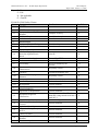
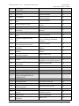
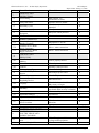
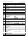
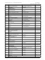
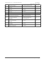
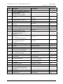
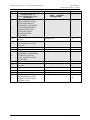
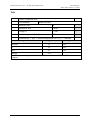
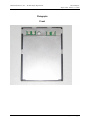
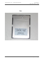
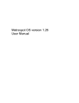
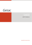
CE Safety Compliance Report
For
Summit Data Communications
Model
SDC-CF10AG
In accordance with
EN 60950-1:2001
Safety of information technology equipment,
CLIENT: Summit Data Communications
526 South Market
Suite 805
Akron, OH
USA
REPORT DATE: January 17, 2008
COMPLIANCE ENGINEER: ___________________________
Roberto Pasos
TECHNICAL REVIEWER: ___________________________
Tou Vang
PRODUCT SAFETY MANAGER: ___________________________
Dave Jeffords
This report shall not be reproduced except in its entirety, without the written approval of Elliott
Laboratories, Inc.
File: R70540
Page 1 of 21 pages
Elliott Laboratories, Inc. -- Product Safety Department
CE Test Report
Report Date: January 17, 2008
Table of Contents
TABLE OF CONTENTS ......................................................................................................................................2
MANUFACTURER'S GENERAL INFORMATION: ..........................................................................................3
REPORT OBJECTIVE: ...........................................................................................................................................3
PRODUCT FUNCTION:..........................................................................................................................................3
EU DECLARATION OF CONFORMITY: .....................................................................................................4
MANUFACTURER'S DOCUMENTATION: .................................................................................................4
GENERIC CONSTRUCTION CRITERIA: ....................................................................................................4
PRODUCT DESCRIPTION ................................................................................................................................5
TESTS.......................................................................................................................................................................18
EQUIPMENT LIST ................................................................................................................................................19
PHOTOGRAPHS ....................................................................................................................................................20
File: R70540
Page 2 of 21 pages
Elliott Laboratories, Inc. -- Product Safety Department
CE Test Report
Report Date: January 17, 2008
Manufacturer's General Information:
Declaration Holder/Manufacturer: Summit Data Communications
526 South Market
Suite 805
Akron, OH
USA
Phone: (330) 289-7959
Fax: (330) 434-7931
Manufacturer's Representative: Ron Seide
Report Objective:
The Summit Data Communications model SDC-DF10AG has been evaluated in accordance with
the following standard: EN 60950-1:2001 Safety of information technology equipment,
including electrical business equipment".
The Summit Data Communications model SDC-DF10AG has been found to be compliant with the
above standard for safety construction of the product and for the required safety performance
testing. The clauses referenced in this report are applicable to the subject product. Comments
pertaining to the clauses are for clarification or support of compliance to the clause. If clauses are
not referenced, they are either non-applicable or narrative in nature.
Product Function:
The Summit Data Communications model SDC-DF10AG is a Wi-Fi radio transmitter that is
designed to transmit data signals. The EUT would typically be connected to a portable data device.
Therefore, the EUT was tested within a LXE Hand Held Computer/Scanner and treated as hand
held. The EUT is powered by 3.3Vdc coming from the data device.
File: R70540
Page 3 of 21 pages
Elliott Laboratories, Inc. -- Product Safety Department
CE Test Report
Report Date: January 17, 2008
EU Declaration of Conformity:
The above Standard has been identified as the harmonized standard that needs to be met before
declaring conformity with the Low Voltage (73/23/EEC) Directive. This Report per this Standard
can serve as part of the documentation to be placed in the product Technical File as required by the
Directive. The existence of a Technical File is required to support the EU Declaration of
Conformity for this product. In addition to the Technical File, the Directive requires a "Declaration
of Conformity" to the applicable standards (and/or Directives) and the affixing of the CE Marking
to the product or its packaging.
Manufacturer's Documentation:
The manufacturer must keep the following documents on file and readily available if requested by
the competent authorities.
1.
Declaration of Conformity.
2.
Copy of this Report.
3.
Material such as design specifications, schematics, drawings, BOM's, operators' guides, and
other supporting documentation in the Technical File. This file must be kept for 10 years after the
last unit is produced and marketed in order to meet European Union requirements in effect at the
publishing date of this report.
Generic Construction Criteria:
Interconnecting Cables: All interconnecting cables and cable assemblies used for external
interconnection between parts of equipment or between components of a system are UL, CSA,
Harmonized (HAR) marked VW-1 or FT-1, or equivalent rated for the temperature, voltage, and
current in which it is exposed.
Printed Circuit Boards: All printed circuit boards, including flexible circuit boards, have a
minimum flame rating of 94V-1 and a temperature rating of at least 105 °C.
Tubing/Sleeving: All tubing/sleeving used for compliance with the standards is UL, CSA, HAR or
equivalent, rated for the temperature, voltage and current in which it is exposed.
Plastics: All internal plastics (excluding small electrical components, i.e., capacitors, chips & etc.)
have a minimum flammability rating of V-2.
Dimensions: All dimensions are approximate unless otherwise specified.
Miscellaneous Components: Components not specifically described in the product description
portion of this report are not deemed critical to safety. However, they should comply with the
Generic Construction Criteria.
Plastics: All internal plastics (excluding small electrical components, i.e., capacitors, chips & etc.)
have a minimum flammability rating of 94-HB
File: R70540
Page 4 of 21 pages
Elliott Laboratories, Inc. -- Product Safety Department
CE Test Report
Report Date: January 17, 2008
Product Description
General Product Information:
Product Type:
WiFi Compact Flash Card
Models:
SDC-SD10AG
Electrical Ratings:
3.3Vdc .5A Max.
Insulation Class:
Class III
Connection to Supply: Compact Flash slot
Components:
Components that bear approval by a certification agency are denoted with the following
abbreviations:
(VDE) - Verband Deutscher Electrotechniker
(TÜV Rh.) -Technische Uberwachungs-Verein - Rheinland
(TÜV PS)-Technische Uberwachungs-Verein - Product Service
(CSA) - Canadian Standards Association
(UL) - Underwriters Laboratories
(HAR) - Harmonized, approved component to a European Harmonized standard
**
Indicates the component has a Certificate or License to an EN or IEC standard.
@@
Indicates compliance to a standard with equivalent requirements of EN 60950-1
The term "or equiv." is used in the report to denote components for which an equivalent
manufacturer or part number may be used without affecting compliance with the applicable safety
standards. Components not specified with an "or equiv." should be evaluated for continued
compliance with the standards.
Enclosure Description and List of Critical Components
1.
Component
Enclosure
Manufacturer, Type, Rating
Various, V-1
Tested By
UL
2.
Printed wiring board
Various
Min V-1, 105°C
UL
File: R70540
Page 5 of 21 pages
Elliott Laboratories, Inc. -- Product Safety Department
CE Test Report
Report Date: January 17, 2008
Key - P – Pass
F – Fail
N – Not applicable
G – General
EN 60950-1:2001 Safety Clauses
Clause
1
1.1
1.2.5
1.2.6
Description
GENERAL
SCOPE
Equipment Covered By This
Standard
Additional Requirements
Exclusions
DEFINITIONS
Equipment Electrical Ratings
Operating Conditions
Equipment Mobility
Classes of Equipment Protection Against Electric
Shock
Connection to the Supply
Enclosures
1.2.7
Accessibility
1.1.1
1.1.2
1.1.3
1.2
1.2.1
1.2.2
1.2.3
1.2.4
1.2.8
1.2.9
1.2.10
1.2.11
1.2.12
1.2.13
1.3
1.3.1
1.3.2
1.3.3
1.3.4
1.3.5
1.3.6
1.3.7
1.3.8
1.3.9
Circuits and Circuit
Characteristics
Insulation
Clearance and Creepage
Distances
Components
Flammability
Miscellaneous
GENERAL
REQUIREMENTS
Application of Requirements
Equipment Design and
Construction
Supply Voltage
Constructions not Specifically
Covered
Equivalent Materials
Orientation During Transport
and Use
Choice of Criteria
Examples Mentioned in the
Standard
Conductive Liquids
File: R70540
Test Results
Pass/Fail
-
Computer accessory
P
No additional requirements
No exclusions
Consider adequate
Normal
Hand-held
N
N
P
P
P
Class III
P
Powered by SELV source
N
P
Plastic 94V-1
No access intended by the
operator
N
No primary circuits
N
Functional insulations used
P
No primary circuits
N
Definitions
Various classes defined
General statement
P
P
P
-
General statements
The equipment is a Class III with no
hazardous voltage and the enclosure is
rated 94V-1
Electrical rating is 3.3Vdc .5A
P
General statements
N
General statements
N
N
General statements
General statements
General statements
General statements
P
P
N
N
N
Page 6 of 21 pages
Elliott Laboratories, Inc. -- Product Safety Department
1.4.1
1.4.2
GENERAL CONDITIONS
FOR TESTS
Application of Tests
Type Tests
1.4.3
Test Samples
1.4.4
Operating Parameters for
Tests
1.4.5
Supply Voltage for Tests
1.4.6
Supply Frequency for Tests
Electrical Measuring
Instruments
Normal Operating Voltages
Measurement of Voltage to
Earth
1.4
1.4.7
1.4.8
1.4.9
1.4.10
Loading Configuration of the
EUT
1.5
Power From a
Telecommunication Network
Temperature Measurement
Conditions
Temperature Measurement
Methods
Simulated Faults and
Abnormal Conditions
COMPONENTS
1.5.1
General
1.4.11
1.4.12
1.4.13
1.4.14
1.5.2
1.5.3
1.5.4
1.5.5
1.5.6
1.5.7
1.5.7.1
1.5.7.2
1.5.7.3
1.5.8
1.6
1.6.1
1.6.2
1.6.3
Evaluation and Testing of
Components
Thermal Controls
Transformers
Interconnecting Cables
Capacitors in Primary Circuits
DOUBLE OR REINFORCED
INSULATION BRIDGED BY
COMPONENTS
Bridging Capacitors
Bridging Resistors
Accessible Parts
Components in Equipment for
IT Power Systems
POWER INTERFACE
AC Power Distribution
Systems
Input Current
Voltage Limit of Hand-Held
Equipment
File: R70540
CE Test Report
Report Date: January 17, 2008
General statements
General statements
Samples are representative of
the actual product
N
P
General Statement
N
P
Tests were preformed at
3.1Vdc
DC
All test equipment used is calibrated
annually
General statements
P
N
P
N
General statements
N
Tested under normal operations. Load
was an LXE Rugged Handheld
Computer
P
General statements
N
Room Temperature as
ambient
J-Type Thermocouple
method
N
P
Output short-circuit
P
-
All applicable components,
equipments were agencies approved
P
General requirements
N
No such controls
No mains transformers
No interconnection cables
No primary circuit
N
N
N
N
-
No capacitors of this type
No resistors of this type
No such parts used
N
N
N
Not for IT Power Systems
N
-
Not an AC power
distribution system
SELV consideration
Below 250V
N
P
P
Page 7 of 21 pages
Elliott Laboratories, Inc. -- Product Safety Department
1.6.4
1.7
Neutral Conductor
MARKINGS AND
INSTRUCTIONS
1.7.1
Power Rating
1.7.2
Safety Instructions
1.7.3
Short Duty Cycles
1.7.4
Supply Voltage Adjustment
Power Outlets of the
Equipment
Fuse Identification
WIRING TERMINALS
Protective Earthing and
Bonding Terminals
Terminals for a.c. Mains
Supply Conductors
Terminals for d.c. Mains
Supply Conductors
CONTROLS AND
INDICATORS
Identification, Location, and
Marking
Colors
Symbols
Markings Using Figures
Isolation of Multiple Power
Sources
IT Power Systems
Thermostats and Other
Regulating Devices
1.7.5
1.7.6
1.7.7
1.7.7.1
1.7.7.2
1.7.7.3
1.7.8
1.7.8.1
1.7.8.2
1.7.8.3
1.7.8.4
1.7.9
1.7.10
1.7.11
CE Test Report
Report Date: January 17, 2008
General Statements
N
-
Not required. No
connections to mains.
Stated in the user manual
Continuous operation
intended
No adjustment
N
No power outlets provided
N
None used
N
-
Equipment is Class III
N
No a.c. mains connections
N
No d.c. mains connections
N
N
P
N
Unit is properly labeled.
P
No such parts
Standby symbol provided
No such markings
N
P
N
No multiple power source
N
Not for IT systems
N
No such devices
N
1.7.12
Language
1.7.13
Durability
1.7.14
1.7.15
Removable Parts
Replaceable Batteries
Intended to be translated for
the country of import
All markings on the equipment are
evaluated under its safety evaluation.
No removable parts
No batteries
1.7.16
Operator Access With a Tool
Equipment for Restricted
Access Locations
No access intended
Not for restricted access
locations
Description
PROTECTION FROM HAZARDS
PROTECTION FROM
ELECTRIC SHOCK AND
ENERGY HAZARDS
Protection in operator access
areas
Access to Energized Parts
Test Results
1.7.17
Clause
2
2.1
2.1.1
2.1.1.1
File: R70540
P
P
N
N
N
N
Pass / Fail
-
Class III equipment. No hazardous
voltage within equipment.
See above
N
N
Page 8 of 21 pages
Elliott Laboratories, Inc. -- Product Safety Department
2.1.1.2
2.1.1.3
Battery Compartments
Access to ELV Wiring
2.1.1.4
Access to Hazardous Voltage
Circuit Wiring
2.1.1.5
2.1.1.6
Energy Hazards
Manual Controls
2.1.1.7
Discharge of Capacitors in the
Primary Circuit
2.1.2
2.1.3
2.2
2.2.1
2.2.2
2.2.3
2.2.3.1
2.2.3.2
2.2.3.3
2.2.4
2.3
2.3.1
2.3.2
2.3.3
2.3.4
2.3.5
2.4
2.4.1
2.4.2
2.4.3
2.5
2.6
2.6.1
2.6.2
Protection in Service Access
Areas
Protection in Restricted
Access Areas
SELV CIRCUITS
General requirements
Voltages under normal
conditions
CE Test Report
Report Date: January 17, 2008
No TNV
No ELV wiring
Class III equipment. No
hazardous voltage within
equipment.
No energy hazardous
No such conductive controls
Equipment does not connect
to an a.c. or d.c. mains
supply
No serviceable parts inside
intended.
N
N
No such location
N
General requirements
P
3.3Vdc
P
VOLTAGES UNDER
FAULT CONDITIONS
Separation by double or Reinforced
Insulation (Method 1)
Separation by Earthed Screen
(Method 2)
Protection by Earthing of
SELV Circuit (Method 3)
Connection of SELV Circuits
to Other Circuits
TNV CIRCUITS
Limits
Separation From Other Circuits and
From Accessible Parts
Separation From Hazardous
Voltages
Connection of TNV to Other
Circuits
Test for Operating Voltages
Generated Externally
LIMITED CURRENT
CIRCUITS
General requirements
Limit Values
Connection of Limited Current
Circuits to Other Circuits
LIMITED POWER
SOURCES
PROVISIONS FOR
EARTHING AND BONDING
Protective Earthing
Functional Earthing
File: R70540
N
N
N
P
N
No reinforced insulation within
equipment
N
Class III Equipment
N
Class III Equipment
N
No connections
N
No TNV circuit present
N
No TNV circuit present.
N
No TNV circuit present.
N
No TNV circuit present.
N
No TNV circuit present.
N
-
No limited current circuits present
No limited current circuits present
N
N
No limited current circuits present
N
No limited power sources present
N
Equipment is Class III
Equipment is Class III
N
N
Page 9 of 21 pages
Elliott Laboratories, Inc. -- Product Safety Department
2.6.3
2.6.3.1
2.6.3.2
2.6.3.3
2.6.3.4
2.6.4
2.6.4.1
2.6.4.2
2.6.5
2.6.5.1
2.6.5.2
2.6.5.3
2.6.5.4
2.6.5.5
2.6.5.6
2.6.5.7
2.6.5.8
2.7
2.7.1
2.7.2
2.7.3
2.7.4
2.7.5
2.7.6
2.8
2.8.1
CE Test Report
Report Date: January 17, 2008
PROTECTIVE EARTHING
AND PROTECTIVE
BONDING CONDUCTORS
Size of Protective Earthing
Conductors
Size of Protective Bonding
Conductors
Resistance of Earthing
Conductors and Their
Terminations
Color of Insulation
TERMINALS
Protective Earthing and
Bonding Terminals
Separation of the Protective
Earthing Conductor From
Protective Bonding
Conductors
INTEGRITY OF
PROTECTIVE EARTHING
Interconnection of Equipment
Equipment is Class III
N
Components in Protective
Earthing Conductors and
Protective Bonding
Conductors
See above
N
See above
N
See above
N
See above
N
See above
See above
N
N
See above
N
Disconnection of Protective
Earth
Parts That Can be Removed
by an Operator
Parts Removed During
Servicing
Corrosion Resistance
Screws For Protective Boding
Reliance on
Telecommunication Network
OVERCURRENT AND
EARTH FAULT
PROTECTION IN PRIMARY
CIRCUITS
Basic Requirements
Faults Not Covered in SubClause 5.3
Short-Circuit Backup
Protection
Number and Location of
Protective Devices
Protection by Several Devices
Warning to Service Personnel
SAFETY INTERLOCKS
General Principals
File: R70540
Equipment is Class III
N
See above
N
See above
N
See above
N
-
Equipment is Class III
N
See above
N
-
No primary circuits
N
See above
N
See above
N
See above
N
See above
See above
N
N
N
No interlocks
Page 10 of 21 pages
Elliott Laboratories, Inc. -- Product Safety Department
2.8.2
2.8.3
2.8.4
2.8.5
2.8.6
2.9.2
2.9.3
Protective Requirements
Inadvertent Reactivation
Fail-Safe Operation
Interlock With Moving Parts
Overriding an Interlock
SWITCHES AND RELAYS
IN INTERLOCK SYSTEMS
Contact Gaps
Overload Test
Endurance Test
Electric Strength Test
Mechanical Actuators
ELECTRICAL INSULATION
Properties of Insulating
Materials
Humidity Conditioning
Requirements For Insulation
2.9.4
Insulation Parameters
2.9.5
2.10.5.2
2.10.5.3
Categories of Insulation
CLEARANCES, CREEPAGE
DISTANCES AND
DISTANCES THROUGH
INSULATION
General
Determination of Working
Voltage
Clearances
General
Clearances in Primary Circuits
Clearance in Secondary
Circuits
Measurement of Transient
Levels
Creepage Distances
Solid Insulation
Minimum Distance Through
Insulation
Thin Sheet Material
Printed Boards
2.10.5.4
Wound Components
2.10.6
2.10.6.1
Coated Printed Boards
General
Sample Preparation and
Preliminary Inspection
Thermal Cycling
2.8.7
2.8.7.1
2.8.7.2
2.8.7.3
2.8.7.4
2.8.8
2.9
2.9.1
2.10
2.10.1
2.10.2
2.10.3
2.10.3.1
2.10.3.2
2.10.3.3
2.10.3.4
2.10.4
2.10.5
2.10.5.1
2.10.6.2
2.10.6.3
File: R70540
CE Test Report
Report Date: January 17, 2008
No interlocks
No interlocks
No interlocks
No interlocks
No interlocks
N
N
N
N
N
-
No interlocks
No interlocks
No interlocks
No interlocks
No interlocks
N
N
N
N
N
-
Evaluated under each safety approved
equipments
See above
See above
See above
See above
N
N
P
P
P
-
Equipment is rated 3.3Vdc
See above
N
N
No primary circuits
See above
See 5.3.4c
N
N
P
No transient voltages
N
See 5.3.4c
P
N
N
See above
None used
See above
No wound components using
basic insulation between
windings
No coated printed boards
See above
See above
N
N
N
N
N
N
Page 11 of 21 pages
Elliott Laboratories, Inc. -- Product Safety Department
2.10.6.4
2.10.6.5
2.10.6.6
2.10.7
2.10.8
2.10.9
Thermal Aging
Electric Strength Test
Abrasion Resistance Test
Enclosed And Sealed Parts
Spacing Filled by Insulating
Compound
Component External
Terminations
2.10.10
Insulation With Varying Dimensions
Clause
Description
WIRING, CONNECTIONS AND
SUPPLY
GENERAL
Current Rating and Over current
Protection
Protection Against Mechanical
Damage
Securing of Internal Wiring
Insulation of Conductors
Beads and Ceramic Insulators
Screws For Electrical Contacts
Pressure
Non-Metallic Materials in
Electrical Connections
Self-Tapping and Spaced
Thread Screws
3
3.1
3.1.1
3.1.2
3.1.3
3.1.4
3.1.5
3.1.6
3.1.7
3.1.8
3.1.9
Termination of Conductors
3.1.10
Sleeving on Wiring
CONNECTION TO A.C.
MAINS SUPPLIES
Means of Connection
Multiple Supply Connections
Permanently Connected
Equipment
Appliance Inlets
Power Supply Cords
Cord Anchorages and Strain
Relief
Protection Against Mechanical
Damage
Cord Guards
Supply Wiring Space
WIRING TERMINALS FOR
CONNECTION OF
EXTERNAL CONDUCTORS
Wiring Terminals
3.2
3.2.1
3.2.2
3.2.3
3.2.4
3.2.5
3.2.6
3.2.7
3.2.8
3.2.9
3.3
3.3.1
File: R70540
CE Test Report
Report Date: January 17, 2008
See above
See above
See above
No enclosure or sealed parts
No spacing filled by
insulation compound
No compound external
terminations
No insulation with varying
dimensions
N
N
N
N
N
N
N
Test Results
Pass/Fail
-
No internal or interconnecting
wires
N
No wireways
N
No internal wires
No internal conductors
No such beads or ceramic insulators
N
N
N
Non used
N
None used
N
No such screws
N
No internal or
interconnecting wires
None used
N
N
-
No a.c. or d.c. mains connections
See above
See above
N
N
See above
See above
See above
N
N
See above
See above
See above
N
N
N
N
N
-
No such terminals
N
Page 12 of 21 pages
Elliott Laboratories, Inc. -- Product Safety Department
3.3.2
3.3.3
3.3.4
3.3.5
3.3.6
3.3.7
3.3.8
3.4
Connection of NonDetachable Power Supply
Cords
Screw Terminals
Conductor Sizes to be
Connected
Wiring Terminal Sizes
Wiring Terminal Design
Grouping of Wiring Terminals
Stranded Wire
DISCONNECTION FROM
THE A.C. MAINS SUPPLY
3.4.1
General Requirement
3.4.2
Disconnect Devices
Permanently Connected
Equipment
Parts Which Remain
Energized
Switches in Flexible Cords
Single-Phase Equipment
Three-Phase Equipment
Switches as Disconnect
Devices
Plugs as Disconnect Devices
Interconnected Equipment
Multiple Power Sources
INTERCONNECTION OF
EQUIPMENT
3.4.3
3.4.4
3.4.5
3.4.6
3.4.7
3.4.8
3.4.9
3.4.10
3.4.11
3.5
3.5.1
3.5.2
3.5.3
General Requirements
Types of Interconnection
Circuits
ELV Circuits as
Interconnection Circuits
Clause
4
4.1
4.2
4.2.1
Description
PHYSICAL REQUIREMENTS
STABILITY
MECHANICAL STRENGTH
General
4.2.2
Steady Force Test, 10 N
4.2.3
4.2.4
4.2.5
4.2.6
4.2.7
4.2.8
Steady Force Test, 30 N
Steady Force Test, 250 N
Impact Test
Drop Test
Stress Relief
Cathode Ray Tubes
File: R70540
CE Test Report
Report Date: January 17, 2008
Non detachable power
supply cords not used
N
No such terminals
N
None used
N
No wiring terminals used
See above
See above
See above
N
N
N
N
-
Equipment does not connect
to mains supply
See above
N
See above
N
See above
N
See above
See above
See above
N
N
N
See above
N
See above
See above
See above
N
N
N
N
Does not connect to other
equipment
N
See above
N
See above
N
Test Results
General requirements
No hazardous voltage within
equipment
No covers or door
See above
See above
See above
See above
No such tube
Pass / Fail
N
N
N
N
N
N
N
N
Page 13 of 21 pages
Elliott Laboratories, Inc. -- Product Safety Department
4.2.9
4.2.10
4.3
High Pressure Lamps
Wall or Ceiling Mounted
Equipment
DESIGN AND
CONSTRUCTION
4.3.1
Edges and Corners
4.3.2
4.3.3
4.3.4
4.3.8
Handles and Manual Controls
Adjustable Controls
Securing of Parts
Connection of Plug and
Sockets
Direct Plug-In Equipment
Heating Elements in Earthed
Equipment
Batteries
4.3.9
Oil And Grease
4.3.5
4.3.6
4.3.7
4.3.10
4.3.11
4.3.12
4.3.13
4.4
4.4.1
4.4.2
4.4.3
4.4.4
4.5
Dust, Powders, Liquids and
Gases
Containers For Liquids or
Gases
Flammable Liquids
Radiation
PROTECTION AGAINST
HAZARDOUS MOVING
PARTS
General
Protection in Operator Access
Areas
Protection in Restricted
Access Locations
Protection in Service Access
Areas
THERMAL
REQUIREMENTS
4.5.1
Temperature Rises
4.5.2
Resistance to Abnormal Heat
OPENINGS IN
ENCLOSURES
4.6
4.6.1
Top and Side Openings
4.6.2
Bottoms of Fire Enclosures
Doors or Covers in Fire
Enclosures
Openings in Transportable
Equipment
Adhesives for Constructional
Purposes
RESISTANCE TO FIRE
4.6.3
4.6.4
4.6.5
4.7
File: R70540
CE Test Report
Report Date: January 17, 2008
No high pressure lamps
Not a wall or ceiling mount
equipment
N
N
-
Smooth edges and corners
provided
No manual control
No adjustable control
Secured as required
No hazard from misconnection of
plugs and sockets
Not direct plug in equipment
P
N
N
P
P
N
No such elements
N
No batteries provided
Not intended to be subjected to oil or
grease
N
Does not produce these
N
No such containers
N
No such liquids
Does not produce radiation
N
N
N
No moving parts
N
See above
N
See above
See above
N
N
-
See appended table below
for details
No Hazardous voltages
P
N
-
No hazardous voltage within
equipment.
See above
N
See above
N
See above
N
See above
N
N
Page 14 of 21 pages
Elliott Laboratories, Inc. -- Product Safety Department
4.7.3
4.7.3.1
Reducing the Risk of Ignition
and Spread of Flame
Conditions for a Fire
Enclosure
Parts Requiring a Fire
Enclosure
Parts Not Requiring a Fire
Enclosure
Materials
General
4.7.3.2
Materials for Fire Enclosures
4.7.1
4.7.2
4.7.2.1
4.7.2.2
4.7.3.3
4.7.3.4
4.7.3.5
4.7.3.6
Materials for Components and
Other Parts Outside Fire
Enclosures
Materials for Components and
Other Parts Inside Fire
Enclosure
Materials for Air Filter
Assemblies
Materials Used in HighVoltage Components
File: R70540
CE Test Report
Report Date: January 17, 2008
V-0 plastic enclosure is used
P
P
See above
N
See above
N
General requirements
94V-1 plastic enclosure is
used
N
P
Evaluated under individual
equipment approvals
N
See above
N
See above
N
See above
N
Page 15 of 21 pages
Elliott Laboratories, Inc. -- Product Safety Department
Clause
5
5.1
Description
ELECTRICAL REQUIREMENTS and
SIMULATED ABNORMAL CONDITIONS
TOUCH CURRENT AND
PROTECTIVE
CONDUCTOR CURRENT
5.1.1
General
5.1.2
5.1.3
5.3.2
5.3.3
Equipment Under Test (EUT)
Test Circuit
Application of Measuring
Instrument
Test Procedure
Test Measurements
Equipment With Touch
Current Exceeding 3.5 ma
Touch Currents to and From
Telecommunications
Networks
Limitation of the Touch
Current To a
Telecommunication Network
Summation of Touch Current
From Telecommunication
Networks
ELECTRIC STRENGTH
General
Test Procedure
ABNORMAL OPERATING
AND FAULT CONDITIONS
Protection Against Overload
and Abnormal Operation
Motors
Transformers
5.3.4
Functional Insulation
5.1.4
5.1.5
5.1.6
5.1.7
5.1.8
5.1.8.1
5.1.8.2
5.2
5.2.1
5.2.2
5.3
5.3.1
5.3.5
5.3.6
5.3.7
5.3.8
5.3.8.1
5.3.8.2
Electromechanical
Components
Simulation of Faults
Unattended Equipment
Compliance Criteria for
Abnormal Operating and Fault
Conditions
During the Tests
After the Tests
File: R70540
CE Test Report
Report Date: January 17, 2008
Test Results
Pass / Fail
-
d.c powered, test not
required
See above
See above
N
N
See above
N
See above
See above
N
N
See above
N
N
-
See above
N
See above
N
General statement
General statement
P
P
-
Test not required
N
No motors
No transformer
Meets the creepage and
clearance requirements
N
N
P
No such components
N
General test scenarios
No such thermal controls
N
N
-
Not required
Not required
N
N
Page 16 of 21 pages
Elliott Laboratories, Inc. -- Product Safety Department
Clause
6
6.1
6.1.1
6.1.2
6.1.2.1
6.1.2.2
6.2
6.2.1
6.2.2
6.2.2.1
6.2.2.2
6.2.2.3
6.3
Description
CONNECTION TO
TELECOMMUNICATION
NETWORKS
PROTECTION OF
TELECOMMUNICATION
NETWORKS SERVICE
PERSONNEL, AND USERS
OF OTHER EQUIPMENT
CONNECTED TO THE
NETWORK, FROM
HAZARDS IN THE
EQUIPMENT
Protection from hazardous
voltages
Separation of the
telecommunication network
from earth
Requirements
Exclusions
PROTECTION OF
EQUIPMENT USERS FROM
OVERVOLTAGES ON
TELECOMMUNICATION
NETWORKS
Separation requirements
Electric strength test
procedure
Impulse test
Steady-state test
Compliance criteria
PROTECTION OF THE
TELECOMMUNICATION
WIRING SYSTEM FROM
OVERHEATING
File: R70540
CE Test Report
Report Date: January 17, 2008
Test Results
None
provided,
Not applicable
Pass / Fail
-
-
No applicable
N
-
No applicable
No applicable
N
N
-
No applicable
N
-
No applicable
No applicable
No applicable
No applicable
N
N
N
N
Page 17 of 21 pages
Elliott Laboratories, Inc. -- Product Safety Department
CE Test Report
Report Date: January 17, 2008
Tests
TABLE: temperature tests
P
Test conditions
Normal Full Load
Frequency (Hz)
:
dc
⎯
Duration (h, min)
:
5 hours
⎯
Voltage (V)
:
3.1Vdc
⎯
Ambient temperature Ta (°C)
:
17.8
⎯
Measurements: 1 - part; 2 - measured temperature (Tm (°C)); 3 – comments
1
2
3
Enclosure
46
Pass
U1
44
Pass
PWB
43
Pass
17.8
Ambient
Note: Temperature testing was done with the EUT connected to an LXE Handheld
Computer.
File: R70540
Page 18 of 21 pages
Elliott Laboratories, Inc. -- Product Safety Department
CE Test Report
Report Date: January 17, 2008
Equipment List
Heating Test
Engineer: Roberto Pasos
Manufacturer
Omega Engineering
Fluke
File: R70540
Description
Temp Reader
Multi Meter
Model #
73
Asset #
00818
00077
Cal Due
30-Mar-08
30-Mar-08
Page 19 of 21 pages
Elliott Laboratories, Inc. -- Product Safety Department
CE Test Report
Report Date: January 17, 2008
Photographs
Front
File: R70540
Page 20 of 21 pages
Elliott Laboratories, Inc. -- Product Safety Department
CE Test Report
Report Date: January 17, 2008
Rear
File: R70540
Page 21 of 21 pages