1
PROGRAMMABLE
CONTROLLER
User's Manual
y,;T
F
[?-'$:
External charactor display unit
type AGFD
MlTSUBlSHl
ELECTRIC
REVISIONS
%The manual number is given on the bottom left of the back cover.
Print Date
'Manual Number
Sep., 1987
.IB (NA) 66139-A
First ed~tion
Apr., 1989
IB (NA) 661394
Correction
Page 2-1, 3-1
Revision
I
"Instruct~onsfor Strategic Materials" added
INTRODUCTION
Thank you for choosing the Mltsubishi MELSEC-A Series of General Purpose Programmable
Controllers. Please read thls manual carefully so that the equipment is used to its optimum.
A copy of thls manual should be forwarded to the end User.
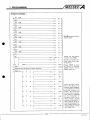
7.1
7.2
7.3
7.4
.......................................................................................7-1
Programming Application Examples 1 (For A l . A2. A3CPU) ....................................... 7-6
programming Application Example 2 (For AOJ2CpU) ............................................. 7-22
Display of Numerical Variables ........................................................................... 7-24
Basic Display Programs
IB (NA) 66139-A
1. GENERAL DEscRlPTsoN
/MELSEC
This User's Manual describes the specifications, handling, programming procedures, etc. of the AGFD external display unit
(hereinafter referred to as "AGFD") for use with the MELSEC-A
series of Programmable .Controllers.
The examples used in this manual are based on the MELSEC-A
, Series PCs. Other sybtems may be compatible providing the AGFD
specifications are met.
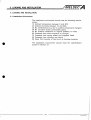
1.1 How to Use This Manual
This manual is divided as follows:
Chapter 2 System Configuration
Describes the system configurations required for using
the AGFD.
Chapter 3 Specifications
Performance, electrical and power supply specifications.
Chapter 4 Handling
Nomenclature and handling instructions.
Chapter 5 Loading and Installation
Installation and wiring instructions
Chapter 6 Display control signals and timing.
Explains the control signals required from the output
unit t o the AGFD.
Chapter 7 Programming
Explains the special instructions used t o control the
AGFD and gives program examples that do not use the
special AGFD control instructions.
Chapter 8 Test
Pre-test and test procedures
Chapter 9 Troubleshooting
Chapter 10 Maintenance and Inspection
1. GENERAL DEscRlPTloN
-~-
/MELSEC
Appendices
External dimensions, character set and codes. Notes
on connection of the A6FD with general types of
output devices.
I
I
The following manuals may also.be required
A1 (E), A2(E); A3(E)CPU User's Manual
A1 (E), A2(E), A3(E)CPU Programming Manual
AOJ2CPU User's Manual (CPU edition)
AOJ2CPU Programming Manual
A6GPP Operating Manual ( A series) .
Other A series manuals
?
/MELSEC
2. SYSTEM CoNFlGuRATloN
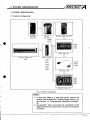
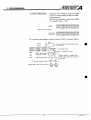
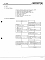
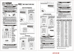
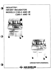
2 SYSTEM CONFIGURATION
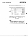
2.1 System Configuration
AOJ2CPU
(P23lR23)
.
,
I10 unit '
AOJ2-E24T-
B u ~ l d ~ nblock
g
type CPU
A38B
A35B
A32B
.
External dlsplay unlt
A6FD
Output module
AY40
AY41
AY42
AY50
AY51
AY80
AY81
.
.,
Extension cable
'
a
A68B
A65B
A58B
A55B
Extension base u n ~ t
I
Fig. 2.1 System Configuration
POINT
I
1. If using the A6FD i n a data link system remote I10
station, refer t o Section 6.1"Display Output Timing" (1)
and Section 7.2 "Programming Application Example"
(4).
2. An extension base unit cannot be connected t o the
A32B main base unit which does not have an extension
connector.
/MELSEC
2. SYSTEM CoNFlGuRATloN
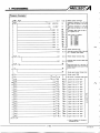
2.2 Equipment
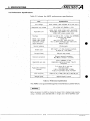
Table 2.1 l ~ s t sthe A serles output and I10 units t o w h i c h t h e AGFD
can b e connected. (available at t i m e o f printing):
Name
Type
Output
unit
(for A l ,
2, 3CPU)
AY42
Name
110 unit
Output Specifications
16-po~nt,12124V DC trans~storoutput unlt
( S ~ n koutput)
(for 0 1 ~ )
32-po~nt, 12124V DC trans~storoutput unlt
(for 0 . 1 ~ )
( S ~ n koutput)
64-po~nt,12124V DC trans~storoutput unlt
(for 0.1A)
( S ~ n koutput)
16-po~nt,12124V DC trans~storoutput unlt
(for 0 5A)
( S ~ n koutput)
32-polnt, 12124V DC translstor output unlt
(for 0 5A)
( S ~ n koutput)
16-po~nt,12124V DC translstor output unlt
(for 0.5A w ~ t hfuse)
(Source output)
32-polnt, 12124V DC trans~storoutput unit
(for 0 5A wlth fuse)
(Source output)
Output Specifications
Type
. A0J2-E24T
24
AOJ2-E28DT 12 polnts
AOJ2-E56DT 24 p o ~ n t s
(for
12124~DC translstor output unit
(for 0.5A) ( S ~ n koutput)
Table 2.1 Unit List
POINT
)
.
'
1. Relay output units should not be used due to the duty
cycles imposed by the special AGFD control instructions
2. Any I10 slot may be used for the control of the AGFD.
.
3. SPECIFICATIONS
3.1 General Specifications
Table 3.1 shows general specifications of the AGFD.
By n o s e s~mulator1500Vpp nolse voltage,
IPS
n o s e w ~ d t hand 25 t o 60Hz nolse frequency
N o ~ s ed u r a b ~ l ~ t y
D~electr~c
withstand
1500V AC for 1 rnlnute across batch of AC external terrn~nals
and ground
500V AC for' 1 rnlnute across DC external terrn~nalsand ground
lnsulat~on
resistance
n
tester across
5MR or larger by 500V DC ~ n s u l a t ~ oresistance
AC external terrn~nalsand ground
Ground~ng
Class 3 ground~ng,ground~ngIS not necessary of the operat~onof the un~t
Operat~ng
arnb~ence
Free of
corrosive
Cool~ngmethod
gases Dust should be m ~ n ~ m a l
Self-cool~ng
7
Table 3.1 General Specifications
I
REMARKS
I
*
One octave marked
ind~catesa change from the ~ n ~ tfrequency
~al
to double or
half frequency. For example, any of the changes from 10Hz to 20Hz, from 20Hz t o
40Hz, from 40Hz t o 20Hz, and 20Hz t o 10Hz are referred t o as one octave.
"'JIS Japanese Industrial Standard.
/MELSEC
3. SPEclFlcATloNs
..- .
- .
3.2 Performance Specifications
Table 3.2 shows the A6FD performance specifications.
Item
Specifications
Llne voltage
Input voltage. 100V AC/200V AC (0 12A max )
Applicable llne voltage
85 to 264V AC (50160Hz
8 data llnes (DO to D7), 1 strobe llne (STROBE),
1 common l ~ n e(COM)
12124V DC
4mA (12V DC), 10rnA (24V DC)
10 2 to 26.4V DC(R1pple ratlo wlthln 5%)
Approx. 2.4K R
Interface
Rated Input voltage
Rated. Input current
Appl~cable.voltage
lnput resistance ,
(
lnternal lsolat~on
Control~Gted
[
Photocoupler
1
LED (red) 5 x 7 dots, dynarnlc method,
16 dlglts ~n 1 line ASCII
I
a
Dlsplay t i p e
I
5%)
AY40, AY41, AY42, AY50, AY51, AOJ2-E24T,
AOJ2-E28DT, AOJ2-E56DT s ~ n koutput u n ~ t s
AY80, AY81 source output unlts
Appllcable u n ~ t
I
k
,
-
Manual reset s w ~ t c h
External connection
20-polnt termlnal connector
M3 (Metrlc thread) x 6 screws
Applicable wlre slze
2mm2 (14AWG) or less
( ~ p p ! l c a b l etlghtenlng torque. 7kg cm
. .
(0.5llb.ft))
Applicable solderless
termlnal
Slze mm(1nch)
To f ~ 3mrn
t
(0 12 Inch) dla.
termlnal screws
1 25-3, 1.25-YS3A, 2S3, 2-YS3A,
V1 25-3, V1.25-YS3A, V2-S3, V2-YS3A
145(5.71) (D) x 290(11 42) (W) x 60(2 36) (H)
Table 3.2 ~ e i o r m a n c eSpecifications
.
*
The AGFD is not guaranteed ageinst.instantaneous power failure.
I
REMARKS
I
Before shipment, the AGFD IS checked to ensure that ~t d~splaysdata properly,
uslng a shlelded cable 200m(656 18ft) In length and 0 18mm2(24AWG)CSA
/MELSEC
3. SPEciFlcATloNs
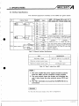
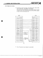
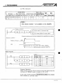
3.3 Interface Specifications
The external equipment interface of the AGFD are given below.
If0
Terminal
Number
Internal Circuit
Signal
AGFD
PC Output (I/O in slot "n")
Sink output unit
Source output unit
+
I
+
+
+
+
+
+
DO
DO
Yn
0
Dl
Yn 4- 1
0 2 .- Yn
2
3
D3 +- Yn
D4 .- Yn
4
D5 .- Yn 4- 5
Yn
6
D6
7
D7 +- Yn
Yn 4- 8
STROBE
Cons~stsof 8 outputs for data s~gnalsYn+O
to Yn4-7 (DO to D7), 1 output for strobe
(Strobe signal) s~gnalYn+8 (STROBE), and COM (TB11).
NC
COM
Connect
Connect
(common)
12124~DC. ( f )
12124V DC. (OV)
NC
The reset s w ~ t c hclears the A6FD d~splay
and outputs a reset s ~ g n afrom
l
TB13 and
RESET2
TB14 to the f ~ e l d TB13
.
and TB14 are relay
contact outputs
NC
Refer to Table 3.4
NC
+
-
D1
D2
D3
D4
D5
D6
D7
Input
7
TB1l
Output Reset swltch
+
-
+
-
+
-
I
Table 3.3 External Interface Specifications
Item
Specifications
Appl~cablevoltage
100V AC, 200V AC, 5 to 48V DC
M ~ n ~ r n ucontact
m
current value
Im A
M a x ~ m u mcontact current value
2A (Res~storload)
Table 3.4 "Reset" output from A6FD
POINT
1
1. The same 12/24V DC power supply should be used for
both the A6FD and the transistor output module.
2. The reset switch clears the display and initializes the
unit. It also closes the relay contacts across TB13 and
TB14.
3. The "NC" terminals are unused by the A6FD (NC for no
connection)
I
REMARKS
I
For the s ~ n kand source output unlts, refer to Append~x3
/MELSEC
3. SPEclFlcATloNs
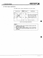
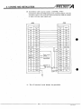
3.4 Power Supply Specifications
The AGFD power supply specifications are given below.
Internal Circuit
Terminal
Number
Signal
TB18
100,
200V AC
100,
2OOV AC
LG
Specifications
Any supply of between 85 and
264V AC may be appl~ed to
terrn~nalsTB18 and TB19.
Input current 0 12A (max.)
Frequency. 50160Hz f 5%)
lnternal voltage: 5V DC 2A
Power filter ground
Table 3.5 Power Supply Specifications
I
POINT
.
(
1. A 200msec delay occurs between power-up and the
A6FD becoming active.
2. Half the supply voltage appears at the LG terminal
(TB20). Do not touch this terminal if the unit is not
grounded.
/MELSEC
4. HANDLING .
4. HANDLING
4.1 Handling Instructions
.
Handle the A6FD carefully as described below:
(1) Do not subject the unit t o impact loads.
(2) Guard against the e n t r i - o f conductive debris into the unit. If
any should enter, switch off the power and remove it.
(3) Do not. touch
the printed circuit board.
.
.
(4) Tighten screws t o the torques given below: .
,
Screw
Torque Range kg cm (Ib ft)
Term~nalblock screws (M3 m e t r ~ cthread)
8 (0 58) to 14 (1.01)
Terrn~nalblock f ~ x ~ nscrews
g
(M4 ketrlc thread)
Unit rnount~ngscrews (M4 rnetr~cthread)
-
8 (0.58)'to 14 (1.01)
5 (0.36) to 8 (0 58)
/MELSEC
4. HANDLING
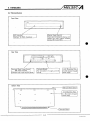
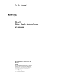
4.2 Nomenclature
F\ront View
\
ACFD
(
LED lnd~cator
D~splays16 ASCII characters.
"
Manual Reset Swttch
7
Rear View
of supply and I10
Bottom View
-
I
Clears and ~ n ~ t ~ a l ithe
z e sd~splayand
closes the relay output contacts
across TB13 and TB14.
5. LOADING AND INSTALLATION
/MELSEC
5. LOADING AND INSTALLATION
5.1 Installation Environment
The installation environment should meet the following requirements:
(1) Ambient temperature between 0 and 55°C.
(2) Ambient humidity between 10 and 90%.
(3) No condensation (e.g. due t o sudden temperature changes)
(4) No corrosive and/or combustible gases.
(5) No airborne conductive or organic powders or mists.
(6)Protected from direct exposure t o sunlight.
(7) Protected from strong power and magnetic fields.
(8) Protected from vibration and shock.
(9) Away from, sources of heat such as heating elements.
The installation environment should meet the specifications
quoted in Section 3.1.
5. LOADING AND INSTALLATION
/MELSEC
5.2 Mounting
5.2.1 General precautions
When installing the A6FD in a panel etc. note the follow~ng:
(1) Install the unit in a well-ventilated place with the operating
ambient temperature less than 55°C.
(2) Avoid installing the unit over large sources of heat (such as a
large-capacity resistor, transformer, or heater).
(3) Do not install the unit near sources of vibration or impact loads
such as large magnetic contactors and no-fuse breakers.
(4) Ensure any "L" brackets used do not obstruct the air flow for
ventilation.
(5) When installing the A6FD on a flat surface, ensure that there is
sufficient clearance for the connection of solderless terminals
to the terminal block.
(6) The mountlng holes In the rear of the face plate are tapped for
M 4 (Metric thread) screws. Recommended screw length is
5.6mm (0.22inch) plus the panel wall thickness.
(7) The mounting holes in the rear of the face plate are tapped for
M 4 (Metric thread) screws. Recommended screw length is
mounting surface thickness plus 5mm (0.20inch).
/MELSE
5. LOADING AND INSTALLATION
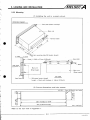
5.2.2 Mounting
(1) Installing the unit in a panel cut-out.
Schemat~cD~agram
Face plate (plast~cm o l d ~ n g )
Terminal block
n ~ mountlng
t
hole M 4 (metric thread)
/Face
0
0
'
plate
&
0
4--
M a ~ nu n ~ t
(Sheet metal)
Top V ~ e w
M4 screw ( m e t r ~ cthread)
+ 5.6mm (0 221nch)
Length = Panel wall th~ckness
(2) Cut-out dimensions and hole centres.
4 (0.16) - 5mm (0.201nch) d ~ a .holes
0
1
--
0
265 5 (10.45)kl .O (0 04)
4
274 (10.79)k0.5 (0.02)
-
4
Refer to the rear view in Appendix 1.
C
U n ~ mm(inch)
t
/MELSEC
5. LOADING AND INSTALLATION
d
i
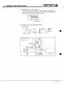
(3) Installation on a flat surface
Rubber pads should be used to provide clearance between the
flat surface and the AGFD for the face plate and solderless
terminal connections, as shown below.
~ u b b e rpads
(4) Installation using extended brackets.
See below. ,
Term~nalblock
Panel
Extended
brackets
Extended :
bracket
A6FD
maln unlt
5-4
IB (NA) 66139-A
/MELSEC
5. LOADING AND INSTALLATION
5.3 Wiring
,
,
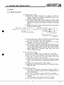
5.3.1 Wiring precautions
(1) Power supply wiring
(a) When line voltage fluctuations are liable t o cause the
supply voltage t o go outside the specified range, use a
constant voltage transformer.
(b) The power supply used should generate minimal noise
between lines and between lines and ground. If the noise
generated is excessive, an isolation transformer should be
used.
(c) Separate PC power supply, I10 equipment and main circuit
wiring as shown below:
Main power
PC power
Ac--LqYlA,"xerF$k
100~
I/O power
2o0~
110 equipment
110 power
I
110
equipment
M a ~ nc~rcuitpower
M a ~ ncircuit
power
(d) Use twisted wire for 100V AC, 200V AC and 24V DC wiring
and use the shortest wire length possible.
(e) Use the maximum cable size possible (up t o 2mm2
(14AWG)) t o minimize voltage drops.
( f ) Do not bundle 100V AC and 24V DC wires with the main
circuit (high voltage or large current) and I10 signal cables.
Avoid running these wires near the main circuit and I10
signal cables and, if possible, keep them more than
lOOmm (3.94inch) away.
(2) 110
(a)
(b)
(c)
equipment wiring
Use 2mm2 (14AWG) wire or smaller for I10 wiring.
Run the input wires separately from the output wires. .
Keep the I10 signal wires more that 100mm (3.94 inch)
away from any main c~rcuitwiring.
(d) Where I10 signal wires are run in close proximity t o other
wiring, use shielded cable, preferably grounded at the PC
end.
(e) Ground any piping used to route cables.
( f ) Separate the 24V DC I10 signal lines from 100V AC and/or
200V AC wires.
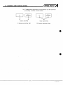
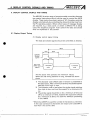
(3) Grounding wiring
(a) Use class 3 grounding (Grounding resistance 1008 or
less). Where possible', ground the PC independently of
other equipment.
(b) Use 2mm2 (14AWG) or larger cable for grounding.
(c) The grounding point should be as near to the PC as
possible.
The grounding cable length should be minimal.
(d) The unit will still operate if ~t is not grounded.
5. LOADING AND INSTALLATION
/MELSEC
(e) if independent grounding is impractical, use the common
grounding method shown below.
equipment
equipment
Class 3 grounding
Class 3 grounding
(1) Exclusive grounding. Best
(2) Common grounding. Good
/MELSEC
5. LOADING AND INSTALLATION
5.3.2 Output unit wiring
(1) Connect~onwith sink output unit (AY40, AY41, AY42, AY50,
AY51, AOJ2-E24T, AOJ2-E28DT, AOJ2-E56DT)
Connection with the AY40 output unit is shown below. The I10
numbers used In t h ~ sexample assume that the AY40 is loaded
in slot 0 of the main base unit.
TB16
YOD
TB19
12124V DC
TB20
OV
100/200V AC
LG
TB20
-1
(+
12124V DC
-
4
*I
"1: The LG terminal must always be grounded.
'
. 5.
/MELSEC
LOADING AND INSTALLATION
'
(2) Connection with source output unit(AY80, AY81)
Connection with the AY80 output unit is shown below. The I10
numbers used in this example assume that the AY80 is loaded
in slot 0 of the main base unit.
. .
* I : The LG terminal must always be grounded.
/MELSEC
6. DISPLAY CONTROL SIGNALS AND TIMING
6. DISPLAY CONTROL SIGNALS AND TIMING
.
.
The MELSEC-A series range of programmable controllers features
two special instructions which may be used to control the A6FD
display. These instructions load a series of 16" characters onto the
display automatically by controlling the data and strobe lines from
the PC operating system. Where other types of message display
are required, e.g. a slow scroll, or where a different PC is being
used, the sequence program must control the data and strobe
lines as explained in this section.
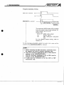
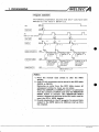
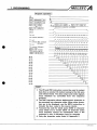
6.1 Display Output Timing
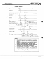
(1) Display control signal timing
The data and strobe signals should be controlled as follows:
30ms
4
5rns
STROBE
(Strobe
s~gnal)
DO to D7
(AGFD data
s~gnals)
-
1oms
1r - -- - - - -
T
I-(,(',,
1 character
code
C
I
I
t
1 character
code
All the above time periods are minimum values.
Where the I10 wiring distance is long, increase the above
times.
1) The character code (ASCII code in binary) is presented to
the data inputs. After a minimum of 5ms, the strobe signal a
switches from high t o low.
2) The character code is read when the strobe signal switches
from high to low, and must be present for a minimum of 5
ms.
3) The strobe signal should be on for a minimum of 5ms and
off for a minimum of IOms, however the cycle time should
be a minimum of 30ms. (To allow for software processing
in the A6FD)
"When the A3HCPU is used the number of characters is unlimited.
In this case consecut~vecharacters are output until code OOH is
read from the source data.
6. DISPLAY CONTROL SIGNALS AND TIMING
POINT
/MELSEC
(
1. When the AGFD is being used in a remote I10 station
(i.e. in the MELSEC-NET datalink network) the PR and
PRC instructions cannot be used and the sequence
program must control the data and strobe signals.
/MELSEC
6. DISPLAY CONTROL SIGNALS AND TIMING
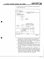
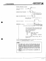
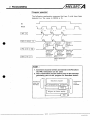
(2) The PR and PRC instructions generate the following data and
strobe signal timlngs.
Dlsplay command
FO Comment source devlce
YO Head output address to whlch A6FD
connected
FO comment
I
ABCDEFGHIJKLMNO
IS
1
Output unlt
OFmredge
The PRC ~nstructlonIS
executed on the leadlng
of the Input s~gnal.
Display
command
ASCII code
Strobe slgnal yg
PRC lnstructlon 0
execut~onflag Y9
)
Durat~on
T
P
R
C
execution
complete
1) The comment data associated with the source device is
displayed via the output module at head address YO.
2) One character is output every 30ms, the total processing
time is therefore 30 x 16 = 480ms.
Processing of the PR and PRC instructions is independent of
the PC scan time and does not effect it.
3) The strobe s~gnalis generated automatically when the PR
and PRC instructions are executed. The strobe signal
causes the characters on the display t o shift one space t o
the left.
4) The PRC instruction execution flag is switched on t o
indicate that the character codes are being output. This
remains on until all 16 characters have been displayed.
It should be used as an Interlock in the sequence program
to prevent the display instruction from being repeated
before all 16 characters have been displayed.
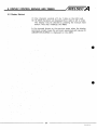
6. DISPLAY CONTROL SIGNALS AND TIMING
6.2 Display Method
/MELSEC
,
(1) One character consists of 5 by 7 dots on the LED (red).
(2) 16 ASCII characters are displayed from right t o left in order.
The display may be cleared by pressing the manual reset
button. This also initializes the A6FD.
I
,
.
.
. In, the example shown on the previous page, when the display
command contact closes the comment associated with device FO
(ABCDEFGHIJKLMNO) is displayed 'on the A6FD.
/MELSEC
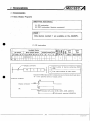
7. PROGRAMMING
7. PROGRAMMING
7.1 Basic D.isplay Programs
. . .
'(1) PR instruction
(2) PRC instruction (device comment)
Only devices marked @ are available on the AOJ2CPU.
(1) PR instruction
levice
revice
Constant Pointer Level
A I Z V K
H
P
I
N
Q c L~
Po w P
m p nw
,
;, E= t; 4
g % Z z;=
7
/----D~splay
Carry
Error
Flag
M9012
M9010 M9011
0
-
0
0
command
O ~ ~ t p uthe
t s ASCII data stored In consecutive source dev~cesstartlng at dev~ce
"S" to the s p e c ~ f ~ eserles
d
of output points.
D~splaycommand
3
OFF
-
Executed only once (Al(E), A2(E), A3(E), A3HCPU)
Continuously executed (AOJ2CPU)
.7-1
1% (NA) 66139-A
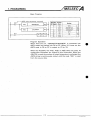
Basic Program
-ASCII
code
ASC
conversion
command
ABCDEFGH
DO
ASC
Program Operation
When X I 0 turns on, "ABCDEFGHIJKLMNOP" is converted into
ASCll codes and stored into DO to D7. When X I 1 turns on, the
ASCll code in DO to D7 is output to YO to Y9.
When the AOJ2CPU, the AI(E), A2(E) or A3(E) CPUs are used, 16
consecutive characters are output by this instruction. When the
A3HCPU is used the number of output'characters is unlimited, the
ASCll string is cont~nuouslyoutput until the code "OOH" is read
from the souce data.
/MELSEC
7. PROGRAMMING
Program Operation Timing
ASCll code
command
conversion
ON
XI0
( A S C ( A B CD E F G H J D O
Stores ASCll code "A
to H" (8 characters f r o m
A to H) into DO to D3.
Stores ASCll code "I to P" (8 character from I to
P) Into D4 to D7.
-----
I(
(s executed
$+AI
Continuously executed (AOJ2CPU)
Executed only once
(E),;ZIE~,*,~;~
The 16-character ASCll code stored in DO
to 7 (8 points) are output from the output
unit at head address YO.
Outputs used YO t o 9.
Output data
YO to Y7: ASCll code output
Y8:
Strobe signal
Y9:
PR instruction execution
flag
For the display output tim~ng, refer t o
Section 6.1.
1
The data dlsplayed on the A6FD IS shlfted from rlght to left In order until the
complete strlng ABCDEFGHIJKLMNOP IS dlsplayed.
I
POINT
(
1. The ASCll codes used for the PR instruction may be
generated using the ASC instruction (alphanumeric
character t o ASCll code conversion) or may be stored i n
the PC device inemory after using t h e List Test function
t o load the alphanumeric data into the source data
registers.
2. Devices t o which the PR instruction is applicable are
marked 0.
'
A
/MELSEC
.7. PROGRAMMING
X . Y M L B F T C D W R A O A l b Z V K
s 0 0 0 0 0 O 0 0 0 0 0
D
b e ,v,
no a P g
Constant Pointer Level
Word (16-bit) device
Bit device
.
,
Available Device
H
P
I
N
v , . ~n a
.-,8 E
6%;6''
0 0
Carry
Flag
Error
Flag
M9012
M9010 M9011
0
-
7
0
POINT
% 4
I
Only devices marked O are available on the AOJZCPU.
~ i s ~ l acommand
;
*
. .
Outputs the alphanumeric comment ass~gnedto the specified source devlce.
Executton cond~tlon
-
'
,
0N
,
Display command'
'
------------ 1
PRC
.'
.
I
I
,
Executed only once (Al(E), A2(E), A3(E), A3HCPU)
Continuously executed (AOJSCPU)
.
>
Basic Program
.
SET
Coding
L
FO ,
I
I
I
1
.,
I
Number Instrucof S t e m tion
1
I
SET
4
PRC
11
LD
12
15
1
RST
I
Device
1
FO
I
FO
I
YO
XI1
I
I
FO
I
I
END
Program Operation '
When X I 0 is turned on, FO is turned on and, at the same time, the
comment-of FO(ASCII code) is output to YO to Y9.
I
In this case, the FO comment ) ABCDEFGHIJKLMNO has already
been entered as comment data.
/MELSEC
7. PROGRAMMING
Program Operation Timing
1-
IS
executed
I
Executed only once (Al(E), A2(E),
A3(E)1 A3HCPU)
JCont~nuously
I executed
(AOJ2CPU)
The comment (ASCII code) of FO is output
from the output unit at head address YO.
Used outputs are YO t o 9.
Output data
YO to Y7: ASCII code output
Y8:
Strobe signal
Y9:
PRC instruction execution
flag
For the display output timing, refer t o
Section 6.1
The data d~splayedon the AGFD
IS
sh~ftedfrom right to left In order until the
complete strlng ABCDEFGHIJKLMNOP
POINT
IS
d~splayed
I
1. Before executing the PRC instruction, comments must
be entered into the PC memory comment area.
2. Only 128 comments (dedicated t o FO t o F127) may be
entered on the Al(E)CPU(P21/R21).
Only 95 comments (dedicated t o FO t o F94) may be
entered on the AOJ2CPU(P21/R21).
3. F coils must be switched on by the OUT or SET
instructions only.
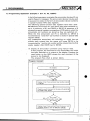
7.2 Programming Application Examples 1 (For A l , A2, A3CPU)
,
. . _
-
7
In the following program examples the annunciator devices (F) are
used t o flag error messages. The annunc~atordevices may be used
to queue error codes (in the form of annunciator device numbers)
in special function FlFO data registers.
The following special function data registers have been used:
D9124(stores the number of F coils which have been switched on,
up to a maximum of 8.) and D9125 t o D9132 ( A sequence of 8
consecutive special registers arranged as a FlFO table in which the
annunciator coil numbers are stored as they are switched on).
When the first annunciator coil (F) is switched on, D9124 is
incremented by 1 and the F coil number is stored in special data
register D9125.
Any subsequent annunciator coil switching on which has not
alrea'dy been entered into the queue will cause D9124 t o be
incremented by 1 and its coil number will be entered into the first
empty register after D9125 (up t o D9132).
.
, ,
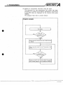
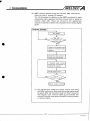
. (1) Display of annunciator comment using manual reset.
f
i
In this program, the comment for any annunciator coil which
has been switched on is output t o the display. Pressing the
reset button on the A6FD causes the next comment i n the
queue to be displayed.
The program flow chart is shown below.
Program 'Concept
I
r.
D~splayof next F c o ~comment
l
from the queue ( c o ~ l
numbers stored rn one of D9126 to D9132).
1
7-6
,
'
1
I
I
1
I
/MELSEC
7. PROGRAMMING
Program Example
I
I
P O
I.) Fallure occurence flag
Fallure occurence flag
Pulse generated by MO
to read f ~ r s tF number
Manual reset (from A6FD)
*2
Manual reset
~ d d s1 to the ~ n d e x
reglster V untll the
value In V IS greater
than the number of F
coils detected.
Transfers F toll number to Index reglster 2.
,,,,
u
=
.
Dlsplays the comment
ass~gnedto the F coll.
3
K
[>Q1?4O
Resets Index reglster V
when all F toll comments have been displayed or ~f no F corls
have been detected
I
L Program
*I : /
1-
*2:
Explanation
1
>= / ~ 9 1 2 4 KI1 ] ...... Continuity
when the number of detected F coil "on" occurences is one or
more.
................ The reset switch is wired to input XO.
When the reset button is released, (i.e.
XO goes from on to off) a pulse is output
on M2. This prevents the PRC instruction from being executed while the
A6FD is being reset.
>= D91241vj ........ Allows 1 to be added to index register V
if the value in D9124 is greater than that
In V.
MOV I D 9 1 2 4 " I ~...... Moves the contents of data register
D9124, indexed by V, (i.e. D(9124 4- V))
to index reaister Z.
~ 0 ' 1 ~ 8] 0......... Displays the appropriate F coil comment on the A6FD wired to outputs Y80
-- Y8F. The F coil number is specified as
FO indexed by Z (i.e. F(0-I-Z).
< = D 9 1 2 4 1 ~........
]
Checks that all F coil "on" occurences
have been processed. If they have, the
index register V is reset t o 0, and the
program will repeat its operation.
*3:
1
(4:
1
*5:
1 PRCI
"6:
1
I
1
-
I
~
/MELSEC
7. PROGRAMMING
I Proaram o ~ e r a t i o n1
The following explanation assumes that two F coils have been
detected (i.e. the value in D9124 is 2).
1
XO
OFF
(Manual reset sw~tch)
wl
OFF
(INCIVI
OFF
+I
V = l
k,
+I
v = 2
V = l
.
I MOV I D9124' 1 V ]
,
OFF
Transfers data
In D(9124 4- 1)
,Giq-qq
appropriate
comment.
1-
OFF
POINT
1
1. Press the manual reset switch t o clear the A6FD
display.
2. Only 8 F coil occurences can be stored in the FlFO table
(D9125 t o D9132).
Removing an entry from the FlFO table causes all
subsequent entires t o move up one place.
When the AS(E)CPU or A3HCPU is used, 1 i s subtracted
from the contents of D9124 each time the INDICATOR
RESET button is pressed. (The INDICATOR RESET
button is located on the front of the CPU and is used t o
reset the CPU's ASCII display).
3. Provide interlocks i n the PC program t o prevent data
output t o the A6FD before its 200msec start-up time
has elapsed.
,
7-8
IB (NA) 66139-A
/MELSEC
7. PROGRAMMING
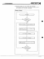
(2) Display of annunciator comment using PC ,timer
The comment for any annunciator coil which has been
switched on is output to the display. Successive F coil entries
in the FIFO table are displayed by the internal clock pulse
(M9033).
The program flow chart is shown below:
Program Concept
]
D~splayof next F c o ~ comment
l
from the queue
( c o ~ number
l
stored In one of D9125 t o D9132)
I
/MELSEC
'7. PROGRAMMING .
I
Program ~ x a m ~ l e
..
..
k:
-
.'
I
.
:MCr
>
Adds 1 t o V
M9033 IS on,
D9124 B V
.
nau
D9124
PRC
F@
K
when
when
z
3
Transfers F c o ~ numbe;
l
number from D(9124+
V) to 2.
YFJB
3
PRC execut~on
Dlsplays the relevant F
coil comment.
i
=
Failure occurrence flag
.
,
Clears data in V ~fD9124
5 V or D9124 = 0
Resets V when D9124
V or D9124 = 0.
K
~ 9 1 2 4 6
I Instruction Explanation I
1
'"1:I > = I D 9 1 2 4 / ~ 1 ....... Continuity when the number of de.
tected F coil "on" occurences is one or
more.
"2: M9033 ..................... Special function contacts. Close every 1
second.
.
"3: > = ~ 9 1 2 4v1 ........ Allows 1 to be added t o index register V
if the value.in D9124 is greater than that
in V.
"4:
~ 9 1 2 4 ~.. 1...~Moves the contents of data register
D9124, indexed by V, (i.e. D(9124 4- V))
to index register 2.
'5:
.......... Displ'ays the appropriate F coil comment on the A6FD wired to outputs Y80
-- Y8F. The F coil number is specified
as FO indexed by Z. (i.e. F(O+Z)).
"6: <= 1 ~ 9 1 2 4 1.........
~
Checks that all F coil "on" occurences
have been processed. if they have, the
index register V is reset t o 0 and the
program will repeat its operation.
1
I
I.
1 MOWI
I
1-
.
1
f
I
/MELSEC
7. PROGRAMMING
/ Program operation I
The following explanation assumes that two F coils have been
detected (i.e. the value in D9124 is 2).
lndexes FO
by Z and
MOV
I
KO
appropriate
COmmenf
IV
. .
POINT
When D9124
v=o
SV
lndexes FO
by Z and
outputs
appropriate
comment
----
1
1. Comments must be written and stored in the PC before
the PRC instruction can be used.
2.:The CJ instruction may be used to jump to the message
generating part of the program as described below:
Sequence program
Cond~tional
jump not
activated
1
-FEND
Program for failure display
/MELSEC
7. PROGRAMMING
(3) Alternate display of F coil number and comment.
This program example outputs a numerical variable (i.e. the F
coil number) and a comment alternately.
.
*
Program Concept
I
No display
Flrst F coil number 1s read and transferred to Z.
1
Appropriate F colt number
blnary to ASCII equ~vllant.
IS
converted from
II
v
F toll number is displayed.
v
F toll comment is displayed
1
I
1
check for next F toll in the queue by pressing the
AGFD reset button.
7-12
IB (NA) 66139-A
Program Example
88-C>=
K
DQ1?4 1
I
3
::
94.
CPLs
::sea?
VgP
98. ::
18~3FT=
09124 V
3
,
~
c
I
N
no!!
n3
::
[1!1124
*I
c n s ~B g~4 i
-
CBC[*
*2
-
c['lZ
7
-
:
-
-
1 :"~ c , :;n~
-Jl'a~=
:
215-C=
I
1
=
2;l-c
+=
248,
nl
3
[,3124
T 1:;
!:kt
,
P
'3
CsFL
*4
c+
P
[I:?
no"*
*6
[.:I
P H
~ 1p 8 : p~
~
3
In3
>
[#re
3
Transfer F number to Z.
Transfers
F) to D1O.2046H (character code (S),
Converts failure detection number in
Z into BCD and transfers it to 020.
Dividesfailure detection number into
3 digits and stores them into 020 to
D22.
3 Shifts 16 bits in D21 to the left by 8
bits.
1 ~ 2 1 ) Executes addition of values in 022
and 021.
[I: 1
3 Logical addition of 3030H and D21
and stores the result into D21.
[':"
["@
"@
i
'
2
P
*5
Pulse for first F number display.
JJ
-
2 4 t.
I>
Manual reset pulse.
CPLF
H2
3
X9=manual reset input.
Y69=PR and PRC execution flag.
c
l
l 3 Add 1 to v.
I
n1
128.
CRB
H8
Y21
c,,lc,pP!li:c,
q
Transfers 021 data to D l l .
Logical addition of 2030H and D20
[ # ? @ 3 data, and stores the result into 020.
1111
,
Transfers D20 data to 012.
*7
Ci,qI:IF
!e2e
*8
:pR
j
[ole
INC
,,I:IIIP
L
Transfers 2020H in blocks to 013 to
!
:Guts failure detection number to
Y60 with PR instruction.
[email protected]
[*38
3
[':I
3
Executes PR instruction once.
Outputs comment relevantto F(O+Z)
to Y60 with PRC instruction.
D31
P
18'
3
3
11
3
Executes PRC instruction once.
Executes PR and PRC instructions
alternately depending on conditions
of TI, M20, and M21.
Clears V data if D9124dV or D9124
= 0.
[>'rl24@
re
;:
TI
::
*10
Alternating timers.
C l R C U l T EN[)
(SP) indicates character code for space.
/MELSEC
'7. PROGRAMMING
I Instruction
Explanation
I
I
.
. .
I
*I
: ~ 0 ~ ~ 1 ~ 2 DIO
0 4 6 ......
1
Transfers the character codes for
space (H20) and "F" H46 to data
register D l 0.
1
"2: DIS'I ~ 2 0 D1 ~
.
, ,
BCD coded digits in
D20 and places the least significant in
D20 the middle digit in ~ 2 and
1 the
most significant in D22. The annunciator coil number digits have therefore been placed in three consecutive
registers. (Example: For coil F123 the
digits will be stored as follows, 3 i n
D20, 2 in D21 and 1 in D22.)
,
I
"3: ( SFLP1 ~ 2 (1 ~ ............
8
Shifts the value in D21 8 bits to the left
(Example: D21 contains the data
8
,
+
o I ' K I ~...... Takes the three
.
0002. This step of the program will
change that to 0200.)
I
J
. *4:(+'JD221D21)
,
.
.
,
............. Adds D22 and D21 and stores the
result in D21. (Example: Contents of
D21 is 0200, contents of 022 is 0001.
, .
This step of the program stores 0201
in D21.)
. _
*,5:
I W O R ~ ~ H ~ O ~ OI ......
~ D ~Logical
I
addition of H30 to each digit
in D21 to convert from BCD t o ASCll
i ~ x a m ~ l eContents
:
of D21 is now
H3231; i.e. ASCll code for 2 and 1)
/
*6: wORpI~ 2 0 3 (0 ~ 2 ( 0..... Logical addition of H2030 t o digits in
D20 (Example: Contents of D20 is
now H2033, i.e. ASCll code for space
and 3.)
1
1
*7: ~ ~ 0 ~ ' ( " 2 0 2 0 ( ~...1 Transfers
3(~5
space codes H20 into each
byte of the five word registers D l 3 to
D1.7.
/MELSEC
7. PROGRAMMING
1-
*8:
............. Outputs the 16 character codes from
D l 0 to D l 7 to outputs Y60 to Y67 in
A6FD compatible format.
-
Character codes sourse
Upper
8 bits
Lower
8 b~ts
-
- --h
CV
6 .
n
-
7
o
0
.
-
0
IIIIII
o o , - ~ ~ o r n c ~ ~ o u ,
CVrnrnrnNb
C
Order of
transrn~ss~on
I
I
*9: PRC ( FOz( ~ 6 0........... Outputs the comment assigned to the
appropriate F coil to.outputs Y60 to
Y67 in A6FD compatible format.
"10: T0,Tl flickercircuit ..... . Calls the PR and PRC instructions
alternately.
/MELSEC
7. PROGRAMMING,
I Program Operation I
.
.
.
I
FMOVP "2020
I D l 3 I K5 I
T I (10-second clock)
Y69
PR and PRC execution flags
\ \
!"d
w
D~splayof
POINT
D9125 data
-,- - D~splayof
D9126 data
]
1. When the PR instruction is executed data is transmitted
starting from the lower byte of the source data head
address.
Similarly, the lower byte of the subsequent string of
registers is transmitted before the upper byte.
2. Interlocks must be provided t o prevent the PR and PRC
instructions from' being called simultaneouslv.
3. Alternating output is provided by T I (5-second clock).
Interlocks are provided using the INC(P) and MOV(P)
instructions so that the PR instruction is executed once
during the OFF period of T I and the PRC instruction
executed once during the ON period.
/MELSEC
7. PROGRAMMING
(4) A6FD control without using the PR and PRC instructions
(Also for use in remote It0 station)
The 16 characters for display on the A6FD are stored in eight
consecutive data registers and then moved onto a series of
internal relays (M). These are moved to the appropriate
outputs in batches of 8 bits (one character) and a strobe signal
given.
Program Concept
I
nnunc~atorcol
Codes for I6 characters ar
stored In consecut~vedat
(1) The 16 character codes are output one by one using
the'MOV instruction. Note that the strobe signal must
be given after the character code has been moved t o
the outputs. Care must be taken to co-ordinate this
with the link scan time when the A6FD is being used at
a remote station.
/MELSEC
7. PROGRAMMING
I Instruction
"1 :
Explanation
I
I ASCIABCDEFGH I DO] ... The
ASC instruction coverts alphanumeric characters into ASCll code and
stores it into four consecutive devices
beginning with the one specified.
(Instruction executlon)
( ASC ( ABCDEFGH 1 DO 1
Character codes
shown i n hexadeclmal.
"2:
1 MOVIDO~~
1
4 .....
~ Transfers
0
the ASCll code bit pattern
onto MO t o M I 5 (K4MO).
lnstructlon executlon
"3: Timers TO, TI, T2 ...... TO and T I time movement of the ASCll
bit patterns to the outputs.
T2 provides the strobe signal.
T2 coil
TO contact
I
I
-1
I
I
I
T1 contact
(NIC contact)
I
T2 contact
I
/
ASCII character moved
when contact 1s closed
*4: BSFL'(MI~O~
K17
-4-b
10rnsec
-4-b
10msec
slgnal provlded
-Strobe
when contact IS closed
1 ... Shifts 17 bits starting at M I 3 0 one bit t o
the left each time TO switches on.
Used as a 1-character code sending
flag.
I
1
"5: MOVP]K ~ M O / K ~ Y
....~ Outputs
O
one character code of K2MO
("41H" in lower 8 bits of DO) t o K2Y60.
(Hexadecimal)
'
Moves one character code from K2MO
t o outputs Y60 -- Y67.
Instructton
execution
For example, the display output timing for M I 3 1 is shown below.
0N
MI31
OFF-
MI32
OFF
MoVp K2Mo
MOVp(W
Y60
to
K2y60]
I
TO and TI.
n'
1s executed o n c e )
(Instruct~onis executed once.)
ASCll code output
(Character code) H
Y67
. -.
Y68
1
Controlled by h ~ g hspeed tlrners
-
Y68 Strobe s~gnal1
-
T2 (strobe output t ~ m e r )
A6FD ASCll code read tlrnlng
+++*
41H
42H
1
I
Strobe s ~ g n a lIS output after
ACrii
code (character code) is
p ~ ~ ~ ~ d e d .
/MELSEC
7. PROGRAMMING
I Program operation I
X9
MI48
ASC ABCDEFGH
ASC
1
I DO I
IJKLMNOP
0
D4
I DO I K4MO
to
MOV I D7 1 K4M112
MOV
"Operation execution complete
MI28
I
MI~O
n
TO COII
i
u
U
I
u
u
u u ~ u y i -
TO contact (50msec)
n
o
T I coil
T I contact (NIC contact)
(50msec)
T2 cod
n
m
T2 contact (50msec)
Y60 to Y67 .
(ASCII code output)
Y68 (strobe signal)
n- n n n_n
10msec
POINT
t i 3 7
u
U
I
u u~
I-I-~
u-71 u u u u
q ~ nn
n n
u
LL~
1
n k n n n n n n n _ l l n n n n n
I
1. The PR and PRC instruction cannot be used t o output
data from a remote I10 station (owing t o the link scan
and refresh times). The data output and strobe signals
must therefore be controlled from- the sequence.
program.
2. The ASC instruction allows alphanumeric character t o
be converted into character codes. When other characters are t o be displayed, use the MOV instruction t o
transfer the hex. code t o the source device.
3. Transmit the code for blank space (H20) t o character
areas which are t o remain blank. 16 character codes
must therefore always be transmitted even if the
message is only 8 characters long for example.
4. Only use character codes listed i n Appendix 2.
-
/MELSEC
7. PROGRAMMING
7.3 Programming Application Example 2 (For AOJZCPU)
A6FD control programs are different for the AOJ2CPU.
he following example displays failure numbers generated when
inputs are switched on.
.
.
Program Con'cept
Any other F colls on,
,
'
D~splayof nest annunciator toll comment
*,:Pressing the A6FD manual reset button loads the next F
coil number into D9090.
/MELSEC
7. PROGRAMMING
Program Example
0lq
I
14\80
CPLS
CSEl
CPLS
Mi80
CPLS
CSET
36
jKJtoflrespresent
slgnal Inputs
CPLS
451
7
14\@0
failure
CPLS
n\g0
CPLS
'PLS
F7
Dl
9
1
b
=
H
D90031
CPLS
CRST
ISlkl?"
1 0 5 k e r n a lInput for fallure number detection
119069 M l l
1 6 5 bH
0
K
DO
3
C
CPLS
P
R
C
FO
CPRC
F1
3
3
'
J
j
Stores the flrst fallure
number Into 09009.
Stores the number of F
colls whlch have been
switched on
nlOO 3
Resets M9009 as soon
as failure IS removed
M9009
(When fallure occurs,
1 1 ) M9009 turns on.)
CRS1
=
K
2
=
K
3
=
K
4
D O 3
CPRC
F2
CRST
t
I
I
=
K
5
DO
DO
'I
CRST
CPRC
F4
r,RST
CPRC
F5
CRST
CPRC
F6
ERST
=
!
DO
CPRC
F7
CRST
F2
Slnce the PRC lnstructlon In the AOJ2 IS not
Yr120
leadlng edge triggered,
~3
3 . lt IS necessary to convert
external inputs Into
3
pulses DO stores the
current fallure number
F4
This failure IS detected
by the comparison ~ n ~ 8 2 03
structlon and the reF5
3
levant fallure number
comment IS dlsplayed If
't020
other fallures exlst, resettlng the dlsplayed falF6
3
lure number stores the
j'020 3
lowest fallure number
Into D9009 (DO)
'
F7
3
/MELSEC
7. PROGRAMMING
..
7.4 Display of Numerical Variables'
,,
Numerical values may be output using the method described in
Section 7.2 (i.e splitting the number into digits and a d d i n g a ~ 3t 0
o
each digit to change it to .ASCII).
Where this is impractical the SWOGHP-UTLP-FN1 micro computer
software package may be used to change numerical data to the
equivilant ASCII string.
.
.
7-24
IB (NA) 66139-A
.<
8. TEST
/MELSEC
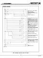
8. TEST
8.1 Pre-Test Checks
Check the following before powering up the A6FD:
1. Installation environment and conditions;
2. Output unit type driving the A6FD;
3. Output unit correctly loaded in base unit;
4. Wiring and connections;
5. Wire guages used;
6. Power and control line fuses; and
7. Supply voltage.
8.2 Test and Adjustment
CPU to RUN.
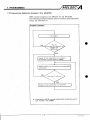
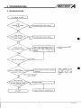
9. TROUBLESHOOTING
No d~splayon AGFD
+
(
,100/200V AC supply
Connect/correct power supply.
No
Good
Check PC CPU
-
No
Good
I
Check error using AGGPP
or A7PU
Refer to troubleshooting sectlon of
A1 (E),A2(E), A3(E), A3HCPU User's
Manual or AOJ2 Programm~ng
Manual
A
LnecK external w i r ~ n gand resume
No Good Check
)
n.
operation.
3
'Check w ~ t hCPU
set to "STOP."
I
Check voltage at the
e ~ g h AGFD
t
~ n p utte r m ~ n als (DO t o D7 and
STROBE) using circuit
tester.
Force data l ~ n e
N0
Good
Repeat checks
1
Consult M ~ t s u b ~ s hrepresentatwe.
t
9-1
IB (NAI 66139-A
lo.
/MELSEC
MAINTENANCE AND lNsPEcTloN
10. MAINTENANCE AND INSPECTION
There are no components in the AGFD which require regular
service or replacement.
The following periodic checks should be made.
v, IS)
5
1
Looseness,
play
Tighten screws
5
s
Remove dust and debris
V)
c
-0
c
8
p
(I)
0
U
3
Corrective action
Check for
Item
t
Loose
terminal
screws
Tlghten screws
Clearance
between
solderless
terminals
Ensure that there IS adequate clearance
between solderless term~nals.
Loose
termlnal
block
Tighten terminal block screws.
'
L ~ n evoltage
Amblent
temperature
Line voltage should be between
85 and 264V AC.
Must be between 0' and 55'C
Must be between 10% and 95% RH
Must be wlthin the speciflcatlons glven in
sectlon 3 1
Fig. 10.1 Check List
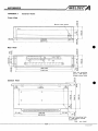
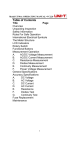
APPENDIX 1
Front View
,. .
External Views
-
,
.,
'
.
*,
,
Manual reset switch
.
N
\
\
A~FD
.
-
\
.
i
*
'
gF
0
RESET
/
.
1
(D
2
;5
co
L
246(9.69)
290(11 42)
28(1.10)
_
)
-
-
s
r'
0
0
N
Rear View
hole 4 x M4 (Metric
thread) screw holes
Bottom View
3711.4611
*
1gO(7.48)
264(10.39)
Main unit mounting hole
4 x M4 (Metric thread)
screw holes
U n ~ t: m m (inch)
/MELSEC
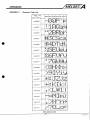
APPENDICES
APPENDIX 2
Character Code List
Lower 4 b ~ t \
s
xxxx0000
(SP)
...........
.I,..!
.
.
.
.
.
.
.....
I....
m
.
i
...
......
....... .mm
xxxx 1001
(SP) indicates space.
APP-2
n
/MELSEC
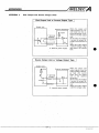
APPENDICES
APPENDIX 3
Sink Output and Source Output Units
Sink Output Unit or Current Output Type
"
Output unit
.
1
-
External equ~pment When the Output unit
output signal is on, current flows from the external equipment, via resistor R, Into the output
.
At this tlme, the voltage
V across the output terminal and its common is
E: External power supply
When the output s~gnal
IS off, the voltage is high
and there 1s no current
flow.
t
Source Output Unit or Voltage Output Type
I
I
Output unit
External equipment
,
t
Y term~nal
(Output)
"
,.
Current I
Voltage V
Common
"
,
.
E Internal power supply
.
,
When the output unlt
output signal IS on, the
output voltage V becomes high and current
flows from the output
unlt to the external
equ~pment.
At thls tlme, the*voltage
V across the output termlnal and its common is
h~gh
When the output s~gnal
IS off, the voltage is low
Index
Page
Character code
Control
Data signal
Digital output modules
Dimensions
Display
Dot matrix
Electrical specifications
Environmental specifications
Grounding
Handling
Inspection
Installation
Interface (internal)
O
I
requirement
LG termlnal
Maintenance
Mounting
Nomenclature
Output modules
Power supply
PR instruction
PRC instruction
Pre-test checks
Remote I10 station
Reset push button
Reset relay
Sink output
Source output
Specifications
Strobe signal
supply voltage
Terminal details
Test and adjustment
Troubleshooting
Voltage, supply
Wirlng
IMPORTANT
1
The components on the printed circuit boards will be daniaged by static electricity, so
avoid handling them directly. If it is .necessary t o handle them take the*following
precautions.
I
.
(1) Ground human body and work bench.
(2) Do not touch the conductive areas of the printed circuit board and its electrical pads
w i t h any non-grounded tools etc.
'
Under no circumstances will Mitsublshl Electrlc be llable or responsible for any consequential damage that may
arise as a result of the installation or use of thls equipment
All examples and diagrams shown In thls manual are intended only as an ald to understanding the text, not t o
guarantee operation. Mltsublsh~Electric will accept no responslbllity for actual use of the product based on these
illustrative examples.
Owlng to the very great varlety in posslble applications of thls equipment, you must satlsfy yourself as to its
suitability for your speclfic application.
1% (NA) 66139-A
+
MlTSUBlSHl ELECTRIC CORPORATION
HE40 OFFICE MITSUBISR DENKI BLDG MARUNOUCHITOKYO 1W TELEX J24532 CABLE MELCO TOKYO
NAGOYA WORKS 1-14. YADA-MINAM15. HIGASHI-KU NAGOYA JAPAN
....
~rted
from
Japan, this manual does not require application to the
Trade and Industry for SeNiCe transaction oermission
-
39-B (8904)MEE
Printed in Japan
Specifications subject to change without notice.