1
SECTION 2
FEASIBILITY STUDY
Solar Design Manual
Contents -Page ii-ii
Section 2- Feasibility Study
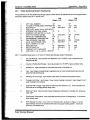
SECTION 2
FEASlBlLlTY STUDY
CONTENTS
Page
2.1
OVERVIEW ............................................................................................................. 2.1
2.2
APPLICATION REVIEW
2.2.1
2.2.2
2.2.3
Data Gathering ...................................................................................................... 2-2
Energy Conservation Alternatives ......................................................................... 2-3
Thermal Load Requirements ...............................................................................2-4
2.3
SIZING/PERFORMANCEANALYSIS .....................................................................
2-6
2.3.1
2.3.2
2.3.3
2.3.4
Computer System Simulation ..................................................................................
2-6
Construction Costs ..................................................................................................
2-8
Economic Evaluation...............................................................................................
2-9
Iteration of Sizing Calculations ................................................................................
2-10
2.4
SYSTEM DESGN DESCRIPTION ....................................................................... 2-10
.........................................................................................2-2
CHECKLISTS
Solar Energy System Goals ....................................................................................2-11
Building Information .................................................................................................
2-12
Site and Environmental Considerations ................................................................
2-16
Energy Conservation Measures ..............................................................................
2-18
Service Hot Water Data................................................... .
,
.....................................
2-22
Space Heating Load Requirements ....................................................................... 2-25
Construction Cost Estimate Summary
Solar Design Manual
....................................................................2-27
Section 2- Feasibilio Study
Contents -Page ii- iii
SECTION 2
FEASIBILITY STUDY
WORKSHEETS
Page
2-1
Estimated Service Hot Water Load Calculation
from Water Usage Measurement ............................................................................2-28
2-2
Estimated toad Calculation from Fuel Consumption Data
for Service Hot Water or Space Heating .................................................................2-29
APPENDIXES
2A
Solar Radiation Considerations ............................................ ..................................2A-1
2.
2B
Guidelines for Using F-CHART Program................................................................
2B-1
2C
Construction Cost Estimation Method .....................................................................2C-1
20
Sample Solar Energy System Design Description Format ................:.....................2D-1
Solar Design Manual
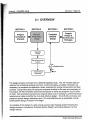
SECTION 1
SECTION 3
SECTION 2
f
SECTION 4
\
*
Complete
Detailed
Design
\
-
f
J
Prepare
Design &
Construction
Packages
\
Application
Analysis
Point
System Design
Description
The design process continues with a detailed feasibility study. The A/E reviews data provided by the conceptual analysis summary, confirms the data, and adds information, as
necessary, to complete the application review checklists for energy conservation and load
analysis. Using these data and computer programs suitable for the size and complexity of
the project, the AIE completes performance analyses to verify and establish size of collector field. Cost estimates and economic analysis follow, and, if necessary, performance/cost
iterations are made to identify the most cost-effective design. The A/E will summarize and
prepare a system design description and, if the cost-effectiveness is acceptable, the detailed system design of Section 3 will begin.
An example of the design of a solar energy service water heating system following this
design process is included as "Example System Design" and follows Section 5 of this
design manual.
Solar Design Mangal
-
Application Review- Page 2-2
Section 2 Feasibility Study
2.2 APPLICATION REVIEW
2.2.1
Data Gathering
During this phase of the design process, an indepth study of the user's
goals (requirements), building, location, environmental and regulatory
conditions, and thermal loads should be performed. Generalized data
gathered during conceptual analysis are confirmed and expanded for use
later in the detail design of systems. This section describes the data
required and provides checklists for identifying and recording important
information.
User's Goals
Information in Checklist 1-1, completed during conceptual design, should
be reviewed and updated, as necessary, and included as Checklist 2-1.
Building Information
The type of building, location, occupancy, and type of conventional
service water heating and space heating systems impact the design and
integration of solar energy systems. In retrofitting solar energy systems
on existing buildings, site visits and surveys should be made to identify
and record those items listed in Checklist 2-2 that appty to the type of
solar energy system being considered. For buildings that are in the
design phase, checklist data can be furnished by the building N E .
Site and Environmental
Conditions
Site-related factors that affect design and performance of active solar
energy systems, subsystems, and components are identified and recorded on Checklist 2-3 during the application review. Important factors
of Checklist 2-3 are discussed briefly here. Appendix 2 A should be
reviewed for a discussion of solar radiation if required by the NE.
Visible portions of solar energy systems, such as collectors, may be
subject to local building code or architectural regulations. Even if not
regulated, the owner may choose to design the system so that it is not
visible from ground level, with perhaps some added cost. Communities
may have ordinances that affect solar access and would restrict intrusion
by adjacent property owners and builders. Some localities impose
additional requirements and restrictions on design and construction. Of
particular importance to solar energy system designs are local requirements to provide double separation between glycol (used for collector
antifreeze fluid) and the potable water system, which would impact
system cost and system performance.
Long-term weather data, such as temperatures, insolation, and wind,
from the closest National Weather Service (NWS) station are usually
applicable. Differences in topographic features between weather stations and building locations may adversely affect weathe r conditions at
specific site locations. Long-term local weather data, if available, should
be consuited. Checking with local residents is helpful in determining
significant weather variance from nearest weather stations. Items of
particular interest are cloudiness/sunshine, wind velocity, and snowfall
and accumulation, if applicable.
Chemical or particulate emissions from nearby operations or facilities
such as incinerators, factories, or processing plants should be consid-
t
Solar Design Manuel
-
Section 2 Feasibili~Study
Application Review
- Page 2 3
ered. These may significantly impair performance, increase maintenance costs, or shorten the life of solar collectors.
Shading of proposed locations for solar collectors by nearby structures
and/or vegetation during all seasons should be determined. Future
potential offsite development, permitted by local building ordinances and
land-use policies, may increase the amount of shading or have other
adverse impacts on collector performance and must be considered here.
2.2-2 Energy Conservation
Alternatives
Successful application of solar heating systems requires that the building
and its energy distribution systems be designed to conserve energy.
Building owners should be encouraged to implement applicable conservation measures prior to or concurrent with installation of solar energy
systems. Energy saved by these conservation measures will reduce the
total building heating load used in designing the solar energy system.
Typical energy conservation measures are listed in Checklist 2-4; some
of the more significant ones are discussed below.
lnsulat ion of Piping Ducts
and Heaters
Air Infiltration Reductlon
Thermal losses from uninsulated or poorly insulated heaters, furnaces,
hot water pipes, and warm air ducts (also cold air ducts) cause hot-water
heaters or furnaces to operate longer to reach the set point temperature.
Often, set temperatures of hot water heaters or space heating thermostats are raised, contributing to further losses. Adding to or improving
insulation on pipes, ducts, and heaters, where applicable, is a low-cost
energy conservation measure.
Infiltration of mid outside air into buildings through cracks, openings, and
gaps around windows and doors increases buifding space heating loads
to such an extent that it is often responsible for as much as 25% of the
building's annual energy consumption. While infiltration tends to increase with wind velocity penetrating the buifding's windward exposures,
negative pressure generated inside the building on roofs and leeward
exposures will also draw cold air into buildings through openings and
gaps.
Tall buildings are subject to stack effects that result from the difference
between indoor and outdoor temperatures. The stack effect originates in
open vertical spaces such as stairwells, elevator shafts, and service
shafts. Potential for the stack effect in tall buildings is always present but
can be minimized by isolating these "chimneys" from occupied areas by
enclosures and doors.
A primary source of energy waste is overventilation, which results from
poorly designed or operated HVAC systems. Building ventilation should
be just sufficient to maintain comfort conditions in occupied areas.
Operation of HVAC systems, particularly operation of dampers and their
air-tightness, should be checked and adjusted to provide only minimum
required exhaust and fresh air flow rates.
Humidity Control
During the heating season, humidification systems vaporize water into
dry ventilating air to increase its moisture and achieve desired humidity
within buildings; additional energy is required to vaporize and heat
moisture added for humidity control. Humidificationsystems may be
Solar Design Manual
-
Section 2 Feasibility Study
Application Review - Page 2-4
designed not only to maintain comfort and health of occupants, but to
preserve materials and prevent drying and cracking of various contents
of buildings. Unless such humidity requirements are indispensable,
relative humidity should be maintained no higher than the level required
for occupants alone.
Setback Thermostats
Thermostat settings should be lowered manually or automaticafty set
back in work areas and office spaces during unoccupied periods. Such
setback should not activate the building's cooling system. Climate, type
of system, and building construction will influence the length of startup
period required to achieve occupied temperature levels.
Waste Heat Recovery
Waste heat may be used to provide energy for space heating and service
hot water systems. Some of the more frequently used waste energy
sources include exhaust air, flue gas, hot condensates, refrigerant hot
gas, hot condenser water, hot water drains, engine exhaust, and cooling
towers. Use of these waste heat sources can significantly reduce
heating energy requirements.
Servlce Water Energy Savlngs
Consideration should be given to reducing hot water consumption,
reducing hot water temperatures, and reducing heat losses from piping.
If circulating hot water loops are used, flow rates should be adjusted to
the minimum requiredto maintain hot water at the minimum acceptable
temperature at the use points, and circulation should be limited by
timeclock to the hours buildings are occupied.
2.2.3 Thermal Load
A thorough understanding of expected hot water andfor space heating
needs of facilities is essential for designing solar energy systems. The
thermal load of interest is the total load, which includes energy to satisfy
Requirements
all hot water use in the building -- showers, lavatories, kitchens, cleaning, and processing - and all space heating requirements, as well as the
energy required to make up the losses suffered in generating and
distributing the hot water and hot air.
For retrofitting existing buildings, existing records of hot water and/or
space heating fuel usage are excellent sources of data to determine the
thermal loads. If energy conservation measures are to be implemented
concurrent with solar energy system installation, thermal credit must be
allowed for these measures. Short-term monitoring of toads in question
also can be performed as an alternative to existing records (or if no
records are available). This could be done by installing additional water
meters, fuel meters, and/or Btu meters. (See Section 3.5 fur a discussion of Btu meters.)
For new buildings, the AIE can furnish design load data. If possible,
such design data should be checked by comparison with actual loads for
buildings of similar type, occupancy, and usage. In case of conflict,
actual load data from similar buildings should be used.
In addition to total energy requirements on a daily, monthly, and annual
basis, daily load profiles are an important consideration for design of
solar energy systems. For example, a constant daytime load profile is
ideally suited for solar energy systems because energy is used when it is
collected. This allows the collectors to operate at lower temperatures
-
Section 2 Feasibilitv Studv
Av~~ication
Review
- Pane 2-5
and at higher thermal efficiencies. In addition, overall system efficiencies
are higher because little or no energy is stored for overnight use, reducing overnight thermal losses from system piping, storage units, and
components. Because less storage volume (or none) is required, total
capital costs are minimized.
The A/E should select any low temperature loads that have been found
in this survey as the primary target for solar energy system applications,
as low temperature loads are most appropriate for solar heating, allowing
collectors to operate at higher efficiencies and reducing storage volume
required. Ventilation air preheating, for example, may be accomplished
efficiently with no storage.
Checklist 2-5 should be completed as accurately as possible. If historical hot water consumption data are available, the equation in Worksheet 2-1 can be used to calculate total thermal load. If fuel use data is
available, the method in Worksheet 2-2 can be used to convert this data
into thermal load.
Hot Water Load
Because of the significant impact of the daily hot water use profile on
solar energy system designs, usage data in Checklist 2-5 as to time of
use and flow rates should be determined as carefully as possible.
Information about existing or to-be-installed service water heating '
systems, as requested in Checklist 2-5, is an important consideration for
integrating solar energy systems and should be carefully researched and
documented on checklists.
'
If a hot water recirculation system is used, heat losses from the system
must be included in the load calculation. The hot water recirculation load
can be calculated as shown in Checklist 2-5.
Space Heatlng Load
Checklist 2-6 should be completed as accurately as possible. Historical
space heating fuel data can be converted to thermal load using conversion factors and conversion efficiencies in Worksheet 2-2. If fuel data
are not available, heating load can be estimated using data in Checklist 2-6 and the ASHRAE Handbook, 1985, Fundamentals Volume, Load
Energy Calculations Section. Other methods of calculating heating
design loads may be found in the Heating Load Chapter of the Fundamentals Volume.
Space heating loads vary from month to month throughout the year and
depend on intensity and seasonal use of the building space. Daily and
monthly profiles of space heating loads should be prepared for intended
applications using information provided in Checklist 2-6. Detailed
information on existing or to-be-installed space heating systems is important input for solar energy system integration, and all available information should be recorded in Checklist 2-6.
1
Solar Design Manltal
-
SizinglPerformance Analysis
Section 2 Feasibility Study
2.3.1 Computer System
Simulation
- Page 2-6
For the feasibility study, a more accurate method of estimating solar
energy system performance is needed than the tabular data used in the
conceptual analysis of Section I .
Many sophisticated proprietary computer programs are available that can
perform this function. The A/E may refer to the ASHRAE publication, "A
Bibliography of Available Computer Programs in the Area of Heating,
Ventilating, Air-conditioning and Refrigeration" (1986 Edition, Code
COMB\B)for further information on computer simulation programs. This
publication provides information on programs that are available, what the
programs do, and who to contact for more information.
NOTE: The F-CHART program
is not proprietary. This program
Is used as an example; such
use does not constitute an
endorsement by ASHRAE as
ASHRAE cannot endorse any
computer simulation model.
For purposes of this manual, the F-CHART program was used to demonstrate an example simulation program in the Example System Design,
following Section 5 of this design manual (See note in margin).
For solar energy systems described in this manual, a system simulation
computer program yielding monthly performance estimates is best
suited for overall system performance analyses. Such a program should
allow estimation of the monthly solar fraction and a study of the effects of
parameter changes on solar fraction. Parameters that should be varied
include total colledor area, collector characteristics, storage capacity,
load heat exchanger characteristics, flow rate of collector fluids, desired
hot water temperature, cold water supply temperature, and collector
slope and orientation. F-CHART programs used with mainframe computers (Version 4.2) and microcomputers (Version 5) are available. Although Version 4.2 has more capability, it is more difficultto use, and
Version 5 is recommended. Input data required for running this program
are described in Appendix 28. Considerations for some of the important
input parameters are discussed as follows.
Building load data were calculated in Section 2.2.3 above. For service
water heating applications, F-CHART requires load usage rate inputs in
average gal/day. If a hot water recirculation system is selected, two
methods can be used to account for this load (loss):
..
If recirculated water is supplied from an auxiliary storage
if
tank at a temperature close to the set temperature
recirculation is continuous over the 24-hr day, losses to
the environment can be accounted for by increasing the
UA of the auxitiary storage tank.
a
For any other case, an estimate of the losses can be
added to the actual service hot water load by increasing
the daily hot water usage.
Single collector performance parameters determined according to
ASHRAE Standard 93-86, "Method of Testing to Determine Thermal
Performance"(or its earlier version, 93-77), by a recognized testing
organization such as the Solar Rating and Certification Corporation
Solar Design Manual
-
Sizing/Perfonnance Analysis
Section 2 Feasibility Study
- Page 2-7
SRCC) are available from manufacturers and should be used if a
specific collector has been selected. If selection of a particular model of
;olar collector cannot be made during the feasibility phase, performance
:alculations can be performed by using parameters of collector types
nost likely to be used, such as those given in Section 1.5.1. If evacuHed collectors are considered, incidence angle modifiers can signifi:antly affect performance predictions and must be included in the
:alculation.
Zollector field orientations and collector slope angles must be selected.
The preferred field orientation is facing true south (in the Northern
have minor impacts on solar
Hemisphere), but deviations up to -t-30"
energy system performance. Deviations from true south may be necessary and desirable for roof-mounted collectors to conform with building
constraints. The preferred collector slope angle is equal to the latitude
for year-round heating, such as hot water; higher slope angles should be
used if most solar heating is required in the winter, such as for space
heating. The preferred slope angle for winter space heating is equal to
the latitude plus 15". If heating is required only or mostly during the
summer, then slope angles should be as much as 15' less than latitude.
Another important parameter of solar energy systems that must be
selected is the effectiveness of the collector loop heat exchanger, if one
is used. For an appropriately sized external heat exchanger, effectiveness can be between 0.6 and 0.9; an effectiveness of 0.6 should be used
for feasibility determinations. An immersed-type heat exchanger in the
collector loop is not recommended in any of the system designs discussed in this manual.
Adjustment of Simulation
Computer Programs
Extensive monitoring by the Department of ~ n e r (DOE)
g ~ of many
operating solar energy systems from 1981 to 1986 has led to the conclusion that solar energy system performance rarely achieved that predicted
by system simulation computer programs. Principal factors cited to
support this conclusion are:
.
.
.
Actual operating conditions for collector arrays vary
considerably from the ideal conditions used for singlecollector ASHRAE Standard 93 performance tests
Thermal losses from collector connections and piping in
a large system are higher than those from an idealized
single-collector test
Performance of multiple collectors arranged in rows and
banks is usually not as good as that of a single collector
tested to ASHRAE Standard 93
Design and construction decisions may prevent operation at optimum conditions for the site
.
Construction discrepancies in the as-built solar energy
system may degrade performance below the design performance
I
Solar Design Manual
-
Section 2 Feasibility Study
Sizin~/Pelrformance
A ndysis- Page 2-8
.
Actual load profiles may use collected solar energy less
efficiently than the program predicts. For example,
F-CHART calculations are based on a constant daily
load, with a typical residential use profile, 7 days a week.
This does not model a 5-day office building exactly.
Note: A constant daily load for 5 days a week may be
spread evenly over 7 days to mn the F-CHART
program; however, F-CHART will overestimate 5-day
system performance by about 10%.
Therefore the approximate upper limit of preliminary performance
estimates of solar energy systems can be established using computer
simulation programs. The estimated solar energy delivered to the load
should then be reduced by 20% to perform collector array sizing calculations.
The example simulation program should be run with input data from the
conceptual analysis (Section 1) updated by the work in this section. The
program should be rerun, varying selected system parameters, until the
system output approaches the design goal. The final collector area and
other system characteristics determined in these runs can then be used
in the construction cost determination (Section 2.3.2)and in the detailed
economic analysis (Section 2.3.3).
Simulation Programs
Example simulation programs such as F-CHART provide a rapid means
for estimating the annual performance of well-designed and built solar
energy systems. They are suitable for making first estimates of the performance of large commercial systems similar to those discussed in this
manual. A second, more detailed estimate may be advisable by use of
an intensive system simulation program, such as TRNSYS, that shows
the effects of component sizes, configuration changes, and nonstandard
controls on performance, and calculates in hourly increments. Where the
cost of making the more intensive simulation is small compared to the
total cost of the system, it is recommended that the more intensive
simulation be performed during preliminary design as the final step in
thermal performance estimation or during performance/cost verification
of the detailed design, Section 3.
2.3.2 Construction Costs
Appendix 2C provides a quick and reliable method that can be used
without recourse to detailed estimating procedures to obtain construction
cost estimates for large active solar energy systems. The method is
based on construction cost estimate studies for 13 large active solar
heating systems.
Only the following information is needed in order to make these construction cost estimates:
rn
.
I
Solar Design Man uul
Site location
Solar energy system application
0
Collector type
0
Total collector area.
-
Sectio~t2 Feasibility Studv
SizinglPerfonnance Analysis
-Page 2-9
The results of the cost estimate, as calculated in Appendix ZC, are
summarized in Checklist 2-7.
2.3.3 EconornIc Evaluation
Economic evaluations at this stage must be and can be more rigorous
than evaluations performed during conceptual analysis, Section 1.5.3.
Economic evaluations use system performance, determined in
Section 2.3.1,and construction costs, determined in Section 2.3.2, to
determine economic feasibility of sotar projects. In addition, related cost
factors such as financing, taxes, maintenance, and fuel cost escalation
are considered. Life-cycle cost (LCC) is a term commonly used to
describe a general method of economic evaluation by which all relevant
costs over the life of a project are accounted for when determining
economic efficiency of the project. With its emphasis on costs, it is a
suitable method for evaluating economic feasibility of projects that
realize their benefits primarily through fuel cost avoidance.
An LCC approach can be implemented by applying any or all of the
following specific evaluation techniques or "modes of analysis":
Total Ilfe-cycle cost (TLCC) analysis, which sums
discounted value of all equivalent costs over the
investor's time horizon
a
Net saving (NS) analysis, which finds the difference
between TLCCs of a proposed project and its alternative
as a measure of the project's net profitability
Saving-to-investment ratio (SIR) method, which
indicates, by a numerical ratio, the size of savings
relative to costs
Internal rate of return (IRR) technique, which gives the
percentage yield on an investment.
Each of the evaluation techniques has its advantages and disadvantages
that make it particularly appropriate for some purposes and less appropriate for others. In brief, the TLCC and NS techniques are especialjy
useful for designing and sizing projects, and the SIR and IRR techniques
are particularly useful for assigning priority to projects when budgets are
limited.
Analysis of LCC can be a fairly tedious manual calculation, especially if
effects of taxes and depreciation are considered. The mechanics of
making the calculation will not be treated here. The A/E is advised to
use one of several computer programs available for use on micro and
mainframe computers or manual methods in the form of charts and
nomograms.
An economic analysis may involve some or all of the following factors:
1.
Design and engineering costs
2.
Equipment and installation costs, as determined in
Section 2.3.2,or periodic installation loan payments
Solar Design Manual
-
Svstem Deskn Descri~
tion - Pam 2-10
Section 2 Feasibilitv Studv
Annual Operating Costs
3.
@
Electrical energy as a percent of total energy
collected will typically be up to 5% for liquid
systems and up to 10% for air systems
@
Added property tax on the solar energy system
0
Added insurance premium for coverage, typically less than 1% of the equipment and installation costs.
4.
Annual maintenance costs, typically 2 to 3% of the
equipment and installation costs
5.
Annual credits
Fuel savings, based on the performance results
determined in Section 2.3.1
*
8
2.3.4 lteratlon of Sizing
Calculations
Income tax investment credits (if any) andfor
deductions based on system costs
Income tax credits (ifany) for interest, taxes,
and depreciation.
The results of the economic analyses should be compared against
criteria discussed in the referencedeconomic analysis documents and
against the owner's goals listed in Checklist 2-1. If necessary, the sizing/
performance analysis should be reiterated using different collector array
areas, collector performance curves, storage sizes, etc., to calculate new
system performances and construction costs that bring the results of the
economic analyses in closer agreement with the owner's goals.
2.4 SYSTEM DESIGN DESCRIPTION
The solar energy system design description (SDD), as outlined by
Appendix 28, compiles all pertinent system design informationcollected
or calculated to this point. Informationgenerated during detail design,
Section 3 , may require that some of the SDD data be changed. After
each design iteration, the SDD should be updated to maintain its usefulness and to depict the current design of the solar energy system.
When the design is completed and accepted, the SDD will reflect the "asdesigned" features of the solar energy system. Any changes that are
incorporated into the system during construction should be marked or
entered as appropriate in this document so that it will identify the differences between the "as-designed" and "as-built"solar energy system.
The latter information will be useful for future reference by the system
owner/operator.
Solar Design Manual
CHECKLIST 2-1*
SOLAR ENERGY SYSTEM GOALS
Building ownerJuser
(name)
Address
Desired solar application:
Hot water only
Space heating and hot water
Space heating
Reasons for interest frank in order):
Promotion of renewable energylconse~ationof fossil fuel
Save money
Own a solar energy system
Expected solar fraction:
Service water heating (%)
Space heating (%)
5-
-
-
Qvwaikexpected cestbenetii-
-
-
Maximum-initialinvestment allowed ($)
Maximum years allowed to pay back investment (yr)
Minimum yearly fuel cost saving ($lyr)
'Updated as required from Checklist 1- 1.
Solar Design Manual
-
Checklists -Page 2-12
Section 2 Feasibility Study
CHECKLIST 2-2
BUILDING INFORMATION
(Sheet 1 of 4)
Date
Building
BUILDING CONSTRUCTION CHARACTERISTICS
Primary building use:
Provide sketcWplan with overall dimensions and orientation.
Number of floors:
Volume of occupied space:
Gross floor area:
Window glazing:
ft"m3)
ft2(m2)
double
single
Window shading coefficient:
Windows, number and area: north
windows ea.
ft2(m2)=
ft2(m2)
west
ft2 (mq =
ft2(m2)
east
f t2 (m2)=
ft2(m2)
south
ff2(m2)=
ft2(m2)
TOTAL
ft2(m2)
Door types and number:
north
single
vestibule
revolving =
doors
west
-single
vestibule
revolving =
doors
east
single
vestibule
revolving =
doors
-single
vestibule
revolving =
doors
south
TOTAL
Gross wall area: north
ft2(m2)
Gross wall area: west
ff2 (mZ)
Gross wall area: east
Gross wall area: south
ft"m2)
ft2 (m2)
TOTAL
Solar Design Manual
doors
ft2 (m2)
CHECKLIST 2-2
BUILDING INFORMATION
(Sheet 2 of 4)
"U" Value
20.
Net wall area: north
ff2 (m2)
21.
Net wall area: west
ft2 (rn2)
22.
Net wall area: east
ft2 (rn2)
23.
Net wall area: south
ft2 (m2)
TOTAL
tt2 (m2)
24.
Roof construction:
(Net = gross less window
and door area)
Support structure
Surface material
Slope
Area
ft2 (rn2)
"U"Value
Floor:
Slab-on-grade
ft2(m2)
Over unheated space
ft2 (rn2)
"U"Value
BUILDING USE CHARACTERISTICS
a. Number of occupied hours per week:
hours
b. Number of occupants:
occupants(for off ices, employees and visitors; for stores,
employees and customers; for religious buildings, schools, etc., only count occupants)
Number of custodial hours per week: after dark, summer
hours
after dark, winter
hours
Saturdays
hours
Sundays
hours
Solar Design Manual
-
Checklists - Page 2-14
Section 2 Feasibility Study
CHECKLIST 2-2
BUILDING INFORMATION
28.
Temperature and relative humidity inside conditions:
Season
Temperature
a. heated -winter
Occupied hours
OF (OC)
% RH
Unoccupied hours
OF (OC)
'10RH
("C)
% RH
b. air-conditioned - summer Occupied hours
Unoccupied hours
29.
Hurnldity
O F
OF (OC)
RH
Ventilation, outside air:
a. during occupied hours - onfoff: amount in total cfm =
b. cfm per person (line 29a + line 26b) =
ft3/min(Us)
cf rnlperson [U(smperson)]
c. during unoccupied hours - onfoff; amount in total cfm =
30.
Oh
Type and location of space heating equipment:
cf m (Us)
Single unit
Multiple units
Single unit
Multiple units
Boosters
Outside, location
-Inside, location
Type and location of water heating equipment:
Outside, location
Inside, location
31.
Utilities available
Natural gas
Electric:
32.
Water quality: pH
Solar Design Manual
Propane gas
volt,
Fuel oil
phase
Dissolved solids
PPm
Turbidity
Section 2 - Feasibility Study
Checklists -Page 2-15
CHECKLIST 2-2
BUILDING INFORMATION
(Sheet 4 of 4)
33.
Collector and thermal storage locations
a.
Collector location - Roof
If roof, type - Flat
Ground
Wall
Pitched
If pitched, pitch line direction
and slope
Area available for collectors
ft (mm) [N/S) x
ft (mm) F/W]
Provide sketch showing shape and overall dimensions of collector location with
location and type of any obstructions or potential shading sources, and with access
information.
b.
Thermal storage location - Indoor
Outdoor
Provide sketchlplan showing all dimensions and access.
c.
Mechanical equipment location
- Indoor
Outdoor
Provide sketchlplan showing all dimensions and access.
d.
Approximate distance collector to HX or storage
ft (mm) elev,
ft (mm) horiz
e.
Approximate distance HX to storage
ft (mm) elev,
ft (mm) horiz
Solar Design Manual
-
Checklists - Page 2-16
Section 2 Feasibility Study
CHECKLIST 2-3
SITE AND ENVIRONMENTAL CONSIDERATIONS
(Sheet 1 of 2)
Building location
(city),
(Latitude),
(State)
(Longitude)
Local population
miles (km)
If small city or noncity, distance city of 50,000 or more
Local zoning ordinances affecting solar
If yes, describe
Yes
NO-
Local code requirements affecting solar energy system
Yes
No -
Ifyes, describe:
Building:
Plumbing:
Electrical:
Fire:
Other:
Requirement for double separation between antifreeze
solutions and water
Long-term climatic condition (as available: use NWS data or SERl Atlas*)
O F (OC)Minimum daily temperature
Maximum daily temperature
-
Maximurnmrrrthly average temperature
-
-
-
-
O F
-
Minimum monthly average temperature
-
-
-
-
-
O F (OC)
-
(OC)
OF ("C)
Heating degree days
Maximum global insolation: Daily
Btu/ft2(kJ/m2); Monthly
Btu/ft2 (kJ/m2)
Minimum global insolation: Daily
Btu/ft2(kJ/m2); Monthly
Btu/ft2 (kJ/m2)
Clear days per year
Cloudiest month
Maximum snowfall
Maximum wind velocity
Direction of maximum wind
Clearest month
Daily cloud pattern:
a.m.
p.m.
inches (mm)
rnph (kwh)
Direction of prevailing wind
Tiimatic Atlas of the United States," US. Department of Commerce, 1977.
SERI/SP-642-1O W , "Solar Radiation Energy Resource Atlas of the United States," October, 1981.
SERUSP-755-789, "Insolation Data Manual," October 1980.
Solar Design Manual
fitinn 2
- Feasibilitv Studv
Checklists -Page 2-17
CHECKLIST 2-3
SITE AND ENVIRONMENTAL CONSIDERATIONS
(Sheet 2 of 2)
National Weather Service (NWS)
Location of closest NWS
Distance to NWS
I
miles (km)
Direction from NWS
Significant topographical difference between NWS and site that may affect
climatic conditions
Building site subject to emissions
Yes
No
Ground
Yes
No
Wall
Yes
No
Roof
Yes
No
If yes, source type (describe)
Frequency
Source direction
Shading source south of site:
Future potential for shading?
Describe
I -
-
Checklists -Page 2-14
Section 2 Feasibility Study
CHECKLIST 2-4
ENERGY CONSERVATION MEASURES
(Sheet 1 of 4)
A.
NO COST/LOW COST
. To be
Implemented
HVAC
YesNo
1.
2.
3.
4.
5.
6.
7.
8.
9.
10.
1I.
12.
13.
Install locking thermostats
Adjust supply or heat transfer medium temperature
Install nighttime thermostat setback
Restrict heat and air conditioning in unoccupied areas
Clean radiators, air registers, filters, condenser coils
Check operation of automatic controls
Reduce heat in garages, dock, and platform areas
Balance heating system
Evaluate humidification system
Check operation of all electric heating units
Establish a regular program to inspect, clean, and lubricate
equipment
Lower (winter) or raise (summer) indoor thermostat settings
Replace filters.
VENTILATION
1.
2.
3.
4.
5.
6.
-
7.
-
8.
9.
10.
It.
1.
2.
3.
4.
5.
6.
Shut down system in unoccupied areas
Improve operation controls (tirneclocks)
Reduce ventilation rates to code allowables
Reduce outside air intake
lnspect outdoor air dampers
Balance air intake-to-occupant load
_ Balance intake and exhaust air~atelmprove mechanical operation (fans,motors, dampers)
Improve filter maintenance
Maintain positive interior pressure
Inspect all central systems and unitary controls.
-
-
-
-
-
-
-
Repair door and window caulking
Repair door and window weatherproofing
Replace broken glass
Adjust door closer
Refit doors and windows
Install temporary storm windows.
U T U N PLANT DISTRIBUTIONSYSTEMS
1.
2.
3.
4.
5.
6.
Adjust barometric damper
Monitor boiler makeup water
Operate minimum number of boilers
Isolate off-line boilers
Check condensate return system
Repair boiler, tank, and pipe insulation
Solar Design Manual
CHECKLIST 2-4
ENERGY CONSERVATION MEASURES
(Sheet 2 of 4)
To be
Implemented
UTILITY PLANT DISTRIBUTION SYSTEMS (Continued)
7.
8.
9.
10.
1 1.
12.
13.
14.
Check boiler efficiency and monitor combustion
Etiminatelturn off gas pilot
Reduce steam pressure
Repair faulty radiator shutoff valves
Check operation of steam traps
Repair all leaks
Clean plant and distribution system equipment
Adjust airlfuel ratios.
SERVICE WATER SYSTEMS
1.
2.
3.
4.
5.
6.
7.
Repair leaks (piping, pump glands, steam traps)
Reduce the quantity of water used add restrictors
Lower hot water temperature setting
Check efficiency of oil- or gas-fired equipment
Raise cold water temperature settings on water fountains
Repair insulation on pipes and storage tanks
Install timeclock on recirculation pump.
-
Reduce illumination levels where appropriate
Maximize use of daylight
Use higher efficiency lamps
Reduce or eliminate evening cleaning
Clean lamps and fixtures
Improve reflectance of surfaces
Utilize task lighting
Use lower wattage lamps
Turn off when not in use.
0.
MODERATE COSTIHIGH COST
HVAC
1.
2.
3.
4.
5.
6.
7.
8.
9.
10.
11.
Shut off air handling units whenever possible
Reduce outside air intake .when air must be heated or cooled
before use; repair or replace outside air dampers if necessary
Reduce volume of air circulated through air handling units
Shut off or reduce speed of room fan coils
Shut off or reduce stairwell heating
Shut off unneeded circulating pumps
Reduce humidification to minimum requirements
Cycle fans and pumps where appropriate
Reduce pumping flow
Use damper controls to shut off air to unoccupied areas
Raise chilled water temperature
vesh
-
Checklists
Section 2 Feasibility Study
- Page 2-20"-$
,&
"1
3,
CHECKLIST 2-4
ENERGY CONSERVATION MEASURES
(Sheet 3 of 4)
To be
implemented
VlesJQ
HVAC (Continued)
Use outside air for free cooling whenever possible.
Reduce reheating of cooled air
Recover heating or cooling with energy recovery units
Reduce chitled water circulated during light cooling loads
Install minimum sized motor to meet loads
Replace hand valves with automatic controls
lnstall variable air volume controls
lnstall common manifoldingof chillers
Insulate ducts and piping
Eliminate simultaneaus heating and cooling
lnstall night setback controls
lnstall water treatment to prevent tube fouling
Install multispeed/variablespeed cooling tower fans.
UTILITY PLANT DISTRIBUTION SYSTEMS
Reduce steam distribution pressure
Shut off steam to laundry when not in use
Increase boiler efficiency
Insulate boiler and boiler piping
lnstall economizer
install air preheater
Install blowdown controls
Modernize boiler and chiller controls
Convert gas pilot to electronic ignition.
'
Convert to energy efficient systems
Install reflector systems.
BUILDING ENVELOPE
Reduce infiltrationby caulking and weatherstripping
Install storm windows or double-pane windows
lnstall roof insulation
Instalt loading dock seals
lnstall vestibules on entran~es
lnstall solar shading, screening, curtains, and blinds
lnstall insulation in walls.
PLUMBING
lnstall faucets that automatically shut off water flow
Decentralize sevice water heating or install tankless heaters
Add piping insulation
Electrically trace hot water supply piping to eliminate return piping
and pumps.
Solar Design Manual
CHECKLIST 2-4
ENERGY CONSERVATION MEASURES
(Sheet 4 of 4)
To be
Implemented
Ves&
LAUNDRY
lnstall heat reclamation system for laundry wash water
lnstall heat reclamation system on dryers
Shut off equipment and appliances whenever possible
lnstall makeup air supply for exhaust.
KITCHEN
Shut off range hood exhaust whenever possible and install dampers
lnstall high efficiency steam control valves
Shut off equipment and appliances whenever possible
lnstall makeup air supply for exhaust
lnstall heat reclamation system for exhaust heat
Turn off lights in coolers
lnstall nighttime automatic steam cutoff.
SERVICE WATER
lnstall local boost heater@)for 140 to 180°F (60 to 8Z°C) water
in lieu of raising heater set temperature.
MISCELLANEOUS
lnstall incinerator heat recovery system
lnstall computerized energy monitoring and control system
Install motion sensors
Install thermal storagekogeneration system
Replace electric hot water heater with heat pump system.
CHECKLET 2-5
SERVICE HOT WATER DATA
(Sheet 1 of 3)
A.
Building Load Requirements
Btulday (kJ1day) maximum,
I. Daily Load
Btulday (kJlday) minimum (before conservation)
How determined?
2. Daily load after conservation
3. Load temperature
4.
Btulday (kJ1day) maximum
Btulday (kJ/day) minimum
OF
(OC)
Load profile (list hot water load estimates) [Btu/rnonth (kJ/month) 1:
Jan
Feb
Mar
Apr
May
Jun
Jul
Aug
Sep
Oct
Nov
Dec
Annual load
5. Weekly use - 7 days
weekday only
- Mostly days
7. Use Pattern - Mostly steady
8. Use Rate - Mostly constant
6. Daily use
Variable [-
gprn (Us)
to
Day and night
Mostly night
Intermittent
-
[gpm (us)],
apm (Us)]
9. Typical daily load profile:
10. Usage - Lavatories
Process
, Other
, Showers
(indicate usage by percent)
11. Distance from heater to point of use
ft (mm) farthest
Solar Design Manual
, Food Preparation
ft (mm) nearest,
,
CHECKLIST 2-5
SERVICE HOT WATER DATA
(Sheet 2 of 3)
B.
Main Heating System
1.
Energy source: Gas
Electric
If steam, energy source for steam
2.
Hot water heaterlstorage capacity
Oil
Steam
gallon (litre)
3. Hot water heater type - Storage tanklburner
In-storage HX
4. Hot water set point
5. Hot water draw rate
OF
Tankless
("C)
nominal
gpm (Us) maximum,
6. Hot water circulation Yes
No
-
7. Number of circulation loops
Total piping length
8. Total circulation flow rate
gPm (us)
9. HW circulation operation - Day only
ft (mm)
Night only
Constant
10. Cold water temperature
11. Cold water pressure
12. Hot water pressure
O F
O F ("C) rnininum
("C)maximum
psi (kPa)
psi (kPa)
13. Hot water pressure relief valve setting:
14. Hot water high-temperature relief valve setting
psi (kPa)
O F (OC)
Solar Design Manual
Section 2 - Feasibilitv Studv
Checklists - Paae 2-24
CHECKLIST 2-5
SERVICE HOT WATER DATA
(Sheet 3 of 3)
C.
Hot Water Recirculation Load
where
Q,,~
=
=
c
=
=
=
w
fa,,
Tmt~m
UA
T
=
=
recirculation load, Btu/h (kW)
mass flow rate, ib/h (kgls)
specific heat of water, Btu/lba°F [kJ/(kp°C)]
water heating tank set temperature, O F (OC)
temperature of recirculation return water, O F (OC)
overall heat transfer coefficient, Btu/haQF(kWJQC)
ambient temperature in the building, OF ("C)
-
and [(Tmk+Tr,,)2
, ,T ] is assumed to be the LMTD (Log Mean
Temperature Difference)
To calculate the load, the equations can be solved for T,as
, , ,T
= IT,k
(wc,,- UA12) + T-
shown below.
(UA)] I(UPJ2 + wCJ
if, and only if, wc,r UN2
UA can be determined as:
where: L
r,
r,
=
h
k
=
=
In
=
=
=
pipe length, ft (m)
outside radius of insulation, ft (m)
inside radius of insulation, ft (m)
free convection coefficient, Btulha°Faft2[W/(m2-OC)]
thermal conductivity of insulation, Btu/(ha°F4t), [W/(rn*OC)]
natural logarithm
Then the hot water recirculation load is calculated as:
Solar Design Manual
-
Checklists
Section 2 Feasibility Study
- Page 2-25
CHECKLIST 2-6
SPACE HEATING LOAD REQUIREMENTS
(Sheet 1 of 2)
A.
Building Load Requirements
1.
Daily load (before conservation) Btulday (Jlday) minimum
Btu/day (J/day) maximum,
2. How determined?
-
Btu/day (Jfday) maximum,
3.
Daily load after conservation
Btu/day (Jlday) minimum
4.
Load profile [list monthly space heating load estimates, Btu (kJ)]:
Jan
Feb
Mar
Apr
May
Jun
Jul
Aug
Sep
Oct
NOV
Dm
Annual load
5.
Weekly load
6.
Daily load
Setback
- 7 days
-
Weekend setback
Night
Night
Day
Day-
Main Heating Systems
1.
Main energy source
Coal
Steam
- Gas
Electricity
Oil
If steam, its energy source
2.
Heating type - Circulating warm air
3.
Circulating hot air system
-
a.
Hot air source
Heater
Other (describe)
b.
Hot air source location
Air handler
Other (describe)
c.
Hot air source energy -Gas
Hot water
Other (describe)
- In duct
Radiant
Fan-coil
FIX Furnace
Electricity
Oil
Solar Design Manual
Section 2 - Feasibility Study
Checklists - Page 2-26:
-.
CHECKLIST 2-6
SPACE HEATING LOAD REQUIREMENTS
3.
4.
Circulating hot air system (continued)
d.
Number of hot air source
8.
Supply hot air temperature
(Sheet 2 of 2)
, Where located
O F ("C)
"F ("C)
f.
Return air temperature
g.
Supply hot water temperature to hot air HX
h.
Return water temperature from hot air HX
i,
Hot air heating hot water loop pressure
j.
Fjow rates of fluids
OF
OF
("C)
psi (kPa)
water [g~m(us)l-
air [ftVmin(Us)]
Radiant heating system
Radiant heat source - Electric heater
Other (describe)
Service water heating source
If HX, source of its energy
Hot water radiator
- Heaferlboiter
Number of service water heating source
where located
O F ("C)
Return hot water temperature
O F
Flow rate of water
HX
,
Supply hot water temperature
Hat water loop pressure
5.
("C)
(OC)
psi (kPa)
gPm (Us)
Fan coil
Number of units
Heat source: Electric
Gas
Hot water
HX
Hot water source: Heaterlboiler
IfHX, souce of its energy
Hot water supply temperature
Hot water return temperature
Hot water supply pressure
Flow rate to each unit
Solar Design Manual
O F
OF
("C)
("C)
psi (kPa)
gpm (Us)Total flow rate
gprn (Us)
-
tion 2 Feasibility Study
CHECKLIST 2-7
CONSTRUCTlON COST ESTIMATE SUMMARY
(See Appendix 2C for Calculations)
System Application:
Collector Type (i.e., flat plate or evacuated tube):
Collector Area [ft2 (m2)]:
Collector and Storage Tank Material Costs ($):
Mechanical Material Costs ($1:
Electrical Material Costs ($):
Mechanical Labor Costs ($):
Electrical Labor Costs ($):
Other Costs ($):
Bare Cost ($):
Subtotal Cost ($):
Miscellaneous Costs (includes contingency,
overhead, profit, bonds and permits,
and liability) ($):
Total Construction Costs ($):
WORKSHEET 2-1
ESTIMATED SERVICE HOT WATER LOAD CALCULATION
FROM WATER USAGE MEASUREMENT
Q Btu/yr = (W lb/yr) [IBtul(lb°F)] [(T" OF - Tc OF)] I-P Units
Q kJ/yr = (W kglyr) [4.2 kJl(kg*OC)] [(THOC
-TcOC)]SI Units
where:
Q
W
TI
T~
Q1
Q2
Q3
Q4
Q5
=
=
=
=
Heat load for each water requirement
Annual flow
Heated water temperature; (heater setting)
Incoming water temperature; see Table 1-1
= Lavatory sink hot water
= Shower hot water
= Food preparation hot water
= Laundry hot water
= Other hot water
Total heat load = (Q1 + Q2 + Q3 + Q4 + Q5) as applicable
Sample W Calculations
W=
occupants x
(w=-occupants x
gal/day/occupant x
dayslyr x 8.3 Ib/gal =
Udayloccupant x
days/yr x 1 kglL =
Iblyr I-P Units
kgglyr)
SI Units
I-P Units
(w=-
Uday x
day/yr x 1 kg/L =
'Updated version of Worksheet 1 .I.
kg/yr)
SI Units
-
Worksheets - Page 2-29
Section 2 Feasibility Study
WORKSHEET 2-2"
ESTIMATED LOAD CALCULATION
FROM FUEL CONSUMPTION DATA
FOR SERViCE HOT WATER OR SPACE HEATING
Q = Fuel used x F x E = Heating load
E**
F
= System efficiency (including standby losses)
= Fuel conversion fador
Gas
E = 0.50 (average) or 0.80 (high efficiency)
F = 1,030 Btu/ft3(38.4MJ/m%or actual at site
Fuel Oil No. 2
E = 0.50 (average) or 0.80 (high efficiency)
F = 139,400 Btulgal (38.9 MJ/L)
Fuel 011 No. 6
-
-
- - - -
- - - - -
- - - -
- - - - -
-
-
-
- - - - -
- - - - - -
E = 0.50 (average) or 0.80 (high efficiencyj
F = 153,600BtuIgal(42.8 MJ/L)
Propane
E = 0.50 (average) or 0.80 (high efficiency)
F = 95,500 Btu/gal (26.6 MJIL)
Electric Resistance
E = 0.90 - 1.OO (immersion heaters)
F = 3,413 Bt~/kWh(3,600kJ/kWh)
*updated version of Worksheet 1-2
"These "EMvalues are to be considered default values. If the AJEhas measured or calculated information
indicating a different "E," it should be used instead.
Solar Design Manual
-
Section 2 Feasibility Study
Appendixes
-Page 2A-1
APPENDIX 2A
SOLAR RADIATION CONSIDERATIONS
The solar energy system selected should convert a significant fraction of the available solar energy at the site
into enough usable heat to fulfill the user's requirements. Selection of a solar energy system requires the A/€
to select the one best suited for the user's application. Some knowledge of solar energy, a review of the
user's site and application, and use of appropriate system design tools are needed prior to that decision.
Sizing and feasibility are then determined before proceeding with the design.
The energy source for all solar energy systems is solar radiation. Solar radiation consists of a wide spectrum
of wavelengths and intensities, as illustrated by Figure 2A-1. Almost half of the sotar energy received on
Earth is in the band of visible light, and nearly all of the other half consists of the near-infraredwavelengths.
The intensity of solar energy varies with latitude, altitude, time of day, and time of year. Figure 2A-1 shows a
"smoothed" spectral distribution of solar energy received at sea level under standard atmospheric conditions.
The solar radiation flux, also called "insolation," varies inversely with distance from the Sun, and since the
Earth is in an elliptical orbit about the Sun, the energy reaching the outer limits of the Earth's atmosphere
varies during the year from about 41 0 to 440 Btu/ftzh (1,290 to 1,386 W/m2). At the mean ~arth-sun histance, the energy is 428 BtuffPeh (1,350 W/rn2).
As the solar rays penetrate the Earth's atmosphere, radiation is scattered, absorbed, and reflected by constituents of the atmosphere, as illustrated by Figure 2A-2. As much as 3OoAof the solar radiation may not
reach the earth's surface on a clear day.
Mean daily radiation on a horizontal surface varies from month to month and with geographic location because of seasonal changes in weather and changing angular relationship between the Sun and the Earth's
surface. An example of the variation in monthly average daily radiation on a horizontal surface is shown in
Figure 2A-3.
There are wide variations in total daily radiation on a horizontal surface caused largely by clouds. On overt days, when total radiation is diffused, there may be only 200 to 300 Btu/ff?.day (2,280 to 3,420 kJ/
day) of solar energy available on the collector during the entire day with intensity so low that a solar
ergy system could not produce useful heat, whereas 2000 to 3000 Btu/ft2day(22.8 to 34.2 MJ/rn2*day)
y be available on sunny days.
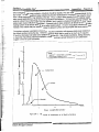
urly variations in total radiation are the result of the Earth's rotation. Early morning sun is at a very low
gle, and solar rays must penetrate a thicker atmospheric layer. Thus, maximum radiation occurs at solar
on when the Sun is at the highest angle, as illustrated by Figure 2A-4.
nal variations of solar radiation are caused by different latitudes as well as weather conditions. Monthly
ons in solar radiation on horizontal surfaces for selected cities in the United States are provided by the
Climatic Data Center, Asheville, North Carolina. The "Solar Radiation Energy Resource Atlas of the
States," SERllSP-642-1037, published by the Solar Energy Research Institute, October 1981, may be
ted for insolation data also.
Section 2 - Feasibility Study
Appendixes - Page 2A-2
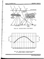
When designing solar energy systems, collectors should be sloped so they are close to perpendicular to the
Sun's rays. To maximize solar energy collection during the heating season, the plane of the collector should
have a slope angle greater than latitude at the site. Thus, a collector slope greater than the latitude angle is
more nearly perpendicular to solar rays from September through March. To maximize summer collection, the
collector should have a slope angle less than latitude, and if collection is desired throughout the year, a slope
angle nearly equal to latitude is appropriate. A general rule is to slope collectors at latitude for a service water
heating system and at latitude pius 15° for a space heating system. (In some evacuated collectors, the tubes
instead of the modules may be rotated to slope the absorber surface and accomplish the same purpose.)
The preferred collector orientation is true south. Any other orientation will decrease total energy incident on
the collector surface during the day. However, deviations either east or west by as much as 30° (equal to
2 hours) will decrease total daily solar radiation by less than 5%. Site climatic conditions, building structure,
or load profile may affect preferred orientation; constant morning overcast followed by sunny afternoons
suggests a west-of-south orientation.
20
• Note:
1 watV(m 2 • micrometer) = 0.008 Btu/(h • ft 2 • in. x 10 -6)
1 micrometer =39.4 x 10 -6 in.
"...
QI
(jj 1 6
E
o
t
.
~
Visible Band
Intrared
~
I
!0U,travio,et
~
1
o LL.---L'_-L:...J...
1
...l
2
......l......=:::::==_
3
Wave length-Micrometers'
Figure 2A-1.
Solar Design Manual
Spectrum of Irradiance at the Earth's Surface
Appendixes - Page 2A-3
Section 2 - Feasibility Study
UPPER ATMOSPHERE
Figure 2A-2.
2000
>:
III
"?
N
e.:i
-
~
1000
Atmospheric Effects on Solar Radiation
······r· I· · · · · ~· · · · · ·~
~
11:1
EARTH
Direct
Radiation
Diffuse Radiation
~_.._" ;'.~: t······T······r····r··········1······
.:
.
........... ~... :
:
:
22,800
I
J .
11,400
o
JAN
FEB
MAR APR MAY JUN
JUL AUG SEP OCT NOV DEC
Figure 2A-3. Monthly Variation of Average Dally Radiation
on a Horizontal Collector In Boulder, Colorado
Solar Design Manual
';:'
---------------------ip
!
Appendixes - Page 2A-4
Section 2 - Feasibility Study
·
··
.............
300
..
..
..
.
...
..
..
..
•••• •• J ••••••••••••• \ ••••••••••
945.0
250
200
..c:
.
.. ..
• • ,
•••••
. ..
-:;-
C'I
ai
··
··
~
••••• '0" ••••• '• •••••• 0° ••
..
.
150
472.5
100
•
·
~
···
·
···
·
..·
..
...
..
...
..
o
50
630.0
·
. ··
·
···
·
··
..
'
4
6
.
..
...
..
.
.
...
...
..
..
..
..
...
. ...
.
.
.
.
..
.
.
.
.
..
.
•
•
.
315.0
• • • • • • • • • • • • • • • • • • • 0.
...
...
..
...
..
..
•
...
..
...
.
..
...
.
•
..
...
..
...
.
..
..
•
..
.
...
.
; ...... ~ .. 157.5
..
..
··
.
.
'.
.
··
.
.
.
....;.._...;.._......;,._ _.. .....;,_.;...._..;.._.....;.......;,_;..._"';'_""":_ _";"''';''',;",;""",jj'0
..;...
5
• • • • • • ' • • • • • • •' 0
7
8
9
"
10
11
12
2
3
4
5
6
Time of Day
Figure 2A-4.
Solar Design Manual
Hourly Record of Total Solar RadIation on a Horizontal Collector
on Clear Days at Fort Collins, Colorado
7
Appendixes - Page 2B-l
Section 2 - Feasibility Study
APPENDIX 28
GUIDELINES FOR USING F-CHART PROGRAM
28.1
Introduction
I
I
r
F-CHART Version 5 is an updated program designed for use on microcomputers to estimate the annual
perlormance of various solar energy systems.
It can be used for the following collector types and application combinations described in the design manual:
Liquid flat plate collectors for service water heating or space
heating or both
liquid evacuated collectors for service water heating or
space heating or both
Air flat plate collectors for space heating with and without hot
water heating.
28.2
Guidelines for Selection of Input Data
F-CHART is used to estimate the thermal perlormance of the proposed solar energy system in the feasibility
study, Section 2.3, and in the perlormance/cost verification, Section 3.9. The following are guidelines for the
required input data for these F-CHART calcu!ations.
28.3
Collector Parameter Sets
Flat Plate Collector
The parameter set for the fJ,Iltpi::JIecoI[Bctor in ;:j liquid cooled system is listed below, as reoroducad from the
program output, along with the default values in I-P and SI units.
2
3
4
5
- 6·····
7
8
9
10
11
12
i3
14
15
NUMBER OF COLLECTOR PANELS
COLLECTOR PANEL AREA
FR*UL (TEST SLOPE)
FR*TAU*ALPHA (TEST INTERCEPT)
COLLECTOR SLOPE
-COLl::ECTOR-AZIMUTH (SOUTH = 0)
INCIDENCE ANGLE MOD TYPE (8-10)
NUMBER OF GLAZINGS
INC ANGLE MODIFIER CONSTANT
INC ANGLE MODIFIER VALUErS)
i ,999 ,998 .995 .981 .953 .882
.7 .35 0
COLLECTOR FLOW RATE/AREA
COLLECTOR FLUID SPECIFIC HEAT
MOD!FY TEST VALUES (i=Y,2=N)
TEST COLLECTOR FLOW RATE/AREA
TEST FLUID SPECIFIC HEAT
Unit
Default (I-P)
Unit
Default (51)
26
26
20.8
.74
FT2
1.93
BTU/HR-FT2-F 4.22
.7
45
o
.7
45
0
DEG
DEG
8
2
DEG
DEG
8
2
0
o
11
1.0
2
11
0.8
M2
W/M2-C
LB/HR-FT2
BTUlLB-F
0.15
4.19
LB/HR-FT2
BTUlL8-F
0.015
3.35
KG/S-M2
KJ/KG-C
2
KG/S-M2
KJ/KG-C
Solar Design Manual
Appendixes - Page 2B-2
Section 2 - Feasibility Study
Evacuated Collector
The parameter set for the evacuated collector in a liquid cooled system is listed below, as reproduced from
the program output, along with the default values in I-P and SI units. Evacuated collectors are modified in the
same manner as flat plate collectors with the exception that incidence angle modifiers may be specified for
the planes parallel and perpendicular to the tube axis.
UnIt
Default (I·P)
1
2
3
4
5
6
7
8
9
10
11
12
13
__.
.".""...._" ".. . ...J.4.__
NUMBER OF COLLECTOR PANELS
COLLECTOR PANEL AREA
FA"UC(iEST SLOPE)
26
20.8
.25
.6
45
0
2
FR*TAU*ALPHA(TEST INTERCEPT)
COLLECTOR SLOPE
COLLECTOR AZIMUlli. (SOUTH = 0)
RECEIVER ORIENT (1=EW,2=NS)
INCIDENCE ANGLE MOD
(PERPENDICULAR)
1 .999 .998 .995 .981 .953 .882
.7 .35 0
INCIDENCE ANGLE MOD
(PARALLEL)
1 .999 .998 .995 .981 .953 .882
.7 .35 0
COLLECTOR FLOW RATE/AREA
11
COLLECTOR FLUID SPECIFIC HEAT 1.0
MODIFY TEST VALUES (1=Y,2=N)
2
TEST COLLECTOR FLOW RATE/AREA11
".Ir::§:LFJ"l,.!IP§P.ECIFIC HEAT
0.8
UnIt
Default (51)
26
FT2
1.93 .. !Jl~L__
BTU/HR-FT2-F 1.40
W/M2-C
.6
DEG
DEG
45
0
2
LB/HR-FT2
BTU/LB-F
0.15
KG/S-M2
4.19
KJ/KG-C
2
0.015 KG/S-M2
3.35_ ...KJlKG"C--.__.
LB/HR-FT2
BTU/LB~E ..
DEG
DEG
2B.3.1 Feasibility Study Input for Collector Parameters
The input data, in I-P units, for the feasibility study are determined as follows for the collector parameter set
(the default values are used only when no specific data are available):
1.
Number of Collectors: Use the actual number selected for conceptual analysis (Section 1). If
not selected, divide total gross collector area by 40 fe.
2.
Collector Panel Area: Use the gross areaof selected collector. If not selec!ed, use 40 ft2.
3.
FR*UL (Test Slope): Use ASHRAE test data of selected collector. If not selected, use the
value for an "average" collector discussed in Section 1.5.1.
4,
FR*TAU*ALPHA (Test Intercept): Use ASHRAE test data of selected collector. If not
selected, use the value for an "average" collector discussed in Section 1.5.1.
5.
Collector Slope: For hot water, use slope = latitude. For space heating with or without hot
water, use latitude plus 150 •
6.
Collector Azimuth: Use default value.
Solar Design Manual
Section 2 • Feasibility Study
Appendixes - Page 2B-3
11 or
10.
Collector Flow Rate: Use ASHRAE test flow rate of selected collector. If tested with water
but design fluid is glycol/water, increase flow so that mcp of design = mcp of test. If collector
not selected, use 17.5 Ib/hr-tt2 (= 0.035 gpmlft2 ) for flat plate and default value for evacuated
collectors.
12 or
11.
Collector Fluid Specific Heat: Use value for selected collector fluid at 130°F if water or glycol,
110°F if air.
13 or
12.
Modify Test Values: Set to 2 (no).
14 or
13.
Test Collector Flow Rate/Area: No input.
15 or
14.
Test Fluid Specific Heat: No input.
For flat plate collectors:
7 and
8.
Incidence Angle Mod Type: Select 8 and input 1 for number of glazings.
9.
Inc Angle Modifier Constant: No input.
10.
Inc Angle Modifier Values: No input.
For evacuated collectors:
($f.
7.
Receiver Orientation: Input 1 or 2 as applicable.
8.
Inc Angle Modifier (Perpendicular): Input applicable value if available. If not, input 1.
9.
Inc Angle Modifier (Parallel): Input applicable value if available. If not, input 1.
_"""~"--;:""''''''''''"''''''''''''d'''O_''''''"'''''~
f
1
. t==..
j
28.3.2 Performance/Cost Verification Input for Collector Parameters
_2~-Bac.14u~~~~:~o:~;p~:%n
(repeat paragraph 28.3.1) using actual design information and replacing delaun
' i W a t e r S I O r a g e System Parameter Set
:::~;.~:~rJ~~o~~~e~y~~~~ parameler set and defauR values appear below, as reproduced from the program
~~t
:i
s.
'~.
$I
;~
I
"I
·jr
J"
·f
!
.'~
...L
Solar Design Manual
Appendixes - Page 2B-4
Section 2 - Feasibility Study
Unit
Default (I·P)
1
2
3
4
5
6
7
8
"~
""""9"""_"_""""
10
11
12
13
14
15
16
17
18
127
CITY CALL NUMBER
WATER STORAGE VOLUME
1000
BUILDING UA (0 FOR DHW ONLY)
520
FUEL (I=EL, 2=NG, 3=OIL, 4=OTHER) 2
70
EFFICIENCY OF FUEL USAGE
DOMESTIC HOT WATER (I=Y, 2=N) 1
DAILY HOT WATER USAGE
80
140
WATER SET TEMPERATURE
68
""EN'IIBONMENT TEMPERATURE
DHW STORAGE TANK SIZE
80
7.6
UA OF AUX stORAGEfANK
2
PIPE HEAT LOSS (I-Y, 2-N)
INLET PIPE UA
5
OUTLET PIPE UA
5
1
RELATIVE LOAD HX SIZE
COLLECTOR-STORAGE HX (I=Y, 2=N)2
11
TANK SIDE FLOW RATE/AREA
HEAT EXCHANGER EFFECTIVENESS 0.5
GALLONS
BTU/HR-F
%
GALLONS
F
F
GALLONS
BTUlHR-F
BTUlHR-F
BTU/HR-F
LB/HR-FT2
Unit
Default (51)
127
3750
275
2
70
1
300
60
_20
300
4
2
2.5
2.5
1
2
0.015
0.5
LITERS
WIC
%
LITERS
C
C ""_~ "
LITERS
W/C
W/C
WiC
KG/S-M2
2B.4.1 Feasibility Study Input for Water Storage System Parameters
The input data, in I-P units, for the feasibility study are determined as follows for the water storage system
parameters (default values are used only when no specific data are available):
1.
City Call Number: Use the number from Appendix A of F-CHART's user's manual for city
nearest solar site.
2.
Water Storage Volume: Calculate volume on basis of 1 gal/112 gross collector area (collector
parameter set). This is the volume of the "main storage tank" of Figures 4.2A and 4.2B of the
User's Manual. (Note: A heat loss term is not required for this version of F-CHART. The
program assumes a tank insulated to R13.5 and a length/diameter ratio of 2.)
3.
Building UA: For service water heating only, input integer O. For space heating with or
without service water heating, input building UA value calculated from data in Checklist 2-2.
4.
Fuel: Input integer corresponding to applicable fuel for main heating load (input does not
affect thermal performance).
5.
Efficiency of Fuel Usage: Input default value (does not affect thermal performance).
6.
Domestic Hot Water: Input integer 1 for service water heating with or without space heating
andCbntinue with Items 7, 8, 9, 10, and 11. Input integer 2 if space heating only and skip
Items 7, 8, 9, la, and 11.
Note: Items 7 through 11 input required only for service water heating with and without space heating.
Solar Design Manual
Section 2 - Feasibility Study
Appendixes - Page 2B-5
7.
Daily Hot Water Usage: Input daily hot water use from hot water load of Section 2.2.3. (This
load has to be converted to an average gal/day usage rate.)
8.
Water Set Temp: Input hot water heater temperature indicated on Checklist 2-5; otherwise,
input 130°F.
9.
Environment Temperature: Input expected mechanical room air temperature or input default
value.
10.
DHW Storage Tank Size: If parameter 3 = 0, input same value as for parameter 2. Other
wise, input the value for the "preheat tank," as shown in Figure 4.2A of the User's Manual.
; 1.
UA of Aux Storage Tank: Input UA for the "service hot water tank" or the ''water heater," as
shown in Figures 4.2A and 4.28 of the User's Manual. (If Item 7 is calculated from fuel usage
data and includes the heat loss from the auxiliary tank, this parameter should be set as small
as possible.)
12.
Pipe Heat Loss: input integer 2 (no).
13.
Inlet Pipe UA: No input.
14.
Outlet Pipe UA: No input.
15.
Relative Load HX Size: Input value of 1.
16.
Collector/Storage HX: Input integer 1 for drainback system with separate drainback tank and
for glycol/water systems. Input integer 2 for recirculation system or drainback system with
combined drainbacklstorage tank.
17.
Tank Side Flow Rate/Area: Input value calculated on basis to provide mcp of storage flow =
1.05 mcp of collector loop flow, where "mc p
" is mass flow rate
x specific heat of the fluid.
.
18.
Heat Exchanger Effectiveness: Input value of 0.60.
28.4.2 Performance/Cost Verification Input for Water Storage System Parameters
F-CHART should be rerun (repeat paragraph 28.4.1) using actual design information and replacing default
values where appropriate.
':}
Solar Design Manual
.,Ji
1IIIIIik?
.,a
_
Appendixes - Page 2B-6
Section 2 - Feasibility Study
2B.5
Pebble Bed Storage System Parameter Set
The parameter set for the pebble bed storage system is listed below, as reproduced from the program output,
along with default values in I-P and SI units.
Unit
Unit
Default (51)
Defau It (I-P)
1
2
3
4
5
.6.
7
8
9
10
11
12
13
14
15
16
127
CITY CALL NUMBER
VOLUME OF PEBBLE BED STORAGE 440
520
BUILDING UA
FUEL (1=EL, 2=NG, 3=OIL, 4=OTHER) 2
70
EFFICIENCY OF FUEL USAGE
.DOMESTIC HOT WATER (1=Y, 2=N) 1
80
DAILY HOT WATER USAGE
140
WATER SET TEMPERATURE
68
ENVIRONM ENT TEMPERATURE
80
DHW STORAGE TANK SIZE
7.6
UA OF AUX STORAGE TANK
2
DUCT LOSSES (1=Y, 2=N)
19
INLET DUCT UA
19
OUTLET DUCT UA
15
PERCENT DUCT LEAK RATE
LEAK LOC (1 = IN, 2 = OUT, 3 = BOTH)3
FT3
BTUlHR-F
%
GALLONS
F
F
GALLONS
BTU/HR-F
BTUlHR-F
BTUlHR-F
0/0
127
12.5
275
2
70
1
300
60
20
300
4
2
10
10
15
3
M3
WIC
0/0
LITERS
C
C
LITERS
WIC
WIC
WIC
0/0
2B.5.1 Feasibility Study Input, in I-P Units, for Pebble Bed Storage System Parameters
1.
City Call Number: Input number from Appendix A of F-CHART's user's manual for city
nearest solar site.
2.
Volume of Pebble Bed Storage: Input value based on 0.75 ft 3/ft 2 of gross collector area.
3.
Building UA: Input estimated UA calculated from data in Checklist 2-2.
4.
Fuel: Input integer corresponding to applicable fuel for main heating load (input does not
affect thermal performance).
5.
Efficiency of Fuel Usage: Input default value (does not affect thermal performance).
6.
Domestic Hot Water: Input integer 1 (yes) if water heating is included. Input integer 2 (no) if
water heating is not included.
7.
Daily Hot Water Usage: Input daily hot water use from Section 2.2.3. (This load has to be
converted to an average gallday usage rate.)
8.
Water Set Temp: Input hot water heater temperature indicated on Checklist 2-5; otherwise,
input 130°F.
9.
Environment Temperature: Input expected mechanical room air temperature. If not known,
input default value.
10.
DHW Storage Tank Size: Input volume of "preheat tank", as shown in Figura 4.1 of the
User's Manual, if known for combined hot water and space heating system. If tank size
unknown, use default value.
Solar Design Manual
Section 2 - Feasibility Study
Appendixes - Page 2B-7
11.
UA of Aux Storage Tank: Input UA for the ''water heater," as shown in Figure 4.1 of the
User's Manual. (If Item 7 is calculated from fuel usage data and includes the heat loss from
the auxiliary tank, this parameter should be set as small as possible.)
12.
Duct Losses: Input integer 2 (no).
13.
Inlet Duct UA: No input.
14.
Outlet Duct UA: No input.
15.
Percent Duct Leak Rate: No input.
16.
Leak Loc: No input.
2B.5.2 Performance/Cost Verification Input for Pebble Bed Storage System
F-CHART should be rerun (repeat paragraph 2B.5.1) using actual design information and replacing default
values where appropriate.
Solar Design Manual
Appendixes - Page 2C-l
Section 2 - Feasibility Study
APPENDIX 2C
CONSTRUCTION COST ESTIMATION METHOD
2C.1
Data Source
The Solar in Federal BUildings Program (SFBP) is a legislated program funded by the DOE and designed to
stimulate the growth and improve the efficiency of the solar industry by constructing commercially applicable
solar energy systems on federal agencies' buildings. Thirteen of these solar energy systems, operating
successfully and considered to be typical applications of solar energy for service hot water heating (SHW),
industrial process heat (IPH), or space heating or space cooling (SH, SC), were selected for intensive per
formance monitoring and detailed cost analysis.
The cost analysis did not use actual costs. To remove any effect of government sponsorship, the analysis
used national average labor and materials costs trom R. S. Means Company publications to estimate the cost
of building each of the 13 solar energy systems for a commercial customer. Other sources of construction
cost data availabltHo the AlE may be used at NE's discretion.
2C.2
Data Reduction
The result of the cost analysis was a series of linear equations relating cost to collector area,* one evaluation
for each of the following categories:
Collectors and thermal storage tanks
Mechanical material that included supports for panel arrays, pipe supports, piping,
pumps, valves, heat exchangers, and miscellaneous construction materials
i'ViecnarlicaiiaoOrnt::t:ut::o 10 instciii Cilio assemble Ilie abo....·e ma~a,ia: a;,;c cOj,duc~ ~:-:G
acceptance test of the completed solar energy system
Crane and operator needed to put the solar collectors and tanks in place, where
applicable
Electrical material that included the instrumentation and controls needed to operate
the solar energy system
Electrical labor needed to install the above electrical material.
For the coJlectorltank category, separate equations for flat plate and evacuated collectors are given. For the
other categories, separate equations are given for SHW, SH, and IPH applications. These equations yield a
"National Average Bare Cost" in 1985 U.S. dollars that must be adjusted to the site and the year of the
proposed construction, and increased by overhead, taxes, etc. These equations are:
1.
Collectors + Thermal Storage Tanks(F,)
a.
Flat plate:
Bare cost = $21,308 + [$9. 13/ft2 x collector area (ft2)J
Limits: 1,000 tf :::; area:::; 23,000 ft2
*Convert square meters to square feet to use these equations (1 m2 = 10.76 ft2).
Solar Design Manual
Section 2 - Feasibility Study
b.
2.
3.
Appendixes - Page 2C-2
Evacuated tubes:
Bare cost = $15,777 + [$22.72Jft2 x collector area (fF)]
Limits: 5,000 ft2:s: area:S: 12,000 ft2
Mechanical Material(MM)
a.
Service hot water (SHW):
Bare cost = $5,337 + [$7.05/ft 2 x collector area (ft2)]
Limits: 1,000 ft2:s: area $ 5,000 ft2
b.
Space Heating:
Bare cost = $22,588 + [$12.95Jft2 x collector area (ft2)]
Limits: 1,000 ft2:s: area $ 12,000 ft2
c.
Industrial Process Heating:
Bare cost = $-9,670 + [$13.43Jft2 x collector area (ft2)]
Limits: 11,000 ft2 $ area $ 23,000 ft2
Electrical Material(EM)
a.
Service hot water (SHW):
Bare cost = $2,432 + [$0. 13/ft2 x collector area (ft2)]
Limits: 1,000 ft2:s: area:s: 5,000 ft2
b.
Space Heating:
Bare cost = $1 ,119 + [$0.99/ft 2 x collector area (ft2)]
Limits: 1,000 ft 2 :S: area:S: 11,000 ft2
c.
Industrial Process Heating:
Bare cost = $6,328 + [$0.01/ft 2 x collector area (ft2)]
...._.... _.."'.Limits: 11,000 ft 2 :S: area $ 23,000 ft2
"'" ~
•
4.
5.
.......
-
Mechanical Labor(M L)
a.
Service hot water (SHW):
Bare cost = $18,662 + [$2.93/ft2 x collector area (ft2)]
Limits: 1,000 ft2 $ area $ 5,000 ft2
b.
Space Heating:
Bare cost = $51,551 + [$6.13/ft2 x collector area (ft2)]
Limits: 1,000 ft2 $ area $ 12,000 ft2
c.
Industrial Process Heating:
Bare cost = $30,493 + [$8.11/ft2 x collector area (fF)]
Limits: 11,000 ft2 $ area $ 23,000 ft2
Electrical Labor(E L)
a.
Service hot water (SHW):
Bare cost = $1,550 + [$0.03/ft 2 x collector area (ft2)]
Limits: 1,000 ft2 $ area $ 5,000 ft2
b.
Space Heating:
Bare cost = $640 + [$0.26/ft2 x collector area (ft2)J
Limits: 1,000 ft2 $ area $ 11,000 ft2
Solar Design Manual
__ •
• .......
_00'
_
. . . _ _ ._
Section 2 • Feasibility Study
c.
6.
2C.3
Appendixes - Page 2C-3
Industrial Process Heating (flat plate):
Bare cost = $3,108 + [$0.01/ft 2 x collector area (ft2)]
Limits: 10,000 ft 2 5 area 5 23,000 ft2
Other (crane + operator){T M}
a.
Flat plate + associated thermal storage tank
Bare cost = $743 + [$0.02lft2 x collector area (ft2)]
Limits: 1,000 ft2 5 area 5 23,000 ft2
b.
Evacuated tubes + associated thermal storage tank
Bare cost = $652 + [$0.08/ft2 x collector area (ft2)]
Limits: 5,000 ft2 5 area 5 12,000 ft2
Cost Estimating Procedure
2C.3.1 Bare Cost
The following general equation is used to determine the "Sare Cost" for any site location, solar energy system
application, type ofcollecto r, and collector area:
where
FM
MM
EM
ML
EL
TM
=
=
=
=
=
Fixed material cost of collectors and thermal storage tanks
"National average" mechanical material cost
"National average" electrical material cost
"National average" mechanical labor cost
"National average" electrical labor cost
"National average" other mechanical cost (used for
crane + operator)
These costs are calclJiatsdirom the equaiions in iha previuus paragraph (2.D.2) fed l:-..~ specific 5C:Q~
energy system application, collector type, and collector area of the proposed project in 1985
US dollars and must be adjusted to the year of proposed construction.
C MM
GEM
=
CML
eEL
elM
=
=
City cost
City cost
City cost
City cost
City cost
index for mechanical material
index for electrical material
index for mechanical labor
index for electrical labor
index for other mechanical
These indexes are obtained from R. S. Means Company publications for the construction year of the
proposed project.
2C.3.2 Specific Cost Factors
The following general equation is used to determine the subtotal cost for the specific site:
where
S
p
W
SS
U
=
=
Sales tax, as applicable
Total personnel taxes IN + SS + U
Worker's compensation
Social Security tax
Unemployment tax
=
Solar Design Manual
{
J
..Itt.~
_
Appendixes -Page2C-4
Section 2 - Feasibility Study
2C.3.3 Miscellaneous Costs
Miscellaneous costs
= Me = C + 0
+ P + BP + LI
Recommended Cost Factors
A
where
=
C
o
P
BP
LI
=
=
Subtotal cost, from
paragraph 2D.3.2
Contingency fee
Overhead
Profit
Bonds and permits
Liability insurance
0.05A
0.10 (A
0.10 (A
0.01 (A
0.01 (A
+ C)
+ C + 0)
+ C + 0 + P)
+ C + 0 + P + BP)
_···---·-Not~:·-rhese·recommended cost factois tor contingency fee, overhead, profjf,-bonas--and-permHs~-andliability
insurance are from the cost analysis. They are believed to be reasonable and are used here as examples.
These percentages can be changed if they are determined to be out of line with the site location and the
general bidding competition.
2C.3.4 Total Cost
Total cost = A + Me ( = 1.3A if recommended cost factors are used)
2C.4
Example
The following is the only required data needed to estimate the cost of a large active solar energy system
using the method described above:
Site location
Solar energy system application: SHW/SH/IPH
Total collector area, ft2 (m 2 ).
This information will be used in the above equations to obtain the bare cost, subtotal cost, miscellaneous
costs, and the total cost of a service water solar energy system at Berkeley, California. using flat plate collec
tors with a total area of 4,000 ft2 (372 m2 ).
BC
=
=
= Bare Cost
$57,800 from Equation 1a
$33,500 from Equation 2a
$3,000 from Equation 3a
$30,000 from Equation 4a
$1,400 from Equation 5a
$800 from Equation 6a
From R. S. Means Company
publication
1.004
1.094
1.584
1.459
1.301
BC = 57,800 + 1.004(33,500) + 1.094(3000) + 1.584(30,000) +
1.459(1,400) + 1.301 (800) = $145,319
A = Subtotal Cost
Solar Design Manual
= Be + S(FM + MM + EM) + P(M L + EL )
Appendixes - Page 2C-S
Section 2 - Feasibility Study
S
p
0.065 from R. S. Means Company publication
W + SS + U = 0.1202 + 0.0705 + 0.01 = 0.2007
A = 145,319 + 0.065(57,800 + 33,500 + 3,000) +
0.2007(30,000 + 1,400) = 157,700
Total cost
2C.5
= 1.3A = 1.3(157,700) = $205,000
General Comments
The City Cost Indexes and other cost data used in this example
are for June 1985. Cost data forthe year for which the estimate is to be made can be
obtained from R. S. Means Company pUblications, or other sources of construction data that
are available to the AlE.
Use of the cost equations for each category is limited to the range
of collector areas given with each equation. These limits may be expanded if additional hard
cost data are available.
Bare cost estimates for a combined SH and SHW system can be
assumed to be only the cost of the space heating system because the additional cost for the
SHW is insignificant.
Solar Design Manual
Appendixes - Page 2D-}
Section 2 - Feasibility Study
APPENDIX 20
SAMPLE
SOLAR ENERGY SYSTEM
DESIGN DESCRIPTION FORMAT
Solar Design Manual
Appendixes - Page 2D-2
Section 2 - Feasibility Study
SAMPLE
SOLAR ENERGY SYSTEM
DESIGN DESCRIPTION FORMAT
(Sheet 1 of 5)
I.
Building Description (Reference attachments 1 through 7)
Building owner/user
Address
Actual building location
_
Local government jurisdiction
Building status: Existing __ New or to be built _ _
To be remodeled __ To be converted
Building AlE name/address
Nearest applicable National Weather Service station
Building construction type"
Building size: ft2/f1oor (m2/f1oor)
_
No.offloors
Type of roof: Flat
Other
_
Building usage
People occupancy: Current __ Normal __ Maximum
Occupancy hours __ to
Solar Design Manual
_
_
Appendixes - Page 2D-3
Section 2 - Feasibility Study
SAMPLE
SOLAR ENERGY SYSTEM
DESIGN DESCRIPTION FORMAT
(Sheet 2 of 5)
Days of occupancy: Weekdays only __ 7 day/week
Other
(describe)
Estimated annual hot water load: Btu x t0 6 (MJ)
Hot water heating fuel: Gas__ Oil __ Electricity __Other
Estimated annual space heating load: Btu x 106 (MJ)
Normal heating season:
to
_
_
Space heating type: __ warm air __ Local warm air
Baseboard radiant __ Other
Spcce he:!t!f\G
Steam boiler
SOlJrc~:
FlJrnace_._
Other
_
_
Hot water h8at8r
_
_
Space heating fuel: Gas __ Oil __ Electricity __ Other
_
Energy conservation measures to be implemented (describe):
Electrical power available: Volt __ Phase
Electrical power margin available: kva
_
_
Solar Design Manual
Section 2· Feasibility Study
Appendixes - Page 2D-4
SAMPLE
SOLAR ENERGY SYSTEM
DESIGN DESCRIPl"ION FORMAT
(Sheet 3 of 5)
.... ···It
.. Solar Systsm Descr!pt!on (Reference Attachments 2 through 12)
A.
Solar application
B.
Solar type
C.
C()!Iector Subsystem
Type
(HW, SH, SH/HW)
(draJnback, antifreeze. recirculation)
(flat plate, evacuated tube)
Approximate size __ in. (mm) x _ _ in. (mm)
Collector loop fluid
(water, antifreeze, air)
No. glazing _ _ (1,2)
Absorber coating
(selective, paint)
···'1VliiiiffiUffiASHRAE test intercept
_
Minimum ASHRAE test negative slope
_
Incident angle modifiers (for evacuated collectors)
Total gross collector area
Collector loop flow rate
Collector slope
Collector orientation
Collector mounting
D.
ft2 (m2)
gpm (Us)
o
above hoi'izontal
(east or west of south)
(roof, ground, wall)
Storage Subsystem
Storage media
Total storage volume
Solar Design Manual
(water, rock, other)
1t3 or gal (m3 or L)
_
Appendixes - Page 2D-5
Section 2 - Feasibility Study
SAMPLE
SOLAR ENERGY SYSTEM
DESIGN DESCRIPTION FORMAT
(Sheet 4 of 5)
D.
Storage SUbsysten'l(contlnlJed}
Storage tank pressurized?
_
Heat exchanger (if used) location
Storage loop flow rate
(external, internal)
gpm or cfm (LIs)
Heat exchanger effectiveness
E.
Solar/Main Heating Interface
Makeup water temperature
OF (OC)
Return water temperature (HW)
of (0C)
Return water temperature (SH)
of (0C)
Return air temperature (SH)
III.
_
OF (0C)
Program Description
Design/construction cost limit: $
_
Design completion (from authorization):
Construction completion (after contract):
Design review required: None __ Conceptual
Preliminary __ Final
days
days
_
_
Design review by: Owner __ Independent __ Associate
Designer liaison during construction bid and place: Yes __ No
Designer liaison during construction: Yes __ No
If yes, scope:
_
_
_
_
Solar Design Manual
-, .. \
Appendixes - Page 2D-6
Section 2 - Feasibility Study
SAMPLE
SOLAR ENERGY SYSTEM
DESIGN DESCRIPTION FORMAT
(Sheet 5 of 5)
IV.
Attachments
1.
Checklist 2~1, Page 2-11 -
2.
Checklist 2-2, Page 2-12 - Building Information
3.
Checklist 2-3, Page 2-16 - Site and Environmental Considerations
4.
Checklist 2-4, Page 2-18 -
Energy Conservation Measures
5.
Checklist 2-5, Page 2-22 -
Service Hot Water Data
6.
Checklist 2-6, Page 2·25 -
Space Heating Load Requirements
7.
Checklist
2~7,
Solar Energy System Goals
Page 2-27 - Construction Cost Estimate Summary
Worksheet 2-1, Page 2-28 from Water Use Data
Est!matp.o SP.rv!ce!-!et-W::!.!er!::.cad ea~c:::Jat:en
9.
Worksheet 2-2, Page 2- 29 - Estimated Load Calculation from Fuel Consumption Data
for Service Hot Water or Space Heating (if applicable)
10.
Optimum example simulation program run
11.
Results of economic evaluation
12.
Sketches - Roof plan/elevation, ground mount plan. and
mechanical room plan/elevation
Solar Design Manual