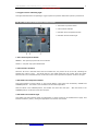
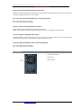
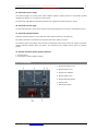
1
‘727 Captain’ FLIGHT MANUAL Part II – Aircraft and Systems
DO NOT USE FOR FLIGHT
‘727 Captain’
FLIGHT MANUAL
PART II – Aircraft and Systems
Captain Sim is not affiliated with any entity mentioned or pictured in this document.
All trademarks are the property of their respective owners.
© 2010 Captain Sim www.captainsim.com
1
‘727 Captain’ FLIGHT MANUAL Part II – Aircraft and Systems
DO NOT USE FOR FLIGHT
2
ABOUT THIS MANUAL
VERSION: 23 FEBRUARY, 2010
WARNING: THIS MANUAL IS DESIGNED FOR MICROSOFT® FSX USE ONLY. DO NOT USE FOR FLIGHT.
The ‘727 Captain’ FLIGHT MANUAL is organized into three Parts.
Each Part is provided as a separate Acrobat® PDF document:
Click START > Programs > Captain Sim > 727 Captain >
•
Part I – User’s Manual
•
Part II – Aircraft and Systems - this document.
•
Part III – Operations
Adobe Acrobat® Reader Required
FOR GENERAL INFORMATION ON THE ‘727 CAPTAIN’ PRODUCT PLEASE USE WWW.CAPTAINSIM.COM .
THIS MANUAL PROVIDES ADDITIONAL INFORMATION ONLY, WHICH IS NOT AVAILABLE ON THE WEB SITE.
© 2010 Captain Sim www.captainsim.com
‘727 Captain’ FLIGHT MANUAL Part II – Aircraft and Systems
DO NOT USE FOR FLIGHT
727-100 PRO PACK FLIGHT MANUAL
PART II –AIRCRAFT SYSTEMS
CONTENTS
Page
5
PANELS LAYOUT
6
LEFT FORWARD PANEL
7
7
8
9
9
10
11
12
14
15
15
16
16
17
18
L01.
L02.
L03.
L04.
L05.
L06.
L07.
L08.
L09.
L10.
L11.
L12.
L13.
L14.
L15.
19
CENTER FORWARD PANEL
20
20
21
21
22
22
23
24
25
26
C01.
C02.
C03.
C04.
C05.
C06.
C07.
C08.
C09.
C10.
27
RIGHT FORWARD PANEL
28
29
R01. LOW PRESSURE ANNUNCIATORS
R06. BRAKE PRESSURE INDICATORS
30
GLARESHIELD PANEL
32
OVERHEAD PANEL
33
34
34
35
36
38
39
40
41
41
42
43
44
O01.
O02.
O03.
O04.
O05.
O06.
O07.
O08.
O09.
O10.
O11.
O12.
O13.
MACHMETER INDICATOR
CLOCKS
AUTOPILOT DISENGAGED WARNING LIGHT
AIRSPEED INDICATOR
RADIO MAGNETIC INDICATOR (RMI)
ANNUNCIATORS
ATTITUDE DIRECTOR INDICATOR (ADI)
HORIZON SITUATION INDICATOR (HSI)
ANNUNCIATORS
STANDBY ALTIMETER
VERTICAL SPEED INDICATOR
PNEUMATIC BRAKE LEVER
RA HEIGHT INDICATOR
ELECTRIC ALTIMETER
DME INDICATOR AND WINDSHEAR AHEAD LIGHTS
LIGHTS TEST/MARKER
ALTITUDE ALERTING PANEL
MARKER LIGHTS
STANDBY ARTIFICIAL HORIZON
ANNUNCIATORS
CONTROLS POSITION INDICATORS
ENGINE INSTRUMENT PANEL
FLAPS INDICATORS /MASTER WARNING
LOW OIL PRESSURE/OIL FILTER BYPASS CAUTION LIGHT
LANDING GEAR CONTROL PANEL
HYDRAULIC POWER SYSTEM
YAW DAMPER SWITCHES
FLIGHT CONTROL WARNING TEST SWITCH
ANTI-SKID CONTROL PANEL
INTERIOR LIGHTING PANEL
EXTERIOR LIGHTING PANEL
STALL WARNING SYSTEM
FLIGHT RECORDER
COMPASS MODE PANEL
FLOOD LIGHT
WINDSHIELD WIPERS AND RAIN REPELLENT PANEL
ENGINE START PANEL
ALTERNATE FLAPS PANEL
© 2010 Captain Sim www.captainsim.com
3
‘727 Captain’ FLIGHT MANUAL Part II – Aircraft and Systems
DO NOT USE FOR FLIGHT
44
45
45
47
48
49
50
O14.
O15.
O17.
O18.
O19.
O20.
O21.
CABIN CALL PANEL
VOICE (TAPE) RECORDER UNIT
WINDOW HEAT PANEL
ANTI-ICE PANEL
WING, ENGINE AND COWL ANTI-ICING PANEL
PITOT STATIC HEAT PANEL
STANDBY MAGNETIC COMPASS
51
AISLE STAND
52
53
54
54
56
57
58
61
61
62
64
65
67
68
P01,P07. ADF CONTROL PANEL
P02,P08. FLIGHT DIRECTOR CONTROLS
P04. RADAR CONTROL PANEL
RADAR OPERATIONAL CONTROLS
THEORY OF OPERATION
PREFLIGHT PROCEDURES
OPERATION IN-FLIGHT - GENERAL
P05. WINDSHEAR FAILURE LIGHT
P06. FLAP POSITION SWITCH
P09. CONTROL STAND
P10,P11. VHF NAV/COMM CONTROL PANEL
P12. AUTOPILOT PANEL
P13. TRANSPONDER/TCAS CONTROL PANEL
P14. AFT PEDESTAL PANEL
69
FLIGHT ENGINEER UPPER PANEL
69
70
71
73
74
75
76
76
77
78
80
U01.
U02.
U03.
U04.
U05.
U06.
U07.
U08.
U09.
U10.
U11.
82
FLIGHT ENGINEER LOWER PANEL
83
85
86
87
88
88
89
90
91
93
94
W01.
W02.
W03.
W04.
W05.
W07.
W08.
W09.
W10.
W11.
W12.
95
SECOND OFFICER’S AUXILIARY PANEL
96
97
97
99
100
P601.
P602.
P603.
P604.
P605.
101
CUSTOMER SUPPORT
DC ELECTRICAL POWER PANEL
ELECTRICAL POWER PANEL
ELECTRICAL POWER PANEL
ELECTRICAL POWER PANEL
OXYGEN PRESSURE PANEL
AFT CABIN ZONE TEMPERATURE CONTROL PANEL
START VALVE OPEN LIGHTS
SMOKE DETECTION SYSTEM PANEL
WING ANTI-ICE AUTO TRIP-OFF AND FIRE WARNING PANEL
PNEUMATIC SYSTEM PANEL
PRESSURIZATION SYSTEM PANEL
FUEL SYSTEM PANEL
CLOCKS
HYDRAULIC BRAKE PANEL
ENGINE OIL PANEL
S/O PANEL LIGHTING CONTROLS
DOOR ANNUNCIATOR PANEL
AUDIO SELECTOR PANEL
FUEL HEAT PANEL
HYDRAULIC PANEL
OXYGEN PANEL
OIL COOLER PANEL
FUEL DUMP PANEL
E.L.T. (EMERGENCY LOCATOR TRANSMITTER)
APU CONTROL PANEL
LEADING EDGE DEVICES ANNUNCIATOR PANEL
ELECTRICAL SYSTEM FAULT ANNUNCIATOR PANEL
© 2010 Captain Sim www.captainsim.com
4
‘727 Captain’ FLIGHT MANUAL Part II – Aircraft and Systems
DO NOT USE FOR FLIGHT
PANELS LAYOUT
© 2010 Captain Sim www.captainsim.com
5
‘727 Captain’ FLIGHT MANUAL Part II – Aircraft and Systems
DO NOT USE FOR FLIGHT
LEFT FORWARD PANEL
L01.
L02.
L03.
L04.
L05.
L03,
L07.
L08.
L10.
L11.
L12.
L13.
L14.
L15.
Machmeter Indicator
Clocks
Autopilot Disengaged Warning Light
Airspeed Indicator
Radio Magnetic Indicator (RMI)
06, 09. Annunciators
Attitude Director Indicator (ADI)
Horizontal Situation Indicator (HSI)
Standby Altimeter
Vertical Speed Indicator
Pneumatic Brake Lever
Height Indicator
Electric Altimeter
DME Indicator and Windshear Ahead Lights
© 2010 Captain Sim www.captainsim.com
6
‘727 Captain’ FLIGHT MANUAL Part II – Aircraft and Systems
DO NOT USE FOR FLIGHT
7
L01. MACHMETER INDICATOR
1 – Mach Pointer
2 - Mach Limitation Mark
The airspeed indicator and the mach meter are separate indicators and they are pitot static operated
(pneumatic). There is no standby mach/airspeed indicator installed when only pneumatic instruments are
installed.
L02. CLOCKS
1. Elapsed Time Hours Minutes Hands
2,4. Hours And Minute Hands
3. Elapsed Time Switch
5. Winding & Setting Control
6. Lower Minute Register Hand
7. Sweep Second Hand
8. Push Button
1. Elapsed Time Hours Minutes Hands
Controlled by elapsed time switch.
2,4. Hours And Minute Hands
Reset by knob on lower lefthand corner of clock
3. Elapsed Time Switch
•
•
•
•
Rotating switch clockwise to
Rotating switch clockwise to
Rotating switch clockwise to
Do not move switch counter
0 resets elapsed time hands to 12 o'clock position.
GO starts elapsed time hands.
STOP stops elapsed time hands.
clockwise from GO to 0 or from 0 to STOP.
5. Winding & Setting Control
Winds clock when turned clockwise.
One complete winding good for 8 days. With knob pulled out, turning in either direction will set main hour
and minute hands.
© 2010 Captain Sim www.captainsim.com
‘727 Captain’ FLIGHT MANUAL Part II – Aircraft and Systems
DO NOT USE FOR FLIGHT
8
6. Lower Minute Register Hand
Controlled by push button.
7. Sweep Second Hand
Controlled by push button on lower right-hand corner of clock.
8. Push Button
With sweep-second hand at the 12 o'clock position:
•
Pushing button once starts the second hand, pushing a second time stops the hand, pushing a third
time resets hand to 12 o'clock position.
•
Minute register hand indicates elapsed time In minutes of sweep second hand.
L03. AUTOPILOT DISENGAGED WARNING LIGHT
1. Autopilot Disengaged Warning Light
A red light (press-to-test and reset) marked AUTOPILOT DISENGAGED is on both the Captain's and the First
Officer's panel. With the autopilot engaged, the lights will come on flashing any time either or both channels
of the autopilot become disengaged for any reason.
Note:
An interchangeable autopilot component may be installed, which will cause the
autopilot disengaged warning lights to illuminate any time power is applied to the
airplane or any time power is switched to airplane power.
The lights can be extinguished by depressing the autopilot disengaged warning light on the Captain's or First
Officer's panel, or by firmly depressing either autopilot release switch on either control wheel.
Note:
If a failure occurs in the elevator (pitch) channel, use the autopilot disengaged
warning light (reset) to extinguish and rearm the lights, and it will not disengage the
operating aileron (roll) channel.
The autopilot warning lights will illuminate steadily when any one of the self-test switches of the control
channel boxes in the lower 43 compartment is not in the off position. The lights cannot be extinguished
except by positioning the switch to OFF.
The lights can be tested by depressing the light on the Captain's or First Officer's panel. The depressed light
will illuminate steadily, while the remaining light will flash. The lights can also be tested by the master test
and dimming switch.
© 2010 Captain Sim www.captainsim.com
‘727 Captain’ FLIGHT MANUAL Part II – Aircraft and Systems
DO NOT USE FOR FLIGHT
9
L04. AIRSPEED INDICATOR
1. VMO Pointer
2. Airspeed Pointer
3. Movable External Reference Marker
4. Cursor Control
5. VMO Mode Selector
1. VMO Pointer
Displays maximum operating airspeed.
2. Airspeed Pointer
Displays indicated airspeed derived from pitot static pressures
4. Cursor Control
Positions cursor on scale to indicate reference airspeed selected.
L05. RADIO MAGNETIC INDICATOR (RMI)
1. Synchronizing Annunciators
2. Synchronizing Knob
3. Compass Warning Flag
4,7. ADF/VOR Selector Knob
5,6. ADF/VOR Pointers
A radio magnetic indicator (RMI) is provided on each pilot's panel to furnish the radio and magnetic bearing
information required for navigation.
The components of each RMI consist of an azimuth card, a lubber line, two ADF/VOR pointers (No. 1 and No.
2), two ADF/VOR switches (No. 1 and No. 2), a synchronizing knob, a synchronizing annunciator and a
compass warning flag.
The compass card rotates in a manner such that the heading of the airplane will always be read under a
fixed reference index (lubber line) at the top of the instrument. Also, fixed indices are provided at 45°, 90°,
135°, 180°, 225°, 270° and 315°.
© 2010 Captain Sim www.captainsim.com
‘727 Captain’ FLIGHT MANUAL Part II – Aircraft and Systems
DO NOT USE FOR FLIGHT
10
The rotating compass card, or azimuth card, is graduated form 0 to 360 degrees clockwise in two degree
increments.
The card is driven by a motor which receives signals from the directional gyro.
3. Compass Warning Flag
A compass warning flag on the lower right-hand corner of the RMI is marked OFF.
The warning flag will appear with loss of electrical power to the compass system, DG not levelling or
underspeed, or excessive heading error signal.
5,6. ADF/VOR Pointers
Pointers indicate ADF and VOR bearing as selected by the ADF/VOR knobs at the bottom of the instrument.
A narrow pointer marked with a dashed line displays bearings from VOR No. 1 or ADF No. 1 as selected by
the switch in the lower left corner of the instrument.
A wide pointer marked with two parallel solid lines displays bearings from VOR No. 2 (or ADF No. 2 if
installed) as selected by the switch in the lower right corner.
L06. ANNUNCIATORS
1. Master Comparator Warning Light (Amber)
2. Pull Up Light/GPWS Test Switch (Red)
3. GC/Cancel Light
1. Master Comparator Warning Light (Amber)
An amber COMPARATOR light on each pilot's panel directs the pilot's attention to the annunciator on the
center console.
2. Pull up Light/GPWS Test Switch (Red)
-
Illuminates flashing to provide visual warning.
Press to test aural and visual warnings. System cannot be tested between 50 and 1000 feet.
© 2010 Captain Sim www.captainsim.com
‘727 Captain’ FLIGHT MANUAL Part II – Aircraft and Systems
DO NOT USE FOR FLIGHT
11
L07. ATTITUDE DIRECTOR INDICATOR (ADI)
1. Flight Director Bar
2. Glide Slope Pointer
3. Glide Slope Warning Flag
4. Bank Indicator
5. Symbolic Airplane
6. Gyro Warning Flag
7. Course Deviation Scale
8. Test Knob
9. Localizer Warning Flag
10. Slip Indicator
2. Glide Slope Pointer
In parallel with pointer on HSI.
OUT OF VIEW – Until localozer frequency selected and the GS signal malfunction.
IN VIEW
– GS receiver power off or fails
− GS receiver fails
− GS signal belowusable level
In parallel with pointer on HSI.
4. Bank Indicator
Airplane bank angle is displayed by an indicator read against a scale at the top of the instrument. The bank
angle scale is marked at 10°, 20°, 30°, 45° and 60° left and right.
5. Symbolic Airplane
Fixed symbol of airplane. Attitude reference when related to horizon.
6. Gyro Warning Flag
IN VIEW
−
−
−
Vertical gyro power is lost
Giro in fast erection cycle
Instrument amplifier power is lost
7. Course Deviation Scale
The course deviation scale, which is always perpendicular to the course bar, indicates the amount the
airplane is displaced from the desired course.
Each dot on the scale represents 5° of displacement on VOR and 1 1/4° of displacement on a localizer.
The point at which the bar aligns with the course arrow indicates no displacement from the selected course.
9. LOC Warning Flag
Covers runway symbol, appears with navigation (LOC) warning flag on HSI for failure indication.
© 2010 Captain Sim www.captainsim.com
‘727 Captain’ FLIGHT MANUAL Part II – Aircraft and Systems
DO NOT USE FOR FLIGHT
12
10. Slip Indicator
A slip indicator, located on the bottom of the flight director indicator, is provided to monitor slip or skid in
turns.
L08. HORIZON SITUATION INDICATOR (HSI)
1. DME Indicator
2. Course Cursor
3. Compass Card and Lubber Line
4. Compass Heading (Warning) Flag
5. Heading Cursor
6. Course Counter
7. Glide Slope Pointer
8. Glide Slope Warning Flag
9. Navigation Warning Flag
10. Course Bar
11. Heading Selector
12. Course Deviation Scale
13. Symbolic Airplane
14. TO\FROM Indicator
15. Course Selector
1. DME Indicator
Indicates slant range in nautical miles to station tuned on corresponding VHF NAV radio.
2. Course Cursor
Indicates course correspond ing to digital readout on course counter. Rotates with card.
3. Compass Card and Lubber Line
Rotating card driven by compass system indicates airplane magnetic heading under lubber line.
4. Compass Heading (Warning) Flag
IN VIEW
Compass system power fails
Signal is unreliable
Compass display is in error.
5. Heading Cursor
Indicates desired heading for flight director and/or autopilot operation
© 2010 Captain Sim www.captainsim.com
‘727 Captain’ FLIGHT MANUAL Part II – Aircraft and Systems
DO NOT USE FOR FLIGHT
13
6. Course Counter
One for each integrated flight system. Digital readout displays course as set by course selector.
7. Glide Slope Pointer
Indicates glide slope location relative to airplane position. In view when localizer frequency is selected. In
parallel with glide slope pointer on ADI.
8. Glide Slope Warning Flag
IN VIEW over glide slope scale and pointer after localizer frequency is tuned when
•
Glide slope power fails
•
Signal is unreliable.
•
In parallel with glide slope warning flag on ADI.
9. Navigation Warning Flag
IN VIEW
•
VHF NAV radio power fails
•
Signal is unreliable.
10. Course Bar
Movable center portion of course cursor represents segment of VOR radial or localizer beam. Relationship of
bar to course deviation scale shows airplane position with respect to selected course.
11. Heading Selector
Rotation of selector adjusts heading cursor on Captain's and First Officer's HSI's. Selects heading for
computed steering commands. Selected heading (Captain's HSU transmitted to autopilot and flight director.
12. Course Deviation Scale
Reference for measuring displacement from selected course (course bar). One dot deviation of course bar
represents approximately 5 degrees on VOR and 1% degrees on localizer.
13. Symbolic Airplane
Represents airplane position relative to the selected course (course bar).
14. TO\FROM Indicator
Indicates direction of VOR station along selected course. OUT OF VIEW in localizer operation. Shown in TO
position.
15. Course Selector
One for each integrated flight system. Rotation adjusts associated course counter, and course cursor to
desired course for VOR or localizer navigation. Course selected for auto pilot on Captain's HSI.
© 2010 Captain Sim www.captainsim.com
‘727 Captain’ FLIGHT MANUAL Part II – Aircraft and Systems
DO NOT USE FOR FLIGHT
14
L09. ANNUNCIATORS
1. MDA light (amber)
Approach Progress Display
2,8. VOR/LOC Annunciator
3,9. Glide Slope Annunciator
6. HDG Annunciator
7. ALT Annunciator
1. MDA light (amber)
The MDA light illuminate when you pass the altitude you have set on the radio alt bug for the MDA (Minimum
Descent Altitude) for the approach.
Approach Progress Display
Annunciators labeled ALT SEL, ALT, HDG, VOR/LOC and GLIDESLOPE are located on each pilot's forward
instrument panel. ALT SEL, VOR/LOC and GLIDESLOPE may illuminate amber or green. ALT and HDG will
only illuminate green.
2,8. VOR/LOC Annunciator
AMBER — System armed in NAV LOC or AUTO G/S modes prior to intercept of VOR radial or localizer beam.
GREEN - Radial or localizer captured.
3,9. Glide Slope Annunciator
AMBER - System armed in AUTO G/S prior to intercept of glide slope.
GREEN
Glide slope captured.
Green when MAN G/S selected.
6. HDG Annunciator
Paralleles green ENG annunciator of HDG SEL switch on autopilot control panel.
GREEN — Autopilot heading select is active.
7. ALT Annunciator
GREEN — Autopilot is operating in altitude hold.
© 2010 Captain Sim www.captainsim.com
‘727 Captain’ FLIGHT MANUAL Part II – Aircraft and Systems
DO NOT USE FOR FLIGHT
15
L10. STANDBY ALTIMETER
An absolute-pressure measuring altimeter is provided as a standby altimeter.
The indicator has a range of -1,000 to 50,000 feet, indicated by a drum and pointer.
1. Digital Display
2. 100-Foot Pointer
3. Barometric Setting Control
4,5. Altimeter Setting Windows
1. Digital Display
Shows altitude in increments of 100 ft.
2. 100-Foot Pointer
Displays attitude in 100 foot Increment (smallest division equals 20 feet). One full rotation of pointer equals
1000 feet.
3. Barometric Setting Control
Rotation of the control adjusts the barometric setting on the inches of mercury (in HG) indicator.
4,5. Altimeter Setting Windows
Can be set in millibars or inches/Hg.
L11. VERTICAL SPEED INDICATOR
1. Vertical Speed Pointer
Two vertical speed indicators are used on the airplane, one located on the Captain's panel and the other on
the First Officer's instrument panel.
Each indicator operates from the airplane static pressure system and provides instantaneous display of
airplane vertical speed in the range of 0 to 6,000 feet per minute, up or down.
These instruments differ from a conventional vertical speed instrument by the addition of two
accelerometers which generate pressure differences whenever there is a change in the normal acceleration
of the airplane.
© 2010 Captain Sim www.captainsim.com
‘727 Captain’ FLIGHT MANUAL Part II – Aircraft and Systems
DO NOT USE FOR FLIGHT
16
L12. PNEUMATIC BRAKE LEVER
1. Pneumatic Brake Lever
The lever has an OFF position and a range marked INCREASE.
In the OFF position, gas pressure is isolated from the transfer tube and the pneumatic brake line is vented to
ambient pressure.
When the lever is in the INCREASE range, metered pneumatic pressure, depending on the position of the
pneumatic brake lever, reaches the transfer tube and applies all main gear brakes simultaneously.
L13. HEIGHT INDICATOR
1. Decision Height Light
2. Altitude Alert Light.
3. Adjustable Altitude Trip Cursor
4. Pointer
5. Flag Display
6. Push-to-Test Button
7. Adjustable Altitude Trip
A low range radio altimeter is provided on each of the pilot's panels. The low range altimeter displays height
above terrain with an altitude pointer moving over a circular scale. The range of the altimeter is from 0 feet
to 2,500 feet.
A decision height (DH) selector is on one comer of the instrument and a decision height cursor is provided on
the periphery of the altimeter. This cursor can be moved about the periphery of the altimeter with the DH
selector, thus selecting the altitude at which a decision height light will illuminate.
A decision height light marked DH is on each pilot's panel and on each radio altimeter. These lights will
illuminate when the altitude pointer on the associated low range radio altimeter reaches the DH cursor on
that altimeter.
The low range altimeter warning flag is a cross-hatched flag which appears on the dial face. When the
altimeter is operating properly, the flag is retracted.| The cross-hatched warning flag appears with power
loss to the instrument, loss of a return radio signal, incorrect altitude tracking and operation above the
altitude range of the equipment. The flag also appears when the low range radio altimeter test switch is
actuated.
A test switch is installed on the altimeter. Operating the test switch will cause the altimeter to indicate 250
+-10 feet and the warning flag to appear.
On some aircraft, pressing the test switch causes the display to indicate 100 feet or 40 feet (as installed).
© 2010 Captain Sim www.captainsim.com
‘727 Captain’ FLIGHT MANUAL Part II – Aircraft and Systems
DO NOT USE FOR FLIGHT
17
L14. ELECTRIC ALTIMETER
The pilot's altimeters are electrically operated. The Captain operates from the #1 air data computer and
furnishes the air data computer with barometer corrections. These corrections are applied to the altitude
signals sent from the air data computer to the altitude alerting system. The First Officer's altimeter operates
from the air data sensor. This altimeter is the secondary altitude source for the АТС transponder.
On some aircraft, a servo /pneumatic altimeter on the Captain's panel is normally driven by the Air Data
System and provides corrected altitude signals to the altitude alert system. The altimeter reverts to
pneumatic operation in the event of power or air data failure. A pneumatic altimeter is provided on the F/O's
panel which operates from the F/O's static system.
An altitude alerting system gives audible and visual indication of approaching an altitude (acquisition) or
departing from an altitude (deviation). In the acquisition mode, an aural signal tone will sound momentarily
and the alert lights will come on when passing through a point approximately 900 feet above or below the
selected altitude. The light will remain on until approximately 300 feet from the selected altitude. In the
deviation mode when departing the selected altitude the aural signal will sound momentarily and the alert
lights will come on at approximately 300 feet above or below the selected altitude. The alert light will remain
on until reset by pressing the alert light. A failure flag will appear in the alert indicator if a failure occurs in
the Captain's altimeter or the alert indicator.
The altitude alerting system may be tested by turning the altitude selector toward the airplane altitude and
then up through more than 900 feet above the airplane altitude. The aural signal sounds momentarily and
the alert light illuminates when the indicator reads 300 feet from the airplane altitude and remains
extinguished until 300 feet from the airplane altitude. When indicator altitude exceeds airplane altitude by
300 feet, the aural signal sounds momentarily and the alert lights illuminate.
1. Failure Warning Flag
2. Reference Altitude Bug
3. 100 Foot Pointer
4. Altitude Numerical Counter
5,6. Altimeter Setting Windows
7. Barometric Setting Control
8. Reference Altitude Bug Selector
2. 100 Foot Pointer
Displays altitude in 100 foot increments. One full rotation of pointer equals 1000 feet.
3. Altitude Numerical Counter
Displays altitude in thousands and hundreds of feet.
4. Failure Warning Flag
In view indicating loss of signals, power or altitude error.
5,6. Altimeter Setting Windows
Can be set in Millibars or inches/Hg.
7. Barometric Setting Control
Rotation of the control adjusts the barometric setting on the inches of mercury (in hg) indicator.
© 2010 Captain Sim www.captainsim.com
‘727 Captain’ FLIGHT MANUAL Part II – Aircraft and Systems
DO NOT USE FOR FLIGHT
8. Reference Altitude Bug Selector
Turn clockwise for higher reference altitude.
L15. DME INDICATOR AND WINDSHEAR AHEAD LIGHTS
1. DME indicator
2,3. Windshear Ahead Lights (Amber)
1. DME indicator
Provides slant range in nautical miles to station tuned.
© 2010 Captain Sim www.captainsim.com
18
‘727 Captain’ FLIGHT MANUAL Part II – Aircraft and Systems
DO NOT USE FOR FLIGHT
CENTER FORWARD PANEL
C01.
C02.
C03.
C04.
C05.
C06.
C07.
C08.
C09.
C10.
Lights Test/Marker
Altitude Alerting Panel
Marker Lights
Standby Artificial Horizon
Annunciators
Controls / Trimmer Position Indicators
Engine Instrument Panel
Flaps Indicators /Master Warning
Low Oil Pressure/Oil Filter Bypass Caution Lights
Landing Gear Control Panel
© 2010 Captain Sim www.captainsim.com
19
‘727 Captain’ FLIGHT MANUAL Part II – Aircraft and Systems
DO NOT USE FOR FLIGHT
20
C01. LIGHTS TEST/MARKER
1. Marker Beacon Sensitivity Switch
2. Master Test and Dimming Switch
C02. ALTITUDE ALERTING PANEL
1. Altitude Alert System OFF Flag
2. Altitude Set Indicator
3. Altitude Set Control
2. Altitude Set Indicator
Indicated selected altitude in 100-foot increments.
3. Altitude Set Control
Used to set selected altitude in altitude indicator.
An altitude alerting system gives audible and visual indication of approaching an altitude (acquisition) or
departing from an altitude (deviation). In the acquisition mode an aural signal tone will sound momentarily
and the alert lights will come on when passing through a point approximately 900 feet above or below the
selected altitude. The light will remain on until approximately 300 feet from the selected altitude. In the
deviation mode when departing the selected altitude the aural signal will sound momentarily and the alert
lights will come on when passing through a point approximately 300 feet above or below the selected
altitude. The alert light will remain on until reset by pressing the alert light.
© 2010 Captain Sim www.captainsim.com
‘727 Captain’ FLIGHT MANUAL Part II – Aircraft and Systems
DO NOT USE FOR FLIGHT
C03. MARKER LIGHTS
1. Airways Light (Clear)
2. Middle Marker Light (Amber)
3. Outer Marker Light (Blue)
1. Airways Light (Clear)
Illuminates steady when over airways beacon or flashing when over airway fan marker beacon (3000 Hz
signal)
2. Middle Marker Light (Amber)
Illuminates flashing when over ILS middle marker beacon (1300 Hz signal)
3. Outer Marker Light (Blue)
Illuminates flashing when over ILS outer marker beacon (400 Hz signal)
C04. STANDBY ARTIFICIAL HORIZON
1. Bank Indicator
2. Symbolic Airplane
3. Pitch Trim and Gyro Caging Control
1. Bank Indicator
Indicates airplane bank angle in degrees
2. Symbolic Airplane
Reference bars provide attitude reference.
3. Pitch Trim and Gyro Caging Control
CONTROL IN - Rotate to adjust airplane symbol
CONTROL OUT - (Momentary) - Erects horizon
© 2010 Captain Sim www.captainsim.com
21
‘727 Captain’ FLIGHT MANUAL Part II – Aircraft and Systems
DO NOT USE FOR FLIGHT
22
C05. ANNUNCIATORS
1. Stabilizer Out of Trim Light
2. Elevator Low Pressure Annunciators
1. Stabilizer Out of Trim Light
A light on the center panel will illuminate when autopilot inputs to the elevator are not trimmed out by the
stabilizer.
2. Elevator Low Pressure Annunciator
Illuminates when system A or В hydraulic pressure to the elevator power unit is low, or the system A or
system В elevator switch is in the OFF position.
C06. CONTROLS POSITION INDICATORS
1, 2, 3. Controls Position Indicator
Show positions of left (2) and right (3) elevators
and upper and lower (1) rudders when airplane
power is on the bus.
© 2010 Captain Sim www.captainsim.com
‘727 Captain’ FLIGHT MANUAL Part II – Aircraft and Systems
DO NOT USE FOR FLIGHT
23
C07. ENGINE INSTRUMENT PANEL
1,2,3. Thrust Reverser Operating Lights
4-6. Engine Pressure Ratio Setting Pointer
7-9. Engine Pressure Ratio Bug
10-12. Engine Pressure Ratio Setting Display
13-15. EPR Bug Setting Knob
16-18. N1 Tachometers
19-21. Engine Exhaust Gas Temperature
Indicators
22-24. N2 Tachometers
25-27. Engine Fuel Flow Indicators
1,2,3. Thrust Reverser Operating Lights
Three amber thrust reverser operating lights marked REVERSER OPERATING. This light illuminates to
indicate that the reverse thrust unit is not locked in the cruise forward thrust position. This light may be
dimmed if required.
Engine Pressure Ratio Indicators
An indication of engine thrust output is shown by three engine pressure ratio indicators on the pilot's center
panel. Engine pressure ratio is defined as the ratio of the turbine discharge total pressure to the engine inlet
total pressure (Pt7/Pt2) and is a parameter of the thrust developed by the engine.
The indicator is used as a primary thrust setting instrument since EPR is directly proportional to thrust. Most
EPR gauges require normal AC from their respective busses.
13-15. Engine Pressure Ratio Setting Knob
A setting knob enables the pilot to set the reference index and the digital indicator to the preselected EPR
value when the knob is pulled out to the manual position.
The EPR set reference index is automatically set by the PDCS unit when the EPR set knob is pushed into the
automatic position.
© 2010 Captain Sim www.captainsim.com
‘727 Captain’ FLIGHT MANUAL Part II – Aircraft and Systems
DO NOT USE FOR FLIGHT
24
16-18. N1 Tachometers
Indicate RPM of the low pressure compressor. Small dial is graduated in 1% increments marked from 0-9.1
Large dial is graduated in 2% increments marked every 10% from 0-100. Tachometer systems are selfgenerating.
19-21. Engine Exhaust Gas Temperature Indicators
Three engine exhaust gas temperature indicators, calibrated in degrees centigrade, indicate temperature of
the exhaust gases of each engine in the turbine exhaust case. On most aircraft these indicators are self
powered. On other aircraft the EGT indicators are of an improved response type and utilize the 115 volt AC
standby bus as a power source.
22-24. N2 Tachometers
Indicate RPM of the high pressure compressor. Small dial is graduated in 1% increments marked from 0-9.
Large dial is graduated 2% increments marked every 10% from 0-100. Tachometer systems are selfgenerating.
25-27. Engine Fuel Flow Indicators
The engine fuel flow indicators provide a visual indication of the fuel consumption rate for each engine.
Power for these indicators is from the 115V AC2 and from the 28V DC2 bus. The indicators are very accurate
up to 6000 pph, with normal fuel flow rate during engine starts of approximately 1000 pph, and 3200 during
cruise.
C08. FLAPS INDICATORS /MASTER WARNING
1. Master Warning Light (Flashing Red)
2,5. Flap Position Indicators
3,4. Leading Edge Flap Lights
1. Master Warning Light (Flashing Red)
On - when essential ac bus not energized.
Push - extinguishes light on center panel. Will not extinguish power failure warning light on third Crewman's
upper panel.
2,5. Flap Position Indicators
Two dual flap position indicators on the pilots' center panel are marked OUTBD and INBD respectively.
© 2010 Captain Sim www.captainsim.com
‘727 Captain’ FLIGHT MANUAL Part II – Aircraft and Systems
DO NOT USE FOR FLIGHT
25
Two needles in each indicator marked L and R indicate corresponding flap positions. White bands indicate
maximum allowable needle deviation at each flap position.
3,4. Leading Edge Flap Lights
AMBER ILLUMINATED
Any leading edge device in transit.
At flap lever position 2, leading edge devices 2, 3, 6 or 7 not extended.
GREEN ILLUMINATED
At flap lever position 2, slats 2 & 3. 6 & 7 fully extended.
At any other flap lever position, all leading edge Haps and slats fully extended.
No Lights All leading edge flaps and slats retracted.
C09. LOW OIL PRESSURE/OIL FILTER BYPASS CAUTION LIGHT
Low Oil Pressure/Oil Filter Bypass Caution
Lights
Three (amber) lights labeled LOW OIL PRESSURE or FILTER BYPASS are on the pilot's center panel. These
lights provide an indication at the pilot's station to supplement the oil pressure indicators at the S/O's panel.
Normally the light should extinguish during engine start.
When this light is illuminated and oil pressure indication normal, a clogging main oil filter should be
suspected. The incident should be reported as an engine discrepancy.
This light illuminates at 35 ± 1 PSI when pressure is decreasing and goes out at 36.5±1 PSI when pressure
is increasing.
© 2010 Captain Sim www.captainsim.com
‘727 Captain’ FLIGHT MANUAL Part II – Aircraft and Systems
DO NOT USE FOR FLIGHT
26
C10. LANDING GEAR CONTROL PANEL
1-7. Landing Gear Lights
8. Landing Gear Lever
1-7. Landing Gear Lights
Three red lights marked L GEAR, N GEAR and R GEAR will illuminate when the corresponding gear is not
locked in the position, as selected by the landing gear lever, or when any engine thrust lever is retarded with
the landing gear.
Three green lights marked L GEAR, N GEAR and R GEAR illuminate when the corresponding gear is down and
locked.
A red warning light will illuminate when any of the main gear doors or forward nose gear doors are not up
and locked.
8. Landing Gear Lever
The landing gear lever is on the pilot's center panel and has UP-OFF-DN positions.
A placard below the lever indicates limit speeds for landing gear extending, retracting and extended.
The landing gear lever operates the hydraulic landing gear selector valve through a control cable
arrangement.
In the UP position, the landing gear lever in addition to retracting the landing gear, also causes retraction of
the tailskid and automatically applies all wheel brakes.
The tailskid will extend when the landing gear lever is in the DN (down) position.
© 2010 Captain Sim www.captainsim.com
‘727 Captain’ FLIGHT MANUAL Part II – Aircraft and Systems
DO NOT USE FOR FLIGHT
RIGHT FORWARD PANEL
.
R01.
R02,
R03.
R04.
R05.
R07.
R08.
R10.
R11.
R12.
R13.
R14.
R15.
Airspeed/Machmeter Indicator
06, 09. Annunciators
Autopilot Disengaged Warning Light
Mach Airspeed Indicator
Radio Magnetic Indicator (RMI)
Attitude Director Indicator (ADI)
Horizontal Situation Indicator (HSI)
Standby Altimeter
Vertical Speed Indicator
Brake Pressure Indicators
Radio Altimeter
Marker Lights
DME/ Windshear
© 2010 Captain Sim www.captainsim.com
27
‘727 Captain’ FLIGHT MANUAL Part II – Aircraft and Systems
DO NOT USE FOR FLIGHT
28
R02. LOW PRESSURE ANNUNCIATORS
1,2. Aileron Low Pressure Annunciators
2,5. Rudder Low Pressure Annunciators
3,6. Elevator Low Pressure Annunciators
1,2. Aileron Low Pressure Annunciators
Two amber annunciators on the First Officer's panel will read AILERON SYSTEM A and AILERON SYSTEM B,
when illuminated.
When system A or В hydraulic pressure to the aileron power unit is low, or the system A or В aileron switch
is in the OFF position, the aileron system A or В low pressure annunciator will illuminate.
2,5. Rudder Low Pressure Annunciators
Two amber annunciators on the First Officer's panel are marked RUDDER SYSTEM A and RUDDER SYSTEM B.
The annunciator marked RUDDER SYSTEM В will illuminate when hydraulic system В power to the upper
rudder is low or switched off, rendering the upper rudder inoperative.
The annunciator marked RUDDER SYSTEM A will illuminate when hydraulic system A power to the lower
rudder is low or switched off.
3,6. Elevator Low Pressure Annunciators
Two amber annunciators on the First Officer's panel display ELEVATOR SYSTEM A and ELEVATOR SYSTEM B
when illuminated.
When system A or В hydraulic pressure to the elevator power unit is low, or the system A or system В
elevator switch is in the OFF position, the corresponding elevator low pressure annunciator will illuminate.
© 2010 Captain Sim www.captainsim.com
‘727 Captain’ FLIGHT MANUAL Part II – Aircraft and Systems
DO NOT USE FOR FLIGHT
29
R12. BRAKE PRESSURE INDICATORS
1. Pneumatic Brake Pressure Indicator
2. Hydraulic Brake Pressure Indicator
1. Pneumatic Brake Pressure Indicator
Normal reading is 1200 PSI nominal.
2. Hydraulic Brake Pressure Indicator
This indicator indicates pressure on the air side of the brake accumulator. The indicator will display
precharge pressure when the brake hydraulic system is depressurized and will display zero, if the precharge
pressure is lost.
When the brake system hydraulic pressure exceeds precharge pressure, the indicator will display brake
system hydraulic pressure.
Normal Precharge - 1000 PSI.
Normal Pressure - 3000 PSI.
Maximum Pressure - 3500 PSI.
© 2010 Captain Sim www.captainsim.com
‘727 Captain’ FLIGHT MANUAL Part II – Aircraft and Systems
DO NOT USE FOR FLIGHT
30
GLARESHIELD PANEL
1. Engine Failure Light
2. Wheel Well Fire Warning Light
3,9. Freon Bottle Discharge Light
4,7,10. Fire Handles
5,8,11. Bottle Discharge Switches
6. Bottle Transfer (Selector) Switch
12. Fire Test Switch
13. Switch Guard
14. Fire Alarm Bell Cutout Switch
15. Detector Test Button
2. Wheel Well Fire Warning Light
A red fire warning light marked WHEEL WELL on the fire control panel will illuminate and the fire alarm bell
will sound continuously when a fire or overheat condition exists in either main wheel. The same light and bell
will also be energized if an overheat condition in the nose wheel well exists.
When the temperature in the area drops below the alarm level, the light and bell will be de-energized. The
bell may also be de-energized immediately, following a fire or overheat signal by operating the fire alarm
bell cutout switch, remote control APU fire warning horn cutout switch or APU fire warning TEST-RESET
switch.
3,9. Freon Bottle Discharge Light
The light will illuminate when the pressure in the respective bottle falls below a рге-determined value, due to
discharge.
4,7,10. Fire Handles
Three engine fire handles (incorporating fire warning lights) marked "1", "2" & "3" are on the fire panel.
Engine fire extinguishing is accomplished by pulling the affected fire handle and depressing the bottle
discharge switch for at least one second.
With the fire handle pulled, the following actions occur:
1. The extinguisher bottle (discharge squib) and the engine fire extinguisher selector valve are armed.
2. The engine fuel shutoff valve will close.
3. The respective wing anti-ice valves (engine #1 or #3), #2 engine cowl valve and the air conditioning
bleed valve will close.
4. The generator field control relay will trip after 5 to 10 seconds time delay. To allow closure of elect
powered valves of associated engine.
5. The hydraulic fluid supply shutoff valve of engine #1 or engine #2 will close.
6. The hydraulic low pressure light circuit for engine #1 or engine #2 are deactivated.
With the engine fire handle pulled out, and the bottle discharge switch depressed, the actual fire
extinguishing process will commence.
5,8,11. Bottle Discharge Switches
A push button type bottle discharge switch is located under each engine fire handle. When a selector handle
is pulled out, depressing the respective discharge switch will fire the cartridge in the selected freon bottle
valve to release freon and open the respective engine selector valve to permit freon to enter the engine
compartment.
© 2010 Captain Sim www.captainsim.com
‘727 Captain’ FLIGHT MANUAL Part II – Aircraft and Systems
DO NOT USE FOR FLIGHT
31
6. Bottle Transfer (Selector) Switch
This switch, marked BOTTLE TRANSFER, is on the fire control panel. The switch controls the routing of the
freon extinguishing agent from the two freon bottles (RH and LH). If it is necessary to discharge the second
freon bottle, this switch must be selected to the opposite position, in which case a new circuit breaker power
source is also selected.
The RH and LH switch positions are associated with the respective RH and LH bottle discharge lights to
provide for positive selection of a second freon bottle.
12. Fire Test Switch
A test switch marked FIRE TEST with FIRE WALLS-ENGS & WHEEL WELLS positions, on the fire control panel,
is provided to test the fire warning system.
A. With the switch in the FIREWALL position, the engine fire warning lights will illuminate and tine fire alarm
bell will ring, normally within 60 seconds. After releasing the test switch, the lights should extinguish within
15 seconds.
B. With the switch in the ENGS & WHEEL WELLS position, the bell will ring and the wheel well fire warning
light will illuminate immediately. Normally within 60 seconds all engine fire warning lights will illuminate.
The fire test switch must be released immediately when all three engine fire warning lights illuminate. The
time delay between the illumination of the wheel wells fire warning light and the 4 engine fire warning lights
is determined by the time necessary to heat the sensor/responder to the warning temperature.
Caution:
When testing the engine or engine firewall fire detection system, minimize duration of
fire test switch operation. The test should be stopped when all engine fire warning lights
illuminate. Test time should not exceed 60 seconds per each test position. On some
aircraft, the response is immediate when tested.
A fault in the system will be indicated by illumination of the amber fault light on the S/O auxiliary panel. A
fault on the В side of the system will be indicated at any time. A fault on the A side is only indicated
immediately after a test of the system.
14. Fire Alarm Bell Cutout Switch
Will silence the bell and horn and will change the flashing red light on the APU remote control panel to a
steady light. The lights will remain illuminated as long as the fire condition exists.
15. Detector Test Button
When pressed, performs a continuity test of the firewall, engine, and the wheel wall fire detectors, and the
detector circuit ground lights.
© 2010 Captain Sim www.captainsim.com
‘727 Captain’ FLIGHT MANUAL Part II – Aircraft and Systems
DO NOT USE FOR FLIGHT
32
OVERHEAD PANEL
O01.
O02.
O03.
O04.
O05.
O06.
O07.
O08.
O09.
O10.
Hydraulic Power System
Yaw Damper Switches
Flight Control Warning Test Switch
Anti-Skid Control Panel
Interior Lighting Panel
Exterior Lighting Panel
Stall Warning System
Flight Recorder
Compass Mode Panel
Flood Light
© 2010 Captain Sim www.captainsim.com
O11.
O12.
O13.
O14.
O15.
O17.
O18.
O19.
O20.
O21.
Windshield Wipers And Rain Repellent Panel
Engine Start Panel
Alternate Flaps Panel
Cabin Call Panel
Voice (Tape) Recorder Unit
Window Heat Panel
Anti-Ice Panel
Wing, Engine and Cowl Anti-Icing Panel
Pitot Static Heat Panel
Standby Magnetic Compass
‘727 Captain’ FLIGHT MANUAL Part II – Aircraft and Systems
DO NOT USE FOR FLIGHT
33
O01. HYDRAULIC POWER SYSTEM
1,3,5,7,9,11,13,15,17. Switch Guard
2,4,10,12.
Switches
Flight
Control
Hydraulic
Shutoff
6. Spoiler Switch (System A)
8. Spoiler Switch (System B)
14,16. Lower Rudder Switches (Standby and
System A)
18. Upper Rudder Switch (System B)
2,4,10,12. Flight Control Hydraulic Shutoff Switches
Shuts off respective hydraulic system pressure to designated flight controls.
6. Spoiler Switch (System A)
OFF - Shuts off system A hydraulic pressure to outboard flight spoilers.
8. Spoiler Switch (System B)
OFF - Shuts off system В hydraulic pressure to inboard flight spoilers.
Two switches on the overheat panel are marked SPOILER, SYS в INBD and SYS A OUTBD. The switches have
ON-OFF positions and are guarded in the ON position. Each switch controls a motor operated hydraulic
shutoff valve.
When a spoiler switch is in the OFF position, hydraulic supply to the corresponding spoilers is shut off.
Hydraulic locks will prevent upward movement of the flight spoilers when normal hydraulic pressure is not
available.
14,16. Lower Rudder Switches (Standby and System A)
Switches and guards ganged together.
Guards up, switches up – shuts off System A hydraulic pressure to lower rudder. Turns on Standby System
Pump.
Two ganged switches on the overhead panel are marked RUDDER SYS A and STANDBY. The switches have
ON—OFF positions.
When the switches are guarded, the system A rudder switch is on and the standby rudder switch is off. In
this position, the standby rudder power unit is functioning as a gust damper.
When the system A rudder switch is in the OFF position, the standby rudder switch is ON and the standby
hydraulic system is operating. A hydraulic transfer valve will engage the standby power unit hydraulically to
operate the lower rudder.
© 2010 Captain Sim www.captainsim.com
‘727 Captain’ FLIGHT MANUAL Part II – Aircraft and Systems
DO NOT USE FOR FLIGHT
34
18. Upper Rudder Switch (System B)
OFF – shuts off system B hydraulic pressure to upper rudder
The system В rudder switch on the overhead panel is marked RUDDER SYS B. The switch has ON-OFF
positions and is guarded to the ON position.
When the switch is in the OFF position, the upper rudder hydraulic supply shutoff valve is closed, which
deactivated the rudder.
O02. YAW DAMPER SWITCHES
1,3. Switch Guard
2,4. Yaw Damper Engage Switches
2,4. Yaw Damper Engage Switches
Two switches on the overhead panel, each with ON-OFF positions, one marked UPPER and the other LOWER,
are used to control the yaw dampers.
O03. FLIGHT CONTROL WARNING TEST SWITCH
1. Flight Control Warning Test Switch
© 2010 Captain Sim www.captainsim.com
‘727 Captain’ FLIGHT MANUAL Part II – Aircraft and Systems
DO NOT USE FOR FLIGHT
35
O04. ANTI-SKID CONTROL PANEL
1. Anti-Skid Test Switch
2. Nose Gear Brake Released Indicator
3. Nose Gear Brake and Anti-Skid Switch
4,6. Switch Guard
5. Main Gear Anti-Skid Switch
7-10. Brake Released Indicator
The anti-skid system prevents wheel skidding by controlling applied brake pressure.
Maximum braking efficiency is obtained when all wheels are in a slight skid or at a maximum rate of
deceleration short of a skidding wheel.
An electronically controlled anti-skid control valve for each main wheel continuously varies individual brake
pressure in response to wheel action.
Maximum braking is produced under any variety of runway condition.
The anti-skid system consists of individual wheel speed sensors, an antiskid control shield and two dual antiskid control valves. The system also includes a test circuit and indicators which allow the system to be
checked for proper operation in flight or on the ground.
1. Anti-Skid Test Switch
This switch on the overhead panel marked ANTI-SKID TEST can be used to test the anti-skid system with or
without the parking brake on. The switch has momentary INBD & NOSE and OUTBD & NOSE positions, and is
spring loaded to the neutral position.
INBOARD & NOSE
Inb and nose indicators – blank.
Outboard indicators – rel.
OUTBOARD & NOSE
Outb & nose indicators blank
Inboard indicators – rel.
An AC signal, similar to the signal generated by a rotating wheel can be introduced by the test switch into
the anti-skid control module. When the wheels are not rotating and the anti-skid system is armed, this
simulated rotation of the wheels selected by the anti-skid test switch will make brakes available on those
wheels. The corresponding brake released indicators will show blanks.
The remaining wheels, not selected by the test switch position will give a wheel not rotating signal to the
control module. The control module interprets this signal as a locked wheel signal as compared to the
simulated wheel rotating signal and gives a full strength release signal to those wheel brakes. The
corresponding indicators will display REL.
In either test position, the anti-skid return valves will open. Hydraulic fluid will bleed to return, if the brakes
are actuated, or the parking brake is on during anti-skid test.
A line connects the system A reservoir at the 2.5 gallon level with the tope of the system В reservoir to
provide system В with pressurization, make up fluid and thermal expansion.
© 2010 Captain Sim www.captainsim.com
‘727 Captain’ FLIGHT MANUAL Part II – Aircraft and Systems
DO NOT USE FOR FLIGHT
36
3. Nose Gear Brake and Anti-Skid Switch
System deactivated.
5. Main Gear Anti-Skid Switch
Turns off anti-skid system. System active only when landing gear lever is down or the nose gear is not
locked up and parking brake is off.
This switch on the overhead panel is marked MAIN GEAR ANTI-SKID and has ON-OFF positions. The switch is
guarded in the ON position.
The main wheel anti-skid protection is deactivated when the switch is in the OFF position.
The main wheel brakes are normally available with this switch in either the ON or the OFF position.
7-10. Brake Released Indicator
In air (gear up) - all blank (system deactivated)
In air (gear down) - all rel
On ground (above 15 kts) – blank.
On ground (below 15 kts) - nose rel, remainder blank
Parking brake on - all blank (system deactivated)
Four brake released indicators are adjacent to the main gear anti-skid switch on the overhead panel. Two of
the indicators are marked LEFT, OUTBD and INBD. The other two are marked RIGHT, INBD and OUTBD.
These indicators normally show blanks.
When a brake is released by the anti-skid system, the corresponding indicator will display REL.
During anti-skid system test, the brake released indicators of the brakes selected by the anti-skid test switch
position will show blanks and the remaining brake released indicators will show REL.
O05. INTERIOR LIGHTING PANEL
1,11. Map Lights Switch
2. Left FWD & Side Panel Lights
3. Center FWD Panel Lights
4. FWD Panel Background Lights
5. FWD Panel Fluor Lights
6. Overhead Panel Lights
7. Control Stand Red Lights
8. Control Stand White Lights
9. Light Override Switch
10. Right Fwd & Side Panel Lights
12. Compass Light
13. Dome Red
14. Dome White
© 2010 Captain Sim www.captainsim.com
‘727 Captain’ FLIGHT MANUAL Part II – Aircraft and Systems
DO NOT USE FOR FLIGHT
37
2. Left FWD & Side Panel Lights
Control integral Instrument illumination on left forward and tide panels. Alto controls panel light for first and
second observers.
3. Center FWD Panel Lights
Control integral instrument illumination on center panel.
4. FWD Panel Background Lights
Control lights located under the light shield.
5. FWD Panel Fluor Lights
Control white fluorescent lights under light shield.
6. Overhead Panel Lights
Control integral instrument Illumination on overhead panel.
7. Control Stand Red Lights
Control red flood lights located in overhead panel for illuminating the control stand.
8. Control Stand White Lights
Control white floodlight» located in overhead panel for illuminating the control stand.
10. Right Fwd & Side Panel Lights
Control integral instrument illumination on the right forward and side panels.
12. Compass Light
Controls light in standby compass.
13. Dome Red
Three pairs of red and white dome lights provide general diffused illumination of the control cabin.
Two pairs of lights are installed on the left and right supports of the overhead panel, and the other pair in
the center of the aft control cabin area.
The variable intensity control for the red lights is by a switch marked DOME RED, on the overhead panel.
14. Dome White
The control for the three white dome lights is by two switches; a switch to the right of the control cabin door
and the other by a switch marked DOME WHITE on the overhead panel. When external AC power is applied
to the airplane, and the external power switch on the S/O upper panel is in the GRD SERVICE position,
power is available to the white dome lights.
© 2010 Captain Sim www.captainsim.com
‘727 Captain’ FLIGHT MANUAL Part II – Aircraft and Systems
DO NOT USE FOR FLIGHT
38
O06. EXTERIOR LIGHTING PANEL
1-4. Landing Lights Switch
5. Taxi Light Switch
6,7. Runway Turnoff Lights Switch
8. Navigation Lights Switch
9. Beacon (Anti-Collision) Lights
10. Wing Illumination Lights
11. Main Wheel Well Lights Switch
1-4. Landing Lights Switch
Landing lights in the fixed inboard wring L.E. and another in each outboard Krueger flap, provides high
intensity lighting for takeoff and landing. Illumination of these lights is controlled by four switches on the
lower edge of the overhead panel marked LANDING, INBOARD L and R and LANDING, OUTBOARD L and R
5. Taxi Light Switch
A taxi light is mounted on the nose wheel strut. The light is controlled by a switch on the lower edge of the
overhead panel marked TAXI with ON--OFF positions,
6,7. Runway Turnoff Lights Switch
A RUNWAY TURNOFF light is adjacent to and inboard of, the inboard fixed landing light.
The lights provide ground roll illumination and are controlled by two switches on the lower edge of the
overhead panel marked RUNWAY TURNOFF L and R with ON--OFF positions.
Note:
Do not illuminate LANDING and/or RUNWAY TURNOFF lights for more than 5 minutes
while stationary on the ground. Allow a 5 minute cooling period before re-illuminating.
8. Navigation Lights Switch
White tip mounted tail lights are installed on the trailing edges of the wing tips to provide a horizontal white
beam aft. These lights are controlled by the navigation light switch, on the overhead panel, marked
NAVIGATION with ON-OFF--ON BAT positions.
Navigation lights, red left and green right, are provided in the outboard edge of each wing.
The lights are controlled by a switch marked NAVIGATION with ON--OFF--ON BAT positions on the overhead
panel.
In the ON position the lights are powered by 28V AC, and in the ON BAT position by 28V DC.
On some aircraft, the ON position of the nav light switch activates the oscillating position lights. The
stationary position lights are on whenever the aircraft is powered.
Note:
The ON position will be used for all flight operations. The ON BAT position induces unacceptable
compass error and therefore will only be used for maintenance ground towing.
© 2010 Captain Sim www.captainsim.com
‘727 Captain’ FLIGHT MANUAL Part II – Aircraft and Systems
DO NOT USE FOR FLIGHT
39
9. Beacon (Anti-Collision) Lights
The beacon lights on the top and bottom of the fuselage, provide high intensity red flashes, as a proximity
warning of the aircraft. Each beacon light consists of two partly silvered lamps covered with a red glass lens.
The lights are controlled by a switch marked Brc\coN, with ON--OFF positions, on the overhead panel.
10. Wing Illumination Lights
Two wing illumination lights are mounted flush with the fuselage and forward of the wing leading edge.
The lights are controlled by a switch on the lower edge of the overhead panel marked WING with ON-OFF
positions.
11. Main Wheel Well Lights Switch
Each main wheel well is illuminated by two clear lights, one on the forward bulkhead and one on the keel
beam near the ceiling. The lights can be controlled by a switch marked WHEEL WELL with NORMAL--ON
positions on the overhead panel.
With the switch in the NORMAL position the wheel well lights are controlled by the switch in each respective
wheel well. When the switch is in the ON position the wheel well lights will be on regardless of the switch
position in the wheel wells.
O07. STALL WARNING SYSTEM
1. Stall Warning Power Failure Light
3. Stall Warning Test Switch
2. Test Indicator
The stall warning system provides a means of alerting the pilots of a flight condition approaching a stall.
When the system is armed and a near stall attitude is sensed, a shaking device on the Captain's control
column makes the control column shake.
The stall warning system components are as follows: an angle of airflow sensor, a flap position transmitter, a
stall warning computer, a control column shaker motor and a landing gear safety (oleo "squat") switch
circuit. An internal heater is provided for the angle of airflow sensor unit for the vane anti-icing.
The landing gear safety (oleo "squat") switch circuit is used for arming the stall warning system. The stall
warning system airflow sensor is anti-iced continuously any time airplane power is on. With external or APU
power connected, the anti-icing system is not operating except when the system is checked momentarily by
the means of the test switch.
The airflow sensor generates an electrical signal in relation to the airplane stall condition. This signal is
compared with the flap position in the stall warning computer. Whenever the angle of airflow sensor signal
exceeds the flap position signal, the computer applies 28V DC power to the control column shaker motor.
1. Stall Warning Power Failure Light
This amber light marked STALL WARNING OFF is on the overhead panel adjacent to the stall warning test
switch. It will illuminate to serve as a warning, any time there is a failure of 115V AC and/or 28V DC power
and/or to indicate vane heater malfunction.
The light will be on also at all times when the airplane is on the ground and external or APU power is on,
providing the stall warning test switch is not in the TEST position.
Power for the light is supplied from the 28V DC battery bus.
© 2010 Captain Sim www.captainsim.com
‘727 Captain’ FLIGHT MANUAL Part II – Aircraft and Systems
DO NOT USE FOR FLIGHT
40
2. Test Indicator
Rotates during test to indicate reliable inputs from stall warning senior and flap position transmitter.
3. Stall Warning Test Switch
Spring loaded to the NORMAL position and locked from the MTR OFF position. Pulling the switch will bypas
the lock.
HTR OFF - Cuts power to the heater for maintenance purposes.
NORMAL - The system including the vane heater is powered when the airplane landing gear safety sensor is
in the air position.
TEST
- With APU or external power:
1. OFF - light extinguishes.
2. Indicator spins
3. Control columns shake.
- With airplane power:
1. OFF light remains extinguished,
2. Indicator spins.
3. Control columns shake.
This switch marked STALL WARNING TEST on the overhead panel, enables pilots to test the system integrity.
When the switch is momentarily held in the TEST position, a signal is sent into the stall warning computer
and makes the pilot's control column shake; at the same time if the system is operating on external or APU
power, the stall warning power failure light will go off, thus indicating proper operation of the vane heater.
Additionally, a spinner will rotate to indicate the flap-to-computer circuitry is intact. When the switch is
momentarily held in the TEST position, a signal is sent into the stall warning computer and makes the pilot's
control column shake; at the same time if the system is operating on external or APU power, the stall
warning power failure light will go off, thus indicating proper operation of the vane heater. Additionally, a
spinner will rotate to indicate the flap-to-computer circuitry is intact.
O08. FLIGHT RECORDER
1. Flight Recorder Light
2. Flight Recorder Test Switch
The purpose of the flight recorder is to provide continuous recording of airspeed, acceleration, altitude, time
and heading. It also receives data from which the time of each radio transmission from aircraft to ground
station can be determined. The recorder is operating any time electrical power is being supplied by the ship's
generators. An underwater beacon is installed to assist in locating the flight recorder under water.
1. Flight Recorder Light
An amber colored light marked OFF is on the overhead panel. When illuminated, the light indicates power
failure to the recorder or that the recording tape is broken.
Extinguished - recorder it operating either automatically or during test.
2. Flight Recorder Test Switch
With this switch, marked TEST, on the overhead panel, actuated, the flight recorder can be operated on
external or APU power as evidenced by an extinguished flight recorder light while the test switch is closed.
If the flight recorder light does not illuminate after the flight recorder test switch has been depressed, it
indicates that the flight recorder tape is satisfactory.
© 2010 Captain Sim www.captainsim.com
‘727 Captain’ FLIGHT MANUAL Part II – Aircraft and Systems
DO NOT USE FOR FLIGHT
O09. COMPASS MODE PANEL
1,3. Switch Guard
2,4. Compass System Switch
O10. FLOOD LIGHT
Flood Light
1. Red
2. White
© 2010 Captain Sim www.captainsim.com
41
‘727 Captain’ FLIGHT MANUAL Part II – Aircraft and Systems
DO NOT USE FOR FLIGHT
42
O11. WINDSHIELD WIPERS AND RAIN REPELLENT PANEL
1,2. Rain Repellent Switches
3. Windshield Wipers Switch
4. Emergency Exit Lights Unarmed Light
5. Switch Guard
6. Emergency Exit Lights Switch
1,2. Rain Repellent Switches
A rain repellent system is provided to be used in conjunction with the windshield wiper system to improve
visibility during heavy rain. When actuated, the system sprays a predetermined amount of repellent solution
on the Captain's or First Officer's No. 1 window, as selected.
The solution is spread on the windows by rain water flowing over the solution and action of the wiper blades.
This provides the windows with a water repellent coating.
Two push button type switches marked RAIN REPELLENT, LEFT, RIGHT are on the overhead panel. Each
switch actuates a solenoid valve, controlled by a time delay circuit, which controls the flow of repellent fluid
to the spray nozzles at the base of each windshield wiper.
The switch must be depressed momentarily for the full measured flow of repellent fluid to be applied. The
switch then must be released to allow the time delay circuit to reset before another application can be
obtained.
Note:
Apply to one windshield at a time. Do not apply to second windshield until residue is
washed off and repellency is established on first windshield.
Rain repellent may be used any time rain intensity requires the use of windshield wipers. When applied in
light rain, a gel or foam may form when the repellent mixes with water.
3. Windshield Wipers Switch
Each pilot's No. 1 window is provided with an 28V DC (DC2 for LI; DC1 for Rl) electric 4-speed windshield
wiper. The two wipers are separate independent systems with a single 6-position (PARK-OFF-LOW-1/2-3/4HIGH) control switch located on the pilot's overhead panel. The PARK position stows the wipers at the
bottom of the windshield, and is spring-loaded to the OFF position. The LOW through HIGH positions select
the speed of the wipers.
4. Emergency Exit Lights Unarmed Light
An amber light marked EMERGENCY EXIT LIGHTS UNARMED on the overhead panel will be on when the
emergency exit lights switch is either in the ON or OFF positions, provided the battery switch is on.
© 2010 Captain Sim www.captainsim.com
‘727 Captain’ FLIGHT MANUAL Part II – Aircraft and Systems
DO NOT USE FOR FLIGHT
43
O12. ENGINE START PANEL
1. Continuous Ignition Switch
2,4,6,8. Switch Guards
3. Engine Access Door Light
5,7,9. Engine Start Switches
1. Continuous Ignition Switch
Provides low energy ignition for conditions requiring continuous ignition, such as icing conditions, or periods
of moderate or greater turbulence.
5,7,9. Engine Start Switches
Three rotary switches marked ENGINE START with GROUND-OFF-IGN 1, IGN 2-FLIGHT positions are on the
overhead panel. With this switch in the GROUND position, power (ВАТТ BUSS) is supplied to open the start
valve. With this switch in the GROUND or FLIGHT position, the 20-joule ignition system is armed. This
system is energized when the engine start lever is advanced out of the CUTOFF position.
The starter rotates the engine until engine sustaining speed is reached (35-40% N2 RPM). At this speed, the
pilot releases the start switch which interrupts electrical power to the starter valve causing it to close,
disengaging the starter. A pressure rise is indicated on the duct pressure gauge confirming starter valve
closure.
Low pressure air from the external air source, crossbleed air from an operating engine, or compressed air
from the auxiliary power unit is used for starter operation.
The access door for the pneumatic ground service connection is on the lower right side of the fuselage
adjacent to the tailskid.
The pneumatic duct pressure indicator, used to check pneumatic manifold pressure available for starting and
to check starter cutout during starts, is on the Second Officer's upper panel.
On some aircraft, the engine start switches on the overhead panel have three positions: GROUND-OFFFLIGHT. They are spring-loaded from the GROUND position to the OFF position, but will remain in FLIGHT, if
selected.
The FLIGHT or GROUND positions arm the high energy dual ignition system. In the GROUND position, in
addition to arming the ignition system, the starter valve is energized and opens allowing the starter to
accelerate the N2 rotor. The FLIGHT position is used for inflight starting, and provides I high energy ignition
without engaging the starter. On some aircraft, a continuous ignition switch provides low energy ignition for
conditions requiring continuous ignition, such as icing conditions, or periods of moderate or greater
turbulence. On the other aircraft, low energy continuous ignition is provided anytime the ignition is in the
FLIGHT position with the start lever in the IDLE position. When the start lever is in the START position high
energy ignition is provided.
See also CENTRAL FORWARD PANEL, P09 CONTROL STAND - Engine start levers
© 2010 Captain Sim www.captainsim.com
‘727 Captain’ FLIGHT MANUAL Part II – Aircraft and Systems
DO NOT USE FOR FLIGHT
44
O13. ALTERNATE FLAPS PANEL
1. Switch Guard
2. Alternate Flap Master Switch
3,4. Alternate Flap Switches
2. Alternate Flap Master Switch
Operates bypass valve for inboard and outboard trailing edge flaps and leading edge flaps and stats. Turns
on Standby System pump. Arms alternate flap switches.
3,4. Alternate Flap Switches
These two switches on the overhead panel are adjacent to the alternate flaps master switch. The switches,
marked INBD and OUTBD, have UP-OFF-DN positions and are spring-loaded from the DN position to the OFF
position.
When either alternate flap switch is in the DN position, the corresponding trailing edge flaps extend
electrically and the leading edge flaps standby drive shutoff valve will open causing all leading edge flaps and
slats to extend.
When the alternate flap switches move from the DN position to the OFF position, the leading edge flaps and
slats will continue to extend, or remain extended, as long as the alternate flaps master switch is in the ON
position. The trailing edge flaps will stop.
When the alternate flap switches are in the UP position, with the leading edge flaps and slats extended and
the alternate flaps master switch in the ON position, the leading edge flaps and slats will remain extended
and the corresponding trailing edge flaps will retract. The leading edge flaps and slats cannot be retracted
using the alternate flap system.
O14. CABIN CALL PANEL
1. No Smoking Switch
2. Fasten Seat Belts Switch
3. Cabin Attendant Call Switch
4. Cabin Attendant Call Light (blue).
5. Ground Crew Call Switch
1. No Smoking Switch
A switch marked NO SMOKING with ON-OFF positions.
© 2010 Captain Sim www.captainsim.com
‘727 Captain’ FLIGHT MANUAL Part II – Aircraft and Systems
DO NOT USE FOR FLIGHT
45
2. Fasten Seat Belts Switch
A switch marked FASTEN SEAT BELTS with ON--OFF positions.
With this switch in the ON position a chord chime will sound .
3. Cabin Attendant Call Switch
When an attendant call button is depressed a two stroke chime will sound.
4. Cabin Attendant Call Light (blue)
Illuminates and single-tone chime sounds in cockpit while captain call switch is pressed at either attendant's
panel.
5. Ground Crew Call Switch
When the ground crew call switch is depressed, the horn will sound to alert the ground crew.
O15. VOICE (TAPE) RECORDER UNIT
1. Voice Recorder Monitor Jack
2. Voice Recorder Indicator
3. Voice Recorder Area Microphone
4. Voice Recorder Test Switch
5. Voice Recorder Bulk Erase Switch
O17. WINDOW HEAT PANEL
1,2,11,13. Window Heat Switches
3,5,7,9. Window Power On Lights
4,6,8,10. Window Overheat Lights
12. Window Heat Test Switch
1,2,11,13. Window Heat Switches
Four window heat switches on the overhead panel are marked WINDOW HEAT L1 and L2-R1 and R2. Each
has ON--OFF/RESET positions.
© 2010 Captain Sim www.captainsim.com
‘727 Captain’ FLIGHT MANUAL Part II – Aircraft and Systems
DO NOT USE FOR FLIGHT
46
In the ON position, the following occurs: Power is available to the respective window's proportional heat
control unit which provides modulated power in building up to and maintaining a window operating
temperature; power is directed to heat the eyebrow windows (No. 4 and No. 5) on the corresponding side
(left or right); and the overheat monitoring relay unit is energized. Power is also applied to the perimeter
heat circuit on the No 1 and No. 2 windows.
In the OFF/RESET position, the heat control system is de-energized, or in the event of an overheat condition,
the overheat light is turned out and the system is reset for operation.
Perimeter heat is applied to the L and R windshields to prevent delamination, and is activated by the L-1 and
R-1 window heat switches. To deactivate the perimeter heaters, pull the associated L or R #4 and #5
eyebrow circuit breakers on the P6-1 panel.
Perimeter heat is currently being incorporated for both the L-2 and R-2 sliding windows. It will be controlled
by the L-2 and R-2 window heat switches.
3,5,7,9. Window Power On Lights
Four lights (green) marked on are adjacent to the window heat switches. Each light will illuminate when
power is available to the respective heat control unit and its output exceed 5 watts.
4,6,8,10. Window Overheat Lights
Four overheat indicating lights (amber) marked OVERHEAT are directly below each power-on light. The
overheat light will illuminate when the heat control unit is directing power to its respective window and the
window temperature is excessive. All lights are push-to-test type.
12. Window Heat Test Switch
A switch on the overheat panel has momentary POWER ON TEST-OVERHEAT TEST and center OFF positions.
Both test positions require the window heat switches to be on.
In POWER ON TEST, the temperature controller's power output is verified to each window (4 green lights).
In OVERHEAT TEST, an overheat condition is simulated, and the overheat circuit's monitoring reliability is
checked (4 amber lights). On old type of controllers, the power on green lights go out immediately upon
illumination of amber overheat lights. With a newer type of controller installed on various aircraft, the power
on green light will remain on for 55 seconds +_ 15 seconds after power is removed. This will occur even
when the overheat trip is operated. In this case, both amber and green lights will be on for a short period of
time until the power on lamp goes out. Apart from this operational differences, both units are physically and
functionally interchangeable.
© 2010 Captain Sim www.captainsim.com
‘727 Captain’ FLIGHT MANUAL Part II – Aircraft and Systems
DO NOT USE FOR FLIGHT
47
O18. ANTI-ICE PANEL
1. Anti-Ice Duct Temperature Indicator
2. Anti-Ice Duct Overheat Light (Amber)
3. Anti-Ice Duct Temperature Selector
1. Anti-Ice Duct Temperature Indicator
Temperature indication as determined by duct temperature selector.
2. Anti-Ice Duct Overheat Light (Amber)
ILLUMINATED •
Excessive temperature in left or right wing anti-ice supply, or duct.
•
Engine 2 cowl duct.
•
Independent of duct temperature selection.
3. Anti-Ice Duct Temperature Selector
Determines source of temperature displayed by duct temp indicator. ENG 1 - Wing anti-ice left supply duct
temperature. ENG 2 - Engine 2 cowl duct temperature. ENG 3 - Wing anti-ice right supply duct temperature.
© 2010 Captain Sim www.captainsim.com
‘727 Captain’ FLIGHT MANUAL Part II – Aircraft and Systems
DO NOT USE FOR FLIGHT
48
O19. WING, ENGINE AND COWL ANTI-ICING PANEL
1,4. Wing Anti-Ice Valve Position Light (Green)
2,3. Wing Anti-Ice Switch
5,7,10. Engine Inlet Anti-Ice Switches
6,8,11. Engine Inlet Anti-Ice Valve Position Lights
(Green)
9. Anti-Ice Valve Position Light Selector
1,4. Wing Anti-Ice Valve Position Light
The lights marked VALVE POS, ENQ 1, ENG 3 are on the overhead panel. The lights will illuminate if the
position of the valves in the anti-ice supply duct are in agreement with the wing anti-ice switch positions,
and the anti-ice valve position light selector is in the wing position.
2,3. Wing Anti-Ice Switch
The switches are spring-loaded to close from the momentary GRD TEST position.
When the switches are in the OPEN position, the respective 13th stage anti-ice bleed valve opens. Thirteenth
stage air flows through an ejector where it draws in, and mixes with, sixth stage air. The mixed air flows
through the respective wing anti-ice shutoff valve, which is also opened by the wing anti-ice switch.
From the wing anti-ice shutoff valve, the heated air is ducted to the wind leading edges.
The landing gear safety switch prevents wing anti-ice operation with the switch in the open position during
ground operation.
5,7,10. Engine Inlet Anti-Ice Switches
These switches marked ENGINE INLET, ENG 1. ENG 2, ENG 3, with OPEN-CLOSE positions. Each switch
controls three bleed air duct shut-off valves for the respective engine (left 8th stage, 13th stage, right 8th
stage). In addition, the switch for #2 engine controls the 6th stage bleed valve.
6,8,11. Engine Inlet Anti-Ice Valve Position Lights (Green).
These lights marked VALVE pos, ENG I, ENG 2, ENG 3. The lights provide a visual check of agreement
between the control valve position and their respective control switch position.
Illuminated - valve position agrees with switch position.
© 2010 Captain Sim www.captainsim.com
‘727 Captain’ FLIGHT MANUAL Part II – Aircraft and Systems
DO NOT USE FOR FLIGHT
49
9. Anti-Ice Valve Position Light Selector
The five position rotary switch is used in conjunction with the lights to check Anti-Ice Valve position.
The switch is marked OFF--L--COWL-R--WING.
1. When in "L" (LEFT) position, the three valve position lights are connected to their respective engines left
8th stage anti-ice valve. If each valve position agrees with its control switch position (either OPEN or
CLOSE), the position lights illuminate.
Should any of the three valves be in a position opposite to its switch, the respective light will be xtinguished.
2. When in "R" (RIGHT) position, the three valve position lights are connected to the three right 8th stage
valves. Again, if each valve position agrees with its control switch, the respective position light illuminates.
3. The COWL position, checks agreement of the three 13th stage valves. In addition, for engine 2, the 6th
stage valve is wired in series with the 13th stage valve-thus the #2 light will not illuminate unless both
valves agree with the control switch position.
4. WING, checks the position of the wing anti-ice valves, in relation to the wing anti-ice switch position.
O20. PITOT STATIC HEAT PANEL
1,3. Pitot Static Ammeters
2. Pitot Static Heat Ammeters Selector
4,6. Pitot Static Heat Switches
5. Heater OFF Light (Amber)
1,3. Pitot Static Ammeters
The two AC ammeters marked LEFT and RIGHT. The ammeters display current drain for corresponding left
and right heating units.
2. Pitot Static Heat Ammeters Selector
This selector marked PITOT STATIC HEAT with S. P, T. PROBE, AUX P--ELEV P positions. The selector is used
in conjunction with the two AC ammeters to compare current drain for corresponding left and right sensor
heaters. The selector is spring-loaded to "P" (PITOT) position.
4,6. Pitot Static Heat Switches
These switches are on the overhead panel. The left switch is marked PITOT STATIC.TEMP PROBE, ELEV
PITOT; and the right switch is marked PITOT STATIC, AUX РГГОТ, ELEV PITOT. Each switch has OFF-ON
positions.
The left switch controls the heating of the left static ports, left pitot, temperature probe and left elevator
pitot. The right switch controls the heating of the right static ports, right pitot, auxiliary pitot and right
elevator pitot. Current for the left pitot heater and the three left static port heaters is supplied from the
essential AC bus to ensure that power is available from any generator.
© 2010 Captain Sim www.captainsim.com
‘727 Captain’ FLIGHT MANUAL Part II – Aircraft and Systems
DO NOT USE FOR FLIGHT
5. Heater OFF Light (Amber)
Illuminated:
- Pitot static heat switch OFF.
- Pitot static heat switch ON and left or right pitot probe heater inoperative.
O21. STANDBY MAGNETIC COMPASS
1. Compas Correction Card
© 2010 Captain Sim www.captainsim.com
50
‘727 Captain’ FLIGHT MANUAL Part II – Aircraft and Systems
DO NOT USE FOR FLIGHT
AISLE STAND
© 2010 Captain Sim www.captainsim.com
51
‘727 Captain’ FLIGHT MANUAL Part II – Aircraft and Systems
DO NOT USE FOR FLIGHT
52
Panels duplicated in 2D are listed in bold font.
P01,P07. ADF Control Panel
P02,P08. Flight Director Controls
P04. Radar Control Panel
P05. Windshear Failure Light
P06. Flap Position Switch
P09. Control Stand
P10,P11. VHF NAV/COMM Control Panel
P12. Autopilot Panel
P13. Transponder/TCAS Control Panel
P14. Aft Pedestal Panel
P01,P07. ADF CONTROL PANEL
1. Loop Control
2. Beat Frequency Oscillator (BFO) Switch
3. Frequency Indicator
4. Tuning Meter
5. Volume Control
6. Volume Control Function Selector
7. Frequency Band Selector
8. Frequency Band Selector Tuning Control
1. Loop Control
Switch has L-R positions, fast or slow. When moved left or right, the phasing in the fixed loop antenna will
be shifted providing the effect of rotating the antenna. Operates only in LOOP function. Used to determine
bearing information by rotating the loop antenna right or left while observing the tuning meter for minimum
deflection at the aural null position
2. Beat Frequency Oscillator (BFO) Switch
OFF
- Undistorted voice reception is possible.
BFO
- Precise tuning is possible when the function selectoris in the ANT position.
The BFO provides a tone for unmodulated (CW) signals.
4. Tuning Meter
Displays relative strength of signal being received. Most desirable reception is achieved by tuning for
maximum needle deflection.
6. Function Selector
OFF
- Power off.
ADF
- Both the sense and loop antennas operate; bearing information is displayed on the RMI's.
© 2010 Captain Sim www.captainsim.com
‘727 Captain’ FLIGHT MANUAL Part II – Aircraft and Systems
DO NOT USE FOR FLIGHT
53
ANT
- Only the sense antenna is used. The receiver is used for reception of audio signals; no bearing information
is displayed.
LOOP
- Determination of bearing to station is made by manual rotation of the loop antenna until aural null, or loss
of signal, occurs. Determined by listening to the signal or observing the tuning meter for minimum needle
deflection. Best position for audio reception during severe precipitation static.
P02,P08. FLIGHT DIRECTOR CONTROLS
1. Pitch Command Control
2. Autopilot Mode Selector
3. Altitude Hold
3. Altitude Hold
Autopilot holds constant airplane altitude if elevator switch engaged. Pitch controller is ineffective. On APPR
AUTO switch trips OFF when glide slope engages.
© 2010 Captain Sim www.captainsim.com
‘727 Captain’ FLIGHT MANUAL Part II – Aircraft and Systems
DO NOT USE FOR FLIGHT
54
P04. RADAR CONTROL PANEL
RADAR OPERATIONAL CONTROLS
1. BRT
Controls brightness of the indicator display (CW rotation for max brightness).
2. Wx
Selects the Wx (weather) mode of operation. "Wx" will appear in the lower left of the display. Wx colors are:
Black for no returns, Green for weak returns, Yellow for moderate returns, Red for heavy returns and
Magenta for intense returns.
3. WxA
Selects the WxA (weather-alert) mode of operation. "WxA" will appear in the lower left of the display. WxA
colors are: Black for no returns, Green for weak returns, Yellow for moderate returns, Red for heavy returns
and Magenta for intense returns. When the WxA mode is selected, magenta areas of storms flash between
magenta and black at a 1 HZ rate.
4,9. RANGE
Clears the display and advances the indicator to the next range. The upper button increases range, the lower
button decreases it. The radar display ranges are: 5, 10, 20, 40, 80, 160, 240, 320. The selected range is
displayed in the upper right corner of the display with the range ring distance displayed along the right edge.
© 2010 Captain Sim www.captainsim.com
‘727 Captain’ FLIGHT MANUAL Part II – Aircraft and Systems
DO NOT USE FOR FLIGHT
55
5. STAB
The On position provides normal stabilization. The Off position disables and the stabilization antenna tilt
angle is controlled by the tilt control only.
6. GAIN
The gain knob adjusts the radar gain from 0 to -20 dB (CCW rotation reduces gain).
7. Radar Mode Selector
Note:
To select mode click the corresponding inscription shown as outlined red on the Weather
Radar panel screenshot above.
ON - Selects the normal condition of operation for
weather detection. The system will transmit after a
60 second warm-up time is completed. The radar
system initializes to the Wx mode, 80 nm.
Note: The 60 second warm up period can be
monitored upon power up of the system. When the
knob is switched directly from OFF to ON mode, the
display will blank. Just before the warm up period is
complete, the screen will turn black for a few
seconds, then the radar will begin transmitting and
the screen will display radar returns. No radar
transmissions occur until the warm up period is
complete.
TEST - The multicolored arc display test pattern is
displayed in this mode of operation. The test pattern
is initialized and sized to fit the 80 nm range and can
also be scaled with the range select buttons. No
radar transmissions occur while TST is selected.
TEST will appear in the lower left of the display.
STBY - Fully energizes the system circuitry but no
radar transmissions occur in the SBY mode of
operation. The antenna is parked at 0 degrees
azimuth and 30 degrees tilt down with the antenna
drive motors locked. SBY will appear in the lower left
of the display.
© 2010 Captain Sim www.captainsim.com
‘727 Captain’ FLIGHT MANUAL Part II – Aircraft and Systems
DO NOT USE FOR FLIGHT
56
OFF - Removes primary power from the radar
indicator, but the radar still has power applied. The
radar will remain active with no radar transmissions
occurring, for up to a maximum time of 30 seconds.
This time delay allows time to park the antenna at 0
degrees azimuth and 30 degrees tilt down.
8. ON Light
10. TILT/STAB
Permits manual adjustment of antenna tilt 15° up or down for best indicator presentation.
The tilt angle is displayed (yellow) in the upper right corner of the display: D = Down, U = Up..
THEORY OF OPERATION
The primary use of this radar is to aid the pilot in avoiding thunderstorms and associated turbulence. Since
each operator normally develops specific operational procedures for use of weather avoidance radar, the
following information is presented for use at the operator's discretion.
Operational techniques for the radar are similar to earlier generation weather avoidance radars. The
proficient operator manages antenna tilt control to achieve best knowledge of storm height, size, and
relative direction of movement.
RADAR PRINCIPLES
Radar is fundamentally a distance measuring system using the principle of radio echoing. The term RADAR is
an acronym for Radio Detecting and Ranging. It is a method for locating targets by using radio waves. The
transmitter generates microwave energy in the form of pulses. These pulses are then transferred to the
antenna where they are focused into a beam by the antenna. The radar beam is much like the beam of
flashlight. The energy is focused and radiated by the antenna in such a way that it is most intense in the
center of the beam with decreasing intensity near the edge. The same antenna is used for both transmitting
and receiving. When a pulse intercepts a target, the energy is reflected as an echo, or return signal, back to
the antenna. From the antenna, the returned signal is transferred to the receiver and processing circuits
located in the receiver transmitter unit. The echoes, or returned signals, are displayed on an indicator.
Radio waves travel at the speed of 300 million meters per second and thus yield nearly instantaneous
information when echoing back. Radar ranging is a two-way process that requires 12.36 micro-seconds for
the radio wave to travel out and back for each nautical mile of target range. As shown in the distance
illustration below, it takes 123.6 micro-seconds for a transmitted pulse of radar energy to travel out and
back from an area of precipitation 10 nautical miles away
WEATHER RADAR PRINCIPLES
Airborne weather avoidance radar, as its name implies, is for avoiding severe weather, not for penetrating it.
Whether to fly into an area of radar echoes depends on echo-intensity, spacing between the echoes, aircraft
capabilities and pilot experience. Remember that weather radar detects only precipitation drops; it does not
detect minute cloud droplets, nor does it detect turbulence. Therefore, the radar provides no assurance of
avoiding instrument weather in clouds and fog. The indicator may be clear between intense echoes; this
© 2010 Captain Sim www.captainsim.com
‘727 Captain’ FLIGHT MANUAL Part II – Aircraft and Systems
DO NOT USE FOR FLIGHT
57
clear area does not necessarily mean it is safe to fly between the storms and maintain visual sighting of
them.
RADAR BEAM ILLUMINATION
Probably the most important aspect of a weather radar is the antenna beam illumination characteristic. To
make a proper interpretation of what you are seeing on the display, you must have an understanding of
what the radar beam "is seeing". The following figure is a side view of the radar beam characteristic with a
storm depicted at a distance that causes the size of the storm to just fill the 3 dB beamwidth. This would be
the typical situation for a storm at approximately 40 nautical miles with a 12 inch diameter antenna. It's
important to understand and visualize this situation, to enhance your understanding of the rest of this
manual.
RADAR REFLECTIVITY
What target will reflect the radar's pulses and thus be displayed on the indicator? Only precipitation will be
detected by an X-band weather radar. Therefore weather radar does not detect clouds, thunderstorms or
turbulence directly. Instead, it detects precipitation which may be associated with dangerous thunderstorms
and turbulence. The best radar reflectors are raindrops and wet snow or hail. The larger the raindrop the
better it reflects. Because large drops in a small concentrated area are characteristic of a severe
thunderstorm, the radar displays the storm as a strong echo. Drop size is the most important factor in high
radar reflectivity.
The radar display has been calibrated to show five levels of target intensity: Black (level 0), Green (level 1),
Yellow (level 2), Red (level 3), and Magenta (level 4).
PREFLIGHT PROCEDURES
The system never transmits in the OFF, SBY or TST modes.
Accomplish the following procedures completely and exactly.
1) Place the radar controls in the following positions:
• Function switch to TST
• Tilt to UP 7 (will be shown on the indicator display, upper right corner).
The test pattern will appear.
2) With the function switch in TST or SBY, taxi to a clear area where there are no people, aircraft, vehicles,
or metallic buildings within approximately 100 yards.
3) Rotate the function switch to ON. The indicator will automatically display in the Wx mode and 80 nm
range. Weather targets will be displayed in green, yellow, red, or magenta. (Note: A 60 second warm up
time period is required before the system will transmit).
4) Press the range-down button to display 40 nm as the maximum range.
5) Press the WxA button and observe that magenta areas (if any) flash.
6) Repeat the manual tilt adjustment, this time between the 0 and down 15 degrees positions.
© 2010 Captain Sim www.captainsim.com
‘727 Captain’ FLIGHT MANUAL Part II – Aircraft and Systems
DO NOT USE FOR FLIGHT
58
7) Return the function switch to TST or SBY before taxiing!
8) When you are ready for weather detection (after takeoff or just before), place the function switch to ON.
OPERATION IN-FLIGHT - GENERAL
It is the purpose of this section to help you become a proficient radar operator as soon as possible. However,
it is realized that proficiency can only improve with usage. It is, therefore, recommended that the operator
become familiar with the operation of the system during fair weather instead of while trying to penetrate a
storm front.
This section concerns itself with a more detailed discussion of some of these controls and how to make the
most efficient use of them.
Note
Your radar is a weather-avoidance device. It should never be used for weatherpenetration. It will help you see and plan avoidance maneuvers around significant weather
encountered during flight.
TILT MANAGEMENT
Effective antenna tilt management is the single, most important key to more informative weather radar
displays. The prime factors must be kept in mind for proper tilt management:
• The center of the radar beam is referenced to the horizon by the aircraft vertical reference system.
• Adjusting the antenna tilt control will cause the center of the radar beam to scan above or below the
plane of the attitude reference system.
When flying at high altitudes, the use of proper tilt management ensures observation of weather targets
without over scanning. For example, a low altitude storm detected on the long range setting may disappear
from the display as it is approached. While it may have dissipated during your approach toward the storm,
don't count on it. It may be that you are directing the radiated energy from the antenna above the storm as
you get closer. Judicious management of the antenna tilt control will avoid over-scanning a weather target.
EARLY DETECTION OF ENROUTE WEATHER
To set the antenna tilt to optimize the radar's ability to quickly identify significant weather, follow these
steps:
1) Select the Wx (weather) mode of operation. Adjust Brightness control as desired.
2) Select the 50 or 80 nm range.
3) Adjust the antenna tilt to watch the strongest returns seen on the display.
TARGET RESOLUTION
The ability of a weather avoidance radar system to resolve and display two or more closely spaced targets is
limited in range by the transmitted pulse width and display range and in azimuth by the antenna beam
width.
RANGE RESOLUTION
The transmitter pulse width in the radar is 4 micro-seconds, yielding a receiver range resolution of
approximately 1/3 nautical mile.
AZIMUTH RESOLUTION
The ability of the radar to resolve adjacent targets in azimuth is a function of the beam width of the antenna
and the range to the target. The diameter of this radiated beam increases as it gets further away from the
aircraft.
Targets separated by a distance less than the beam diameter (at the target distance) will merge and appear
on the indicator as "one."
© 2010 Captain Sim www.captainsim.com
‘727 Captain’ FLIGHT MANUAL Part II – Aircraft and Systems
DO NOT USE FOR FLIGHT
59
PATH PLANNING
Remember to plan a deviation path early. Simply skirting the red or magenta portion of a cell is not enough.
Plan an avoidance path for all weather echoes which appear beyond 100 nautical miles since this indicates
they are quite intense.
The most intense echoes are severe thunderstorms. Remember that hail may fall several miles from the
cloud, and hazardous turbulence may extend as much as 20 nautical miles; therefore, echoes should be
separated by at least 40 nautical miles before you fly between them. As echoes diminish in intensity, you
can reduce the distance by which you avoid them.
PATH PLANNING CONSIDERATIONS
• Avoid cells containing magenta and red areas by at least 20 nautical miles.
• Do not deviate downwind unless absolute necessary. Your chances of encountering severe turbulence and
damaging hail are greatly reduced by selecting the upwind side of the storm
• If looking for a corridor, remember corridors between two cells containing magenta and/or red areas
should be at least 40 nautical miles wide from the outer fringes of the radar echo. The magenta displays
areas of very heavy rainfall and statistically indicates a high probability of hail.
Note:
Do not approach a storm cell containing magenta and red any closer than 20 nautical
miles. Echoes should be separated by at least 40 nautical miles before attempting to fly
between them.
Cells beyond 75 nautical miles are areas of substantial rainfall, do not wait for red or magenta to appear.
Plan and execute evasive action quickly to minimize "doglegging."
© 2010 Captain Sim www.captainsim.com
‘727 Captain’ FLIGHT MANUAL Part II – Aircraft and Systems
DO NOT USE FOR FLIGHT
60
When a complete detour is impractical, penetration of weather patterns may be required. Avoid adjacent
cells by at least 20 nautical miles.
A "Blind Alley" or "Box Canyon" situation can be very dangerous when viewing the short ranges. Periodically
switch to longer-range displays to observe distant conditions. As shown below, the short-range returns show
an obvious corridor between two areas of heavy rainfall but the long-range setting shows a larger area of
heavy rainfall.
© 2010 Captain Sim www.captainsim.com
‘727 Captain’ FLIGHT MANUAL Part II – Aircraft and Systems
DO NOT USE FOR FLIGHT
61
P05. WINDSHEAR FAILURE LIGHT
Windshear Failure Light
Illuminates when significant mailfunction
detected by built-in test equipment.
P06. FLAP POSITION SWITCH
1. Flap Position Switch
2. Switch Guard
© 2010 Captain Sim www.captainsim.com
is
‘727 Captain’ FLIGHT MANUAL Part II – Aircraft and Systems
DO NOT USE FOR FLIGHT
62
P09. CONTROL STAND
1. Speedbrake Lever
2,4,7. Thrust Levers
3,5,7. Reverse Thrust Levers
8. Flap Lever
9,24. Trim Wheel
10,23. Stabilizer Trim Indicator
11. Parking Brake Lever
12,17. Go-Around Switch
13. Parking Brake Warning Light
14,15,16. Engine Start Levers
18. Stabilizer Cruise Trim Switch
19. Stabilizer Trim Light
20. Flap Lever Scale
21,22. Stabilizer Trim Cutout Switches (Main Electric, Autopilot and Cruise)
1. Speedbrake Lever and Scale
A lever on the control stand marked SPEEDBRAKE, can be moved over a scale with 0°, 5°, 10°, 20°, 30° and
40° markings.
A detent is at the 0° position. The lever can be lifted over the 0° detent. Friction holds the speedbrake lever
in any other position on the scale.
© 2010 Captain Sim www.captainsim.com
‘727 Captain’ FLIGHT MANUAL Part II – Aircraft and Systems
DO NOT USE FOR FLIGHT
63
The speedbrake lever positions the spoiler mixer, ratio changer and ground spoiler control valve through a
rod and cable arrangement.
The spoiler mixer positions the flight spoilers according to inputs received from the speedbrake lever and the
roll control system.
2,4,7. Thrust Levers
Control engine forward thrust.
The thrust levers can only be advanced if the reverse thrust levers are down.
3,5,7. Reverse Thrust Levers
Each throttle has an additional handle which is used to actuate the thrust reversers. The reverse thrust lever
pivots about a point near the top of the throttle.
If reverse thrust is required, the throttle must be retarded to IDLE and then the reverse thrust lever must be
pulled up. Further aft movement of the lever will increase reverse thrust.
8. Flap Lever
The lever controls both inboard and outboard flap hydraulic drive units.
Detents are provided at the flap up (0°), 2°, 5°, 15°, 25°, 30° and 40° positions on the flap quadrant
adjacent to the lever.
Gates which interrupt flap lever travel are at the 2° and 25° positions.
10,23. Stabilizer Trim Indicators
A stabilizer trim indicator and pointer adjacent to each manual trim wheel is calibrated to indicate full
stabilizer travel from 2.5 units airplane nose down to 12.5 units airplane nose up.
The main electric trim system will operate the stabilizer from 0.6 units airplane nose up to 12.25 units
airplane nose up.
14,15,16. Engine Start Levers
Three engine start levers with CUTOFF-IDLE detents are on the control stand. This lever operates the
windmill bypass and shutoff valve in the FCU. With this lever in the IDLE detent, fuel if supplied to the
engine. In the CUTOFF detent, all fuel supply to the engine is shut off. With this lever in the IDLE detent and
with the engine start switch in the GROUND or FLIGHT position, the 20-joule ignition system is energized.
The start levers control the main fuel shutoff valves when in the CUTOFF position.
11. Parking Brake Lever
The parking brake lever on the control stand can be set when the brakes are fully applied, to latch the
brakes in the depressed position.
When the parking brake is set, hydraulic return from the main gear antiskid valves will be blocked and the
anti-skid system will be de-energized.
13. Parking Brake Warning Light
This red light on the control stand will illuminate when the parking brake handle is in the SET position.
18. Stabilizer Cruise Trim Switch
This switch is spring-loaded to the center or neutral position.
Manual operation of the switch controls operation of the stabilizer trim actuator by the cruise trim motor.
© 2010 Captain Sim www.captainsim.com
‘727 Captain’ FLIGHT MANUAL Part II – Aircraft and Systems
DO NOT USE FOR FLIGHT
64
When this switch is actuated, the autopilot pitch channel is disengaged and the stabilizer out of trim light will
not operate.
19. Stabilizer Trim Light
An amber light on the control stand will illuminate when the stabilizer main electric trimmotor is operating,
or when the cruise and autopilot trim motor is operated by the stabilizer cruise trim switch
The light will not be on when the autopilot operates the cruise and autopilot trim motor.
20. Flap Lever Scale
All Indicated flap positions are detented.
In addition, flap positions 2 and 25 are gated to interrupt flap lever travel to cross check airspeed with flap
positions.
P10,P11. VHF NAV/COMM CONTROL PANEL
1. NAV Frequency Indicator
2. COMM Frequency Indicator
3,7. NAV Frequency Selector
4. NAV Volume Control
6. DME Override Button
5,9. COMM Frequency Selector
8. COMM Volume Control
1. NAV Frequency Indicator
Displays the frequency selected by the NAV Frequency Selector Knob.
2. COMM Frequency Indicator
Displays the frequency selected by the COMM Frequency Selector Knob.
3,5. NAV Frequency Selector
Selects frequency as shown in NAV frequency window. Rotate outer ring — changes the digits to the left of the
decimal point. Rotate inner knob - changes the digits to the right of the decimal point.
6. DME Override Button
With DME function switch at OVERRIDE position, each system will track a DME signal at an ILS station up to
a maximum of 200 miles.
7,9. COMM Frequency Selector
Selects frequency as shown in COMM frequency window. Rotate outer ring — changes the digits to the left of
the decimal point. Rotate inner knob - changes the digits to the right of the decimal point.
© 2010 Captain Sim www.captainsim.com
‘727 Captain’ FLIGHT MANUAL Part II – Aircraft and Systems
DO NOT USE FOR FLIGHT
65
P12. AUTOPILOT PANEL
1.
2.
3.
4.
5.
6.
7.
Autopilot Mode Selector
Autopilot Turn And Pitch Controller
Autopilot Aileron Switch
Autopilot Elevator Switch
Altitude Hold Switch
Pitch Channel Selector
Heading Select Switch
1. Autopilot Mode Selector
This control with MAN--NAV LOC--AUTO G/S--MAN G/S positions is on the aft electronic panel. The selector
is held magnetically in all positions but MAN. The selector is spring-loaded to the MAN position.
The selector must be in the MAN. position to engage the autopilot.
In the MAN position the autopilot will maintain the magnetic heading and pitch that exists at the time the
autopilot is engaged. If the airplane is in a bank at the time of engagement, the autopilot will level the
wings. Rotating the turn and pitch controller causes the airplane to roll into a turn. When the desired
heading is reached and the controller is centered, the autopilot will maintain the new heading. Altitude hold
will function in this mode.
If the heading select switch (on the autopilot control panel) is engaged, the aircraft will turn to the heading
selected by the heading cursor on the Captain's course indicator. If the turn and pitch controller is turned,
the heading select switch will automatically switch to off.
With the mode selector in NAV LOC, AUTO G/S, or MAN G/S and the heading select switch engaged (HDG
SEL), the autopilot will turn to or retain the heading selected by the heading selector on the Captain's CI
until either the VOR radial or the localizer course selected on the Captain's CI is captured. At that time, the
heading select switch will automatically switch to off.
In the NAV LOC position, the autopilot will maneuver the airplane to capture and track, correcting for wind, a
localizer course or a VOR radial as selected on the course arrow of the Captain's course indicator.
In the AUTO GS position, the autopilot will track a localizer until the glideslope is intercepted; whereupon the
glideslope will be captured and both the localizer and glideslope will be tracked for a COUPLED ILS approach.
Altitude hold will function in this mode until the glideslope is captured.
If MAN G/s is selected some distance from the glideslope, the airplane will pitch down to establish the 700
feet/minute rate of descent, then if the glideslope is above, the airplane will pitch up the maximum amount
to capture the glideslope from below.
2. Autopilot Turn and Pitch Controller
The autopilot turn and pitch controller is on the aft electronic control panel. The controller will rotate to right
or left for right or left bank control and is provided with forward and aft movement for nose down or nose up
pitch control.
The controller provides for turn control when the autopilot is in the MAN position only.
Pitch control is provided when the mode selector is in any position except AUTO G/s or MAN G/s after
glideslope capture.
© 2010 Captain Sim www.captainsim.com
‘727 Captain’ FLIGHT MANUAL Part II – Aircraft and Systems
DO NOT USE FOR FLIGHT
66
When the autopilot altitude hold switch is in the ALT HOLD position, the pitch controller is de-energized.
3. Autopilot Aileron Switch
This switch marked AIL with ENGAGED-DISENGAGED. The switch is spring-loaded to the DISENGAGED
position and will be magnetically held in the ENGAGED position only when the roll axis interlock circuits are
satisfied.
When this switch is in the ENGAGED position, the autopilot will control the airplane about its roll axis from
signals received from the vertical gyro, the autopilot turn and pitch controller or from navigational facilities
as selected by the autopilot mode selector.
Note:
To engage the aileron switch, at least one yaw damper switch must be engaged
4. Autopilot Elevator Switch
A switch marked ELEV with ENGAGED-DISENGAGED positions. This switch, like the autopilot aileron switch,
is spring-loaded to the DISENGAGED position and will be magnetically held in the ENGAGED position only
when the pitch axis interlock circuits are satisfied.
When these circuits are completed and the switch is in the ENGAGED position, the autopilot will control the
airplane about its pitch axis from signals received from the vertical gyro, the autopilot turn and pitch
controller, or from such navigational facilities as selected by the autopilot mode selector.
Note:
To engage the elevator switch, the aileron switch must be engaged.
5. Altitude Hold Switch
The altitude hold switch on the aft electronic control panel has positions marked ALT HOLD-OFF and is
spring-loaded to the OFF position. The switch is magnetically held in the ALT HOLD position.
The magnetic holding circuit will be broken and the switch will revert to the OFF position with the autopilot
elevator switch in the DISENGAGED position.
With the switch in the ALT HOLD position, the autopilot controls the airplane about its pitch axis so as to
maintain a constant barometric altitude as sensed by the air data computer system.
The pitch control function of the autopilot turn and pitch controller is inoperative when the autopilot altitude
hold switch is in the ALT HOLD position.
6. Pitch Channel Selector
This selector is on the aft electronic panel and has a A--B-(INOP) positions. The AB position is deactivated.
With the selector in the "A" position, the pitch channel controls pitch axis by selecting the left transfer valve,
thereby selecting hydraulic system A as the source of power to control elevators.
When the selector is in the "B" position, the above is duplicated using "B" system hydraulics. Autopilot
elevator switch will trip if pitch channel selector is moved.
7. Heading Select Switch
This switch on the aft electronic control panel has a center (OFF) position and a HDG SEL position. It is
either magnetically held in the HDG SEL position or spring-returned to center off.
With the switch in the HDG SEL position, the autopilot is provided with compass system directional
information.
The HDG SEL position may be used in the following modes: MAN, NAV LOC, AUTO G/S and MAN G/S. The
switch will automatically return to the OFF position when the turn control knob is out of detent, or the
localizer or VOR radial selected is captured.
© 2010 Captain Sim www.captainsim.com
‘727 Captain’ FLIGHT MANUAL Part II – Aircraft and Systems
DO NOT USE FOR FLIGHT
67
P13. TRANSPONDER/TCAS CONTROL PANEL
1. Function Selector
2. Power Light
3. ATC Display Window
4. ATC Display Range Selector
5. Altitude Source Selector
6-7,9-10. Code Selector Knobs
8. Ident Pushbutton
11. Relative Altitude Display Limit Selector
1. Function Selector
Selects operating mode.
STBY mode – places transponder and TCAS system to standby.
3. ATC Display Window
Displays Code set by ATC Code Selectors
4. ATC Display Range Selector
Selects display range of TCAS. To cycle through ranges use click zones - plus to cycle to the right and minus
to cycle to the left.
5. Altitude Source Selector
Selects which of the transponders is in use – the other switched to standby.
6-7,9-10. Code Selector Knobs
Rotate to set code on ATC Display Window.
8. Ident Pushbutton
Initiates ident feature for ATC
© 2010 Captain Sim www.captainsim.com
‘727 Captain’ FLIGHT MANUAL Part II – Aircraft and Systems
DO NOT USE FOR FLIGHT
68
P14. AFT PEDESTAL PANEL
1. Radio Panels and Autopilot Lights Control
2. Rudder Trim Wheel and Indicator
3. Horn Cutout Lever
4. Aileron Trim Wheel and Indicator
5. Stabilizer Brake Release Knob
1. Radio Panels and Autopilot Lights Control
Controls intensity for the dial lights on the electronic control panels
2. Rudder Trim Wheel and Indicator
A rudder trim wheel on the control stand moves the rudder feel and centering cam in the vertical fin to
produce rudder trim.
Linkage is through a separate rudder trim cable system. The amount of rudder trim is indicated by a pointer
moving over a scale marked RUDDER TRIM, which is adjacent to the rudder trim wheel.
4. Aileron Trim Wheel and Indicator
Positions the aileron feel and centering spring through a gear and cable system. A pointer on the control
stand indicates TRIM position.
Trim is ineffective in the manual reversion mode.
© 2010 Captain Sim www.captainsim.com
‘727 Captain’ FLIGHT MANUAL Part II – Aircraft and Systems
DO NOT USE FOR FLIGHT
FLIGHT ENGINEER UPPER PANEL
U01. DC Electrical Power Panel
U02,U03,U04. Electrical Power Panel
U05. Oxygen System Panel
U06. Air Conditioning System Panel
U07. Engine Start Valve Indicators
U08. Smoke Detection System Panel
U09. Wing Anti-Ice Auto Trip-Off and Fire Warning Panel
U10. Pneumatic System Panel
U11. Pressurization System Panel
U01. DC ELECTRICAL POWER PANEL
1. DC Voltmeter
2. DC Ammeter
3. DC Meters Selector
4. Switch Guard
5. Battery Switch
1. DC Voltmeter
Indicates DC voltage of selected source.
2. DC Ammeter
Indicates DC voltage of selected source.
© 2010 Captain Sim www.captainsim.com
69
‘727 Captain’ FLIGHT MANUAL Part II – Aircraft and Systems
DO NOT USE FOR FLIGHT
70
3. DC Meters Selector
TR Positions – Indicate transformer-rectifier current and TR bus voltage.
BAT Position – Indicates battery current and voltage when no AC power on airplane. Battery charging shows
positive amps.
5. Battery Switch
ON – Battery serves as a back-up for battery busses.
OFF – Battery isolated from loads except those on hot batter busses, but continues to charge. Trips the APU
(if running).
U02. ELECTRICAL POWER PANEL
1,4,7. Switch Guard
2,5,8. Generator Drive Disconnect Switch
3,6,9. Generator Drive Low Pressure Light (Amber)
10,11. Galley Power Switch
12,13,14. Generator Drive Temperature Switch
15. External Power Switch
16. External Power Connected Light (Clear)
2,5,8. Generator Drive Disconnect Switches
Disconnect drive from engine and trip generator breaker.
3,6,9. Generator Drive Low Pressure Lights (Amber)
Indicate oil pressure in the constant speed drive is below operating limits.
10, 11. Galley Power Switch
ON – Galley power available to galleys as selected.
12, 13, 14. Generator Drive Temperature Switch
RISE – Indicate oil temperature increase through generator drive.
IN – Indicate temperature of oil at in-put.
© 2010 Captain Sim www.captainsim.com
‘727 Captain’ FLIGHT MANUAL Part II – Aircraft and Systems
DO NOT USE FOR FLIGHT
71
15. External Power Switch
ON – External power on the bus tie. When external power is connected, the generator breakers and APU
generator breaker automatically trips for overvoltage or phase unbalance faults.
OFF – If external power connected, external power DC bus, battery transfer bus, and external power 115V
AC bus powered.
GND SERVICE – 115V AC transfer bus also powered.
16. External Power Connected Light (Clear)
ON – Ground power available at external power connection.
U03. ELECTRICAL POWER PANEL
1,10,19. Generator Drive Oil Temperature
Indicator
2,11,21. Bus Tie Breaker Light (Amber)
3,12,20. Bus Tie Breaker Switch
4,13,23. Generator Breaker Light (Amber)
5,14,22. Generator Breaker Switch
6,15,25. Generator Field Light (Amber)
7,16,24. Generator Field Switch
8,17,26. Power Meter
9,18,27. Frequency Control Knob
2,11,21. Bus Tie Breaker Lights (Amber)
ON – Bus tie breaker open and generator operating isolated.
3,12,20. Bus Tie Breaker Switches
Open circuit between respective A.C. bus and bus tie. Automatically trips due to excitation faults or overload
if respective generator breaker is closed. A phase unbalance on the bus tie will trip all bus tie breakers.
4,13,23. Generator Breaker Lights (Amber)
ON – Generator breaker open and generator disconnected from load bus.
© 2010 Captain Sim www.captainsim.com
‘727 Captain’ FLIGHT MANUAL Part II – Aircraft and Systems
DO NOT USE FOR FLIGHT
72
5,14,22. Generator Breaker Switches
Open circuit between respective generator and A.C. bus. Automatically trips due to generator drive speed
faults, if the drive is disconnected, or if the generator field is off. Trips on engine shutdown. Closing a
generator breaker trips the external power contactor or the APU generator breaker.
6,15,25. Generator Field Lights (Amber)
ON – Generator field relay open, and generator field deenergized. Generator electrically inoperative and
essential power not available from this source.
7,16,24. Generator Field Switches
Turn off generator field. Automatically trips due to generator voltage faults, generator overload, or if engine
fire switch pulled.
8,17,26. Power Meters
Indicates generator real (KW) or reactive (KVAR) load. Indication is controlled by KVARS switch on U04
ELECTRICAL POWER PANEL.
9,18,27. Frequency Control Knobs
Permits frequency adjustment of an isolated generator.
© 2010 Captain Sim www.captainsim.com
‘727 Captain’ FLIGHT MANUAL Part II – Aircraft and Systems
DO NOT USE FOR FLIGHT
73
U04. ELECTRICAL POWER PANEL
1. Essential Power Selector
2. Essential Power Failure Warning Light (Red)
3. Residual Volts Switch
4. AC Voltmeter
5. Frequency Indicator
6. KVARS Switch
7,8. Synchronizing Lights (Clear)
9. AC Meters Selector
1. Essential Power Selector
Selects power source for essential AC bus. If no fault exists, a generator can supply essential power with the
generator breaker tripped. Neither external power nor the APU can supply essential power unless it is on the
sync bus and the #3 bus tie breaker is closed. In standby position, required flight instruments and radios are
powered from battery bus and static inverter.
2. Essential Power Failure Warning Light (Red)
ON – loss of essential power. Master warning light also illuminates.
3. Residual Volts Switch
Changes voltmeter scale from 150 to 30 volts. Indicates residual generator voltage to check rotation and
proper functioning.
4. AC Voltmeter
Indicates voltage as selected.
5. Frequency Indicator
Indicates frequency as selected.
© 2010 Captain Sim www.captainsim.com
‘727 Captain’ FLIGHT MANUAL Part II – Aircraft and Systems
DO NOT USE FOR FLIGHT
74
6. KVARS Switch
Changes U03 ELECTRICAL SYSTEM PANEL Power Meters indication from real (KW) to reactive (KVAR) load
display.
7,8. Synchronizing Lights (Clear)
Connected between the bus tie and the position of the AC meters selector. Blink rate is proportional to
frequency differences.
9. AC Meters Selector
Selects source of AC power to be monitored on AC voltmeter and frequency indicator.
U05. OXYGEN PRESSURE PANEL
1. Flight Crew Oxygen Pressure Indicator
2. Passenger Oxygen Pressure Indicator
3. Passenger Oxygen Switch
4. Oxygen Pressure Indicating Light
1. Flight Crew Oxygen Pressure Indicator
This indicator marked OXYGEN SYSTEM, CREW is on the Second Officer's upper panel. The indicator is
scaled 0-20 (0-2000 PSI) and indicates pressure in the cylinder and/or line. The pressure transmitter for
this indicator is located downstream of the oxygen cylinder shutoff valve and is common to the indicator on
the external charging panel.
Electrical power is necessary for proper indication.
2. Passenger Oxygen Pressure Indicator
This indicator marked OXYGEN SYSTEM, PASSENGER is on the Second Officer's upper panel. The indicator
is scaled 0-20 (0-2000 PSI) and indicates pressure in the cylinders.
The pressure transducer for this
indicator is common to the indicator on the external charging panel.
3. Passenger Oxygen Switch
The passenger oxygen switch marked OXYGEN SYSTEM, with ON-NORMAL positions, is on the Second
Officer's upper panel and is lockwired to the NORMAL position. This switch when placed in the ON position,
supplies power to the solenoid which operates the electro-pneumatic unit and actuates the passenger
oxygen system. This switch may be used at the discretion of the flight crew or in the event that both
automatic valves fail to open during an emergency.
© 2010 Captain Sim www.captainsim.com
‘727 Captain’ FLIGHT MANUAL Part II – Aircraft and Systems
DO NOT USE FOR FLIGHT
75
4. Oxygen Pressure Indicating Light
This light illuminates when the passenger oxygen system low pressure distribution system is pressurized.
U06. AFT CABIN ZONE TEMPERATURE CONTROL PANEL
1. Auto Pack Trip Cutout Switch
2. Valve Position Indicator
3. Aft Cabin Zone Temperature Switch
4. Aft Cabin Zone Overheat Light
1. Auto Pack Trip Cutout Switch
NORMAL - auto pack trip system will arm for takeoff.
CUTOUT - auto pack trip system deactivated.
2. Valve Position Indicator
When the aft zone is selected cooler than the forward zone, the pointer will be to the left, indicating the
forward zone control is open. The pointer will be in the middle when both zone control valves are closed.
When the aft zone is selected warmer, the aft zone control valve opens and the pointer will be to the right.
3. Aft Cabin Zone Temperature Switch
This spring-loaded to neutral switch on the Second Officer's upper panel has momentary COOLER and
WARMER positions. The switch is used to balance the aft cabin temperature.
With the switch in the COOLER position, the forward zone heat valve will open.
WARMER position, the aft zone heat valve will open.
With the switch in the
4. Aft Cabin Zone Overheat Light
This amber light will illuminate when the temperature in either forward or aft conditioned air supply duct
becomes excessive (190°C), driving the appropriate zone control valve closed.
© 2010 Captain Sim www.captainsim.com
‘727 Captain’ FLIGHT MANUAL Part II – Aircraft and Systems
DO NOT USE FOR FLIGHT
76
U07. START VALVE OPEN LIGHTS
1-3. Start Valve Open Lights (amber)
1-3. Start Valve Open Lights (amber)
An engine START VALVE OPEN light is on the Second Officer's lower panel directly above the door
annunciator panel.
The purpose of the light is to provide the flight crew with indication of start valve position.
The three (3) lights are connected individually to each start valve. The appropriate light will be illuminated
when the start valve is open.
A placard under each light states START VALVE OPEN.
U08. SMOKE DETECTION SYSTEM PANEL
1-7. Smoke Detection System
8,9. Secondary Main
Indicator Lights (green)
© 2010 Captain Sim www.captainsim.com
Landing
Gear
Position
‘727 Captain’ FLIGHT MANUAL Part II – Aircraft and Systems
DO NOT USE FOR FLIGHT
77
U09. WING ANTI-ICE AUTO TRIP-OFF AND FIRE WARNING PANEL
1-3. Strut and Lower Aft Body Overheat Lights
4. Wing Anti-Ice Auto Trip-Off Switch
5. Wing Anti-Ice Auto Trip-Off Light (Amber)
6. Overheat Test Switch
1-3. Strut and Lower Aft Body Overheat Lights
Three amber lights will illuminate when overheat conditions exceeding approximately 204°С in the strut, or
124°С in a keel beams area and lower aft section (aft cargo and rear entry stairs), are detected.
4. Wing Anti-Ice Auto Trip-Off Switch
Since a portion of the wing anti-ice ducting is located in the pressurized area of the aircraft, a rupture in that
area would cause a rapid increase in cabin pressure. This procedure rise would cause the Wing Anti-Ice Auto
Trip Off system to close the wing anti-ice valves halting the pressure rise. Pressurization air could then enter
the ruptured duct and flow overboard through the wing ducting causing a proportional decrease in cabin
pressure. After a trip off or system test, the system can only be reset on the ground. This system can be
tested on the ground by the S/O by placing the test switch to the GROUND TEST position and observing the
illumination of the TRIP light. Moving the switch to the GROUND RESET position will reset the system.
GROUND TEST – Simulate trip condition.
NORMAL - System armed
GROUND RESET - Resets trip light and wing anti-ice valves after trip or test. Reset can only be accomplished
on the ground.
5. Wing Anti-Ice Auto Trip-Off Light (Amber)
ILLUMINATED - Wing anti-ice duct rupture. All wing anti-ice valves close.
6. Overheat Test Switch
A test button adjacent to the overheat lights is provided to test continuity in the detection elements and
associated wiring, and satisfactory control unit and lights operation.
© 2010 Captain Sim www.captainsim.com
‘727 Captain’ FLIGHT MANUAL Part II – Aircraft and Systems
DO NOT USE FOR FLIGHT
U10. PNEUMATIC SYSTEM PANEL
1. Air Conditioning Pack Reset Switch
2,10. Cooling Doors Switch
3. Cargo Heat Outflow Switch
4,9. Cooling Doors Position Indicators
5,7. Pack Temperature Indicators
6. Pneumatic Duct Pressure Indicator
8. Gasper Fan Switch
11. Auto Pack Trip Armed Light
12,16,18,22. Engine Bleed Valve Switches
13,20. Air Conditioning Pack Trip Off Lights
14,21. Bleed Air Trip Off Light
15,19. Pack Switches
17. Bleed Air High Temperature Light
© 2010 Captain Sim www.captainsim.com
78
‘727 Captain’ FLIGHT MANUAL Part II – Aircraft and Systems
DO NOT USE FOR FLIGHT
79
1. Air Conditioning Pack Reset Switch
Operating the switch will restore normal operation of the air conditioning pack or engine bleed air supply,
after a trip by either an overtemp or an auto pack trip.
The air conditioning pack trip off lights will extinguish when the pack is reset.
After an overheat trip, the reset switch will restore normal operation of the air conditioning pack and
extinguish the overheat light after the pack has cooled below the overheat temperature.
4,9. Cooling Doors Position Indicators
A pointer on the indicator reflects cooling doors position.
5,7. Pack Temperature Indicators
Two indicators on the Second Officer's upper panel indicate left and right pack air cycle machine compressor
discharge temperatures. The temperature sensors are located between the compressor and the secondary
heat exchanger of the respective packs. The indicators are used to monitor pack operation. Pack
temperatures should be 30° - 40°C for optimum operation.
6. Pneumatic Duct Pressure Indicator
Indicates pneumatic duct pressure sensed at points indicated by dotted lines on panel. Pressure monitored to
indicate proper operation of bleed air system, APU, or external air source for engine starting and air
conditioning.
12,16,18,22. Engine Bleed Valve Switches
A bleed valve is installed on each engine to permit shutting off the entire supply of bleed air from the engine
into the pneumatic duct. The valves are controlled by the bleed air switches on the Second Officer's upper
panel - one switch for #1 and one for #3 and two switches for #2 engine.
The valves on engines #1 and #3 will override closed in the event of bleed air overtemperature, or if the
respective fire selector is pulled.
13,20. Air Conditioning Pack Trip Off Lights
Amber lights marked TRIP OFF for each air conditioning pack are on the Second Officer's upper panel.
These lights will illuminate when an overheat condition occurs in the main distribution duct, the air cycle
machine (ACM) turbine inlet, or the ACM compressor discharge duct.
14,21. Bleed Air Trip Off Light
Two square amber lights, marked TRIP OFF, are located adjacent to the #1 and #3 Engine Bleed Air
Switches. A bleed air overtemperature will cause the TRIP OFF light(s) to illuminate and the respective
engine bleed valve(s) to automatically close.
The valve may be reopened and the light reset (provided temperature is below trip off value) by depressing
the reset switch.
© 2010 Captain Sim www.captainsim.com
‘727 Captain’ FLIGHT MANUAL Part II – Aircraft and Systems
DO NOT USE FOR FLIGHT
80
U11. PRESSURIZATION SYSTEM PANEL
1,9. Control Cabin and Passenger Cabin Duct Overheat Lights
2,8. Control Cabin and Passenger Cabin Temperature Selectors
3,7. Control Cabin and Passenger Cabin Air Mix Valve Indicators
4. Air Temperature Indicator
5. Duct Overheat Reset Switch
6. Air Temperature Selector Switch
10. Altimeter and Differential Pressure Gauge
11. Rate Decrease/Increase Knob
12. Cabin Pressure Control Indicator
13. Barometric Correction Setting Knob
14. Cabin Altitude Knob
15. Cabin Rate of Climb Indicator
16. Altitude Horn Cutout Switch
17. Cabin Pressure Control Mode Selector Knob and Indicator
18. Cargo Door Light (amber)
1,9. Control Cabin and Passenger Cabin Duct Overheat Lights
Amber lights for each air conditioning distribution duct marked DUCT OVERHEAT are on the Second Officer's
upper panel.
These lights will illuminate if the duct temperature exceeds 86°С.
Simultaneously, the
respective air mix valve will be driven to the full cold position.
This trip condition may be reset with the duct overheat reset switch, provided the duct temperature has
dropped below 88°С.
© 2010 Captain Sim www.captainsim.com
‘727 Captain’ FLIGHT MANUAL Part II – Aircraft and Systems
DO NOT USE FOR FLIGHT
81
2,8. Control Cabin and Passenger Cabin Temperature Selectors
The control cabin and passenger cabin temperature selectors are on the Second Officer's upper panel.
These selectors electrically control the air mix valves through individual cabin temperature regulators. The
scale on each selector has an automatic range which allows a choice of cabin temperatures.
The position of the air mix valves can be manually controlled with the selector knob in the appropriate
manual position, cool or warm. The knob is spring-loaded to OFF from the MANUAL COOL or MANUAL WARM
positions.
3,7. Control Cabin and Passenger Cabin Air Mix Valve Indicators
The indicators marked CONTROL CABIN AIR MIX VALVE and PASSENGER CABIN AIR MIX VALVE with a range
from COLD to HOT are on the Second Officer's upper panel. Their function is to display the position of their
respective air mix valves.
4. Air Temperature Indicator
A temperature indicator on the Second Officer's upper panel is calibrated from 0-100°С. It indicates
temperature in the duct or cabin area selected with the air temperature selector.
5. Duct Overheat Reset Switch
The duct overheat reset switch marked RESET is on the Second Officer's upper panel. This switch is used
whenever an overheat condition is indicated by illumination of passenger or control cabin duct overheat
lights.
Illumination of either of these lights occurs when the overheat condition in the main supply duct causes the
air mix valves to drive to the full cold position. When duct temperature is lowered, use of the reset switch
will return the system to normal and extinguish the duct overheat lights.
6. Air Temperature Selector Switch
A selector marked AIR TEMP on the Second Officer's upper panel has FWD
SUPPLY--AFT SUPPLY-MAIN SUPPLY-AFT CAB-FWD CAB positions.
The indicator will display temperature of the selected area.
10. Altimeter Differential Pressure Gauge
An altimeter differential pressure gauge is on the Second Officer's upper panel. The dual altimeter and
differential pressure gauge registers cabin altitude and pressure difference between cabin and ambient.
The gauge has two concentric scales and two pointers. The short pointer indicates cabin altitude on the inner
scale and the longer pointer indicates pressure differential on the outer scale.
11. Rate Increase/Decrease knob
Adjusts the cabin climb or descent rate in automatic cabin pressure control mode
12. Cabin Pressure Control Indicator
The combined indicator displays the selected maximum cabin altitude, the maximum flight altitude attainable
for selected maximum cabin altitude and maximum differential pressure limit, and a barometric correction
scale.
© 2010 Captain Sim www.captainsim.com
‘727 Captain’ FLIGHT MANUAL Part II – Aircraft and Systems
DO NOT USE FOR FLIGHT
82
13. Barometric Correction Setting Knob
A knob and indicator on the Second Officer's upper panel are used to introduce the altimeter setting into the
controller. This setting should be the same as the pilots' altimeters.
14. Cabin Altitude Knob
Selects the maximum cabin altitude for the automatic cabin pressure control.
15. Cabin Rate of Climb Indicator
A rate of climb indicator shows rate of cabin pressure (altitude) change and is used as a reference in
operating the cabin pressurization system.
© 2010 Captain Sim www.captainsim.com
‘727 Captain’ FLIGHT MANUAL Part II – Aircraft and Systems
DO NOT USE FOR FLIGHT
FLIGHT ENGINEER LOWER PANEL
W01.
W02.
W03.
W04.
W05.
W06.
W07.
W08.
W09.
W10.
W11.
W12.
Fuel System Panel
Clocks
Hydraulic Brake Panel
Engine Oil Panel
S/O Panel Lighting Controls
Service Interphone Switch
Door Annunciator Panel
Audio Selector Panel
Fuel Heat Panel
Hydraulic Panel
Oxygen Panel
Oil Cooler Panel
© 2010 Captain Sim www.captainsim.com
83
‘727 Captain’ FLIGHT MANUAL Part II – Aircraft and Systems
DO NOT USE FOR FLIGHT
84
W01. FUEL SYSTEM PANEL
1,5,7,8,10,11,13,17. Fuel Boost Pump Switch
2,4,6,12,14,16,23,29. Fuel Boost Pump Low Pressure Light (Amber)
3,9,15. Tank Quantity Indicator
18,26,30. Fuel Tank Quantity Indicators Test Switch
19,24,34. Fuel Crossfeed Manifold Valve in Transit Light (Blue)
20,25,31. Fuel Crossfeed Manifold Valve Switch
21,27,32. Engine Fuel Shutoff Valve Switch
22,28,33. Engine Fuel Shutoff Valve in Transit Light (Blue)
1,5,7,8,10,11,13,17. Fuel Boost Pump Switch
ON - for fuel boost pump operation.
2,4,6,12,14,16,23,29. Fuel Boost Pump Low Pressure Light (Amber)
Indicates low boost pump discharge pressure from respective pump.
3,9,15. Tank Quantity Indicator
Individual indicators for each tank are on the S/O panel. Individual indicator's are installed at the fueling
station. These indicators are calibrated to depict pounds of usable fuel in tanks.
The indicators on the S/O panel operate on airplane, external, or APU power. The fuel quantity indicators at
the refueling panel operate on external or APU power only and require the POWER switch be in the ON
position.
© 2010 Captain Sim www.captainsim.com
‘727 Captain’ FLIGHT MANUAL Part II – Aircraft and Systems
DO NOT USE FOR FLIGHT
85
18,26,30. Fuel Tank Quantity Indicators Test Switch
Respective quantity indicator drives toward zero. Drives fueling station indicator pointer up the scale. Pointer
returns to original position after switch released.
19,24,34. Fuel Crossfeed Manifold Valve in Transit Light (Blue)
ON – during respective valve transit
OUT – after valve attains new position.
20,25,31. Fuel Crossfeed Manifold Valve Switch
Switch shown closed. Bar align with fuel flow line when open.
OPEN – opens valve to crossfeed manifold to supply fuel to other engines from respective tank.
21,27,32. Engine Fuel Shutoff Valve Switch
Operates respective engine fuel shutoff valve. Must be open for engine operation valve overrides closed
when respective engine fire switch pulled, or engine start lever in cutoff.
22,28,33. Engine Fuel Shutoff Valve in Transit Light (Blue)
ON – during respective valve transit.
OUT – after valve attains new position.
W02. CLOCKS
1. Sweep Second Hand
2. Hour Hand
3. Minute Hand
© 2010 Captain Sim www.captainsim.com
‘727 Captain’ FLIGHT MANUAL Part II – Aircraft and Systems
DO NOT USE FOR FLIGHT
86
W03. HYDRAULIC BRAKE PANEL
1. Hydraulic Brake Interconnect Light
2. Hydraulic Brake Interconnect Switch
3. Switch Guard
1. Hydraulic Brake Interconnect Light
This green light on the S/O lower panel is marked HYD BRAKE INTERCONNECT, ON.
When the switch is in the OPEN position, the green light will illuminate if the hydraulic brake interconnect
valve is fully open.
When the switch is in the CLOSE position, the light will extinguish only when the valve is fully closed.
2. Hydraulic Brake Interconnect Switch
This switch on the S/O lower panel is marked HYD BRAKE INTERCONNECT and has OPEN-CLOSE positions.
The switch is normally guarded in the CLOSE position.
When the switch is in the OPEN position, the hydraulic brake interconnect valve is open and system A
hydraulic pressure will energize the hydraulic brake system.
© 2010 Captain Sim www.captainsim.com
‘727 Captain’ FLIGHT MANUAL Part II – Aircraft and Systems
DO NOT USE FOR FLIGHT
87
W04. ENGINE OIL PANEL
1,2,3. Oil Quantity Instrument
4,5,6. Oil Temperature Indicator
7,8,9. Oil Pressure Indicator
10. Oil Quantity Test Switch
1,2,3. Oil Quantity Instrument
The oil quantity instruments (measured in gallons) indicate the usable quantity of oil remaining.
It is recommended to have at least 5 quarts before starting and at least 3 gallons when engines stabilize at
idle RPM.
Normal oil consumption is between Vi U.S. pint per hour and one U.S. quart per hour in normal operation. An
engine which exceeds two U.S. quart; per hour over a ten hour period shall be investigated.
4,5,6. Oil Temperature Indicator
Oil temperature is measured at the outlet of the fuel/oil heat exchanger. Maximum oil temperature for all
operating conditions is 120°C.
Note:
Up to 157°C is allowed for a 15-minute period.
7,8,9. Oil Pressure Indicator
The normal operating oil pressures are 40 to 55 PSI.
© 2010 Captain Sim www.captainsim.com
‘727 Captain’ FLIGHT MANUAL Part II – Aircraft and Systems
DO NOT USE FOR FLIGHT
88
W05. S/O PANEL LIGHTING CONTROLS
1. Panel Fluor Lights Switch
2. Circuit Breaker Control Switch
3. S/O Panel White Background Lights Control
4. S/O Panel Lights Control
5. S/O Panel Red Table Lights Control
1. Panel Fluor Lights Switch
Controls white fluorescent lights under light shield.
W07. DOOR ANNUNCIATOR PANEL
1. FWD Entry
2. L Gear Door
3,9. Aft Airstair
4. Cargo V Closed
5. L Service Door
6. Nose Gear Door
7. Equip Access
8. Aft Entry
10. Tail Slid
11. Galley
12. FWD Cargo
13. R Gear Door
14. APU
15. Aft Cargo
16. R Service Door
3,7,14. Landing Gear Door Annunciators
Three annunciators on the S/O lower panel marked L MAIN GR DOOR, NOSE GEAR DOOR and R MAIN GR
DOOR wll illuminate when the corresponding doors are not up and locked.
© 2010 Captain Sim www.captainsim.com
‘727 Captain’ FLIGHT MANUAL Part II – Aircraft and Systems
DO NOT USE FOR FLIGHT
89
W08. AUDIO SELECTOR PANEL
1-5, 9-15. Communication Receiver Switches
6. Transmitter Selector
7. Microphone Push-to-talk Switch
8. Mic Selector Switch
1-5, 9-15. Communication Receiver Switches
Switches on each audio selector panel are used to connect audio from a selected facility to the associated
crew member's headphones (or loudspeaker at the Captain's, F/O's stations).
Any one or any combination of audio facilities can be monitored by moving the appropriate switches to the
UP position, provided the emergency audio switch is in NORM position.
6. Transmitter Selector
Selects desired transmitter.
7. Microphone Push-to-talk Switch
Press to transmit through oxygen mask or boom microphone.
© 2010 Captain Sim www.captainsim.com
‘727 Captain’ FLIGHT MANUAL Part II – Aircraft and Systems
DO NOT USE FOR FLIGHT
90
W09. FUEL HEAT PANEL
1,3,5. Fuel Heat Valve Light
2,4,6. Fuel Icing Caution Light
7,8,9. Fuel Heat Switch
10. #1 Tank Fuel Temperature Indicator
1,3,5. Fuel Heat Valve Light
These lights marked FUEL HEAT VALVE, ENG 1, ENG 2, ENG З are on the Second Officer's lower panel. When
the fuel heat switch is placed in the ON position, the light will illuminate bright while the valve is in transit,
then dim when the valve is fully open. When the fuel heat switch is placed to the OFF position, the light
illuminates bright while the valve is in transit, then extinguishes when the valve is fully closed.
On some aircraft, a green light illuminates when the fuel heat valve is open. There is no transit function.
On some aircraft, a blue light illuminates when the fuel heat valve is in transit. The light is extinguished
when the valve position agrees with the selected switch position.
2,4,6. Fuel Icing Caution Light
These amber lights marked FUEL HEAT ICING, ENQ 1, ENQ 2, ENQ 3 are on the Second Officer's lower panel.
The light is controlled by a differential pressure switch located by the fuel filter. The switch closes at a
differential pressure of 5 PSI (illuminating the light) and opens at 3 PSI (extinguishing the light).
7,8,9. Fuel Heat Switch
These switches, marked FUEL HEAT, ENG I, ENG 2. ENG з with ON-OFF positions are on the Second Officer's
lower panel. With the switch in the ON position, the hot air valve of the fuel heater is opened, permitting the
flow of the 13th stage bleed air through the fuel heater. Positive indicators of fuel heat application will be a
drop in EPR of approximately .03 and a rise in engine oil temperature.
10. #1 Tank Fuel Temperature Indicator
The fuel temperature in #1 tank is displayed on an indicator installed on the Second Officer's panel. The
indicator dial has a scale range of 56°C to -56°C.
© 2010 Captain Sim www.captainsim.com
‘727 Captain’ FLIGHT MANUAL Part II – Aircraft and Systems
DO NOT USE FOR FLIGHT
91
W10. HYDRAULIC PANEL
1,3. System A Pump Switches
15. System A Pressure Gauge
2,4. System A Pump Low Pressure Lights
16. System A Overheat Light
5,7. System A Fluid Shutoff Switch
17. System A Quantity Indicators
6,8. Switch Guard
18. Ground Interconnect Switch
9,11. System В Pump Switches
19. System B Pressure Gauge
10,12. System В Pump Low Pressure Lights
20. System B Overheat Light
13. Standby System Overheat Light
21. System В Quantity Indicator
14. Standby System Light
22. Standby Hydraulic System Quantity Indicator
1,3. System A Pump Switches
Two switches on the S/O lower panel have ON-OFF positions.
In the OFF position, a solenoid will be energized to block the pump output and depressurize the pump.
2,4. System A Pump Low Pressure Lights
Two amber lights marked ENG 1 PUMP, ENG 2 PUMP, LOW PRESS are on the S/O lower panel.
A pressure switch in each pump output line operates the lights.
The light will illuminate when the corresponding pump output pressure is insufficient, or when the applicable
pump is off.
5,7. System A Fluid Shutoff Switch
These switches marked FLUID SHUTOFF, ENG 1 and ENG 2, with OPEN-CLOSE positions on the S/O lower
panel control the fluid shutoff valves in the supply line of each engine driven pump.
© 2010 Captain Sim www.captainsim.com
‘727 Captain’ FLIGHT MANUAL Part II – Aircraft and Systems
DO NOT USE FOR FLIGHT
92
The switches are guarded OPEN.
In the CLOSE position supply to the corresponding system A pump will be shut off.
With the engine fire switch pulled on engine No. 1 or engine No. 2, the fluid shutoff valve will be closed,
regardless of fluid shutoff switch position.
9,11. System В Pump Switches
Two switches on the S/O lower panel with ON-OFF positions control operation of the system В electric motor
driven hydraulic pumps, through a power relay.
The switches also control power to the respective system В overheat light.
10,12. System В Pump Low Pressure Lights
Two amber lights marked ELEC PUMP 1, ELEC PUMP 2, LOW PRESS. The light will illuminate when the
applicable system В hydraulic pump output pressure is below 1100 PSI or when the pump is off. The light
extinguishes when pressure is above 1500 PSI.
A pressure switch in each pump output line operates the light. Electrical power is DC1 and DC2 respectively.
13. Standby System Overheat Light
This amber light on the S/O lower panel is marked OVERHEAT. The light will illuminate when the standby
system return fluid temperature is excessive (104°C). It extinguishes when temperature drops below 74°C.
14. Standby System Light
The light will illuminate when the standby system is pressurized.
15. System A Pressure Gauge
This electrical gauge on the S/O lower panel indicates hydraulic system pressure or accumulator preload
depending on whether or not system A is pressurized.
The gauge will read ZERO if accumulator preload is lost regardless of actual hydraulic pressure.
А/С 32724 and following have no accumulator thus, when system is unpressurized, the gauge will read
ZERO.
16. System A Overheat Light
The light will illuminate (104°С) when system A return fluid temperature is excessive (extinguishes at 74°С).
17. System A Quantity Indicators
The system A quantity indicating system consists of a float type level transmitter with a direct reading gauge
at the reservoir and two remote indicators located as follows: One is on the S/O lower panel and one at the
hydraulic servicing station.
Normal reading is 4.4 gallons (F) on the ground.
The direct reading gauge and the indicator at the service station have a refill (RF) mark at the 3 gallon level.
Extension of the leading edge flaps and slats will decrease the indicated quantity by approximately .8
gallons.
Additionally, cold soak caused by long periods of cruise at low outside are temperatures will cause a gradual
reduction in indicated quantity of approximately 1.0 gallon. This indicated loss will be regained when the
fluid temperature increases.
© 2010 Captain Sim www.captainsim.com
‘727 Captain’ FLIGHT MANUAL Part II – Aircraft and Systems
DO NOT USE FOR FLIGHT
93
19. System В Pressure Gauge
This electrical gauge on the S/O lower panel indicates hydraulic system pressure or accumulator preload
depending on whether or not system В is pressurized
The gauge will read ZERO if accumulator preload is lost regardless of actual hydraulic p. assure.
20. System B Overheat Light
The light will illuminate (104°С) when system A return fluid temperature is excessive (extinguishes at 74°С).
21. System В Quantity Indicator
System В quantity indicator is on the S/O lower panel. Normal reading is 1.8 gallons (F).
No quantity indication is provided for the hydraulic fluid in the auxiliary reservoir.
The system В main and auxiliary reservoirs will be maintained at the full level when the system A hydraulic
quantity indicator indicates above 2.5 gallons. The essential DC bus supplies electric power for quantity
gauges.
22. Standby Hydraulic System Quantity Indicator
1. 0.52 US gal full
2. 0.28 US gal minimum dispatch quantity
W11. OXYGEN PANEL
1. Oxygen Emergency Lever
2. Oxygen Diluter Lever
3. Oxygen Flow Indicator
4. Oxygen Supply Lever
5. Oxygen Mask MIC Switch
6. Switch Guard
7. MIC Oxygen Switch
© 2010 Captain Sim www.captainsim.com
‘727 Captain’ FLIGHT MANUAL Part II – Aircraft and Systems
DO NOT USE FOR FLIGHT
W12. OIL COOLER PANEL
1. Oil Cooler Selector Switch (CSD)
2,3. No Equipment Cooling Light (Amber)
4. Rudder Load Limiter Light
1. Oil Cooler Selector Switch (CSD)
FLIGHT ON –
Turns on cooler ejector in-flight for additional CSD oil cooling.
NORMAL –
Cooler off in flight, ON on ground. On causes ejector to pull cooling air across heat exchange.
GROUND OFF Ejector off. Automatically resets to normal on takeoff
2,3. No Equipment Cooling Lights (Amber)
ON - indicates no airflow in equipment cooling duct.
© 2010 Captain Sim www.captainsim.com
94
‘727 Captain’ FLIGHT MANUAL Part II – Aircraft and Systems
DO NOT USE FOR FLIGHT
SECOND OFFICER’S AUXILIARY PANEL
P601.
P602.
P603.
P604.
P605.
Fuel Dump Panel
E.L.T. (Emergency Locator Transmitter)
APU Control Panel
Leading Edge Devices Annunciator Panel
Electrical System Fault Annunciator Panel
© 2010 Captain Sim www.captainsim.com
95
‘727 Captain’ FLIGHT MANUAL Part II – Aircraft and Systems
DO NOT USE FOR FLIGHT
96
P601. FUEL DUMP PANEL
1-4. Fuel Dump Valve In Transit Light
5,6,7,8. Fuel Dump Valve Switch
9,12. Fuel Dump Nozzle Valve Switch
10,11. Fuel Dump Nozzle Valve In Transit Light
(Blue)
1-4. Valve In-Transit Lights
A valve in-transit light will illuminate when the corresponding switch is actuated and remains on until the
valve reaches the full OPEN and CLOSE position as selected.
5,6,7,8. Fuel Dump Valve Switches
Four fuel dump valve switches are marked TANK 1, TANK 2 and TANK 3 and have OPEN-CLOSE positions.
Their respective valve in-transit lights adjacent to the switches are marked VALVE IN-TRANSIT.
There is one switch and one light each for tank No. 1 and No. 3 and two switches and two lights for tank No.
2 fuel dump system.
These switches actuate the fuel tank dump valve to permit or stop the flow of fuel from the fuel tank to the
dump system.
9,12. Fuel Dump Nozzle Valve Switch
Two fuel dump nozzle valve switches and their adjacent lights are marked L NOZZLE, R NOZZLE. The lights
are also marked VALVE IN-TRANSIT.
The switches have OPEN—CLOSE positions.
These switches actuate the fuel dump nozzle valves at the wing tips to open or close the valves.
With the fuel dump valve switches in the OPEN position, fuel under pressure is in the fueling-dumping
manifold. With the fuel dump nozzle valve switch in the OPEN position, fuel will be dumped from the airplane
as long as automatic shutoff conditions are not encountered.
With the fuel dump nozzle valve switch in the CLOSE position, fuel is stopped from dumping and held under
pressure in the fueling-dumping manifold.
Note:
The fuel dump panel cover is constructed such that it cannot be closed unless all the
fuel dump valve and dump nozzle valve switches are in the CLOSE position.
10,11. Fuel Dump Nozzle Valve In Transit Light (Blue)
A valve in-transit light will illuminate when the corresponding switch is actuated and remains on until the
valve reaches the full open or close positions as selected.
© 2010 Captain Sim www.captainsim.com
‘727 Captain’ FLIGHT MANUAL Part II – Aircraft and Systems
DO NOT USE FOR FLIGHT
97
P602. E.L.T. (EMERGENCY LOCATOR TRANSMITTER)
1. E.L.T. (Emergency Locator Transmitter)
Control Switch.
2. LED Light
2. LED Light
The red LED will illuminate if the switch is turned to on or if the E.L.T. is triggered from an impact.
P603. APU CONTROL PANEL
1. APU Master Switch
2. APU Generator Breaker Light
3. APU Generator Field Light
4. Fire Switch
5. APU Generator Breaker Switch
6. Bottle Discharge Switch
7. APU Generator Field Switch
8. Auto Fire Shutdown Arming Switch
9. Switch Guard
10. Fire Warning Test-Reset Switch
11. APU Ammeter
12. APU Exhaust Gas Temperature Indicator
1. APU Master Switch
This switch with OFF--ON--START positions is on the APU control panel.
With this switch in the OFF position, the APU stops as a result of the following automatic actions: the
pneumatic solenoid actuates the 110% speed switch which opens power to the APU fuel solenoid valve and
the bleed air solenoid valve. The generator breaker is tripped.
When the APU engine slows down, the low oil pressure switch closes the APU fuel valve.
With the APU master switch in the OFF position, the APU fire warning and extinguishing system remain
energized from the battery bus.
With the master switch in the ON position, if the battery switch is in the ON position, the APU fuel valve
opens, and if power is on the Nol. 1 DC bus, the APU light illuminates.
With the master switch in the START position and the battery switch in the ON position, the following actions
will take place and the APU will start: the APU starter motor is energized, the APU begins cranking and the
APU crank light illuminates.
© 2010 Captain Sim www.captainsim.com
‘727 Captain’ FLIGHT MANUAL Part II – Aircraft and Systems
DO NOT USE FOR FLIGHT
98
When oil pressure builds up, the ignition is energized, the fuel solenoid valve opens, fuel is injected and
ignited. At approximately 35% of governed speed, the start motor is de-energized and the APU crank lights
goes out.
2. APU Generator Breaker Light
This amber light marked GENERATOR is adjacent to the APU generator breaker switch. When the light
illuminates, it indicates that the generator breaker is tripped. This light will not be illuminated if the APU
switch is in the OFF position.
3. APU Generator Field Light
This amber light adjacent to the APU generator field switch, when illuminated, indicates that the generator
field is de-energized.
4. Fire Switch with Fire Warning Light (Red)
When pulled, will arm the respective APU bottle discharge switch, trip the APU generator field relay and close
the APU fuel shut-off and bleed air valve.
ILLUMINATED - Indicates fire in APU shroud. Fire alarm bell (in cockpit) and intermittent APU fire warning
horn (in nose wheel well) also sound. Master Fire Warning Lights also illuminate.
5. APU Generator Breaker Switch
This toggle lock switch marked GENERATOR with CLOSE-TRIP positions is on the APU control panel.
With this switch in the CLOSE position the APU generator is connected to the airplane electrical distribution
system if the APU is operating at governed speed; external power is off and engine generator breakers are
tripped.
With this switch in the TRIP position the APU generator is tripped. (The APU generator breaker is
automatically tripped by placing the external power switch ON, or by moving the engine generator breaker
to CLOSE.
6. Bottle Discharge Switch
Armed only if APU fire twitch pulled.
7. APU Generator Field Switch
This toggle lock switch marked FIELD with CLOSE—TRIP positions is on the APU control panel.
With this switch in the CLOSE position the field is closed. In the TRIP position, the field is tripped (the
generator breaker is then tripped automatically).
The field of the APU generator normally will remain closed so that the voltage build up is automatic when the
APU is being started.
8. Auto Fire Shutdown Arming Switch
ARMED – a fire warning or test will automatically shut down APU.
OFF – automatic shutdown deactivation.
Note:
If shutdown is initiated by other fire switch or automatic fire shutdown relay, the fuel
shutoff valve will close immediately accompanied by other normal shutdown actions.
© 2010 Captain Sim www.captainsim.com
‘727 Captain’ FLIGHT MANUAL Part II – Aircraft and Systems
DO NOT USE FOR FLIGHT
99
10. Fire Warning Test-Reset Switch
TEST - Heats fire detector to trigger fire warning system.
CAUTION: LIMIT TEST TIME TO 60 SECONDS.
RESET - Will silence fire warning bell and horn, and extinguish Master Fire Warning Light. When APU Fire
Warning Light is extinguished, resets automatic fire shutdown to allow starting the APU.
11. APU Ammeter
The APU ammeter indicates electrical APU (or external power) load on Phase B.
12. APU Exhaust Gas Temperature Indicator
This indicator calibrated in degrees centigrade indicates the exhaust gas temperature sensed by the
thermocouple on the exhaust flange of the turbine casing.
P604. LEADING EDGE DEVICES ANNUNCIATOR PANEL
1-4, 9-11, 16-18, 22-25. Green Leading Edge
Flap/Slat Light
5-8, 12-14, 19-21, 26-29. Amber Leading Edge
Flap/Slat Light
15. Leading Edge Devices Annunciator Switch
This panel contains 14 amber lights, one for each leading edge flap or slat, 14 green lights and a switch.
The switch has POSITION TEST-OFF-LIGHT TEST positions and is spring-loaded to the OFF position.
All lights should illuminate when the switch is in the LIGHT TEST position.
When the switch is in the POSITION TEST position, a green light indicates that the corresponding leading
edge device is extended. An amber light indicates the IN TRANSIT position and no light indicates the
retracted position of the corresponding leading edge flap or slat.
When the switch is in the OFF position, all lights are out.
© 2010 Captain Sim www.captainsim.com
‘727 Captain’ FLIGHT MANUAL Part II – Aircraft and Systems
DO NOT USE FOR FLIGHT
10
P605. ELECTRICAL SYSTEM FAULT ANNUNCIATOR PANEL
1-26. Annunciator Lights
27. APU Crank Annunciator Circuit Breaker
28. Reset Switch
29. Test Switch
1-27. Annunciator Lights
APU Crank Light
During APU starts, illumination of this light indicates starter operation. This light illuminates when a start is
initiated and goes out when the starter motor is de-energized. (At approximately 35% of governed speed).
28. Reset Switch
Used to extinguish an annunciator light and reset annunciator system after a fault has bean corrected or deenergized.
Note: A differential fault annunciator cannot be reset with the switch.
29. Test Switch
Used for testing annunciator panel lights. When depressed all annunciator lights will illuminate.
© 2010 Captain Sim www.captainsim.com
‘727 Captain’ FLIGHT MANUAL Part II – Aircraft and Systems
DO NOT USE FOR FLIGHT
CUSTOMER SUPPORT
For Customer Support please visit: http://www.captainsim.com/support/
Thank you,
Enjoy your flight!
Captain Sim Team
www.captainsim.com
© 2010 Captain Sim www.captainsim.com
10