1
ENGLISH
EN
CONTENTS
A
GENERAL RECOMMENDATIONS.......................................................... Pag.
4
A1
HANDLING ...................................................................................................................... Pag.
4
A2
UNPACKING .................................................................................................................... Pag.
4
A3
DISPOSAL....................................................................................................................... Pag.
4
A4
TECHNICAL DATA........................................................................................................... Pag.
5
B
INSTRUCTIONS FOR THE INSTALLER/MAINTENANCE PERSON ..... Pag.
7
B1
WATER CONNECTION ................................................................................................... Pag.
7
B2
ELECTRICAL CONNECTION ......................................................................................... Pag.
8
B3
WARNING MESSAGES DISPLAYED ON THE CONTROL PANEL ................................ Pag.
9
B4
DETERGENT/RINSE-AID DISPENSERS AND SETTINGS............................................ Pag.
9
B5
SETTING THE DISPENSERS......................................................................................... Pag.
10
B6
MAINTENANCE............................................................................................................... Pag.
11
C
INSTRUCTIONS FOR THE USER........................................................... Pag.
13
C1
STARTING ....................................................................................................................... Pag.
13
C2
WASH CYCLES............................................................................................................... Pag.
14
C3
OPERATION .................................................................................................................... Pag.
14
C4
END OF WORK AND DAILY CLEANING ........................................................................ Pag.
15
C5
UNDERCOUNTER
DISHWASHER
WITH
INCORPORATED CONTINUOUS WATER SOFTENER .................................................. Pag.
16
C6
WARNING MESSAGES DISPLAYED ON THE CONTROL PANEL ................................ Pag.
17
C7
RESIDUAL RISKS ........................................................................................................... Pag.
17
D
TROUBLESHOOTING ............................................................................. Pag.
19
3
A
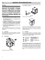
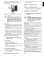
GENERAL RECOMMENDATIONS
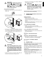
Lift the appliance using a lift truck, remove the base
and position the appliance
WARNING
CAREFULLY READ THE INSTALLATION, OPERATING AND MAINTENANCE INSTRUCTIONS BEFORE
INSTALLING THIS APPLIANCE. INCORRECT
INSTALLATION, ADAPTATIONS OR ALTERNATIONS COULD CAUSE DAMAGE TO PROPERTY
OR INJURY TO PERSONS. MALICIOUS DAMAGE,
DAMAGE DUE TO NEGLIGENCE, OR TO FAILURE
TO COMPLY WITH INSTRUCTIONS AND REGULATIONS, OR TO INCORRECT CONNECTIONS OR
UNAUTHORISED TAMPERING INVALIDATE ANY
WARRANTY AND RELIEVE THE MANUFACTURER
OF ALL LIABILITY.
1. Carefully read this instructions booklet, as it contains important advice for safe installation, operation and maintenance.
Keep this booklet to hand in a safe place for future
reference by other operators.
2. Installation should be carried out by qualified
engineers, in accordance with current regulations and with the manufacturer’s instructions.
3. The appliance should only be used by persons specifically trained in this operation.
4. Switch off the appliance in the event of failure or
malfunctioning.
Only have the appliance repaired by a service centre
authorised by the manufacturer and ask for original
spare parts.
A1
HANDLING
where it is to be installed.
Figure 3
Remove the protective film and ensure that the packaging material is disposed of correctly in compliance
with the regulations in force in the country where the
product is to be used.
A3
Use suitable means to move the appliance: a lift truck
or fork pallet trucks (the forks should reach more than
halfway beneath the appliance).
A2
Figure 2
DISPOSAL
All the packaging materials are environment friendly.
They may be kept without danger, recycled or burned
in a special waste incineration plant. Recyclable plastic
components are marked as follows:
UNPACKING
polyethylene
PE
PP
PS
Figure 1
Wear protective gloves to unpack.
4
polypropylene
polystyrene
foam
external wrapping film,
instruction bag.
top packaging panels,
straps
protective surround elements.
Wood and cardboard components may be disposed of
according to local regulations in force. Appliances that
have reached the end of their service life should be
suitably disposed of. The appliance should be dismantled according to regulations in force. All metal parts
are in stainless steel (AISI 304) and are removable.
Plastic parts are marked with the symbol of the material.
TECHNICAL DATA
MODEL
ET5AIDP /
ET5AIDPWS
/ ET5AIIT
ZUCI / AUCI /
EUCI
EUCAIML /
EUCAIMLG
EUCAIUSPH /
EUCIM
ZUCAI / AUCAI /
EUCAI
400-440V 3
400-415V 3N
Supply voltage:
V
400-415V 3N
400-415V 3N
400-415V 3N
- convertible to
V
220-240V 3
220-240V 3
220-240V 3
-
- single-phase version
V
220-240V 1N
220-240V 1N
220-240V 1N
-
Frequency
Hz
50 or 60
50 or 60
50 or 60
50 or 60
50 or 60
Max. power input
kW
6,85/8,85(*)
5.35/7,35(*)
6,85/8,85(*)
6,85/8,85(*)
5.35/7,35(*)
6,85/8,85(*) ($)
9,85/11,85(*) (&)
220-240V 3
220-240V 1N
Boiler heating elements
kW
6,0
4,5
6,0
6,0
4,5 - 6,0($) - 9,0(&)
Tank heating elements
kW
2,0
2,0
2,0
2,0
2,0
Water supply press. for atmospheric
boiler versions
kPa [bar]
50-700 [0,5-7]
50-700 [0,5-7]
50-700 [0,5-7]
50-700 [0,5-7]
50-700 [0,5-7]
Water supply press. for pressure boiler
versions
kPa [bar]
-
200-300 [2-3]
-
200-300 [2-3]
200-300 [2-3]
Water supply temperature
°C
15
50
50
50
50 / 15 (&)
Water supply hardness for models
without incorporated continuous water
softener
°f/°d/°e
14/8/10 max
14/8/10 max
14/8/10 max
14/8/10 max
14/8/10 max
Electric conductivity of water for models
without incorporated continuous water
softener
μS/cm
< 400
< 400
< 400
< 400
< 400
Water supply hardness for models with
incorporated water softener
°f/°d/°e
48/27/33,7 max
48/27/33,7 max
48/27/33,7 max
48/27/33,7 max
48/27/33,7 max
Concentration of chlorides in water
ppm
< 20
< 20
< 20
< 20
< 20
Rinse cycle water consumption
l
3,0
3,0 (**)
7,5
5,9 / 3,0 (**)
3,0 / 3,8 (%)
Boiler capacity
l
12
12
12
12
12
Tank capacity
l
23
23
23
23
23
Standard cycle time with water supply at
50°C
sec.
90-120-120
90-120-240
300-420-600/
360-540-660
120-180-300 /
95-125-245
90-120-240 /
90-113-173 (%)
Legal noise level Leq
dB(A)
<65
<65
<65
<65
<65
IPX4
IPX4
IPX4
IPX4
IPX4
Protection rating
Net weight for models without
incorporated continuous water softener
kg
68
68
68
68
68
Net weight for models with incorporated
continuous water softener
kg
71
71
71
-
71
H07RN-F
H07RN-F
H07RN-F
H07RN-F
H07RN-F
Power supply cable
ENGLISH
A4
(*) = If activated by software, coincidence of tank and boiler heating elements.
Table 1
400-415 V 3N
C
5,35 kW
6,85 kW
7,35 kW
8,85 kW
S
2
16A 3P+N
2
16A 3P+N
5X2,5 mm
2
16A 3P+N
16A 3P+N
20A 3P+N
25A 3P+N
5x2,5 mm
5x2,5 mm
5X2,5 mm
2
9,85 kW
5X2,5 mm
2
11,85 kW
5X4 mm2
400-440V 3
C
220-240V 3
S
4x2,5 mm
2
16A 3P
4x2,5 mm
2
16A 3P
2
16A 3P
2
16A 3P
2
4x2,5 mm
20A 3P
4x4 mm2
32A 3P
4x2,5 mm
4x2,5 mm
C
220-240V 1N
S
C
S
4x4 mm
2
20A 3P
2
3x6 mm
30A 1P+N
4x4 mm
2
20A 3P
3x6 mm2
40A 1P+N
4x4 mm
2
25A 3P
4x4 mm
2
32A 3P
4x6 mm
2
32A 3P
4x8 mm2
40A 3P
2
40A 1P+N
2
50A 1P+N
2
3x10 mm
50A 1P+N
3x16 mm2
63A 1P+N
3x10 mm
3x10 mm
C = Power supply cable
S = On/Off switch
Table 2
Standard cycle time may vary should the inlet water temperature and/or the boiler heating elements be different from
that indicated above.
(**) With dynamic feed pressure of 200 kPa [2 bar] for pressure boiler versions.
(%) For Wine Line versions only.
($) EUCAICLG, EUCAIWL
(&) EUCAICL, EUCAICLW
5
I
600
987
A
C
I
30
A
508
155
I
Q
58
431
403
379
C
S
A
612
Q
750-1000*
S
850
820
C
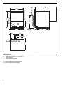
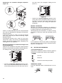
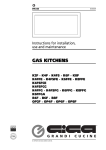
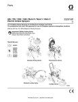
Figure 4 Installation diagram
Legend Figure 4
A - Water inlet pipe with ø 3/4” G fittings
C - Outlet pipe øi 40 mm (^) – øi 20 mm (*).
I - Power supply
S - Pipe inlet for detergents
Q - Unipotential screw
(^) - Only for model with free-fall drainage
(*) - Only for model with drain pump
6
431
69
-
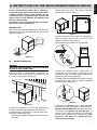
Make 4 holes Ø 9 mm on the support respecting
the distances shown in Figure 7.
431 mm
508 mm
Install a disconnecting switch with a capacity at
least equal to that given in the technical data table,
a 30mA residual current circuit breaker and an
overcurrent device (magnetothermal cut-out with
manual reset or fuse) between the appliance and
the mains power outlet.
The chosen device must be lockable in the open
position in case of maintenance.
RATING PLATE
The rating plate contains identification and technical
data and is located on the right-hand side panel of the
appliance (Figure 5).
Figure 7
-
Model LS6
PNC 9CGX 502003 05 Ser.N .123000001
AC 400V 3N
50Hz
Power Boiler
16500w
Power Tank
7500w
Power Max
26800w
Made in EEC
Model RT10 ED
PNC 9CGX502003 05
Ser.N .123000001
-
Put the dishwasher on the support by matching the
holes just made with the seats of the feet in the
appliance bottom panel (Figure 8).
Fix the dishwasher steadily using screws M8.
Figure 5
B1
WATER CONNECTION
WARNING
Watermark labelled machines must be installed in
accordance with AS/NZS 3500.1.
Figure 8
•
If the dishwasher is installed under a work plan, the
dimensions of the space, where it is inserted, must be
the same as those shown in Figure 6.
•
Connect the appliance water supply pipe “A”
(Figure 4) to the mains, fitting a cut-off cock, the filter provided and a pressure gauge between the
appliance and the mains (Figure 9).
In models with incorporated water softener, connect
the double non-return valve "B" (Figure 9) supplied
and the machine supply pipe.
870
!
B
Figure 9
Figure 6
Position the dishwasher and level the appliance by
turning the relative height-adjustable feet (Figure 5).
If the dishwasher is installed on a special support (eg.:
work plan), follow these steps:
- Accessing the appliance bottom panel and unscrew
the 4 feet.
•
Check that the dynamic water supply pressure,
measured between the appliance and the main, is
between 200 and 300 kPa for machines with pressure boiler and between 50 and 700 kPa for
machines with atmospheric boiler (test while dishwasher tank or boiler is filling with water). If the
pressure is too high, fit a suitable pressure
reducer on the inlet pipe.
7
ENGLISH
B INSTRUCTIONS FOR THE INSTALLER/MAINTENANCE PERSON
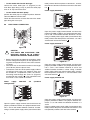
- On the model with free-fall drainage:
connect the waste outlet pipe “C” (Figure 4) to the
main drain pipe, fitting a trap, or place the outlet pipe
over an “S” trap set into the floor.
table), connect the three phases to terminals 1, 3 and 5,
the neutral to terminal 6 and the earth wire to the terminal .
Power supply 400-440V 3
- On the model with drain pump:
position the outlet pipe at a height anywhere between
750 and 1000 mm from the floor.
Check that about 3 litres of water flow out of the outlet
pipe during the rinse cycle.
L1
L2
L3
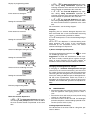
B2
ELECTRICAL CONNECTION
1
7
2
8
3
9
4
10
5
11
6
Figure 12
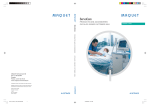
Open the power supply terminal board and insert the
jumpers provided as follows: one jumper between terminals 2 and 4 and another between terminals 4 and 6.
Using a suitable power supply cable (see technical data
table), connect the three phases to terminals 1, 3 and 5
and the earth wire to the terminal .
12
AC
..
0..
40
Power supply 220-230V 3
L1
Figure 10
!
•
•
•
CAUTION
THE EARTH AND ELECTRICAL CONNECTIONS SHOULD BE IN COMPLIANCE WITH NATIONAL REGULATIONS.
Before carrying out the electrical connection, check
that the voltage and frequency on the appliance rating plate correspond to those of the mains electricity supply.
The earth wire at the terminal end must be longer
(max. 20 mm) than the phase wires.
Connect the earth wire of the power supply cable to
an efficient earth clamp. The appliance must also
be included in a unipotential system, the connection being made through the screw “Q” (Figure 4)
marked with the symbol “ ”. The unipotential wire
must have a cross section of 10 mm2.
Power
supply
configuration)
400-415V
3N
L2
L3
Figure 13
Open the power supply terminal board and insert the
jumpers provided as follows: one jumper between terminals 1 and 2, one between terminals 3 and 4 and
another between terminals 5 and 6. Using a suitable
power supply cable (see technical data table), connect
the three phases to terminals 1, 3 and 5 and the earth
wire to the terminal .
Power supply 220-230V 1N
(standard
L1
L2
L3
Figure 14
Figure 11
Open the power supply terminal board and insert the
jumpers provided as follows: one jumper between terminals 2 and 4 and another between terminals 4 and 6.
Using a suitable power supply cable (see technical data
8
Open the power supply terminal board and insert the
jumpers provided as follows: two jumpers between terminals 1, 3, 5 and another two between terminals 2, 4
and 6.
Using a suitable power supply cable (see technical data
table), connect the phase and neutral to terminals 5 and
6 respectively and the earth wire to the terminal .
-
Check for obstruction on the waste outlet pipe and
the overflow aperture.
C1..C8 CALL THE SERVICE CENTRE
E1..E8 CALL THE SERVICE CENTRE
11
-
12
The appliance continues to operate, but appropriate checks by a technician are recommended.
F21..F22 CALL THE SERVICE CENTRE
Figure 15
B4
DETERGENT/RINSE-AID DISPENSERS AND
SETTINGS
Connect the energy peak controller across terminals 11
and 12.
!
CAUTION
A normally open (n.o.) contact of the
controller must be connected across terminals 11 and 12. When this contact
closes the boiler heating elements are
disconnected. Using the dishwasher in
these conditions may increase the cycle
time.
Safety devices
• An automatic reset thermoamperometric protective
device incorporated in the windings of the electric
pump cuts off the electricity supply in the case of
malfunctioning.
• In the event of water mains failure, a device prevents water in the boiler from returning into the
mains.
• An overflow pipe, connected to the drainage outlet,
maintains the water in the tank at a constant level.
• On models with a drain pump, a supplementary
level control device activates if the main level control device is faulty.
Failure to comply with safety rules and regulations
relieves the manufacturer of all liability.
B3
WARNING MESSAGES DISPLAYED ON THE
CONTROL PANEL
A1
-
Check that the cock is open.
Check that the water inlet filter is clean.
Check the minimum mains pressure (not less than
50 kPa).
Check that the overflow pipe is inserted (for appliances without drain pump only).
B1
-
NO WATER
INEFFICIENT DRAINAGE
Check if the overflow has been removed.
Check for obstruction on the waste outlet pipe and
the overflow aperture.
B2
TANK WATER LEVEL TOO HIGH
!
CAUTION
The following paragraph does not apply
for models ET5AIDP / ET5AIDPWS /
ET5AIIT, since the appliance already has
the prearrangements for the detergent/
rinse aid dispensers.
If the appliance is connected to a water softener or
osmotic device, contact the detergent supplier for a
specific product.
Peristaltic dispensers (rinse-aid and detergent) require
periodic maintenance. The internal hose of the rinseaid dispenser should undergo periodic maintenance
(at least once or twice a year).
1. Dishwasher with incorporated detergent dispenser pump (Figure 16).
Pump “R” dispenses about 0.9 g/s of detergent. When
the appliance is filled with water for the first time in the
day, it dispenses about 44 g of detergent in 45 sec.,
thereby providing a concentration of 2 g/l. Pump “R”
dispenses about 6 g in 6 sec. at each cycle.
Dispenser operating time may be changed, following
the instructions given in the next paragraph.
Insert the hose provided in the kit into the detergent
container.
2. Dishwashers with incorporated peristaltic
rinse-aid dispenser pump (Figure 16).
Pump “S” dispenses about 0.1 g/s of rinse-aid. It dispenses 0.3 g in 3 sec. at each rinse.
Dispenser operating time may be changed, following
the instructions given in the next paragraph.
Insert the hose provided in the kit into the rinse-aid
container (in the versions without incorporated rinseaid dispenser only).
3. Dishwashers with incorporated rinse-aid diaphragm dispenser pump (Figure 16).
Pump “T” is installed in appliances with pressure boiler.
Dispensed amounts may be changed according to the
instructions given in the paragraph below.
Insert the supplied hose into the rinse-aid container (in
the versions without incorporated rinse-aid dispenser
only).
9
ENGLISH
Connections provided for energy control
This appliance is designed for an external energy consumption control.
the wash cycle (see paragraph “Setting the dispensers”).
Connections for automatic detergent dispenser
(Figure 16)
P
N
Figure 18
•
Connect the rinse-aid dispenser between terminals 8 and 9. These connection points are live during filling of the tank and at the end of the rinse
cycle for a set time (see “setting the dispensers”
paragraph).
T
R
D
S
Figure 16
There is a ready-made impression “N” to be perforated
(Ø 8 mm) for positioning the detergent concentration
measuring sensor.
Inside the tank there is a hole “P” (Ø 10 mm) closed
with a plug, which may be used for mounting a liquid
detergent injector.
The Ecotemp versions have a hole “N” (Ø 22 mm)
closed with a plug. The sensor and liquid detergent
injector should be installed without prejudicing the
watertightness of the appliance.
Electrical connections for automatic detergent and
rinse-aid dispensers
Terminals are available on the power supply terminal
board for the electrical connection of external dispensers working at 220…240 V. Max. power 30 VA.
L1
MANUAL ACTIVATION
Whenever the detergent containers are replaced, it
may be necessary to activate the dispensers manually
in order to fill the hoses and eliminate any air.
Simultaneously press the buttons, as shown in the figures below. If necessary, repeat this operation several
times.
1
2
3
DETERGENT DISPENSER
1
2
3
DISPENSER RINSE-AID
In the appliances with pressure boiler, the diaphragm
dispenser pump may be manually activated by pressing screw “D” (Figure 16).
B5
SETTING THE DISPENSERS
1) Peristaltic dispensers
All operations should be carried out with the appliance
switched on, the door open and no cycle selected.
LEGEND
L2
Increase
L3
Decrease
Confirm or select next parameter
Figure 17
•
Connect the detergent dispenser between terminals 7 and 9. These connection points are live for a
set time during filling of the tank and at the start of
SEQUENTIAL START
Press the indicated buttons simultaneously for 5 seconds:
1
10
GEn
if the detergent dispenser only operates during filling electrovalve operation for
restoring the boiler level; terminals 7-9 of the main
terminal board are powered at the same time.
-
if the rinse-aid dispenser only operates during filling electrovalve operation for
restoring the boiler level; terminals 8-9 of the main
terminal board are powered at the same time.
3
2
1
-
Initial amount of detergent:
dln
if the rinse-aid dispenser only operates during wash pump operation; terminals 8-9 of
the main terminal board are powered at the same
time.
For connections, see the wiring diagram.
Setting the activation time:
45
1
2
3
Example:
Supposing that an external detergent dispenser has
been connected with a tank concentration measuring
sensor, a standard setting could be as follows:
Initial amount of rinse-aid:
rln
the dispenser is not activated during filling of
the tank.
Setting the activation time:
10
1
2
3
Amount of detergent during the cycle:
dEt
Setting the activation time:
8
1
2
3
Amount of rinse-aid during the cycle:
rAl
Setting the activation time:
4
1
2
3
the dispenser is activated during wash
pump operation and, thanks to the concentration
measured by the conduction sensor, the correct
amount of detergent is dispensed.
2) Rinse-aid diaphragm dispenser
To change the dispensed amount, turn
on screw
“D” accordingly (Figure 16).
Suggestion: to check the effectiveness of the rinseaid, look at freshly washed glasses against the light.
Drops of water remaining on the glass indicate an
insufficient amount while streaks indicate an excess.
Changing the detergent/rinse-aid type
If changing to a different detergent/rinse-aid type
(even one by the same manufacturer), you must rinse
the suction and pressure hoses with fresh water before
connecting the new detergent/rinse-aid container. Otherwise, the mixing of different types of detergent/rinseaid will cause crystallisation, which may result in a
breakdown of the dosing pump. Failure to observe this
condition will invalidate the guarantee and product liability.
Exit from programming mode:
B6
GEn
•
•
Notes for external dispensers:
-
if the detergent dispenser only operates during wash pump operation; terminals 7-9 of
the main terminal board are powered at the same
time.
•
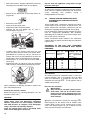
MAINTENANCE
Descale the boiler, the internal surfaces of the tank
and the appliance water piping once or twice a
year.
Descale the rinse and wash jets every month using
vinegar or a descaling agent.
The internal hose of the rinse-aid and detergent
peristaltic dispenser should undergo periodic maintenance (once or twice a year).
Prolonged period of inactivity
If the dishwasher is not to be used for a long time, proceed as follows:
11
ENGLISH
Display of programming mode:
•
•
•
•
•
Close the water supply cock.
Completely drain the tank.
Remove and carefully clean the filters.
Completely drain the incorporated dispenser
hoses, removing them from the containers. Repeat
the procedure described in the paragraph “Manual
activation” at least 3 times.
Completely drain the boiler by simultaneously
pressing the buttons as shown in the figure.
1
•
2
3
A buzzer indicates completion of drainage.
Spread a thin film of Vaseline oil over all the stainless steel surfaces.
Preventive maintenance
The preventive maintenance call may be activated
(see service manuals).
Upon reaching the set number of cycles (e.g. 20000),
appears on the display.
This message advises calling a qualified technician for
a general check-up of the state of the appliance.
Only for models with door lock device
Checks for inspection
NOTICE: on the right side of the machine there is a
hole, indicated by a “CHECK POINT” label (Figure 19),
for accessing the washing chamber with a temperature
measurer.
In this way it is possible to check the temperature
reached by the dishes during the wash cycle (in
accordance with the HTM [Health Technical Memorandum] 2030 guidelines).
Figure 19
12
INSTRUCTIONS FOR THE USER
Our appliances have been studied and optimised to give high performance. This appliance must be used exclusively
for the purpose for which it has been designed, i.e. for washing dishes with water and specific detergents. Any other
use is to be considered improper.
This appliance does not carry out the rinse cycle should there be no supply water; it stops all functions with an error
message “A1” (also see “Warning messages”).
TIPS
•
•
•
•
•
•
•
•
Carry out a couple of cycles without dishes to flush out any industrial grease which has remained in the
tank and piping.
Avoid washing decorated dishes.
Do not allow silverware to come into contact with other metals.
Do not allow food to dry on the dishes.
Remove large food scraps from the dishes to prevent clogging the filters.
Pre-wash the dishes by spraying them with cold or lukewarm water, without using any detergent.
Use automatic dispensers for the detergent.
If there is no automatic dispenser, pour a non-foaming detergent into the tank when the water has reached
the washing temperature.
CONTROL PANEL
A
B
K
D
J
H
F
1
2
3
E
E
J
H
F
LEGEND:
A = on/off
B = drain/self-cleaning cycle
K = display
D = “tank” indicator light
=
=
=
=
“boiler” indicator light
wash cycle 1
wash cycle 2
wash cycle 3
Figure 20
The temperature shown on the display is that of the boiler if the indicator light “E” is on or of the tank if the light “D” is on.
The tank temperature is displayed during the wash cycle and the boiler temperature during the rinse cycle.
C1
•
•
•
•
STARTING
Open the water supply cock.
Switch on at the mains.
Open the door and check that all the components
are in their correct position.
Close the door and press button “A”.
For atmospheric versions only:
Warning, this dishwasher does the first tank filling
through several consecutive hot rinse cycles, while the
display shows the message FILL (flowing).This system
let save up to 30% of time than traditional models.
If the door is opened during this stage the message
"CLOSE" will appear on the display:
The indicator light of button “A” (Figure 20) comes on,
indicating that the dishwasher is powered and that
water is being introduced and heated. The word “FILL”
is shown on the display during the entire filling and
heating stage:
CLO
The filling and heating stage has finished when the display shows the tank temperature:
55°C
FILL
13
ENGLISH
C
To display the boiler temperature during heating of the
tank, open the door and press the button “J”
(Figure 20).
selected cycle, the cycle is stopped and the door is
released.
•
1
C2
WASH CYCLES
The wash cycle includes one wash with hot water and
detergent (min 55 °C or min 150 °F for Marine USPH
versions) and one rinse with hot water and rinse-aid
(min 82 °C or min 180 °F for Marine USPH versions).
Table of times
Standard cycle time with supply water at 50 °C.
•
If the dishwasher is equipped with detergent and
rinse aid level sensors the message . may
appear on the display. This indicates no detergent
in the external tank.
After 5 cycles performed with a lack of detergent,
the dishwasher inhibits the start of other wash
cycles. Therefore the detergent level in the tank
must be restored (see par. “Manual activation”).
The lack of rinse aid is signalled by the message
; this message is a warning that does not
stop performance of the wash cycles.
Wash cycles:
1
2
3
ZUCI/ AUCI/ EUCI/ ET5IIT
ZUCAI/ AUCAI/ EUCAI
90”
120”
240”
EUCAIUSPH
120”
180”
300”
EUCIM
95”
125”
245”
EUCAIWL
90”
113”
173”
EUCAIML
300”
420”
600”
EUCAIMLG
360”
540”
660”
Standard cycle time with supply water at 15 °C.
1
2
3
EUCAICL, EUCAICLW
90”
120”
240”
ET5IDP / ET5IDPWS / ET5AIIT
90”
120”
120”
A device lengthens the cycle time if the water in the
boiler has not reached the minimum temperature for
correct rinsing.
The cycle times and the temperature may be personalised (e.g. increase of the rinse time and temperature).
The cycle times should only be set by a specialised
technician.
- Cycle I
For lightly soiled dishes: press button “J” (Figure 20)
(see table of times).
1
2
- Cycle II (recommended)
For normally dirty dishes: press button “H” (Figure 20)
(see table of times).
1
2
3
- Cycle III
For very dirty dishes: press button “F” (Figure 20) (see
table of times).
1
2
3
Only for models with incorporated water softener
C3
OPERATION
The filling and heating stage has finished when the display shows the tank temperature:
55°C
The appliance is then ready for use:
• Open the door.
• Pour the required amount of detergent into the tank
(in models without automatic dispenser).
• Insert the rack containing the dirty dishes.
• Close the door and select the suitable wash cycle;
the corresponding indicator light comes on and the
wash cycle starts.
Only for models with door lock device
• A closing device locks the door for the entire duration of the wash cycle. By pressing the button of the
14
If the salt container is empty, the message
is displayed at the start or end of the cycle.
Place the salt in the special container, following the
instructions given in the section "Undercounter dishwasher with incorporated continuous water softener”.
•
•
To stop the wash cycle, just press the selected
cycle button or open the door.
To continue the wash cycle, just press the selected
cycle button or close the door. The cycle starts
again from where it stopped.
Only for models with door lock device
At the end of the rinse stage the dishwasher carries
out a pause stage of 1 minute 45 seconds, during
which the time remaining for completion of the cycle is
displayed.
•
ENGLISH
This procedure complies with the parameters required by
HTM (Health Technical Memorandum) 2030 guidelines.
In this case door lock hinders door opening, so washing cycle cannot be interrupted.
At the end of the wash, the dishwasher emits a
series of beeps and “END” blinks on the display:
END
Figure 23
•
Open the door and remove the rack containing the
clean dishes.
WARNING
The appliance will not remove burnt food deposits
from dishes. Dishes with burnt-on food deposits
should be cleaned mechanically/chemically (for
example, pre-wash under running water) before
putting them in the dishwasher.
WARNING
The use of “foaming”/non-specific detergents or in
any case detergents used in different ways from that
prescribed by the manufacturer, can cause damage
to the dishwasher and compromise washing results.
Figure 24
•
YELLOW container for cutlery: insert items, with
the handles pointing downwards, in each container.
• Available as accessories: dividers for glasses and
rack for dishes with maximum diameter of 320 mm.
Note: if only one type of dish rack is to be used, it is
advisable to choose the GREEN rack.
C4
WARNING
Failure to remove the residuals of detergent possibly used for manual prewash can cause malfunctioning of the dishwasher and compromise
washing results.
Change the water in the tank at least twice a day.
BLUE rack for glasses: the glasses should be
placed upside down.
END OF WORK AND DAILY CLEANING
The appliance is designed to carry out an automatic
cleaning cycle to help flush out any residues and to
guarantee greater health and hygiene:
• Open the door and take out the rack containing the
clean dishes.
• Remove the tank filters and the overflow “W”.
Type of racks and loading
W
Figure 25
Figure 21
•
YELLOW rack: for 18 plates with maximum diameter of 240 mm.
Figure 22
•
GREEN rack: for 12 bowls with maximum diameter
of 240 mm.
•
•
Close the door.
Select the drain cycle by pressing button “B”
(Figure 20).
•
The message "CLE" ("CLEAN") will be displayed
throughout the drain cycle:
CLE
15
•
After a few minutes, 3 beeps indicate the end of the
cleaning cycle and “END” blinks on the display:
END
•
Switch off the dishwasher by pressing button “A”
(Figure 20).
Do not wash the appliance using direct or highpressure water jets.
To reduce the emission of pollutants into the environment, clean the appliance (externally and where necessary
internally)
with
products
having
a
biodegradability of over 90%).
C5
•
•
•
•
Switch off at the mains.
Close the water supply cock.
Replace the filters and the overflow.
Remove the top and bottom jets “F” and “I”,
unscrewing the ring nut “H”.
C
F
H
UNDERCOUNTER DISHWASHER WITH
INCORPORATED CONTINUOUS WATER
SOFTENER
These models have a continuous softener in the dishwasher water circuit. By means of special resins, this
device removes the calcareous substances from the
feed water, supplying decalcified water for washing.
For the continuous softener to work properly the resins
must be regenerated periodically, with frequency
depending on the hardness of the water and the number of wash cycles carried out.
Unlike conventional water softeners, this continuous
softener does not require machine stops for regenerating the resins.
I
D
Figure 26
•
•
•
Carefully clean the washing and rinse jets and
clean everything with hot water and neutral detergent/detersive, if necessary using a soft brush or
sponge. Do not use sharp implements to clean the
nozzle holes, which could otherwise be damaged.
Remove filters “C” and “D” and clean them under a
water spray.
Remove the filter “Z” and clean away any remained
food in order to avoid blocking the draining system.
2
Z
1
Figure 27
Upon completion of cleaning operations, replace the
parts removed previously.
Cleaning the exterior surfaces
Before carrying out any cleaning operations, turn off
the power at the mains.
WARNING
Clean the stainless steel surfaces using warm
soapy water; never use detergents containing
abrasive substances nor steel scrapers, common
wire wool, brushes or scrapers; rinse thoroughly
using a wet cloth and carefully wipe dry.
Clean the control panel using a soft damp cloth
and a neutral detergent if necessary.
16
AUTONOMY OF THE FULL SALT CONTAINER
ACCORDING TO THE CHANGE IN INLET WATER
HARDNESS
The salt container
must
be
filled
approximately
every (*):
Using cycle 2 for 30
cycles/day, the salt
container must be filWater hardness
led
approximately
every (*):
°f
°d
°e
Cycles
Days
15
8,4 10,5
1168
39
20
11,2
14
837
28
25
14
17,5
589
19
30
16,8 21,1
506
17
35
19,6 24,6
423
14
40
22,4 28,1
341
11
The factory setting of max. outlet water hardness is 10 °f/ 5.6 °d/ 7 °e.
(*) Considering a rinse time according to the factory settings.
Salt container
The water can only be softened if there is salt in the
special container. The salt container must be filled
when the dishwasher is started the first time and
whenever the message appears and an
audible alarm sounds.
No salt in the container
IMPORTANT:
! Only use coarse salt with a purity level of
99.8% NaCl. The use of salt with a lower
purity level can cause clogging of the salt
container filter and malfunctioning of the
water softener.
When the salt container is empty, the message
appears on the display and an audible alarm
sounds. Wash cycles can be started just the same,
even if the display signals no salt; in which case the
water used for washing is not softened.
How to fill the salt container
• Switch off the dishwasher by pressing button “A”
(Figure 20).
•
Refit the cap of container "A", turning it clockwise
and making sure it is tight.
IMPORTANT:
! The message may appear
for several wash cycles even after topping-up the salt, as the salt must circulate in the entire system. Correct
operation of the dishwasher is not,
however, affected.
The salt container always has water in it, therefore it is
normal if water comes out during filling.
C6
•
WARNING MESSAGES DISPLAYED ON THE
CONTROL PANEL
Unscrew cap "A" (Figure 28) of the salt container,
turning it anticlockwise.
A1
-
A
Check that the cock is open
Check that the water inlet filter is clean
Check the minimum mains pressure (not less than
50 kPa)
Check that the overflow pipe is inserted (for appliances without drain pump only)
-
B1
-
Pour approx. 1.5 kg of coarse salt [NaCl] in container
"A" (an amount sufficient to fill the salt container up to
the rim) using the special funnel supplied (Figure 29).
INEFFICIENT DRAINAGE
Check if the overflow has been removed.
Check for obstruction on the waste outlet pipe and
the overflow aperture.
Figure 28
•
NO WATER
B2
-
TANK WATER LEVEL TOO HIGH
Check for obstruction on the waste outlet pipe and
the overflow aperture.
C1..C8 CALL THE SERVICE CENTRE
NaCl
(1,5 kg)
E1..E8 CALL THE SERVICE CENTRE
-
The appliance continues to operate, but appropriate checks by a technician are recommended.
F21..F22 CALL THE SERVICE CENTRE
C7
Figure 29
!
•
IMPORTANT:
only salt may be placed in the salt container. Do not introduce any other chemical substances such as detergent, rinse
aid or descaling agent, since these
would inevitably damage the appliance.
Such damage invalidates any warranty
and relieves the manufacturer of all liability.
Remove any traces of salt from the filling hole, the
container thread and the closing cap seal.
RESIDUAL RISKS
The machine has several risks that were not completely eliminated from a design standpoint or with the
installation of adequate protection devices.
Nevertheless, through this manual the Manufacturer
has taken steps to inform operators of such risks, carefully indicating the personal protection equipment to be
used by them.
Sufficient spaces are provided for during the machine
installation phases in order to limit these risks.
To preserve these conditions, the corridors and areas
around the machine must always be:
• kept free of obstacles (e.g. ladders, tools, containers, boxes, etc.);
17
ENGLISH
!
IMPORTANT:
Open the salt container only when the
message is displayed. Opening the cap when the message
is not displayed can cause spilling
of the saline solution and compromise
correct machine operation.
• clean and dry;
• well lit.
For the Customer’s complete information, the residual
risks remaining on the machine are given below; such
actions are to be considered incorrect and therefore
strictly forbidden.
RESIDUAL
RISK
DESCRIPTION OF HAZARDOUS
SITUATION
Slipping or
falling
The operator can slip due to water
or dirt on the floor.
Burns
The operator deliberately or unintentionally touches some components inside the machine or dishes
at the outfeed without using gloves
or without allowing them to cool.
Possible contact with water above
60°C / 140°F.
Electrocution
Contact with live parts during maintenance operations carried out with
the electrical panel powered.
Falling from
above
The operator intervenes on the
machine using unsuitable systems
to access the upper part (e.g. rung
ladders, or climbs on it).
Tipping of
loads
During maintenance on the
machine or the packing containing
the machine with the use of unsuitable accessories or lifting systems
or with load unbalanced.
Chemical
Contact with chemical substances
(e.g. detergent, rinse aid, scale
remover, etc.) without taking adequate safety precautions. Therefore always refer to the safety
cards and labels on the products
used.
18
TROUBLESHOOTING
DISHWASHER DOES NOT WASH
WELL
1. Check if the suction filter is dirty and clean it thoroughly.
2. Check if the wash jets are clogged by solid food remains.
3. Check that the initial amount of detergent or subsequent additions are
correct.
4. The selected wash cycle is too short. Repeat the cycle.
5. Check that the tank temperature is between 55°C and 65°C.
6. Check that the dishes are stacked correctly in the racks.
GLASSES AND DISHES ARE
NOT DRIED PROPERLY
1. Check the instructions for the amount of rinse-aid (see “setting the
dispensers” paragraph).
2. Check that there is rinse-aid in the container and if necessary top up.
3. Check the set amount of rinse-aid (see “setting the dispensers” paragraph).
4. Check that the water temperature is between 80°C and 90°C.
CONDENSATION ON GLASSES
1. Check that there is rinse-aid in the container and if necessary top up.
2. Check the set amount of rinse-aid (see “setting the dispensers” paragraph).
3. Remove the rack of glasses immediately the cycle has ended.
STAINS ON THE GLASSES
1. Only use “non-foaming” products for professional dishwashers.
EXCESSIVE FOAM IN THE TANK
1. Check that the wash water temperature is not less than 50°C.
2. Check if the amount of product dispensed by the detergent dispenser is
excessive (see “setting the dispensers” paragraph).
3. Ensure that the tank has not been cleaned with unsuitable cleaners.
Drain the tank and rinse thoroughly before new wash cycles.
4. If a foaming detergent has been used, drain and refill the tank with
water until the foam disappears.
SMEARS OR SPOTS ON THE
GLASSES
1. Reduce the amount of rinse-aid (see “setting the dispensers” paragraph).
THE WASH OR RINSE ARMS
TURN SLOWLY
1. Remove and thoroughly clean the arms.
2. Clean the wash pump suction filter.
19
ENGLISH
D
20