1
2354235 11/2008
Altivar 312
Variable speed drives
for asynchronous motors
Communication variables manual
BBV51701
06/2009
www.schneider-electric.com
Contents
Important Information __________________________________________________________________________________________ 4
Before you begin _____________________________________________________________________________________________ 5
Documentation structure _______________________________________________________________________________________ 6
Presentation _________________________________________________________________________________________________ 7
Communication bus monitoring __________________________________________________________________________________ 9
Supervision and control in LINE mode ___________________________________________________________________________ 10
Function compatibility ________________________________________________________________________________________ 14
IEC 61800-7 variables ________________________________________________________________________________________ 16
Control variables ____________________________________________________________________________________________ 19
Monitoring variables __________________________________________________________________________________________ 21
Identification variables ________________________________________________________________________________________ 26
Configuration and adjustment variables __________________________________________________________________________ 27
Replacing an ATV28 with an ATV312 ____________________________________________________________________________ 57
Code index _________________________________________________________________________________________________ 58
Address index ______________________________________________________________________________________________ 63
BBV51701 06/2009
3
Important Information
NOTICE
Read these instructions carefully, and look at the equipment to become familiar with the device before trying to install, operate, or maintain
it. The following special messages may appear throughout this documentation or on the equipment to warn of potential hazards or to call
attention to information that clarifies or simplifies a procedure.
The addition of this symbol to a Danger or Warning safety label indicates that an electrical hazard exists, which will result in
personal injury if the instructions are not followed.
This is the safety alert symbol. It is used to alert you to potential personal injury hazards. Obey all safety messages that follow
this symbol to avoid possible injury or death.
DANGER
DANGER indicates an imminently hazardous situation, which, if not avoided, will result in death or serious injury.
WARNING
WARNING indicates a potentially hazardous situation, which, if not avoided, can result in death, serious injury or
equipment damage.
CAUTION
CAUTION indicates a potentially hazardous situation, which, if not avoided, can result in injury or equipment
damage.
CAUTION
CAUTION, used without the safety alert symbol, indicates a potentially hazardous situation which, if not avoided,
can result in equipment damage.
PLEASE NOTE
The word "drive" as used in this manual refers to the controller portion of the adjustable speed drive as defined by NEC.
Electrical equipment should be installed, operated, serviced, and maintained only by qualified personnel. No responsibility is assumed by
Schneider Electric for any consequences arising out of the use of this product.
© 2009 Schneider Electric. All Rights Reserved.
4
BBV51701 06/2009
Before you begin
Read and understand these instructions before performing any procedure with this drive.
DANGER
HAZARD OF ELECTRIC SHOCK, EXPLOSION, OR ARC FLASH
• Read and understand this manual before installing or operating the Altivar 312 drive. Installation, adjustment, repair, and
maintenance must be performed by qualified personnel.
• The user is responsible for compliance with all international and national electrical code requirements with respect to grounding of
all equipment.
• Many parts of this drive, including the printed circuit boards, operate at the line voltage. DO NOT TOUCH. Use only electrically
insulated tools.
• DO NOT touch unshielded components or terminal strip screw connections with voltage present.
• DO NOT short across terminals PA/+ and PC/– or across the DC bus capacitors.
• Before servicing the drive:
- Disconnect all power, including external control power that may be present.
- Place a “DO NOT TURN ON” label on all power disconnects.
- Lock all power disconnects in the open position.
- WAIT 15 MINUTES to allow the DC bus capacitors to discharge.
- Measure the voltage of the DC bus between the PA/+ and PC/– terminals to ensure that the voltage is less than 42 Vdc.
- If the DC bus capacitors do not discharge completely, contact your local Schneider Electric representative. Do not repair or
operate the drive
• Install and close all covers before applying power or starting and stopping the drive.
Failure to follow these instructions will result in death or serious injury.
DANGER
UNINTENDED EQUIPMENT OPERATION
• Read and understand this manual before installing or operating the Altivar 312 drive.
• Any changes made to the parameter settings must be performed by qualified personnel.
Failure to follow these instructions will result in death or serious injury.
WARNING
DAMAGED DRIVE EQUIPMENT
Do not operate or install any drive or drive accessory that appears damaged.
Failure to follow these instructions can result in death, serious injury, or equipment damage.
WARNING
LOSS OF CONTROL
• The designer of any control scheme must
- consider the potential failure modes of control paths and, for certain critical control functions,
- provide a means to achieve a safe state during and after a path failure.
Examples of critical control functions are emergency stop and overtravel stop.
• Separate or redundant control paths must be provided for critical control functions.
• System control paths may include communication links. Consideration must be given to the implications of unanticipated
transmission delays or failures of the link.a
Failure to follow these instructions can result in death, serious injury, or equipment damage.
a. For additional information, refer to NEMA ICS 1.1 (latest edition), “Safety Guidelines for the Application, Installation, and Maintenance of Solid State Control” and to
NEMA ICS 7.1 (latest edition), “Safety Standards for Construction and Guide for Selection, Installation and Operation of Adjustable-Speed Drive Systems.”
BBV51701 06/2009
5
Documentation structure
The following Altivar 312 technical documents are available on the Schneider Electric website (www.schneider-electric.com) as well as on
DVD-ROM (reference VW3A8200).
Installation manual
This manual describes how to install and wire the drive.
Programming manual
This manual describes the functions, parameters and use of the drive terminal (integrated display terminal, optional graphic display terminal
and optional remote terminal).
The communication functions are not described in this manual, but in the manual for the bus or network used.
Simplified manual
This manual is a simplified version of the User manual.
Quick Start sheet
The Quick Start describes how to wire and configure the drive to start motor quickly and simply for simple applications. This document is
delivered with the drive.
Communication manuals: Modbus, CANopen, ...
These manuals describe the assembly, connection to the bus or network, signaling, diagnostics, and configuration of the communicationspecific parameters.
They also describe the protocol communication services.
Communication variables manual
The Communication variables manual defines the drive control processes and the drive variables which can be accessed by the
communication buses: Modbus, CANopen, ...
6
BBV51701 06/2009
Presentation
The Altivar 312 can be connected directly to Modbus and CANopen buses by means of an RJ45 connector, which supports both protocols.
The communication function provides access to the drive’s configuration, adjustment, control and monitoring functions.
The "Communication variables" User's Manual defines the drive control processes and the drive variables which can be accessed by these
buses.
It supplements each of the following manuals:
• Modbus
• CANopen
• Profibus
• DeviceNet
These documents should be referred to for the hardware and software setup specific to each bus.
We also recommend consulting the Programming Manual for additional explanations (operation, factory settings, etc).
If the SoMove software workshop is used, consult the on-line help provided.
The communication variables are listed with:
• their address •••• in decimal format for Modbus and Profibus,
• their index and subindex address ••••/•• in hexadecimal format for CANopen.
The rule to get the DeviceNet address from the Modbus address is described in the DeviceNet manual.
They are grouped into several different tables according to the following criteria:
• IEC 61800-7 (CiA 402)
• control variables
• monitoring variables
• identification variables
• configuration and adjustment variables
Read/write
Whether the parameters have read and/or write access is indicated in the "Read/Write" column with the following codes:
• R: read only, drive stopped or running
• R/WS: read access when drive stopped or running and write access only when drive stopped
• R/W: read and write access when drive stopped or running
Authorized addresses
WARNING
LOSS OF CONTROL
Only the addresses and values defined in this document can be used. Any other address or value must be considered to be reserved
and must never be written to.
Failure to follow these instructions can result in death, serious injury, or equipment damage.
BBV51701 06/2009
7
Control modes
Control and reference channels
The control and the reference may originate from different channels:
- the terminal block
- the built-in keypad
- the remote display terminal
- Modbus
- CANopen, DeviceNet, Profibus
These channels are managed:
- either in priority mode,
- or in deterministic mode.
The "Function access level (LAC)" and "Mixed mode (CHCF)" parameters are used to select the run mode.
Operation is described in detail in the Programming Manual ("Control menu" section).
Priority stops
In line mode, stop requests which can be activated by the terminals or by the remote display terminal have priority:
Type of stop
From
Fast stop
LI2 to LI6
Drivecom state
reached
"Operation enabled"
DC injection stop
LI2 to LI6
"Operation enabled"
Freewheel stop
LI2 to LI6
"Switch on disabled"
3-wire control stop via
LI1
"Switch on disabled"
STOP logic input (LI1)
(3-wire control)
Stop by the display terminal STOP key
"Switch on disabled"
8
Actions for restoring control of the Altivar using the fieldbus
- Set the logic input assigned to the "fast stop" function to 1
(active at 0)
- Set the logic input assigned to the "injection stop" function to 0
(active at 1)
- Set the logic input assigned to the "freewheel stop" function to 1
(active at 0)
- Perform the transitions required to return the drive to "run" status
- Set the logic input assigned to STOP to 1 (active at 0)
- Perform the transitions required to return the drive to "run" status
- Release the Stop key
- Perform the transitions required to return the drive to "run" status
BBV51701 06/2009
Communication bus monitoring
In the event of loss of communication the drive behaviour can be configured via the "SLL" or "COL" parameters (page 53). This configuration
is saved if the power supply is disconnected.
In its factory setting, loss of communication triggers a detected fault (COF, CNF, SLF) with freewheel stopping.
BBV51701 06/2009
9
Supervision and control in LINE mode
IEC 61800-7 status chart
Key
MSK - ETA masked by 16#006F
Enter the status
chart
All states
0
13
Not ready to switch on
ATV powered off
Malfunction
reaction active
MSK= 16#0000
MSK= 16#xxxx
IEC 61800-7 drive status
Drive status applied to ATV
MSK= 16#xxxx
"ATV terminal display"
Transition
condition X
CMD = 16#xxxx
Fault cleared and
ATV fault state reset
CMD =16#0080
1
Switch on disabled
ATV locked
15
Detected
fault
14
Malfunction
ATV in fault state
MSK = 16#0008
MSK= 16#0040
Disable voltage
CMD = 16#0000
or
modification of
9 a configuration
parameter
(motor stopped)
or
STOP key on
display terminal
or
STOP at terminals
"nSt"
Shutdown
CMD =16#0006 2
Disable
voltage
CMD = 16#0000
or
7 modification of
a configuration
parameter
(motor stopped)
or
Quick stop
CMD = 16#0002
Ready to switch on
ATV waiting
MSK = 16#0021
"nSt"
8
Shutdown
CMD =16#0006
Switch on
CMD =16#0007 3
3A
Enable
operation
CMD =16#xxxF
6
Shutdown
CMD =16#0006
Switched on
ATV ready
Disable voltage
CMD = 16#0000
or
modification of
a configuration
12 parameter
(motor stopped)
or
STOP key on
display terminal
Disable
or
voltage
STOP at terminals
CMD = 16#0000
10
or
modification of
a configuration
parameter
(motor stopped)
or
Quick stop
CMD = 16#0002
Quick stop active
Emergency stop
MSK = 16#0023
"nSt"
Enable
Disable
operation 4
5 operation
CMD =16#xxxF
CMD =16#0007
Operation enabled
ATV running
MSK = 16#0027
MSK =16#0007
"rdY, dCb"
Quick stop
CMD =16#0002
11
"rUn, rdY, ..."
Examples:
ETA = 16#0627 : Normal stop or
Forward operation, speed reached
ETA = 16#8627 : Reverse operation, speed reached
ETA = 16#0227 : Forward operation, ACC or DEC
ETA = 16#8227 : Reverse operation, ACC or DEC
Examples (default configuration):
CMD = 16#000F : Forward operation
CMD = 16#080F : Reverse operation
CMD = 16#100F : Stop (configured by "Stt")
CMD = 16#200F : DC injection stop
CMD = 16#400F : Fast stop
Exiting the "Operation enabled" status via a "Disable voltage" (9) or "Shutdown" (8) command causes a freewheel stop.
10
BBV51701 06/2009
Supervision and control in LINE mode
The Altivar control process using the communication bus is based on the CANopen CiA 402 profile status chart compatible with the IEC
61800-7 standard. Each state represents an aspect of the internal behaviour of the drive.
This chart evolves according to whether the control word is sent (CMD W8501) or an event occurs (example: lock following malfunction).
The drive status can be identified by the value of the status word (ETA W3201).
Not ready to switch on (Initialization):
Communication is being initialized.
Transient state invisible to the communication bus.
Switch on disabled (Configuration):
Initialization of the drive is complete.
The configuration and adjustment parameters can be modified.
If all or part of the configuration and settings are to be loaded, we recommend disabling the consistency check function during the transfer
(CMI W8504, bit 15 = 1). On completion of the transfer, the consistency check must be enabled (CMI W8504, bit 15 = 0).
The drive is locked.
Ready to switch on and Switched on (Drive initialized):
The drive is locked.
The power stage of the drive is ready to operate, but voltage has not yet been applied to the output.
The configuration and adjustment parameters can be modified, but modifying a configuration parameter returns the drive to the "Switch on
disabled" state.
Operation enabled (Operational):
The drive is unlocked and voltage can be applied to the motor terminals.
Auto-tuning (tUn) requires an injection of current. The drive must therefore be in this state to perform this command.
The adjustment parameters can be modified even if a run command or a DC injection current is present. However, a configuration parameter
can only be modified if the motor is stopped, and this returns the drive to the "Switch on disabled" state.
Quick stop active (Emergency stop active):
Fast stop
Restarting is only possible after the drive has changed to the "Switch on disabled" state.
Malfunction reaction active (Reaction on fault detection):
Transient state during which the drive performs an action appropriate to the type of detected fault.
Malfunction (detected fault):
The drive is locked.
Difference between a fast stop and a Quick stop
A fast stop (CMD = 16#400F) is a stop on a short ramp that maintains the drive in the "Operation enabled" state.
The drive remains locked after a fast stop.
A run command can be executed immediately after a fast stop.
A Quick stop (CMD = 16#0002) is an emergency stop that causes a stop on a short ramp followed by locking in the "Quick stop active" state.
To be able to restart the drive, you must first change to the "Switch on disabled" state via the "Disable voltage" command (CMD = 16#0000).
It is not possible, therefore, to execute a run command immediately after a Quick stop.
Note:
In access level "L1" or "L2" (parameter "LAC"):
• Priorities between channels are managed by the drive.
• At switch-on, the drive is in control via the terminals and changes automatically to the "Operation enabled" state. This means that, when
a run command is applied (for example: CMD = 16#000F), it starts without needing to follow the IEC 61800-7 status chart procedure.
When the drive is controlled via a communication bus, it is advisable to configure the access level "LAC" = "L3":
• The active channel is set by configuring the following parameters: "mixed mode (CHCF)", "reference switching (rFC)", "control switching
(CCS)", "configuration of control channel 1 (Cd1)", "configuration of control channel 2 (Cd2)", "configuration of reference 1 (Fr1)" and
"configuration of reference 2 (Fr2)".
• At switch-on, the drive configured for control via the bus changes to the "Switch on disabled" state. This means that it must follow the IEC
61800-7 status chart procedure to be able to start, and to help prevent any unwanted behaviour.
BBV51701 06/2009
11
Supervision and control in LINE mode
CMD control word (W8501)
bit 7
Fault state
reset
bit 6
bit 5
bit 4
0
0
0
bit 15
(1)
bit 14
(1)
bit 13
(1)
bit 12
(1)
bit 3
Enable
operation
bit 2
Quick stop
(active at 0)
bit 11
(1)
bit 10
0
bit 1
bit 0
Enable voltage
Switch on
bit 9
0
bit 8
0
(1) This bit action depends on the LAC "Access levels" parameter and the functions configured by the user.
For example, to use bit 15 to switch the ramp, simply configure LAC = L3 (Access to advanced functions and management of mixed
modes) and set the "Ramp switching rPS" configuration parameter to Cd15.
Command
Transition
address
Shut down
2, 6, 8
Switch on
Enable
operation
Disable
operation
3
Disable voltage
4
5
7, 9, 10, 12
11
Quick stop
7, 10
Fault state
reset
15
bit 7
Final state
Ready to
switch on
Switched on
Operation
enabled
Switched on
Switch on
disabled
Quick stop
active
Switch on
disabled
Switch on
disabled
Reset
bit 3
Enable
operation
bit 2
Quick stop
bit 1
Enable
voltage
bit 0
Switch
on
Typical value of CMD
(W8501)
x
x
1
1
0
16#0006
x
x
1
1
1
16#0007
x
1
1
1
1
16#000F
x
0
1
1
1
16#0007
x
x
x
0
x
16#0000
x
x
0
1
x
16#0002
0V1
x
x
x
x
16#0080
x: State not significant
0 V 1: Change from 0 to 1
12
BBV51701 06/2009
Supervision and control in LINE mode
ETA status word (W3201)
bit 7
bit 6
Switch on
disabled
bit 5
Quick stop
active at 0
bit 4
bit 3
0
Malfunction
bit 15
bit 14
bit 13
bit 12
bit 11
bit 10
Direction of
rotation
Stop via STOP
key
0
0
Reference
exceeded
Reference
reached
Alarm
bit 2
Operation
enabled
bit 1
Switched on
bit 9
Forced local
mode
(active at 0)
bit 6
bit 5
bit 3
bit 2
bit 1
bit 0
State
Switch on
disabled
Quick stop
Malfunction
Operation
enabled
Switched on
Ready to
switch on
Not ready to switch on
0
x
0
0
0
0
Switch on disabled
1
x
0
0
0
0
Ready to switch on
Switched on
Operation enabled
0
0
0
1
1
1
0
0
0
0
0
1
0
1
1
1
1
1
Malfunction
0
x
1
0
0
0
0
x
1
1
1
1
0
0
0
1
1
1
Malfunction reaction
active
Quick stop active
bit 0
Ready to switch
on
bit 8
0
MSK = ETA
(W3201)
masked by
16#006F
16#0000
16#0020
16#0040
16#0060
16#0021
16#0023
16#0027
16#0008
16#0028
16#000F
16#002F
16#0007
x: State not significant
BBV51701 06/2009
13
Function compatibility
Incompatible functions
The following function will be inaccessible or deactivated in the cases described below:
Catch on the fly
This is only possible for 2-wire level detection control (tCC = 2C and tCt = LEL or PFO).
This function is locked if automatic injection on stopping is configured as DC (AdC = Ct).
Function compatibility table
The choice of application functions may be limited by the number of I/O and by the fact that some functions are incompatible with one
another. Functions which are not listed in this table are compatible.
If there is an incompatibility between functions, the first function configured will keep the remainder from being configured.
Summing inputs (factory setting)
+/- speed (1)
p
p
A
p
A
p
p
p
Management of limit switches
Freewheel stop
Fast stop
DC injection stop
Brake control
Jog operation
Preset speeds
(factory setting)
PI regulator
Management of limit switches
Summing inputs
(factory setting)
+/- speed (1)
To configure a function, first check that incompatible functions are unassigned, especially those which are assigned in the
factory settings.
p
Preset speeds (factory setting)
X
p
PI regulator
p
p
Jog operation
X
p
p
p
Brake control
p
X
A
p
p
p
DC injection stop
p
p
p
p
p
A
Fast stop
A
Freewheel stop
X
X
(1) Excluding special application with reference channel Fr2.
p Incompatible functions
Compatible functions
N/A
Priority functions (functions which cannot be active at the same time):
X A The function indicated by the arrow has priority over the other.
Stop functions have priority over run commands.
Speed references via logic command have priority over analog references.
14
BBV51701 06/2009
Function compatibility
Logic and analog input application functions
Each of the functions on the following pages can be assigned to one of the inputs.
A single input can activate several functions at the same time (reverse and 2nd ramp for example). The user must therefore ensure that
these functions can be used at the same time.
The SUP- display menu (parameters LIA and AIA) can be used to display the functions assigned to each input in order to check their
compatibility.
Before assigning a reference, a command or a function to a logic or analog input, check that this input has not already been assigned in the
factory settings, and that no other input has been assigned to an incompatible or unwanted function.
• Example of incompatible function to be unassigned:
To activate "+/- speed", first unassign the preset speeds and summing input 2.
The following table indicates the factory-set input assignments and the procedure for unassigning them.
Assigned input
ATV312ppp
LI2
LI3
LI4
AI1
LI1
AI2
BBV51701 06/2009
Function
Reverse
2 preset speeds
4 preset speeds
Reference 1
Forward
Summing input 2
Code
rrS
PS2
PS4
Fr1
tCC
SA2
To unassign, set to:
nO
nO
nO
Anything but AI1
2C or 3C
nO
Page
33
42
43
35
33
42
15
IEC 61800-7 variables
Modbus CANopen
Read/
Code
address address
Write
8601
6040
CMDD R/W
Name/Description/Possible values
IEC 61800-7 control word
Identical to CMD (page 19).
bit 0: "Switch on": active at 1
bit 1: "Disable Voltage": active at 0
bit 2: "Quick Stop": active at 0
bit 3: "Enable Operation": active at 1
bits 4 to 6: Reserved: set to 0
bit 7: Fault state reset: active on rising edge 0 -> 1
bits 8 to 10: Reserved: set to 0
For "Access level" LAC (page 35) = L1 or L2:
bit 11 = 0: Forward direction command
bit 11 = 1: Reverse direction command
bit 12 = 0: No action
bit 12 = 1: Stop command depending on the Stt "Stop type" parameter
bit 13 = 0: No action
bit 13 = 1: Injection stop command
bit 14 = 0: No action
bit 14 = 1: Fast stop command
bit 15: Reserved: set to 0
For "Access level" LAC (page 35) = L3:
Factory assignments
bit 11 = 0: Forward direction command
bit 11 = 1: Reverse direction command
bit 12 = 0: No action
bit 12 = 1: Stop command depending on the Stt "Stop type" parameter
bit 13: No action
bit 14: No action
bit 15: No action
Bits 11 to 15 can be assigned to the following functions:
Ramp switching (rPS)
Fast stop (FSt)
DC injection (DCI)
2 preset speeds (PS2)
4 preset speeds (PS4)
8 preset speeds (PS8)
16 preset speeds (PS16)
2 preset PI references (Pr2)
4 preset PI references (Pr4)
Switching for 2nd current limit (LC2)
Switching, motor 2 (CHP)
External fault (EtF)
8602
16
6042
LFRD R/W
For example, to use bit 15 to switch the ramp, simply set the "Ramp switching" rPS
configuration parameter (page 39) to Cd15.
Speed reference via the bus (signed value)
CiA 402: vl target velocity
IEC 61800-7: Nominal speed value
Unit:
• 1 = 1 rpm if bit 9 of CMI (page 20) = 0
• 1 ≈ 0.018 Hz (resolution 32767 points = 600 Hz) if bit 9 of CMI = 1
BBV51701 06/2009
IEC 61800-7 variables
Modbus CANopen
Read/
Code
address address
Write
8603
6041
ETAD R
8605
6043
FRHD R
8604
6044
RFRD R
8606
603F
ERRD R
Name/Description/Possible values
IEC 61800-7 status word
Identical to ETA (page 21).
bit 0: Ready to switch on
bit 1: Switched on
bit 2: Operation enabled
bit 3 = 0: No detected faults
bit 3 = 1: Malfunction, detected fault (FAI)
bit 4: Voltage disabled
bit 5: Quick stop
bit 6: Switch on disabled
bit 7 = 0: No alarm
bit 7 = 1: Alarm present
bit 8: Reserved
bit 9 = 0: Forced local mode in progress (FLO)
bit 9 = 1: No forced local mode
bit 10 = 0: Reference not reached (transient state)
bit 10 = 1: Reference reached (steady state)
bit 11 = 0: LFRD reference normal
bit 11 = 1: LFRD reference exceeded (< LSP or > HSP) Note: LFRD is expressed in rpm, LSP
and HSP in Hz
bits 12 and 13: Reserved
bit 14 = 0: No stop imposed by STOP key on built-in keypad or on the remote display terminal
bit 14 = 1: Stop imposed by STOP key on built-in keypad or on the remote display terminal
bit 15 = 0: Forward rotation (output frequency)
bit 15 = 1: Reverse rotation (output frequency)
Speed reference (signed ramp input)
CiA 402: vl velocity demand
IEC 61800-7: Reference speed variable
Unit: 1 rpm
Output speed (signed value)
CiA 402: vl control effort
IEC 61800-7: Actual speed value
Unit:
• 1 = 1 rpm if bit 9 of CMI (page 20) = 0
• 1 ≈ 0.018 Hz (resolution 32767 points = 600 Hz) if bit 9 of CMI = 1
Fault code
CiA 402: Error code
IEC 61800-7: Malfunction code
0000H = "nOF": No fault code saved
1000H = "CrF": Capacitor pre-charge detected fault or
= "OLF": Motor overload or
= "SOF": Motor overspeed
2310H = "OCF": Overcurrent
2320H = "OCF": Impeding short-circuit or
= "OCF": Power module, specific to ATV312pD15p
2330H = "SCF": Motor short-circuit (to ground)
2340H = "OCF": Motor short-circuit (phase to phase)
3110H = "OSF": Line supply overvoltage
3120H = "USF": Line supply undervoltage
3130H = "PHF": Line supply phase loss
3310H = "ObF": DC bus overvoltage or
= "OPF": Motor phase loss or
= "OPF": Motor phase loss - 3 phases
4210H = "OHF": Drive overheating
5520H = "EEF": EEPROM memory
6100H = "InF": Internal
6300H = "CFF": Incorrect configuration (parameters) or
= "CFI": Invalid configuration (parameters)
7300H = "LFF": 4 - 20 mA loss
7510H = "SLF": Modbus communication interruption
8100H = "COF": Communication interruption, line 2 (CANopen)
9000H = "EPF": External fault
FF00H = "tnF": Auto-tuning was unsuccessful
FF01H = "bLF": Brake control
7520H = "ILF": Optional internal link
7510H = "CNF": Communication interruption on the communication card
BBV51701 06/2009
17
IEC 61800-7 variables
Modbus CANopen
Read/
Code
address address
Write
8607 6046 / 1
SMIL R/W
8608
8609 8610
6046 / 2
SMAL R/W
8611 8612
6048 / 1
SPAL R/W
8613
6048 / 2
SPAT R/W
8614 8615
6049 / 1
SPDL R/W
8616
6049 / 2
SPDT R/W
18
Name/Description/Possible values
Min. speed
CiA 402: vl velocity min amount
IEC 61800-7: Speed min amount
Low speed, equivalent to LSP (page 27), but in rpm
Unit: 1 rpm
32-bit word (low order: 8607, high order: 8608)
Adjustment range: 0 to HSP (page 27)
Max. speed
CiA 402: vl velocity max amount
IEC 61800-7: Speed max amount
High speed, equivalent to HSP (page 27), but in rpm
Unit: 1 rpm
32-bit word (low order: 8609, high order: 8610)
Adjustment range: LSP (page 27) to tFR (page 31)
Acceleration - Speed delta
Speed for calculation of acceleration ramp
Unit: 1 rpm
32-bit word (low order: 8611, high order: 8612)
Adjustment range: 1 to 65535
Acceleration - Time delta
Time for calculation of acceleration ramp (time to go from 0 to SPAL)
Unit: 1 s
Adjustment range: 0 to 65535
Deceleration - Speed delta
Speed for calculation of deceleration ramp
Unit: 1 rpm
32-bit word (low order: 8614, high order: 8615)
Adjustment range: 1 to 65535
Deceleration - Time delta
Time for calculation of deceleration ramp (time to go from SPDL to 0)
Unit: 1 s
Adjustment range: 0 to 65535
BBV51701 06/2009
Control variables
Modbus CANopen
Read/
Code
address address
Write
8501
2037 / 2
CMD R/W
Name/Description/Possible values
Control word
bit 0: "Switch on": active at 1
bit 1: "Disable Voltage": active at 0
bit 2: "Quick Stop": active at 0
bit 3: "Enable Operation": active at 1
bits 4 to 6: Reserved: set to 0
bit 7: Fault state reset: active on rising edge 0 -> 1
bits 8 to 10: Reserved: set to 0
For "Access level" LAC (page 35) = L1 or L2:
bit 11 = 0: Forward direction command
bit 11 = 1: Reverse direction command
bit 12 = 0: No action
bit 12 = 1: Stop command depending on the Stt "Stop type" parameter
bit 13 = 0: No action
bit13 = 1: Injection stop command
bit 14 = 0: No action
bit14 = 1: Fast stop command
bit 15: Reserved: set to 0
For "Access level" LAC (page 35) = L3:
Factory assignments
bit 11 = 0: Forward direction command
bit 11 = 1: Reverse direction command
bit 12 = 0: No action
bit 12 = 1: Stop command depending on the Stt "Stop type" parameter
bit 13: No action
bit 14: No action
bit 15: No action
Bits 11 to 15 can be assigned to the following functions:
Ramp switching (rPS)
Fast stop (FSt)
DC injection (DCI)
2 preset speeds (PS2)
4 preset speeds (PS4)
8 preset speeds (PS8)
16 preset speeds (PS16)
2 preset PI references (Pr2)
4 preset PI references (Pr4)
Switching for 2nd current limit (LC2)
Switching, motor 2 (CHP)
External fault (EtF)
8502
2037 / 3
LFr
R/W
8503
2037 / 4
PISP
R/W
BBV51701 06/2009
For example, to use bit 15 to switch the ramp, simply set the "Ramp switching" rPS
configuration parameter (page 39) to Cd15.
Frequency reference via the bus (signed value)
Unit:
• 1 = 0.1 Hz if bit 9 of CMI (page 20) = 0
• 1 ≈ 0.018 Hz (resolution 32767 points = 600 Hz) if bit 9 of CMI = 1
PI regulator reference via the bus
Unit: 0.1%
Adjustment range: 0 to 1000
19
Control variables
Modbus CANopen
Code
address address
8504
2037 / 5
CMI
Read/
Write
R/W
Name/Description/Possible values
Extended control word
bit 0 = 0: No action
bit 0 = 1: Recall factory settings command (1). This bit automatically resets to 0 when the request
is taken into account. It is only active when the drive has come to a complete stop:
ETI.4 = ETI.5 = 0.
bit 1 = 0: No action
bit 1 = 1: Save configuration/adjustments in EEPROM (2) if voltage is sufficient (no USF detected
fault). This bit automatically resets to 0 when the request is taken into account.
During saving (ETI.0 = 1), parameters cannot be written.
bit 2: Reserved
bit 3 = 0: No action
bit 3 = 1: External fault. The drive's behaviour during an external fault is defined by parameter
EPL (see page 52).
bit 4 = 0: No action
bit 4 = 1: Ramp switching command
bits 4 to 8: Reserved
bit 9 = 0: Normal resolution (references, output speed and ouput frequency in physical units: rpm
and Hz)
bit 9 = 1: High resolution (references, output speed and ouput frequency in 32767 points for
600 Hz)
bits 10 to 12: Reserved
bit 13 = 0: Drive not locked on standstill
bit 13 = 1: Drive locked on standstill
bit 14 = 0: Control with Modbus communication monitoring
bit 14 = 1: Control with no Modbus communication monitoring (NTO)
bit 15 = 0: Parameter consistency check
bit 15 = 1: No parameter consistency check + drive locked on standstill (switching this bit to 0
will revalidate all parameters)
WARNING
LOSS OF CONTROL
If the CMI bit 14 (NTO) is set to 1, communication monitoring will be inhibited. For safety
reasons, inhibition of communication interuption should only be used for adjustment or
special applications purpose.
Failure to follow these instructions can result in death, serious injury, or equipment
damage.
5240
2016 / 29
IOLR R/W
Value of logic I/O
(0 = inactive, 1 = active)
bits 0 to 7: Not accessible in write mode
bit 8: Value of "R1" relay output, accessible in write mode if R1 is not assigned
bit 9: Value of "R2" relay output, accessible in write mode if R2 is not assigned
bit 10: Value of "LO" logic output, accessible in write mode if LO is not assigned
bits 11 to 13: Reserved
bit 14: Not accessible in write mode
bit 15: Reserved
5261
2016 / 3E
AO1R R/W
Value of the analog output
AO1R is accessible in write mode if dO (page 34) is not assigned
Variation range: 0 to 10000
The value 10000 corresponds to 10V if AO1t = 10U, or to 20 mA if AO1t = OA or 4A (page 34)
(1) The following configuration and adjustment parameters do not revert to their factory settings; they retain their current configuration:
- bFr (Standard motor frequency) page 28
- LCC (Control via remote display terminal) page 38
- COd (Terminal locking code) page 56
- Communication parameters, page 58
(2) Note: the EEPROM life limit is 1,000,000 write operations.
20
BBV51701 06/2009
Monitoring variables
Modbus CANopen
Read/
Code
address address
Write
3201
2002 / 2
ETA R
3202
2002 / 3
rFr
R
3203
2002 / 4
FrH
R
3204
2002 / 5
LCr
R
3205
2002 / 6
Otr
R
3211
2002 / C
OPr
R
3207
2002 / 8
ULn
R
3209
2002 / A
tHd
R
3210
2002 / B
TDM
R
9630
2042 / 1F
tHr
R
3231
2002 / 20
rtH
R
Name/Description/Possible values
Status word
bit 0: Ready to switch on
bit 1: Switched on
bit 2: Operation enabled
bit 3 = 0: No detected fault
bit 3 = 1: Malfunction, detected fault (FAI)
bit 4: Voltage disabled (still equals 0)
bit 5: Quick stop
bit 6: Switch on disabled
bit 7 = 0: No alarm
bit 7 = 1: Alarm present
bit 8: Reserved
bit 9 = 0: Forced local mode in progress (FLO)
bit 9 = 1: No forced local mode
bit 10 = 0: Reference not reached (transient state)
bit 10 = 1: Reference reached (steady state)
bit 11 = 0: LFRD reference normal
bit 11 = 1: LFRD reference exceeded (< LSP or > HSP) Note: LFRD is expressed in rpm, LSP
and HSP in Hz
bits 12 and 13: Reserved
bit 14 = 0: No stop imposed by STOP key on built-in keypad or on the remote display terminal
bit 14 = 1: Stop imposed by STOP key on built-in keypad or on the remote display terminal
bit 15 = 0: Forward rotation (output frequency)
bit 15 = 1: Reverse rotation (output frequency)
Output frequency applied to the motor (signed value)
Unit:
• 1 = 0.1 Hz if bit 9 of CMI (page 20) = 0
• 1 ≈ 0.018 Hz (resolution 32767 points = 600 Hz) if bit 9 of CMI = 1
Frequency reference before ramp (absolute value)
Unit: 0.1 Hz
Current in the motor
Unit: 0.1 A
Motor torque
Unit: 1%
100% = Nominal motor torque, calculated using the configuration parameters.
Motor power
Unit: 1%
100% = Nominal motor power, calculated using the configuration parameters.
Line voltage
Unit: 0.1 V
(gives the line voltage via the DC bus, motor running or stopped)
Drive thermal state
Unit: 1%
100% = Nominal thermal state
118% = "OHF" threshold (drive overheating)
Max. thermal state reached by the drive
Unit: 1%
100% = Nominal thermal state
118% = "OHF" threshold (drive overheating)
Automatically reset to zero when the drive is powered down.
Motor thermal state
Unit: 1%
100% = Nominal thermal state
118% = "OLF" threshold (motor overload)
Operating time
Unit: 1 Hour
Factory setting: 0
Adjustment range: 0 to 65535
Total time the motor has been powered up.
Can be reset to zero by the rPr parameter (see page 55).
BBV51701 06/2009
21
Monitoring variables
Modbus CANopen
Read/
Code
address address
Write
12002
205A / 3
USPL R
12003
205A / 4
3206
2002 / 7
3250
2002 / 33
22
USPH R
ETI
R
LRS1 R
Name/Description/Possible values
Motor speed in customer units - Low order
Unit: 1
USPL/USPH = rFr x SdS on 32 bits (see pages 21 and 28).
Motor speed in customer units - High order
Unit: 1
USPL/USPH = rFr x SdS on 32 bits (see pages 21 and 28).
Extended status word
bit 0 = 0: Write parameters authorized
bit 0 = 1: Write parameters not authorized (the drive is in the process of saving the current
parameters from the RAM to the EEPROM)
bit 1 = 0: No parameter consistency check + drive locked on standstill
bit 1 = 1: Parameter consistency check
bit 2 = 0: Fault state reset not authorized
bit 2 = 1: Fault state reset authorized
bit 3: Reserved
bit 4 = 0: Motor stopped
bit 4 = 1: Motor running
bit 5 = 0: No DC injection
bit 5 = 1: DC injection
bit 6 = 0: Drive in steady state
bit 6 = 1: Drive in transient state
bit 7 = 0: No motor thermal overload alarm
bit 7 = 1: Motor thermal overload alarm
bit 8 = 0: No alarm if excessive braking
bit 8 = 1: Alarm if excessive braking
bit 9 = 0: Drive not accelerating
bit 9 = 1: Drive accelerating
bit 10 = 0: Drive not decelerating
bit 10 = 1: Drive decelerating
bit 11 = 0: No current limit alarm
bit 11 = 1: Current limit alarm
bit 12 = 0: Fast stop not in progress
bit 12 = 1: Fast stop in progress
bit 14 = 0 and bit 13 = 0: ATV controlled via terminal block or built-in keypad (ATV312....A)
bit 14 = 0 and bit 13 = 1: ATV controlled via the remote display terminal
bit 14 = 1 and bit 13 = 0: ATV controlled via ModBus
bit 14 = 1 and bit 13 = 1: ATV controlled via CanOpen
bit 15 = 0: Forward rotation requested (reference)
bit 15 = 1: Reverse rotation requested (reference)
Extended status word No. 1
bit 0: Reserved
bit 1 = 0: No drive detected fault
bit 1 = 1: Drive detected fault
bit 2 = 0: Motor stopped
bit 2 = 1: Motor running
bit 3: Reserved
bit 4 = 0: Frequency threshold (Ftd) not reached
bit 4 = 1: Frequency threshold (Ftd) reached
bit 5 = 0: High speed not reached
bit 5 = 1: High speed reached
bit 6 = 0: Current threshold (Ctd) not reached
bit 6 = 1: Current threshold (Ctd) reached
bit 7 = 0: Speed reference not reached
bit 7 = 1: Speed reference reached
bit 8 = 0: No motor thermal overload alarm
bit 8 = 1: Motor thermal overload alarm
bit 9 = 0: No brake control (brake engaged)
bit 9 = 1: Brake control in progress (brake released)
bits 10 and 11: Reserved
bit 12 = 0: No loss of 4-20 mA
bit 12 = 1: Loss of 4-20 mA
bit 13: Reserved
bit 14 = 0: No drive thermal overload alarm
bit 14 = 1: Drive thermal overload alarm
bit 15: Reserved
BBV51701 06/2009
Monitoring variables
Modbus CANopen
Read/
Code
address address
Write
3252
2002 / 35 LRS3 R
3601
2006 / 2
O1Ct R
5240
2016 / 29
IOLR R
5242
2016 / 2B
AI1C
R
5243
2016 / 2C
AI2C
R
5244
2016 / 2D
AI3C
R
5261
2016 / 3E
AO1R R
5281
2016 / 52
AIV1
BBV51701 06/2009
R
Name/Description/Possible values
Extended status word No. 3
bit 0 = 0: The reference is given by Fr1
bit 0 = 1: The reference is given by Fr2
bit 1 = 0: The command is given by Fr1 or Cd1
bit 1 = 1: The command is given by Fr2 or Cd2
bit 2 = 0: ACC and DEC are used as ramp parameters
bit 2 = 1: ACC2 and DEC2 are used as ramp parameters
bit 3 = 0: CLI is used for current limiting
bit 3 = 1: CL2 is used for current limiting
bits 4 to 10: Reserved
bit 11 = 0: Motor 1 is not used
bit 11 = 1: Motor 1 is used
bit 12 = 0: Motor 2 is not used
bit 12 = 1: Motor 2 is used
bits 13 to 15: Reserved
Option board 1 card type
0 = "nO": No option
15 = "PbS": Profibus option
18 = "dnt": DeviceNet option
Value of logic I/O
(0 = inactive, 1 = active)
bit 0: Value of logic input "LI1"
bit 1: Value of logic input "LI2"
bit 2: Value of logic input " LI3"
bit 3: Value of logic input " LI4"
bit 4: Value of logic input " LI5"
bit 5: Value of logic input " LI6"
bit 6: Reserved
bit 7: Keypad presence: 0 = absent, 1 = present
bit 8: Value of "R1" relay output, also accessible in write mode if R1 is not assigned
bit 9: Value of "R2" relay output, also accessible in write mode if R2 is not assigned
bit 10: Value of "LO" logic output, also accessible in write mode if LO is not assigned
bit 11: Reserved
bit 12: Reserved
bit 13: Reserved
bit 14: 0 = AOC/AOV logic output, 1 = AOC/AOV analog output
bit 15: Reserved
Value of analog input AI1
Unit: 1 mV
Variation range: 0 to 10000
Value of analog input AI2
Unit: 1 mV
Variation range: -10000 to 10000
Value of analog input AI3
Unit: 1 μA
Variation range: 0 to 20000
Value of the analog output
AO1R is also accessible in write mode if dO (page 34) is not assigned
Variation range: 0 to 10000
The value 10000 corresponds to 10V if AO1t = 10U, or to 20 mA if AO1t = OA or 4A (page 34)
Value of the analog input image
Unit: %
Variation range: 0.1 to 100%
23
Monitoring variables
Modbus CANopen
Read/
Code
address address
Write
7121
2029 / 16
LFt R
7132
7201
2029 / 21
202A / 2
CNF
DP1
R
R
7202
202A / 3
DP2
R
7203
202A / 4
DP3
R
7204
202A / 5
DP4
R
24
Name/Description/Possible values
Last detected fault
The detected fault remains saved even if the cause disappears, and even after switching the
drive off then on again.
0 = "nOF": No fault code saved
3 = "CFF": Incorrect configuration (parameters)
4 = "CFI": Invalid configuration (parameters)
5 = "SLF": Modbus communication interuption
6 = "ILF": Internal communcation interuption
7 = "CnF": Communication option card
8 = "EPF": External fault
9 = "OCF": Overcurrent
10 = "CrF": Capacitor pre-charge
13 = "LFF": 4 - 20 mA loss
16 = "OHF": Drive overheating
17 = "OLF": Motor overload
18 = "ObF": DC bus overvoltage
19 = "OSF": Line supply overvoltage
20 = "OPF": Motor phase loss
21 = "PHF": Line phase loss
22 = "USF": Line supply undervoltage
23 = "OCF": Motor short-circuit (phase to phase)
24 = "SOF": Motor overspeed
25 = "tnF": Auto-tuning was unsuccessful
26 = "IF1": Unknown rating
27 = "IF2": MMI card
28 = "IF3": MMI communication
29 = "IF4": Industrial EEPROM
30 = "EEF": EEPROM memory
31 = "OCF": Impeding short-circuit
32 = "SCF": Motor short-circuit (to ground)
33 = "OPF": Motor phase loss - 3 phases
34 = "COF": Communication interuption, fault line 2 (CANopen)
35 = "bLF": Brake control
36 = "OCF": Power module, specific to ATV312pD15p
55 = "SCF": Power module or motor short-circuit, detected at power up.
Communication option detected fault
Past detected fault No. 1
(Same format as "LFt" page 24)
Past detected fault No. 2
(Same format as "LFt" page 24)
Past detected fault No. 3
(Same format as "LFt" page 24)
Past detected fault No. 4
(Same format as "LFt" page 24)
BBV51701 06/2009
Monitoring variables
Modbus CANopen
Read/
Code
address address
Write
7211
202A / C
EP1 R
7212
202A / D
EP2
R
7213
202A / E
EP3
R
7214
202A / F
EP4
R
6056
201E / 39
ErCO R
8541
2037 / 2A
CMI1 R
8542
2037 / 2B
CMI2 R
8521
2037 / 16
LFR1 R
BBV51701 06/2009
Name/Description/Possible values
Status of past detected fault No. 1
bit 0 = Same as ETA.1:
- 0: Drive not ready
- 1: Drive ready (RDY)
bit 1 = Same as ETA.5:
- 0: Emergency stop in progress
- 1: No emergency stop
bit 2 = Same as ETA.6:
- 0: No SWITCH ON DISABLED status
- 1: SWITCH ON DISABLED status
bit 3 = Same as ETA.9: Reserved
bit 4 = Same as ETA.15:
- 0: Forward rotation (output frequency)
- 1: Reverse rotation (output frequency)
bit 5 = Same as ETI.4:
- 0: Motor stopped
- 1: Motor running
bit 6 = Same as ETI.5:
- 0: No DC injection
- 1: DC injection
bit 7 = Same as ETI.7:
- 0: No motor thermal overload alarm
- 1: Motor thermal overload alarm
bit 8 = Same as ETI.8: Reserved
bit 9 = Same as ETI.9:
- 0: Drive not accelerating
- 1: Drive accelerating
bit 10 = Same as ETI.10:
- 0: Drive not decelerating
- 1: Drive decelerating
bit 11 = Same as ETI.11:
- 0: No current limit alarm
- 1: Current limit alarm
bit 12 = Same as ETI.12: Reserved
bits 13 and 14 = Same as ETI.13 and ETI.14:
- bit 14 = 0 and bit 13 = 0: ATV controlled via terminal block or built-in keypad (ATV312....A)
- bit 14 = 0 and bit 13 = 1: ATV controlled via the remote display terminal
- bit 14 = 1 and bit 13 = 0: ATV controlled via ModBus
- bit 14 = 1 and bit 13 = 1: ATV controlled via CanOpen
bit 15 = Same as ETI.15:
- 0: Forward rotation requested (reference)
- 1: Reverse rotation requested (reference)
Status of past detected fault No. 2
(Same format as "EP1")
Status of past detected fault No. 3
(Same format as "EP1")
Status of past detected fault No. 4
(Same format as "EP1")
CANopen: error word
Unit: 1
Range: 0 to 4
0: "No error"
1: "Bus off error"
2: "Life time error"
3: "Net overrun"
4: "Heartbeat error"
Image of Modbus extended control word
(received by the Modbus channel)
Identical to CMI (page 20).
Image of CANopen extended control word
(received by the CANopen channel)
Identical to CMI (page 20).
Image of Modbus frequency reference
(received by the Modbus channel)
Identical to LFr (page 19).
25
Identification variables
Modbus CANopen
Read/
Code
address address
Write
8522
2037 / 17 LFR2 R
8631
2038 / 20
LFD1 R
8632
2038 / 21
LFD2 R
8531
2037 / 20
PIR1
R
8532
2037 / 21
PIR2
R
3011
2000 / C
NCV
R
3012
2000 / D
3017
2000 / 12
INV
R
3010
2000 / B
ARE
R
3401
2004 / 2
TSP
R
3302
2003 / 3
UdP
R
26
VCAL R
Name/Description/Possible values
Image of CANopen frequency reference
(received by the CANopen channel)
Identical to LFr (page 19).
Image of Modbus speed reference
Speed reference received by the Modbus channel
Identical to LFRD (page 16)
Image of CANopen speed reference
Speed reference received by the CANopen channel
Identical to LFRD (page 16)
Image of Modbus PI reference
(received by the Modbus channel)
Identical to PISP (page 19).
Image of CANopen PI reference
(received by the CANopen channel)
Identical to PISP (page 19).
Drive rating
0 = unknown
1 = 018 (0.18 kW)
2 = 037 (0.37 kW)
3 = 055 (0.55 kW)
4 = 075 (0.75 kW)
5 = U11 (1.1 kW)
6 = U15 (1.5 kW)
7 = U22 (2.2 kW)
8 = U30 (3 kW)
9 = U40 (4 kW)
10 = U55 (5.5 kW)
11 = U75 (7.5 kW)
12 = D11 (11 kW)
13 = D15 (15 kW)
Drive voltage
0 = unknown
1 = M2 (200...240 V single phase)
2 = M3 (200...240 V 3-phase)
3 = N4 (380...500 V 3-phase)
4 = S6 (525...600 V 3-phase)
Nominal drive current
Unit: 0.1 A
Drive type
0 = ATV312
1 = ATV312……(drive without built-in keypad) Europe
3 = ATV312……(drive with built-in keypad) Asia
Drive firmware type
The firmware type is specified by an ASCII letter
"128": ATV312
Drive firmware version
Coded on 2 bytes.
- low order byte: firmware upgrade index (UI) in hexadecimal format
- high order byte: firmware version (V) in hexadecimal format
Example : For V1.2 IE04, UdP = 16#1204
BBV51701 06/2009
Configuration and adjustment variables
Modbus CANopen
Read/
Code
address address
Write
3105
2001 / 6
LSP R/W
3104
2001 / 5
HSP
R/W
9622
2042 / 17
ItH
R/W
9623
2042 / 18
UFr
R/W
9620
2042 / 15
FLG
R/W
9621
2042 / 16
StA
R/W
9625
2042 / 1A
SLP
R/W
11301
2053 / 2
JPF
R/W
BBV51701 06/2009
Name/Description/Possible values
Low speed
Unit: 0.1 Hz
Factory setting: 0
Adjustment range: 0 to HSP
(Motor frequency at min. reference)
High speed
Unit: 0.1 Hz
Factory setting: if bFr = 50: 500, if bFr = 60: 600
Adjustment range: LSP to tFr
(Motor frequency at max. reference): Ensure that this setting is suitable for the motor and the
application.
Motor thermal protection - max. thermal current
Unit: 0.1 A
Factory setting: According to drive rating
Adjustment range: 0.2 to 1.5 In (1)
Set ItH to the nominal current on the motor rating plate.
Please refer to OLL on page 53 if you wish to suppress thermal protection.
(1) In corresponds to the nominal drive current indicated in the Installation Manual and on the
drive rating plate.
IR compensation/Voltage boost
Unit: 1%
Factory setting: 20
Adjustment range: 0 to 100
- For UFt (page 31) = n or nLd: IR compensation
- For UFt = L or P: Voltage boost
Used to optimize torque at very low speed (increase UFr if the torque is insufficient).
Check that the value of UFr is not too high for when the motor is warm (instabilities can occur).
Note: Modifying UFt (page 31) will cause UFr to return to the factory setting (20%).
Frequency loop gain
Unit: 1%
Factory setting: 20
Adjustment range: 1 to 100
Parameter active only if UFt (page 31) = n or nLd.
The FLG parameter adjusts the following of the speed ramp on the basis of the inertia of the
machine being driven.
Too high a gain may result in operating instability.
Frequency loop stability
Unit: 1%
Factory setting: 20
Adjustment range: 1 to 100
Parameter active only if UFt (page 31) = n or nLd.
Used to adapt the return to steady state after a speed transient (acceleration or deceleration),
according to the dynamics of the machine.
Gradually increase the stability to avoid any overspeed.
Slip compensation
Unit: 1%
Factory setting: 100
Adjustment range: 0 to 150
Parameter active only if UFt (page 31) = n or nLd.
Used to adjust the slip compensation value fixed by nominal motor speed.
The speeds given on motor rating plates are not necessarily exact.
If slip setting < actual slip: the motor is not rotating at the correct speed in steady state.
If slip setting > actual slip: the motor is overcompensated and the speed is unstable.
Skip frequency
Unit: 0.1 Hz
Factory setting: 0
Adjustment range: 0 to 5000
Used to avoid prolonged operation at a frequency range of ± 1 Hz around JPF. This function
helps to prevent a speed which leads to resonance. Setting the function to 0 renders it inactive.
27
Configuration and adjustment variables
Modbus CANopen
Read/
Code
address address
Write
11302
2053 / 3
JF2 R/W
9201
203E / 2
CLI
R/W
11701
2057 / 2
tLS
R/W
11003
2050 / 4
Ftd
R/WS
11002
2050 / 3
ttd
R/WS
11001
2050 / 2
Ctd
R/WS
12001
205A / 2
SdS
R/W
3015
2000 / 10
bFr
R/WS
9601
2042 / 2
UnS
R/WS
28
Name/Description/Possible values
nd
2 skip frequency
Unit: 0.1 Hz
Factory setting: 0
Adjustment range: 0 to 5000
Used to avoid prolonged operation at a frequency range of ± 1 Hz around JF2. This function
helps to prevent a speed which leads to resonance. Setting the function to 0 renders it inactive.
Current limit
Unit: 0.1 A
Factory setting: 1.5 In (1)
Adjustment range: 0.25 to 1.5 In (1)
Used to limit the torque and the temperature rise of the motor.
(1) In corresponds to the nominal drive current indicated in the Installation Manual and on the
drive rating plate.
Low speed operating time
Unit: 0.1 s
Factory setting: 0 (no time limit)
Adjustment range: 0 to 9999
Following operation at LSP for a defined period, a motor stop is requested automatically. The
motor restarts if the frequency reference is greater than LSP and if a run command is still
present.
Note, value 0 corresponds to an unlimited time.
Motor frequency threshold
Unit: 0.1 Hz
Factory setting: bFr
Adjustment range: 0 to 5000
Motor frequency threshold above which the relay contact (R1 or R2 = FtA) closes or output
AOV = 10 V (dO = StA)
Motor thermal state threshold
Unit: 1%
Factory setting: 100
Adjustment range: 0 to 118
Motor thermal state threshold above which the relay contact (R1 or R2 = tSA) closes or output
AOV = 10 V (dO = tSA)
Motor current threshold
Unit: 0.1 A
Factory setting: In (1)
Adjustment range: 0 to 1.5 In (1)
Motor current threshold above which the relay contact (R1 or R2 = CtA) closes or output AOV =
10 V (dO = CtA)
(1) In corresponds to the nominal drive current indicated in the Installation Manual and on the
drive rating plate.
USPL/USPH scale factor
(USPL/USPH = rFr x SdS) See USPL/USPH page 22.
Unit: 0.1
Factory setting: 300
Adjustment range: 1 to 2000
This parameter also affects the display parameter SPd1/SPd2/SPd3 in the SUP- menu
(See Programming Manual)
Standard motor frequency
Factory setting: 0
0 = "50"
1 = "60"
50 Hz: IEC
60 Hz: NEMA
This parameter modifies the presets of the following parameters: HSP page 27, Ftd page 28, FrS
page 29 and tFr page 31.
Nominal motor voltage given on the rating plate
Unit: 1 V
Factory setting: According to drive rating
Adjustment range according to drive rating:
ATV312pppM2: 100 to 240 V
ATV312pppM3: 100 to 240 V
ATV312pppN4: 100 to 500 V
ATV312pppS6: 100 to 600 V
BBV51701 06/2009
Configuration and adjustment variables
Modbus CANopen
Read/
Code
address address
Write
9602
2042 / 3
FrS R/WS
Name/Description/Possible values
Nominal motor frequency given on the rating plate
Unit: 0.1 Hz
Factory setting: if bFr = 50: 500
if bFr = 60: 600
Adjustment range: 100 to 5000
Note: The ratio
9603
2042 / 4
nCr
R/WS
9604
2042 / 5
nSP
R/WS
UnS (in volts)
must not exceed the following values:
FrS (in Hz)
ATV312pppM2: 7 max.
ATV312pppM3: 7 max.
ATV312pppN4: 14 max.
ATV312pppS6: 17 max.
Nominal motor current given on the rating plate
Unit: 0.1 A
Factory setting: According to drive rating
Adjustment range: 0.25 to 1.5 In (1)
(1) In corresponds to the nominal drive current indicated in the Installation Manual and on the
drive rating plate.
Nominal motor speed given on the rating plate
Unit: 1 rpm
Factory setting: According to drive rating
Adjustment range: 0 to 32767 RPM
0 to 9999 RPM then 10.00 to 32.76 KRPM
If, rather than the nominal speed, the rating plate indicates the synchronous speed and the slip
in Hz or as a %, calculate the nominal speed as follows:
Nominal speed = Synchronous speed x
or
Nominal speed = Synchronous speed x
or
Nominal speed = Synchronous speed x
9606
2042 / 7
COS
R/WS
9643
2042 / 2C
rSC
R/WS
100 - slip as a %
100
50 - slip in Hz
50
60 - slip in Hz
60
(50 Hz motors)
(60 Hz motors)
Motor Cos Phi given on the rating plate
Unit: 0.01
Factory setting: According to drive rating
Adjustment range: 50 to 100
Cold state stator resistance
Factory setting: 0
0 = "nO": Function inactive. For applications which do not require high performance or do not
tolerate autotuning (passing a current through the motor) each time the drive is switched on.
1 = "InIt": Activates the function. To improve low-speed performance whatever the thermal state
of the motor.
>1 = "XXXX"
XXXX: Value of cold state stator resistance used, in mΩ.
Note:
It is strongly recommended that this function is activated for Lifting and Handling
applications.
The function should be activated (InIt) only when the motor is in cold state.
When rSC = InIt, parameter tUn is forced to POn. At the next run command or the next powerup, the stator resistance is measured with an auto-tune. Parameter rSC then changes to this
value (XXXX) and maintains it; tUn remains forced to POn. Parameter rSC remains at InIt as
long as the measurement has not been performed.
Value XXXX can be forced or changed using the jog dial (1).
Procedure:
- Check that the motor is cold.
- Disconnect the cables from the motor terminals.
- Measure the resistance between 2 of the motor terminals (U. V. W) without modifying its
connection.
- Use the jog dial to enter half the measured value.
Increase the factory setting of UFr (page 27) to 100% rather than 20%.
Note:
Do not use rSC on any other setting than nO or tUn = POn with the flying restart function (FLr
page 52).
BBV51701 06/2009
29
Configuration and adjustment variables
Modbus CANopen
Read/
Code
address address
Write
9608
2042 / 9
tUn R/WO
Name/Description/Possible values
Motor control auto-tuning
DANGER
HAZARD OF ELECTRIC SHOCK, EXPLOSION, OR ARC FLASH
• During auto-tuning the motor operates at nominal current.
• Do not service the motor during auto-tuning.
Failure to follow these instructions will result in death or serious injury.
DANGER
UNINTENDED EQUIPMENT OPERATION
• It is imperative that all the following parameters [Rated motor volt.] (UnS), [Rated motor
freq.] (FrS), [Rated motor freq.] (nCr), [Rated motor speed] (nSP), and [Rated motor
power] (nPr) or [Motor 1 Cosinus Phi.] (COS) are correctly configured before performing
the auto-tuning.
• When one or several parameters have been modified after auto-tuning execution, tUn will
display nO and the procedure has to be performed again.
Failure to follow these instructions will result in death or serious injury.
Factory setting: 0
0 = "nO": Auto-tuning not performed.
112 = "YES": Auto-tuning is performed as soon as possible, then the parameter automatically
switches to dOnE or nO in the event that auto-tuning was uncuccessful.
tnF is displayed if tnL = YES, see page 53.
113 = "dOnE": Use of the values given the last time auto-tuning was performed.
114 = "rUn": Auto-tuning is performed every time a run command is sent.
115 = "POn": Auto-tuning is performed on every power-up.
129 = "LI1": Logic input LI1
130 = "LI2": Logic input LI2
131 = "LI3": Logic input LI3
132 = "LI4": Logic input LI4
133 = "LI5": Logic input LI5
134 = "LI6": Logic input LI6
9609
30
2042 / A
tUS
R
LI1 to LI6: Auto-tuning is performed on the transition from 0 V 1 of a logic input assigned to this
function.
Note:
tUn is forced to POn if rSC = InIt.
Auto-tuning is only performed if no command has been activated. If a "freewheel stop" or "fast
stop" function has been assigned to a logic input, this input must be set to 1 (active at 0).
Auto-tuning may last for 1 to 2 seconds. Do not interrupt; wait for the display to change to "dOnE"
or "nO".
Auto-tuning status
Factory setting: 0
0 =" tAb": The default stator resistance value is used to control the motor.
1 = "PEnd": Auto-tuning has been requested but not yet performed.
2 = "PrOG": Auto-tuning in progress.
3 = "FAIL": Auto-tuning unsuccessful.
4 = "dOnE": The stator resistance measured by the auto-tuning function is used to control the
motor.
5 = "Strd": The cold state stator resistance (rSC other than nO) is used to control the motor.
BBV51701 06/2009
Configuration and adjustment variables
Modbus CANopen
Read/
Code
address address
Write
9607
2042 / 8
UFt R/WS
3107
2001 / 8
nrd
R/WS
3102
2001 / 3
SFr
R/W
3103
2001 / 4
tFr
R/WS
9101
203D / 2
SrF
R/WS
8001
2032 / 2
SCS
R/WS
Name/Description/Possible values
Selection of the type of voltage/frequency ratio
Factory setting: 2
0 = "L": Constant torque for motors connected in parallel or special motors
1 = "P": Variable torque for pump and fan applications
2 = "n": Sensorless flux vector control for constant torque applications
3 = "nLd": Energy saving, for variable torque applications not requiring high dynamics (behaves
in a similar way to the P ratio at no load and the n ratio on load).
Noise reduction
Factory setting: 1
0 = "nO": Fixed frequency
1 = "YES": Frequency with random modulation
Random frequency modulation helps to prevent any resonance which may occur at a fixed
frequency.
Switching frequency
Unit: 0.1 kHz
Factory setting: 40
Adjustment range: 20 to 160
The frequency can be adjusted to reduce the noise generated by the motor.
If the frequency has been set to a value higher than 4 kHz, in the event of excessive
temperature rise, the drive will automatically reduce the switching frequency and increase it
again once the temperature has returned to normal.
Maximum output frequency
Unit: 0.1 Hz
Factory setting: if BFR = 50: 600
if BFR = 60: 720
Adjustment range: 100 to 5000
Suppression of the speed loop filter
Factory setting: 0
0 = "nO": The speed loop filter is active (helps to prevent the reference being exceeded).
1 = "YES": The speed loop filter is suppressed (in position control applications, this reduces the
response time and the reference may be exceeded).
Saving the configuration
Factory setting: 0
0 = "nO": Function inactive
2 = "Str1": Saves the current configuration (but not the result of auto-tuning) to EEPROM.
SCS automatically switches to nO as soon as the save has been performed. This function is
used to keep another configuration in reserve, in addition to the current configuration.
When drives leave the factory the current configuration and the backup configuration are both
initialized with the factory configuration.
If the remote display terminal option is connected to the drive, the following additional selection
options will appear:
11 = "FIL1"
12 = "FIL2"
13 = "FIL3"
14 = "FIL4"
FIL1, FIL2, FIL3, FIL4 are files available in the remote display terminal’s EEPROM memory for
saving the current configuration. They can be used to store between 1 and 4 different
configurations which can also be stored on or even transferred to other drives of the same
rating.
SCS automatically switches to nO as soon as the save has been performed.
BBV51701 06/2009
31
Configuration and adjustment variables
Modbus CANopen
Read/
Code
address address
Write
3052
2000 / 35 CFG R/WS
Name/Description/Possible values
Source configuration
DANGER
UNINTENDED EQUIPMENT OPERATION
Ensure that the selected macro configuration is compatible with the wiring diagram used.
Failure to follow these instructions will result in death or serious injury.
Factory setting: 1
Choice of source configuration.
0 = "StS": Run/stop configuration.
Identical to the factory configuration apart from the I/O assignments:
Logic inputs:
LI1, LI2 (2 directions of operation): 2-wire transition detection control, LI1 = forward,
LI2 = reverse
LI3 to LI6: Inactive (not assigned)
Analog inputs:
AI1: Speed reference 0-10 V,
AI2, AI3: Inactive (not assigned)
Relay R1: The contact opens in the event of a detected fault (or drive off)
Relay R2: Inactive (not assigned)
Analog output AOC: 0-20 mA inactive (not assigned)
1 = "Std": Factory configuration
Note: The assignment of CFG results directly in a return to the selected configuration.
8002
2032 / 3
FCS
R/WS
Return to factory settings/Restore configuration
DANGER
UNINTENDED EQUIPMENT OPERATION
Check that this change is compatible with the wiring diagram used.
Failure to follow these instructions will result in death or serious injury.
Factory setting: 0
0 = "nO": Function inactive
2 = "rEC1": The current configuration becomes identical to the backup configuration previously
saved by SCS = StrI. rECI is only visible if the backup has been carried out. FCS automatically
changes to nO as soon as this action has been performed.
64 = "InI": The current configuration is replaced by the configuration selected by
parameter CFG (1). FCS automatically changes to nO as soon as this action has been
performed.
If the remote display terminal option is connected to the drive, the following additional selection
options appear, as long as the corresponding files have been loaded in the remote display
terminal’s EEPROM memory (0 to 4 files):
11 = "FIL1": display terminal file 1 not empty
12 = "FIL2": display terminal file 2 not empty
13 = "FIL3": display terminal file 3 not empty
14 = "FIL4": display terminal file 4 not empty
They enable the current configuration to be replaced with one of the 4 configurations that may
be loaded on the remote display terminal.
FCS automatically changes to nO as soon as this action has been performed.
32
BBV51701 06/2009
Configuration and adjustment variables
Modbus CANopen
Read/
Code
address address
Write
11101
2051 / 2
tCC R/WS
Name/Description/Possible values
2-wire/3-wire control
DANGER
UNINTENDED EQUIPMENT OPERATION
• Modifying parameter tCC will cause parameters rrS, tCt and all other functions assigning
logic input, to return to their factory setting.
• Check that this change is compatible with the wiring diagram used.
Failure to follow these instructions will result in death or serious injury.
(Type of control)
Factory setting: 0
Control configuration:
0 = "2C" = 2-wire control: The open or closed state of the input controls running or stopping.
1 = "3C" = 3-wire control (pulse control): A "forward" or "reverse" pulse is sufficient to control
starting, a "stop" pulse is sufficient to control stopping.
2 = "LOC "= local control (drive RUN/STOP/RESET). Inactive if LAC, page 35 is est to L3.
11102
2051 / 3
tCt
R/WS
Type of 2-wire control
DANGER
UNINTENDED EQUIPMENT OPERATION
Check that 2-wire control type modification is compatible with the wiring diagram used.
Failure to follow these instructions will result in death or serious injury.
11105
2051 / 6
rrS
R/WS
4434
200E / 23
CrL3 R/WS
4444
200E / 2D
CrH3 R/WS
(parameter active only if tCC = 2C)
Factory setting: 1
0 = "LEL ": State 0 or 1 is taken into account for run or stop.
1 = "trn": A change of state (transition or edge) is necessary to initiate operation, in order to help
prevent accidental restarts after a break in the power supply.
2 = "PFO": State 0 or 1 is taken into account for run or stop, but the "forward" input takes priority
over the "reverse" input.
Reverse operation via logic input
Factory setting:
- if tCC = 0: 130
- if tCC = 1: 131
- if tCC = 2: 0
If rrS = nO, reverse operation is active, by means of negative voltage on AI2 for example.
0 = "nO": Not assigned
129 = "LI1": Logic input LI1
130 = "LI2": Logic input LI2
131 = "LI3": Logic input LI3
132 = "LI4": Logic input LI4
133 = "LI5": Logic input LI5
134 = "LI6": Logic input LI6
Value for low speed (LSP) on input AI3
Unit: 0.1 mA
Factory setting: 40
Adjustment range: 0 to 200
CrL3 and CrH3 are used to configure the input for 0-20 mA, 4-20 mA, 20-4 mA, etc.
Value for high speed (HSP) on input AI3
Unit: 0.1 mA
Factory setting: 200
Adjustment range: 40 to 200
CrL3 and CrH3 are used to configure the input for 0-20 mA, 4-20 mA, 20-4 mA, etc.
(1) The following configuration and adjustment parameters do not revert to their factory settings; they retain their current configuration:
- bFr (Standard motor frequency) page 28
- LCC (Control via remote display terminal) page 38
- COd (Terminal locking code) page 56
- Communication parameters, page 58
BBV51701 06/2009
33
Configuration and adjustment variables
Modbus CANopen
Read/
Code
address address
Write
4601
2010 / 2
AO1t R/WS
5031
2014 / 20
dO
R/WS
Name/Description/Possible values
Configuration of the analog output
Factory setting: 2
1 = "10U": 0 - 10 V configuration (use terminal AOV)
2 = "0A": 0 - 20 mA configuration (use terminal AOC)
3 = "4A": 4 - 20 mA configuration (use terminal AOC)
Analog/logic output AOC/AOV
Factory setting: 0
0 = "nO": Not assigned
For the following assignments the output is analog type:
129 = "OCr": Motor current. 20 mA or 10 V corresponds to twice the nominal drive current.
130 = "OFr": Motor frequency. 20 mA or 10 V corresponds to the maximum frequency tFr
(page 31).
132 = "Otr": Motor torque. 20 mA or 10 V corresponds to twice the nominal motor torque.
139 = "OPr": Power supplied by the drive. 20 mA or 10 V corresponds to twice the nominal drive
power.
For the following assignments the output is logic type (see diagram in the Installation Manual):
Note: With these assignments, configure AO1t = 0A.
5001
34
2014 / 2
r1
R/WS
1 = "FLt": Drive detected fault
2 = "rUn": Drive running
4 = "FtA": Frequency threshold reached (Ftd parameter page 28)
5 = "FLA": High speed (HSP) reached
6 = "CtA": Current threshold reached (Ctd parameter page 28)
7 = "SrA": Frequency reference reached
8 = "tSA": Motor thermal threshold reached (ttd parameter page 28)
9 = "bLC": Brake sequence (for information, as this assignment can be only be activated or
deactivated via the bLC parameter page 47)
12 = "APL": Loss of 4-20 mA signal, even if LFL = nO (page 59)
The logic output is in state 1 (24 V) when the selected assignment is active, with the exception
of FLt (state 1 if no drive has not detected a fault).
Relay r1
Factory setting: 1
0 = "nO": Not assigned
1 = "FLt": Drive detected fault
2 = "rUn": Drive running
4= "FtA": Frequency threshold reached (Ftd parameter page 28)
5 = "FLA": High speed (HSP) reached
6 = "CtA": Current threshold reached (Ctd parameter page 28)
7 = "SrA": Frequency reference reached
8 = "tSA": Motor thermal threshold reached (ttd parameter page 28)
12 = "APL": Loss of 4-20 mA signal, even if LFL = nO (page 59)
129 = "LI1": Returns the value of LI1.
130 = "LI2": Returns the value of LI2.
131 = "LI3": Returns the value of LI3.
132 = "LI4": Returns the value of LI4.
133 = "LI5": Returns the value of LI5.
134 = "LI6": Returns the value of LI6.
The relay is energized up when the selected assignment is active, with the exception of FLt
(energized if the drive has not detected a fault).
BBV51701 06/2009
Configuration and adjustment variables
Modbus CANopen
Read/
Code
address address
Write
5002
2014 / 3
r2
R/WS
3006
2000 / 7
LAC
R/WS
Name/Description/Possible values
Relay r2
Factory setting: 0
0 = "nO": Not assigned
1 = "FLt": Drive detected fault
2 = "rUn": Drive running
4 = "FtA": Frequency threshold reached (Ftd parameter page 28)
5 = "FLA": High speed (HSP) reached
6 = "CtA": Current threshold reached (Ctd parameter page 28)
7 = "SrA": Frequency reference reached
8 = "tSA": Motor thermal threshold reached (ttd parameter page 28)
9 = "bLC": Brake sequence (for information, as this assignment can be only be activated or
deactivated via the bLC parameter page 47)
12 = "APL": Loss of 4-20 mA signal, even if LFL = nO (page 59)
129 = "LI1": Returns the value of LI1.
130 = "LI2": Returns the value of LI2.
131 = "LI3": Returns the value of LI3.
132 = "LI4": Returns the value of LI4.
133 = "LI5": Returns the value of LI5.
134 = "LI6": Returns the value of LI6.
The relay is energized when the selected assignment is active, with the exception of FLt
(energized if the drive has not detected a fault).
Function access level
DANGER
UNINTENDED EQUIPMENT OPERATION
• Assigning LAC to L3 will restore the factory settings of the Fr1 (below), Cd1 (page 37),
CHCF (page 36), and tCC (page 33) parameters.
• L3 can only be restored to L2 or L1 and L2 to L1 by means of a "factory setting" via FCS
(page 32) or by setting bit 0 of CMI to 1 (page 20).
• Check that this change is compatible with the wiring diagram used.
Failure to follow these instructions will result in death or serious injury.
8413
2036 / E
Fr1
R/WS
Factory setting: 0
0 = "L1": Access to standard functions. Significantly, this level is interchangeable with ATV28.
1 = "L2": Access to advanced functions:
- +/- speed (motorized potentiometer)
- Brake control
- Switching for second current limit
- Motor switching
- Management of limit switches
2 = L3: Access to advanced functions and management of mixed control modes.
Configuration reference 1
Factory setting:
1 = "AI1": Analog input AI1
2 = "AI2": Analog input AI2
3 = "AI3": Analog input AI3
16 = "AIV1": Potentiometer
If LAC = L2 or L3, the following additional assignments are possible:
160 = "UPdt": (1) + speed/- speed via LI. See configuration page 45.
161 = "UpdH": (1) + speed/- speed using the jog dial. For operation, display the frequency rFr
(see page 21.) The +/- speed function via jog dial is controlled from the SUP- menu by setting to
parameter rFr.
If LAC = L3, the following additional assignments are possible:
163 = "LCC": Reference via the remote display terminal, LFr parameter in the SEt- or SUPmenu.
164 = "Mdb": Reference via Modbus
167 = "nEt": Reference via CANopen
BBV51701 06/2009
35
Configuration and adjustment variables
Modbus CANopen
Read/
Code
address address
Write
8414
2036 / F
Fr2 R/WS
Name/Description/Possible values
Configuration reference 2
Factory setting: 0
0 = "nO": Not assigned
1 = "AI1": Analog input AI1
2 = "AI2": Analog input AI2
3 = "AI3": Analog input AI3
16 = "AIV1": Potentiometer
If LAC = L2 or L3, the following additional assignments are possible:
160 = "UPdt": (1) + speed/- speed via LI. See configuration page 45.
161 = "UpdH": (1) + speed/- speed using the jog dial. For operation, display the frequency rFr
(see page 21). The +/- speed function via the jog dial is controlled from the SUP- menu by setting
to parameter rFr.
If LAC = L3, the following additional assignments are possible:
8411
2036 / C
rFC
R/WS
163 = "LCC": Reference via the remote display terminal, LFr parameter in the SEt- or SUPmenu.
164 = "Mdb": Reference via Modbus
167 = "nEt": Reference via CANopen
Reference switching
Factory setting: 96
Parameter rFC can be used to select channel Fr1 or Fr2 or to configure a logic input or a control
bit for remote switching of Fr1 or Fr2.
96 = "Fr1": Reference = Reference 1
97 = "Fr2": Reference = Reference 2
129 = "LI1": Logic input LI1
130 = "LI2": Logic input LI2
131 = "LI3": Logic input LI3
132 = "LI4": Logic input LI4
133 = "LI5": Logic input LI5
134 = "LI6": Logic input LI6
If LAC = L3, the following additional assignments are possible:
187 = "C111": bit 11 of the CMD control word (page 19) written by Modbus
188 = "C112": bit 12 of the CMD control word (page 19) written by Modbus
189 = "C113": bit 13 of the CMD control word (page 19) written by Modbus
190 = "C114": bit 14 of the CMD control word (page 19) written by Modbus
191 = "C115": bit 15 of the CMD control word (page 19) written by Modbus
203 = "C211": bit 11 of the CMD control word (page 19) written by CANopen
205 = "C213": bit 13 of the CMD control word (page 19) written by CANopen
206 = "C214": bit 14 of the CMD control word (page 19) written by CANopen
207 = "C215": bit 15 of the CMD control word (page 19) written by CANopen
The reference can be switched with the drive running.
Fr1 is active when the logic input or control word bit is at state 0.
Fr2 is active when the logic input or control word bit is at state 1.
8401
2036 / 2
CHCF R/WS
Mixed mode (control channels separated from reference channels)
Factory setting: 1
Active if LAC = L3
1 = "SIM": Combined
2 = "SEP": Separate
(1) Note:
• You cannot assign UPdt to Fr1 or Fr2 and UPdH to Fr1 or Fr2 at the same time. Only one of the UPdt/UPdH assignments is permitted
on each reference channel.
• The +/- speed function in Fr1 is incompatible with several functions (see page 14). Before configuring it, these functions must be
unassigned, especially the summing inputs (set SA2 to nO page 42) and the preset speeds (set PS2 and PS4 to nO page 42) which are
assigned in the factory settings.
• In Fr2, the +/- speed function is compatible with the preset speeds, summing inputs and the PI regulator.
36
BBV51701 06/2009
Configuration and adjustment variables
Modbus CANopen
Read/
Code
address address
Write
8424
2036 / 19
Cd2 R/WS
8423
2036 / 18
Cd1
R/WS
8421
2036 / 16
CCS
R/WS
Name/Description/Possible values
Configuration of control channel 2
Factory setting: 10
Active if CHCF = SEP and LAC = L3
1 = "tEr": Terminal block control
2 = "LOC": Keypad control
3 = "LCC": Remote display terminal control
10 = "Mdb": Control via Modbus
20 = "nEt": Control via CANopen
Configuration of control channel 1
Factory setting: 1
Active if CHCF = SEP and LAC = L3
1 = "tEr": Terminal block control
2 = "LOC": Keypad control
3 = "LCC": Remote display terminal control
10 = "Mdb": Control via Modbus
20 = "nEt": Control via CANopen
Control channel switching
Factory setting: 98
Active if CHCF = SEP and LAC = L3
Parameter CCS can be used to select channel Cd1 or Cd2 or to configure a logic input or a
control bit for remote switching of Cd1 or Cd2.
98 = "Cd1": Control channel = Channel 1
99 = "Cd2": Control channel = Channel 2
129 = "LI1": Logic input LI1
130 = "LI2": Logic input LI2
131 = "LI3": Logic input LI3
132 = "LI4": Logic input LI4
133 = "LI5": Logic input LI5
134 = "LI6": Logic input LI6
187 = "C111": bit 11 of the CMD control word (page 19) written by Modbus
188 = "C112": bit 12 of the CMD control word (page 19) written by Modbus
189 = "C113": bit 13 of the CMD control word (page 19) written by Modbus
190 = "C114": bit 14 of the CMD control word (page 19) written by Modbus
191 = "C115": bit 15 of the CMD control word (page 19) written by Modbus
203 = "C211": bit 11 of the CMD control word (page 19) written by CANopen
204 = "C212": bit 12 of the CMD control word (page 19) written by CANopen
205 = "C213": bit 13 of the CMD control word (page 19) written by CANopen
206 = "C214": bit 14 of the CMD control word (page 19) written by CANopen
207 = "C215": bit 15 of the CMD control word (page 19) written by CANopen
Channel 1 is active when the input or control word bit is at state 0.
Channel 2 is active when the input or control word bit is at state 1.
8402
2036 / 3
COP
R/WS
Switching channel may result in a change of direction of motor rotation.
Copy channel 1 to channel 2
Factory setting: 0
Active if LAC = L3
Copying is only performed from channel 1 to channel 2.
0 = "nO": No copy
1 = "SP": Copy reference
2 = "Cd": Copy control
3 = "ALL": Copy control and reference
Exceptions:
• If channel 2 is controlled via the terminal block (2-wire or 3-wire control), channel 1 control is
not copied.
• If channel 2 reference is set via analog input (AI1, AI2, AI3 or AIV1), channel 1 reference is
not copied.
Reference copied:
• If channel 2 is the +/- speed type, the output frequency applied to the motor (rFr) is copied.
• In other cases (built-in keypad, remote display terminal or communication bus), the reference
before ramp (FrH) is copied.
Note: If channel 2 is a communication bus, the copy is "overwritten" as soon as a new control
or reference is received by the bus.
BBV51701 06/2009
37
Configuration and adjustment variables
Modbus CANopen
Read/
Code
address address
Write
64003
2262 / 4
LCC R/WS
64002
2262 / 3
PSt
R/WS
Name/Description/Possible values
Control via remote display terminal
Factory setting: 0
Parameter active only with the remote display terminal option and if LAC = L1 or L2.
0 = "nO": Function inactive
1 = "YES": Enables control of the drive using the STOP/RESET, RUN and FWD/REV buttons
on the display terminal. The speed reference is then given by parameter LFr page 19. Only the
freewheel, fast stop and DC injection stop commands remain active on the terminal block. If the
drive/terminal connection is cut or if the terminal has not been connected, the drive locks in an
SLF detected fault.
Stop priority
WARNING
LOSS OF CONTROL
Do not set Pst to nO without external stop control.
Failure to follow these instructions can result in death, serious injury, or equipment
damage.
64001
2262 / 2
rOt
R/WS
9004
203C / 5
rPt
R/WS
9005
203C / 6
tA1
R/W
9006
203C / 7
tA2
R/W
9007
203C / 8
tA3
R/W
9008
203C / 9
tA4
R/W
9020
203C / 15
Inr
R/WS
Factory setting: 1
This function gives priority to the STOP key on the keypad or the STOP key on the remote
display terminal, regardless of the control channel (terminal block or communication bus).
0 = "nO": Function inactive
1 = "YES": STOP key priority
Direction of operation authorized
Factory setting: 0
Direction of operation authorized for the RUN key.
0 = "dFr": Forward
1 = "drS": Reverse
2 = "bOt": Both directions are authorized.
Type of ramp
Defines the shape of the acceleration and deceleration ramps.
Factory setting: 0
0 = "LIn": Linear
1 = "S": S ramp
2 = "U": U ramp
3 = "CUS": Customized
Start of CUS-type acceleration ramp rounded
Unit: 1% (as % of total ramp time ACC or AC2)
Factory setting: 10
Adjustment range: 0 to 100
End of CUS-type acceleration ramp rounded
Unit: 1% (as % of total ramp time ACC or AC2)
Factory setting: 10
Adjustment range: 0 to 100 - tA1
Start of CUS-type deceleration ramp rounded
Unit: 1% (as % of total ramp time dEC or dE2)
Factory setting: 10
Adjustment range: 0 to 100
End of CUS-type deceleration ramp rounded
Unit: 1% (as % of total ramp time dEC or dE2)
Factory setting: 10
Adjustment range: 0 to 100 - tA3
Ramp increment
Factory setting: 1
0 = "0.01" : Ramp can be set between 0.05 s and 327.6 s
1 = "0.1" : Ramp can be set between 0.1 s and 3276 s
2 = "1" : Ramp can be set between 1 s and 32760 s
This parameter applies to parameters ACC, DEC, AC2 and DE2
Note: Modifying parameter Inr results in modification of the settings of parameters ACC, DEC,
AC2 and DE2.
38
BBV51701 06/2009
Configuration and adjustment variables
Modbus CANopen
Read/
Code
address address
Write
9001
203C / 2
ACC R/W
9002
203C / 3
dEC
R/W
9010
203C / B
rPS
R/WS
Name/Description/Possible values
Acceleration ramp time
Unit: 0.1 s
Factory setting: 30
Adjustment range: According to parameter Inr
Defined for accelerating between 0 and the nominal frequency FrS (page 29).
Deceleration ramp time
Unit: 0.1 s
Factory setting: 30
Adjustment range: According to parameter Inr
Defined for decelerating between the nominal frequency FrS (page 29) and 0.
Check that the value of dEC is not too low in relation to the load to be stopped.
Ramp switching
Factory setting: 0
This function remains active regardless of the control channel.
0 = "nO": Not assigned
129 = "LI1": Logic input LI1
130 = "LI2": Logic input LI2
131 = "LI3": Logic input LI3
132 = "LI4": Logic input LI4
133 = "LI5": Logic input LI5
134 = "LI6": Logic input LI6
If LAC = L3, the following assignments are possible:
171 = "Cd11": bit 11 of the CMD control word (page 19) written by Modbus or CANopen
172 = "Cd12": bit 12 of the CMD control word (page 19) written by Modbus or CANopen
173 = "Cd13": bit 13 of the CMD control word (page 19) written by Modbus or CANopen
174 = "Cd14": bit 14 of the CMD control word (page 19) written by Modbus or CANopen
175 = "Cd15": bit 15 of the CMD control word (page 19) written by Modbus or CANopen
9011
203C / C
Frt
R/WS
ACC and dEC are enabled when the logic input or control word bit is at state 0.
AC2 and dE2 are enabled when the logic input or control word bit is at state 1.
Ramp switching threshold
Unit: 0.1 Hz
Factory setting: 0
Adjustment range: 0 to 5000
The second ramp is switched if the value of Frt is not equal to 0 (0 deactivates the function) and
the output frequency is greater than Frt.
Threshold ramp switching can be combined with switching via LI or bit as follows:
LI or bit
0
0
1
1
9012
203C / D
AC2
R/W
9013
203C / E
dE2
R/W
9003
203C / 4
brA
R/WS
BBV51701 06/2009
Frequency
<Frt
>Frt
<Frt
>Frt
Ramp
ACC, dEC
AC2, dE2
AC2, dE2
AC2, dE2
2nd acceleration ramp time
Unit: 0.1 s
Factory setting: 50
Adjustment range: According to parameter Inr
Enabled via logic input (rPS) or frequency threshold (Frt).
2nd deceleration ramp time
Unit: 0.1 s
Factory setting: 50
Adjustment range: According to parameter Inr
Enabled via logic input (rPS) or frequency threshold (Frt).
Deceleration ramp adaptation
Factory setting: 1
Activating this function automatically adapts the deceleration ramp, if this has been set at too
low a value for the inertia of the load.
0 = "nO": Function inactive
1 = "YES": Function active. The function is incompatible with applications requiring:
- positioning on a ramp
- the use of a braking resistor (the function may not operating correctly)
brA is forced to nO if brake control bLC is assigned (page 47).
39
Configuration and adjustment variables
Modbus CANopen
Read/
Code
address address
Write
11201
2052 / 2
Stt R/WS
11204
2052 / 5
FSt
R/WS
Name/Description/Possible values
Normal stop mode
Factory setting: 0
Stop mode on disappearance of the run command or appearance of a stop command.
0 = "rMP": On ramp
1 = "FSt": Fast stop
2 = "nSt": Freewheel stop
3 = "dCI": DC injection stop
Fast stop via logic input
Factory setting: 0
0 = "nO": Not assigned
129 = "LI1": Logic input LI1
130 = "LI2": Logic input LI2
131 = "LI3": Logic input LI3
132 = "LI4": Logic input LI4
133 = "LI5": Logic input LI5
134 = "LI6": Logic input LI6
If LAC = L3, the following assignments are possible:
171 = "Cd11": bit 11 of the CMD control word (page 19) written by Modbus or CANopen
172 = "Cd12": bit 12 of the CMD control word (page 19) written by Modbus or CANopen
173 = "Cd13": bit 13 of the CMD control word (page 19) written by Modbus or CANopen
174 = "Cd14": bit 14 of the CMD control word (page 19) written by Modbus or CANopen
175 = "Cd15": bit 15 of the CMD control word (page 19) written by Modbus or CANopen
11230
2052 / 1F
dCF
R/WS
11203
2052 / 4
dCI
R/WS
The stop is activated when the logic state of the input changes to 0 and the control word bit
changes to 1. The fast stop is a stop on a reduced ramp via parameter dCF. If the input falls
back to state 1 and the run command is still active, the motor will only restart if 2-wire level
control has been configured (tCC = 2C and tCt = LEL or PFO, see page 33). In other cases, a
new run command must be sent.
Coefficient for dividing the deceleration ramp time for fast stopping
Unit: 1
Factory setting: 4
Adjustment range: 0 to 10
Parameter accessible if a fast stop has been assigned by one of the following parameters:
Stt/FSt (page 40) or EPL/OHL/OLL/SLL/COL (page 59) or LFL/StP (page 59).
Ensure that the reduced ramp is not too low in relation to the load to be stopped.
The value 0 corresponds to the minimum ramp.
DC injection via logic input
Note This function is incompatible with the "Brake control" function (see page 14).
Factory setting: 0
0 = "nO": Not assigned
129 = "LI1": Logic input LI1
130 = "LI2": Logic input LI2
131 = "LI3": Logic input LI3
132 = "LI4": Logic input LI4
133 = "LI5": Logic input LI5
134 = "LI6": Logic input LI6
If LAC = L3, the following assignments are possible:
171 = "Cd11": bit 11 of the CMD control word (page 19) written by Modbus or CANopen
172 = "Cd12": bit 12 of the CMD control word (page 19) written by Modbus or CANopen
173 = "Cd13": bit 13 of the CMD control word (page 19) written by Modbus or CANopen
174 = "Cd14": bit 14 of the CMD control word (page 19) written by Modbus or CANopen
175 = "Cd15": bit 15 of the CMD control word (page 19) written by Modbus or CANopen
11210
40
2052 / B
IdC
R/W
Braking is activated when the logic state of the input or control word bit is at 1.
Level of DC injection braking current activated via logic input or selected as stop mode
Note: This setting is not related to the "automatic standstill DC injection" function.
Unit: 0.1 A
Factory setting: 0.7 In (1)
Adjustment range: 0 to In (1)
After 5 seconds the injection current is peak limited at 0.5 Ith if it is set at a higher value.
(1) In corresponds to the nominal drive current indicated in the Installation Manual and on the
drive rating plate.
BBV51701 06/2009
Configuration and adjustment variables
Modbus CANopen
Read/
Code
address address
Write
11211
2052 / C
tdC R/W
11202
10401
2052 / 3
204A / 2
nSt
AdC
R/WS
R/W
Name/Description/Possible values
Total DC injection braking time selected as normal stop mode
Note: This setting is not related to the "automatic standstill DC injection" function.
Unit: 0.1 s
Factory setting: 5
Adjustment range: 1 to 300
Freewheel stop via logic input
Factory setting: 0
0 = "nO": Not assigned
129 = "LI1": Logic input LI1
130 = "LI2": Logic input LI2
131 = "LI3": Logic input LI3
132 = "LI4": Logic input LI4
133 = "LI5": Logic input LI5
134 = "LI6": Logic input LI6
The stop is activated when the logic state of the input is at 0. If the input falls back to state 1 and
the run command is still active, the motor will only restart if 2-wire level control has been
configured. In other cases, a new run command must be sent.
Automatic standstill DC injection
(at the end of the ramp)
DANGER
HAZARD OF ELECTRIC SHOCK, EXPLOSION, OR ARC FLASH
Do not operate on the motor during DC injection.
Failure to follow these instructions will result in death or serious injury.
10402
204A / 3
tdC1
R/W
10403
204A / 4
SdC1 R/W
10404
204A / 5
tdC2
10405
204A / 6
SdC2 R/W
R/W
Factory setting: 1
0 = "nO": No injection
1 = "YES": Standstill injection for adjustable period
2 = "Ct": Continuous standstill injection
This parameter gives rise to the injection of current even if a run command has not been
sent.
Automatic standstill DC injection time
Unit: 0.1 s
Factory setting: 50
Adjustment range: 1 to 300
Level of automatic standstill DC injection current
Unit: 0.1 A
Factory setting: 0.7 In (1)
Adjustment range: 0 to 1.2 In (1)
Note: Check that the motor will withstand this current without overheating.
2nd automatic standstill DC injection time
Unit: 0.1 s
Factory setting: 0
Adjustment range: 0 to 300
2nd level of standstill DC injection current
Unit: 0.1 A
Factory setting: 0.5 In (1)
Adjustment range: 0 to 1.2 In (1)
Note: Check that the motor will withstand this current without overheating.
(1) In corresponds to the nominal drive current indicated in the Installation Manual and on the drive rating plate.
BBV51701 06/2009
41
Configuration and adjustment variables
Modbus CANopen
Read/
Code
address address
Write
11801
2058 / 2
SA2 R/WS
11802
2058 / 3
SA3
R/WS
Name/Description/Possible values
Summing input 2
Note The "Summing inputs" function may be incompatible with other functions (see page 14).
Factory setting: 2
Can be used to sum one or two inputs to reference Fr1 only.
0 = "nO": Not assigned
1 = "AI1": Analog input AI1
2 = "AI2": Analog input AI2
3 = "AI3": Analog input AI3
16 = "AIV1": Potentiometer
If LAC = L3, the following assignments are possible:
163 = "LCC": Reference via the remote display terminal, LFr parameter in the SEt- or SUPmenu.
164 = "Mdb": Reference via Modbus
167 = "nEt": Reference via CANopen
Summing input 3
Note The "Summing inputs" function may be incompatible with other functions (see page 14).
Factory setting: 0
Can be used to sum one or two inputs to reference Fr1 only.
0 = "nO": Not assigned
1 = "AI1": Analog input AI1
2 = "AI2": Analog input AI2
3 = "AI3": Analog input AI3
16 = "AIV1": Potentiometer
If LAC = L3, the following assignments are possible:
11401
2054 / 2
PS2
R/WS
163 = Reference via the remote display terminal, LFr parameter in the SEt- or SUP- menu.
164 = "Mdb": Reference via Modbus
167 = "nEt": Reference via CANopen
2 preset speeds
Factory setting: if tCC = 1: 0 if tCC = 0 or 2: 131
Selecting the assigned logic input activates the function (1).
0 = "nO": Not assigned
129 = "LI1": Logic input LI1
130 = "LI2": Logic input LI2
131 = "LI3": Logic input LI3
132 = "LI4": Logic input LI4
133 = "LI5": Logic input LI5
134 = "LI6": Logic input LI6
If LAC = L3, the following assignments are possible:
171 = "Cd11": bit 11 of the CMD control word (page 19) written by Modbus or CANopen
172 = "Cd12": bit 12 of the CMD control word (page 19) written by Modbus or CANopen
173 = "Cd13": bit 13 of the CMD control word (page 19) written by Modbus or CANopen
174 = "Cd14": bit 14 of the CMD control word (page 19) written by Modbus or CANopen
175 = "Cd15": bit 15 of the CMD control word (page 19) written by Modbus or CANopen
(1) Note: The "Preset speeds" function may be incompatible with other functions (see page 14).
42
BBV51701 06/2009
Configuration and adjustment variables
Modbus CANopen
Read/
Code
address address
Write
11402
2054 / 3
PS4 R/WS
Name/Description/Possible values
4 preset speeds
Factory setting: if tCC = 1: 0 if tCC = 0 or 2: 132
Selecting the assigned logic input activates the function (1).
Check that PS2 has been assigned before assigning PS4.
0 = "nO": Not assigned
129 = "LI1": Logic input LI1
130 = "LI2": Logic input LI2
131 = "LI3": Logic input LI3
132 = "LI4": Logic input LI4
133 = "LI5": Logic input LI5
134 = "LI6": Logic input LI6
If LAC = L3, the following assignments are possible:
11403
2054 / 4
PS8
R/WS
171 = "Cd11": bit 11 of the CMD control word (page 19) written by Modbus or CANopen
172 = "Cd12": bit 12 of the CMD control word (page 19) written by Modbus or CANopen
173 = "Cd13": bit 13 of the CMD control word (page 19) written by Modbus or CANopen
174 = "Cd14": bit 14 of the CMD control word (page 19) written by Modbus or CANopen
175 = "Cd15": bit 15 of the CMD control word (page 19) written by Modbus or CANopen
8 preset speeds
Factory setting: 0
Selecting the assigned logic input activates the function (1).
Check that PS4 has been assigned before assigning PS8.
0 = "nO": Not assigned
129 = "LI1": Logic input LI1
130 = "LI2": Logic input LI2
131 = "LI3": Logic input LI3
132 = "LI4": Logic input LI4
133 = "LI5": Logic input LI5
134 = "LI6": Logic input LI6
If LAC = L3, the following assignments are possible:
11404
2054 / 5
PS16 R/WS
171 = "Cd11": bit 11 of the CMD control word (page 19) written by Modbus or CANopen
172 = "Cd12": bit 12 of the CMD control word (page 19) written by Modbus or CANopen
173 = "Cd13": bit 13 of the CMD control word (page 19) written by Modbus or CANopen
174 = "Cd14": bit 14 of the CMD control word (page 19) written by Modbus or CANopen
175 = "Cd15": bit 15 of the CMD control word (page 19) written by Modbus or CANopen
16 preset speeds
Factory setting: 0
Selecting the assigned logic input activates the function (1).
Check that PS8 has been assigned before assigning PS16.
0 = "nO": Not assigned
129 = "LI1": Logic input LI1
130 = "LI2": Logic input LI2
131 = "LI3": Logic input LI3
132 = "LI4": Logic input LI4
133 = "LI5": Logic input LI5
134 = "LI6": Logic input LI6
If LAC = L3, the following assignments are possible:
171 = "Cd11": bit 11 of the CMD control word (page 19) written by Modbus or CANopen
172 = "Cd12": bit 12 of the CMD control word (page 19) written by Modbus or CANopen
173 = "Cd13": bit 13 of the CMD control word (page 19) written by Modbus or CANopen
174 = "Cd14": bit 14 of the CMD control word (page 19) written by Modbus or CANopen
175 = "Cd15": bit 15 of the CMD control word (page 19) written by Modbus or CANopen
(1) Note: The "Preset speeds" function may be incompatible with other functions (see page 14).
BBV51701 06/2009
43
Configuration and adjustment variables
Modbus CANopen
Read/
Code
address address
Write
11410
2054 / B
SP2 R/W
11411
2054 / C
SP3
R/W
11412
2054 / D
SP4
R/W
11413
2054 / E
SP5
R/W
11414
2054 / F
SP6
R/W
11415
2054 / 10
SP7
R/W
11416
2054 / 11
SP8
R/W
11417
2054 / 12
SP9
R/W
11418
2054 / 13
SP10 R/W
11419
2054 / 14
SP11 R/W
11420
2054 / 15
SP12 R/W
11421
2054 / 16
SP13 R/W
11422
2054 / 17
SP14 R/W
11423
2054 / 18
SP15 R/W
11424
2054 / 19
SP16 R/W
Name/Description/Possible values
nd
2 preset speed
Unit: 0.1 Hz
Factory setting: 100
Adjustment range: 0 to 5000 (1)
3rd preset speed
Unit: 0.1 Hz
Factory setting: 150
Adjustment range: 0 to 5000 (1)
4th preset speed
Unit: 0.1 Hz
Factory setting: 200
Adjustment range: 0 to 5000 (1)
5th preset speed
Unit: 0.1 Hz
Factory setting: 250
Adjustment range: 0 to 5000 (1)
6th preset speed
Unit: 0.1 Hz
Factory setting: 300
Adjustment range: 0 to 5000 (1)
7th preset speed
Unit: 0.1 Hz
Factory setting: 350
Adjustment range: 0 to 5000 (1)
8th preset speed
Unit: 0.1 Hz
Factory setting: 400
Adjustment range: 0 to 5000 (1)
9th preset speed
Unit: 0.1 Hz
Factory setting: 450
Adjustment range: 0 to 5000 (1)
10th preset speed
Unit: 0.1 Hz
Factory setting: 500
Adjustment range: 0 to 5000 (1)
11th preset speed
Unit: 0.1 Hz
Factory setting: 550
Adjustment range: 0 to 5000 (1)
12th preset speed
Unit: 0.1 Hz
Factory setting: 600
Adjustment range: 0 to 5000 (1)
13th preset speed
Unit: 0.1 Hz
Factory setting: 700
Adjustment range: 0 to 5000 (1)
14th preset speed
Unit: 0.1 Hz
Factory setting: 800
Adjustment range: 0 to 5000 (1)
15th preset speed
Unit: 0.1 Hz
Factory setting: 900
Adjustment range: 0 to 5000 (1)
16th preset speed
Unit: 0.1 Hz
Factory setting: 1000
Adjustment range: 0 to 5000 (1)
(1) Note:The speed is limited by parameter HSP (page 27).
44
BBV51701 06/2009
Configuration and adjustment variables
Modbus CANopen
Read/
Code
address address
Write
11110
2051 / B
JOG R/WS
11111
2051 / C
JGF
R/W
11501
2055 / 2
USP
R/WS
11502
2055 / 3
dSP
R/WS
11503
2055 / 4
Str
R/WS
11901
2059 / 2
PIF
R/WS
11941
2059 / 2A
rPG
R/W
Name/Description/Possible values
Jog operation
Factory setting: if tCC = 0 or 2: 0
if tCC = 1: 132
Selecting the assigned logic input activates the function.
0 = "nO": Not assigned
129 = "LI1": Logic input LI1
130 = "LI2": Logic input LI2
131 = "LI3": Logic input LI3
132 = "LI4": Logic input LI4
133 = "LI5": Logic input LI5
134 = "LI6": Logic input LI6
Note, the "JOG operation" function may be incompatible with other (see page 14).
Jog operation reference
Unit: 0.1 Hz
Factory setting: 100
Adjustment range: 0 to 100
+ speed (motorized potentiometer)
Factory setting: 0
Function active only if LAC = L2 or L3 and UPdt has been selected (see page 35).
Selecting the assigned logic input activates the function (1).
0 = "nO": Not assigned
129 = "LI1": Logic input LI1
130 = "LI2": Logic input LI2
131 = "LI3": Logic input LI3
132 = "LI4": Logic input LI4
133 = "LI5": Logic input LI5
134 = "LI6": Logic input LI6
-speed (motorized potentiometer)
Factory setting: 0
Function active only if LAC = L2 or L3 and UPdt has been selected (see page 35).
Selecting the assigned logic input activates the function (1).
0 = "nO": Not assigned
129 = "LI1": Logic input LI1
130 = "LI2": Logic input LI2
131 = "LI3": Logic input LI3
132 = "LI4": Logic input LI4
133 = "LI5": Logic input LI5
134 = "LI6": Logic input LI6
Save reference
Factory setting: 0
Associated with the "+/- speed" function, this parameter can be used to save the reference:
- When the run commands disappear (saved to RAM)
- When the line supply or the run commands disappear (saved to EEPROM)
On the next start-up, the speed reference is the last reference saved.
0 = "nO": No save
1 = "rAM": Save to RAM
2 = "EEP": Save to EEPROM
PI regulator feedback
Factory setting: 0
0 = "nO": Not assigned
1 = "AI1": Analog input AI1
2 = "AI2": Analog input AI2
3 = "AI3": Analog input AI3
Note The "PI Regulator" function is incompatible with several functions (see page 14). Before
configuring it, these functions must be unassigned, especially the summing inputs (set SA2 to
nO page 42) and the preset speeds (set PS2 and PS4 to nO page 42) which are assigned in
the factory settings.
PI regulator proportional gain
Unit: 0.01
Factory setting: 100
Adjustment range: 1 to 10000
Contributes to dynamic performance during rapid changes in the PI feedback.
(1) Note: The "+/- speed" function is incompatible with several functions (see page 14). Before configuring it, these functions must be
unassigned, especially the summing inputs (set SA2 to nO page 42) and the preset speeds (set PS2 and PS4 to nO page 42) which are
assigned in the factory settings.
BBV51701 06/2009
45
Configuration and adjustment variables
Modbus CANopen
Read/
Code
address address
Write
11942
2059 / 2B
rIG R/W
11903
2059 / 4
FbS
R/W
11940
2059 / 29
PIC
R/W
11909
2059 / A
Pr2
R/WS
Name/Description/Possible values
PI regulator integral gain
Unit: 0.01
Factory setting: 100
Adjustment range: 1 to 10000
Contributes to static precision during slow changes in the PI feedback.
PI feedback multiplication coefficient
Unit: 0.1
Factory setting: 10
Adjustment range: 1 to 1000
For process adaptation
IReversal of the direction of correction of the PI regulator
Factory setting: 0
0 = "nO": normal
1 = "YES": reverse
2 preset PI references
Factory setting: 0
Selecting the assigned logic input activates the function.
0 = "nO": Not assigned
129 = "LI1": Logic input LI1
130 = "LI2": Logic input LI2
131 = "LI3": Logic input LI3
132 = "LI4": Logic input LI4
133 = "LI5": Logic input LI5
134 = "LI6": Logic input LI6
If LAC = L3, the following assignments are possible:
11910
2059 / B
Pr4
R/WS
171 = "Cd11": bit 11 of the CMD control word (page 19) written by Modbus or CANopen
172 = "Cd12": bit 12 of the CMD control word (page 19) written by Modbus or CANopen
173 = "Cd13": bit 13 of the CMD control word (page 19) written by Modbus or CANopen
174 = "Cd14": bit 14 of the CMD control word (page 19) written by Modbus or CANopen
175 = "Cd15": bit 15 of the CMD control word (page 19) written by Modbus or CANopen
4 preset PI references
Factory setting: 0
Selecting the assigned logic input activates the function.
Check that Pr2 has been assigned before assigning Pr4.
0 = "nO": Not assigned
129 = "LI1": Logic input LI1
130 = "LI2": Logic input LI2
131 = "LI3": Logic input LI3
132 = "LI4": Logic input LI4
133 = "LI5": Logic input LI5
134 = "LI6": Logic input LI6
If LAC = L3, the following assignments are possible:
11921
2059 / 16
rP2
R/W
11922
2059 / 17
rP3
R/W
11923
2059 / 18
rP4
R/W
46
171 = "Cd11": bit 11 of the CMD control word (page 19) written by Modbus or CANopen
172 = "Cd12": bit 12 of the CMD control word (page 19) written by Modbus or CANopen
173 = "Cd13": bit 13 of the CMD control word (page 19) written by Modbus or CANopen
174 = "Cd14": bit 14 of the CMD control word (page 19) written by Modbus or CANopen
175 = "Cd15": bit 15 of the CMD control word (page 19) written by Modbus or CANopen
2nd preset PI reference
Unit: 0.1%
Factory setting: 300
Adjustment range: 0 to 1000
Only active if Pr2 has been enabled by selecting an input.
3rd preset PI reference
Unit: 0.1%
Factory setting: 600
Adjustment range: 0 to 1000
Only active if Pr4 has been enabled by selecting an input.
4th preset PI reference
Unit: 0.1%
Factory setting: 900
Adjustment range: 0 to 1000
Only active if Pr4 has been enabled by selecting an input.
BBV51701 06/2009
Configuration and adjustment variables
Modbus CANopen
Read/
Code
address address
Write
11960
2059 / 3D
rSL RW0
11908
2059 / 9
PII
R/WS
11920
2059 / 15
rPI
R/W
10001
2046 / 2
bLC
R/WS
10002
2046 / 3
brL
R/WS
10006
2046 / 7
Ibr
R/WS
10004
2046 / 5
brt
R/WS
10003
2046 / 4
bEn
R/WS
10005
2046 / 6
bEt
R/WS
10007
2046 / 8
bIP
R/WS
Name/Description/Possible values
Restart error threshold ("wake-up" threshold)
Unit: 0.1
Factory setting: 0
Adjustment range: 0 to 1000
If the "PI" and "Low speed operating time"(tLS) (see page 28) functions are configured at the
same time, the PI regulator may attempt to set a speed lower than LSP.
This results in unsatisfactory operation which consists of starting, operating at low speed then
stopping, and so on…
Parameter rSL (restart error threshold) can be used to set a minimum PI error threshold for
restarting after a stop at prolonged LSP.
The function is inactive if tLS = 0.
Internal PI reference enabled
Factory setting: 0
0 = "nO": The PI regulator reference is Fr1, except for UPdH and UPdt (+/- speed cannot be
used as the PI regulator reference).
1 = "YES": The PI regulator reference is internal via parameter rPI.
Internal PI reference
Unit: 0.1%
Factory setting: 0
Adjustment range: 0 to 1000
Brake control configuration
Factory setting: 0
Function active only if LAC = L2 or L3 (page 35).
0 = "nO": Not assigned
2 = "r2": Relay R2
64 = "dO": Logic output AOC
If bLC is assigned, parameters FLr (page 52) and brA (page 39) are forced to nO, and parameter
OPL (page 52) is forced to YES.
bLC is forced to nO if OPL = OAC (page 52).
Note This function may be incompatible with other functions (see page 14).
Brake release frequency
Unit: 0.1 Hz
Factory setting: According to drive rating
Adjustment range: 0 to 100
Motor current threshold for brake release
Unit: 0.1 A
Factory setting: According to drive rating
Adjustment range: 0 to 1.36 In (1)
(1) In corresponds to the nominal drive current indicated in the Installation Manual and on the
drive rating plate.
Brake release time
Unit: 0.01 s
Factory setting: 50
Adjustment range: 0 to 500
Brake engage frequency threshold
Unit: 0.1 Hz
Factory setting: 65535
Adjustment range: 0 to LSP
65535 = "nO": Not set
0 to LSP: Adjustment range in Hz
If bLC is assigned and bEn still equals nO, the drive will lock on a bLF detected fault on the first
run command.
Brake engage time
Unit: 0.01 s
Factory setting: 50
Adjustment range: 0 to 500
Brake release pulse
Factory setting: 0
0 = "nO": While the brake is releasing, the motor torque direction corresponds to the direction
of rotation commanded.
1 = "YES": While the brake is releasing, the motor torque direction is forward, regardless of the
direction of operation commanded.
Note: Check that the motor torque direction for "Forward" control corresponds to the upward
direction of the load. If necessary, reverse two motor phases.
BBV51701 06/2009
47
Configuration and adjustment variables
Modbus CANopen
Read/
Code
address address
Write
9202
203E / 3
LC2 R/WS
Name/Description/Possible values
Switching for second current limit
Factory setting: 0
Function active only if LAC = L2 or L3 (page 35).
Selecting the assigned logic input activates the function.
0 = "nO": Not assigned
129 = "LI1": Logic input LI1
130 = "LI2": Logic input LI2
131 = "LI3": Logic input LI3
132 = "LI4": Logic input LI4
133 = "LI5": Logic input LI5
134 = "LI6": Logic input LI6
If LAC = L3, the following assignments are possible:
9203
203E / 4
CL2
R/W
8011
2032 / C
CHP
R/WS
171 = "Cd11": bit 11 of the CMD control word (page 19) written by Modbus or CANopen
172 = "Cd12": bit 12 of the CMD control word (page 19) written by Modbus or CANopen
173 = "Cd13": bit 13 of the CMD control word (page 19) written by Modbus or CANopen
174 = "Cd14": bit 14 of the CMD control word (page 19) written by Modbus or CANopen
175 = "Cd15": bit 15 of the CMD control word (page 19) written by Modbus or CANopen
CL1 is enabled when the logic input or control word bit is at state 0 (page 28).
CL2 is enabled when the logic input or control word bit is at state 1 (page 48).
2nd current limit
Unit: 0.1 A
Factory setting: 1.5 In (1)
Adjustment range: 0.25 to 1.5 In (1)
(1) In corresponds to the nominal drive current indicated in the Installation Manual and on the
drive rating plate.
Switching, motor 2
CAUTION
RISK OF DAMAGE TO THE MOTOR
The motor switching function disables motor thermal protection. An external means of
motor thermal protection must therefore be provided;
Failure to follow these instructions can result in equipment damage
Factory setting: 0
Function active only if LAC = L2 or L3 (page 35).
0 = "nO": Not assigned
129 = "LI1": Logic input LI1
130 = "LI2": Logic input LI2
131 = "LI3": Logic input LI3
132 = "LI4": Logic input LI4
133 = "LI5": Logic input LI5
134 = "LI6": Logic input LI6
If LAC = L3, the following assignments are possible:
171 = "Cd11": bit 11 of the CMD control word (page 19) written by Modbus or CANopen
172 = "Cd12": bit 12 of the CMD control word (page 19) written by Modbus or CANopen
173 = "Cd13": bit 13 of the CMD control word (page 19) written by Modbus or CANopen
174 = "Cd14": bit 14 of the CMD control word (page 19) written by Modbus or CANopen
175 = "Cd15": bit 15 of the CMD control word (page 19) written by Modbus or CANopen
LI or bit = 0: Motor 1
LI or bit = 1: Motor 2
Note:
- If you use this function, do not use the tUn auto-tuning function (page 30) on motor 2 and do
not configure tUn = rUn or POn.
- Changes to parameters are only taken into account when the drive is locked.
48
BBV51701 06/2009
Configuration and adjustment variables
Modbus CANopen
Read/
Code
address address
Write
9701
2043 / 2
UnS2 R/WS
9702
2043 / 3
FrS2
R/WS
Name/Description/Possible values
Nominal motor voltage (motor 2) given on the rating plate
Unit: 1 V
Factory setting: According to drive rating
Adjustment range: According to drive rating:
ATV312pppM2: 100 to 240 V
ATV312pppM3: 100 to 240 V
ATV312pppN4: 100 to 500 V
ATV312pppS6: 100 to 600 V
Nominal motor frequency (motor 2) given on the rating plate
Unit: 0.1 Hz
Factory setting: if bFr = 50: 500
if bFr = 60: 600
Adjustment range: 100 to 5000
Note: The ratio
9703
2043 / 4
nCr2 R/WS
9704
2043 / 5
nSP2 R/WS
UnS (in volts)
must not exceed the following values:
FrS (in Hz)
ATV312pppM2: 7 max.
ATV312pppM3: 7 max.
ATV312pppN4: 14 max.
ATV312pppS6: 17 max.
Nominal motor current (motor 2) given on the rating plate
Unit: 0.1 A
Factory setting: According to drive rating
Adjustment range: 0.25 to 1.5 In (1)
(1) In corresponds to the nominal drive current indicated in the Installation Manual and on the
drive rating plate.
Nominal motor speed (motor 2) given on the rating plate
Unit: 1 rpm
Factory setting: According to drive rating
Adjustment range: 0 to 32767
If, rather than the nominal speed, the rating plate indicates the synchronous speed and the slip
in Hz or as a %, calculate the nominal speed as follows:
Nominal speed = Synchronous speed x
or
Nominal speed = Synchronous speed x
or
Nominal speed = Synchronous speed x
9706
2043 / 7
COS2 R/WS
9707
2043 / 8
UFt2
BBV51701 06/2009
R/W
100 - slip as a %
100
50 - slip in Hz
50
60 - slip in Hz
60
(50 Hz motors)
(60 Hz motors)
Motor Cos Phi (motor 2) given on the rating plate
Unit: 0.01
Factory setting: According to drive rating
Adjustment range: 50 to 100
Selection of the type of voltage/frequency ratio for motor 2
Factory setting: 2
0 = "L": Constant torque for motors connected in parallel or special motors
1 = "P": Variable torque for pump and fan applications
2 = "n": Sensorless flux vector control for constant torque applications
3 = "nLd": Energy saving, for variable torque applications not requiring high dynamics (behaves
in a similar way to the P ratio at no load and the n ratio on load).
49
Configuration and adjustment variables
Modbus CANopen
Read/
Code
address address
Write
9721
2043 / 16
StA2 R/W
9725
2043 / 1A
SLP2 R/W
11601
2056 / 2
LAF
R/WS
11602
2056 / 3
LAr
R/WS
11603
2056 / 4
LAS
R/WS
9723
2043 / 18
UFr2
R/W
9720
2043 / 15
FLG2 R/W
Name/Description/Possible values
Frequency loop stability, motor 2
Unit: 1%
Factory setting: 20
Adjustment range: 1 to 100
Parameter active only if UFt2 = n or nLd.
Used to adapt the return to steady state after a speed transient (acceleration or deceleration),
according to the dynamics of the machine.
Gradually increase the stability to avoid any overspeed.
Slip compensation, motor 2
Unit: 1%
Factory setting: 100
Adjustment range: 0 to 150
Parameter active only if UFt2 = n or nLd. Used to adjust the slip compensation value fixed by
nominal motor speed.
The speeds given on motor rating plates are not necessarily exact.
If slip setting < actual slip: the motor is not rotating at the correct speed in steady state.
If slip setting > actual slip: the motor is overcompensated and the speed is unstable.
Forward limit switch
(1)
Factory setting: 0
Function active only if LAC = L2 or L3 (page 35).
0 = "nO": Not assigned
129 = "LI1": Logic input LI1
130 = "LI2": Logic input LI2
131 = "LI3": Logic input LI3
132 = "LI4": Logic input LI4
133 = "LI5": Logic input LI5
134 = "LI6": Logic input LI6
Reverse limit switch
(1)
Factory setting: 0
Function active only if LAC = L2 or L3 (page 35).
0 = "nO": Not assigned
129 = "LI1": Logic input LI1
130 = "LI2": Logic input LI2
131 = "LI3": Logic input LI3
132 = "LI4": Logic input LI4
133 = "LI5": Logic input LI5
134 = "LI6": Logic input LI6
Type of limit switch stop
Factory setting: 2
Function active only if LAC = L2 or L3 (page 35).
0 = "rMP": On ramp
1 = "FSt": Fast stop
2 = "nSt": Freewheel stop
IR compensation/Voltage boost, motor 2
Unit: 1%
Factory setting: 20
Adjustment range: 0 to 100
For UFt2 = n or nLd: IR compensation. For UFt2 = L or P: Voltage boost.
Used to optimize the torque at very low speed (increase UFr2 if the torque is insufficient).
Check that the value of UFr2 is not too high for when the motor is warm (instabilities can occur).
Modifying UFt2 will cause UFr2 to return to the factory setting (20%).
Frequency loop gain, motor 2
Unit: 1%
Factory setting: 20
Adjustment range: 1 to 100
Parameter active only if UFt2 = n or nLd. The FLG2 parameter adjusts the drive’s ability to
follow the speed ramp based on the inertia of the machine being driven.
Too high a gain may result in operating instability.
(1) Note This function is incompatible with the "PI Regulator" function (see page 14).
50
BBV51701 06/2009
Configuration and adjustment variables
Modbus CANopen
Read/
Code
address address
Write
7122
2029 / 17
Atr R/WS
Name/Description/Possible values
Automatic restart
DANGER
UNINTENDED EQUIPMENT OPERATION
• The automatic restart can only be used on machines or installations which do not pose
any danger to either personnel or equipment.
• If the automatic restart is activated, R1 will only indicate a fault has been detected once
the time-out period for the restart sequence has expired.
• The equipment must be used in compliance with national and regional safety regulations.
Failure to follow these instructions will result in death or serious injury.
7123
2029 / 18
tAr
R/WS
7124
2029 / 19
rSF
R/WS
BBV51701 06/2009
This is only possible for 2-wire level detection control (tCC = 2C and tCt = LEL or PFO).
Factory setting: 0
0 = "nO": Function inactive
1 = "YES": Automatic restart, after locking on a detected fault, if the cause has disappeared and
the other operating conditions permit the restart. The restart is performed by a series of
automatic attempts separated by increasingly longer waiting periods: 1 s, 5 s, 10 s, then 1 min
for the following periods.
If the restart has not taken place once the configurable time tAr has elapsed, the procedure is
aborted and the drive remains locked until it is powered down then powered up.
The following conditions permit this function:
- External fault (EPF)
- Loss of 4-20 mA reference (LFF)
- CANopen interuption (COF)
- Line overvoltage (OSF)
- Loss of a line phase (PHF)
- Loss of a motor phase (OPF)
- DC bus overvoltage (ObF)
- Motor overload (OLF)
- Serial link (SLF)
- Drive overheating (OHF)
The drive status relay remains activated if this function is active. The speed reference and the
operating direction must be maintained.
Max. duration of restart process
Factory setting: 0
0 = "5" : 5 minutes
1 = "10" : 10 minutes
2 = "30" : 30 minutes
3 = "1h": 1 hour
4 = "2h": 2 hours
5 = "3h": 3 hours
6 = "Ct": Unlimited (except for Loss of a motor phase OPF and Loss of a line phase PHF
detected faults, when the process is limited to 3 hours)
This parameter is active if Atr = YES. It can be used to limit the number of consecutive restarts
on a recurrent detected fault.
Clearing the current detected fault
Factory setting: 0
0 = "nO": Not assigned
129 = "LI1": Logic input LI1
130 = "LI2": Logic input LI2
131 = "LI3": Logic input LI3
132 = "LI4": Logic input LI4
133 = "LI5": Logic input LI5
134 = "LI6": Logic input LI6
51
Configuration and adjustment variables
Modbus CANopen
Read/
Code
address address
Write
3110
2001 / B
FLr R/WS
7131
2029 / 20
EtF
R/WS
Name/Description/Possible values
Flying restart (automatic catching a spinning load on ramp)
Factory setting: 0
Used to enable a smooth restart if the run command is maintained after the following events:
- Loss of line supply or disconnection
- Reset of current detected fault or automatic restart
- Freewheel stop
The speed given by the drive resumes from the estimated speed of the motor at the time of the
restart, then follows the ramp to the reference speed.
This function requires 2-wire control (tCC = 2C) with tCt = LEL or PFO.
0 = "nO": Function inactive
1 = "YES": Function active
When the function is operational, it activates on each restart following one of the above events,
resulting in a slight delay (1 second max).
FLr is forced to nO if brake control (bLC) is assigned (page 47).
Note: Do not use the flying restart function (FLr = YES) with auto-tuning on power-up (rSC or
POn page 29).
External fault
Factory setting: 0
0 = "nO": Not assigned
129 = "LI1": Logic input LI1
130 = "LI2": Logic input LI2
131 = "LI3": Logic input LI3
132 = "LI4": Logic input LI4
133 = "LI5": Logic input LI5
134 = "LI6": Logic input LI6
If LAC = L3 and LEt = HIG, the following assignments are possible:
7090
2028 / 5B
LEt
R/WS
171 = "Cd11": bit 11 of the CMD control word (page 19) written by Modbus or CANopen
172 = "Cd12": bit 12 of the CMD control word (page 19) written by Modbus or CANopen
173 = "Cd13": bit 13 of the CMD control word (page 19) written by Modbus or CANopen
174 = "Cd14": bit 14 of the CMD control word (page 19) written by Modbus or CANopen
175 = "Cd15": bit 15 of the CMD control word (page 19) written by Modbus or CANopen
Configuration of external fault detection
Factory setting: 1
0 = "LO": The external fault is detected when the logic input assigned to EtF changes at state 0.
Note: In this case, the external fault can not be assigned to a bit of Modbus or CANopen control
word.
1 = "HIG": The external fault is detected when the logic input or the CMD control word bit
assigned to EtF changes at state 1.
7006
2028 / 7
EPL
R/WS
9611
2042 / C
OPL
R/WS
7002
2028 / 3
IPL
R/WS
52
Note: If LEt = HIG, EtF is assigned to a bit of Modbus or CANopen control word and there is
no EtF detected fault, the change to LEt = LO causes an EtF external detected fault.
In this case, It is necessary to switch off then to switch on the drive.
Stop mode in the event of an external fault EPF
Factory setting: 1
0 = "nO": External fault ignored
1 = "YES": Freewheel stop
6 = "rMP": Stop on ramp
7 = "FSt": Fast stop
Configuration of motor phase loss detection
Factory setting: 1
0 = "nO": Function inactive
1 = "YES": Triggering of OPF detected fault
2 = "OAC": No OPF fault triggered but management of the output voltage in order to avoid an
overcurrent when the link with the motor is re-established and flying restart even if FLr = nO.
To be used with downstream contactor.
OPL is forced to YES if brake control bLC is assigned (page 47).
If OPL = OAC, bLC is forced to nO (page 47).
Configuration of line phase loss detection
Factory setting: 1 except for ATV312pppM2: 0
This parameter is only active on 3-phase drives.
0 = "nO": Ignored
1 = "YES": Fast stop
BBV51701 06/2009
Configuration and adjustment variables
Modbus CANopen
Read/
Code
address address
Write
7008
2028 / 9
OHL R/WS
7009
2028 / A
OLL
R/WS
7010
2028 / B
SLL
R/WS
Name/Description/Possible values
Stop mode in the event of the drive overheating OHF
Factory setting: 1
0 = "nO": Ignored
1 = "YES": Freewheel stop
6 = "rMP": Stop on ramp
7 = "FSt": Fast stop
Stop mode in the event of a motor overload OLF
Factory setting: 1
0 = "nO": Ignore
1 = "YES": Freewheel stop
6 = "rMP": Stop on ramp
7 = "FSt": Fast stop
Stop mode in the event of a Modbus serial link interuption SLF
WARNING
LOSS OF CONTROL
If the "SLL" parameter is set to 0, communication monitoring will be inhibited. For safety
reasons, "SLL" parameter should be restricted to the debug phase or to special
applications.
Failure to follow these instructions can result in death, serious injury, or equipment
damage.
7011
2028 / C
COL
R/WS
Factory setting: 1
0 = "nO": Ignored
1 = "YES": Freewheel stop
6 = "rMP": Stop on ramp
7 = "FSt": Fast stop
This parameter does not apply to the PowerSuite software workshop.
Stop mode in the event of a CANopen serial link interuption COF
WARNING
LOSS OF CONTROL
If the "COL" parameter is set to 0, communication monitoring will be inhibited. For safety
reasons, the "COL" parameter should only be used for adjustment or special applications
purpose.
Failure to follow these instructions can result in death, serious injury, or equipment
damage.
7012
2028 / D
BBV51701 06/2009
tnL
R/WS
Factory setting: 1
0 = "nO": Ignored
1 = "YES": Freewheel stop
6 = "rMP": Stop on ramp
7 = "FSt": Fast stop
Configuration of auto-tuning status tnF
Factory setting: 1
0 = "nO": Ignored (the drive reverts to the factory settings)
1 = "YES": Drive locks if auto-tuning is unsuccessful.
If rSC (see page 29) is other than nO, tnL is forced to YES.
53
Configuration and adjustment variables
Modbus CANopen
Read/
Code
address address
Write
7003
2028 / 4
LFL R/WS
7080
2028 / 51
LFF
R/WS
7007
2028 / 8
drn
R/WS
Name/Description/Possible values
Stop mode in the event of a loss of 4 - 20 mA signal (LFF)
Factory setting: 0
0 = "nO": Ignored (only value possible if CrL3 y 3 mA, see page 33)
1 = "YES": Freewheel stop
4 = "LFF": The drive switches to the fallback speed (LFF parameter)
5 ="rLS": The drive maintains the speed at which it was operating when the loss occurred, and
this speed is saved and stored as a reference until the signal is restored.
6 = "rMP": Stop on ramp
7 = "FSt": Fast stop
The factory setting of LFL is forced to YES if CrH3 < CrL3 (see page 33) and nO is impossible.
Note: Before setting LFL to YES, rMP or FSt, check the connection of input AI3. Otherwise, the
drive may immediately switch to an LFF fault detection code.
Fallback speed
Unit: 0.1 Hz
Factory setting: 100
Adjustment range: 0 to 5000
Fallback speed setting for stopping in the event of a detected fault.
Derated operation in the event of an overvoltage
CAUTION
RISK OF DAMAGE TO THE DRIVE
If drn is set to YES, use a line choke (see catalog).
Failure to follow these instructions can result in equipment damage
Lowers the trip threshold of the USF fault detection in order to operate on line supplies with 50%
voltage drops.
Factory setting: 0
0 = "nO": Function inactive
1 = "YES": Function active
In this case, a line choke must be used and the performance of the drive may be derated.
7004
2028 / 5
StP
R/WS
7125
2029 / 1A
InH
R/WS
Controlled stop on mains power break
Factory setting: 0
0 = "nO": Locking of the drive and freewheel stopping of the motor
1 = "MMS": This stop mode uses the inertia to maintain the drive power supply as long as
possible.
2 = "rMP": Stop according to the valid ramp (dEC or dE2)
3 = "FSt": Fast stop, the stopping time depends on the inertia and the braking ability of the drive.
Fault detection inhibition assignment
DANGER
LOSS OF PERSONNEL AND EQUIPMENT PROTECTION
• Enabling the fault inhibition parameter (InH) will disable the drive controller protection
features.
• InH should not be enabled for typical applications of this equipment.
• InH should be enabled only in extraordinary situations where a thorough risk analysis
demonstrates that the presence of adjustable speed drive protection poses a greater risk
than personnel injury or equipment damage.
Failure to follow these instructions will result in death or serious injury
Disables all the drive protection devices.
Factory setting: 0
0 = "nO": Not assigned
129 = "LI1": Logic input LI1
130 = "LI2": Logic input LI2
131 = "LI3": Logic input LI3
132 = "LI4": Logic input LI4
133 = "LI5": Logic input LI5
134 = "LI6": Logic input LI6
Fault monitoring is active when the input is at state 0. It is inactive when the input is at state 1.
54
BBV51701 06/2009
Configuration and adjustment variables
The following parameters (page 55 and 56) do not revert to their factory setting when using the "Return to factory settings" function.
Modbus CANopen
Read/
Code
address address
Write
3120
2001 / 15
rPr R/WS
6001
201E / 2
Add
R/WS
6003
201E / 4
tbr
R/WS
6004
201E / 5
tFO
R/WS
6005
201E / 6
ttO
R/WS
6051
201E / 34 AdCO R/WS
6053
201E / 36
8431
2036 / 20
8432
2036 / 21
BBV51701 06/2009
bdCO R/WS
FLO
R/WS
FLOC R/WS
Name/Description/Possible values
Operating time reset to zero
Factory setting: 0
0 = "nO": No
2 = "rtH": Operating time reset to zero
The rPr parameter automatically falls back to nO as soon as the reset to zero is performed.
Modbus: Drive address
Unit: 1
Factory setting: 1
Adjustment range: 1 to 247
Modbus: Transmission speed
Factory setting: 32
24 = "4.8" : 4800 bps
28 = "9.6" : 9600 bps
32 = "19.2": 19200 bps (Note: The remote display terminal can only be used with this value.)
Modbus: communication format
Factory setting: 3
2 = "8O1": 8 data bits, odd parity, 1 stop bit
3 = "8E1": 8 data bits, even parity, 1 stop bit (Note: The remote display terminal can only be
used with this value.)
4 = "8n1": 8 data bits, no parity, 1 stop bit
5 = "8n2": 8 data bits, no parity, 2 stop bits
Modbus: Time-out
Unit: 0.1 s
Factory setting: 100
Adjustment range: 1 to 100
CANopen: Drive address
Unit: 1
Factory setting: 0
Adjustment range: 0 to 127
CANopen: Transmission speed
Factory setting: 52
30 = "10.0": 10 kbps
34 = "20.0": 20 kbps
38 = "50.0": 50 kbps
52 = "125.0": 125 kbps
60 = "250.0": 250 kbps
68 = "500.0": 500 kbps
76 = "1000": 1000 kbps
Forced local mode
Factory setting: 0
0 = "nO": Not assigned
129 = "LI1": Logic input LI1
130 = "LI2": Logic input LI2
131 = "LI3": Logic input LI3
132 = "LI4": Logic input LI4
133 = "LI5": Logic input LI5
134 = "LI6": Logic input LI6
In forced local mode, the terminal block or display terminal regains control of the drive.
Selection of the reference and control channel in forced local mode
Active only if LAC = 3
Factory setting: 1
In forced local mode, only the speed reference is taken into account. PI functions, summing
inputs, etc. are not active.
1 = "AI1": Analog input AI1, logic inputs LI
2 = "AI2": Analog input AI2, logic inputs LI
3 = "AI3": Analog input AI3, logic inputs LI
16 = "AIV1": Potentiometer, RUN, STOP buttons
163 = "LCC": Remote display terminal: LFr reference page 19, RUN, STOP, FWD/REV buttons.
55
Configuration and adjustment variables
Modbus CANopen
Read/
Code
address address
Write
3003
2000 / 4
COd R/W
Name/Description/Possible values
Display terminal locking code
Allows access to the drive configuration only through an access code.
When access is locked using a code, only the monitoring parameters can be accessed, with
only a temporary choice of parameter displayed.
Note: Before entering a code, do not forget to make a careful note of it.
7128
56
2029 / 1D
rP
R/W
0 = OFF: No access locking codes
- To lock access, enter a code (2 to 9999). "On" appears on the screen to indicate that
access has been locked.
1 = On: A code is locking access (2 to 9999)
- To unlock access, enter the code. The code remains on the display and access is unlocked
until the next power down. Access will be locked again on the next power-up.
- If an incorrect code is entered, COd changes to "On" and access remain locked.
2 to 9999: Access is unlocked (the code remains on the screen)
- To reactivate locking with the same code when access is unlocked, return to "On".
- To lock access with a new code when access is unlocked, enter the new code.
- To disable locking when access is unlocked, return to "OFF".
Reset all the detected faults.
Factory setting: 0
0=No
1=Yes
BBV51701 06/2009
Replacing an ATV28 with an ATV312
If necessary, it is easy to replace an ATV28 with a ATV312 in an installation communicating via Modbus.
In fact, most of the variables used in the ATV28 are found in the ATV312 with the same addresses (double addressing).
• To replace an ATV28, the ATV28 addresses in this table can be used, but only these. All the other ATV28 addresses must be
replaced with those for the ATV312.
• For any new installation, we recommend using the new addresses, as this enables the number of Modbus requests to be reduced.
ATV 28
address
2
4
5
6
10
40
51
52
53
55
60
61
64
65
110
151
152
155
190
250
251
252
253
258
260
261
262
264
265
New
address
3003
4434
4444
11101
6001
3015
3102
3103
9602
9601
3107
9607
9003
9011
5002
9611
7002
3110
7007
3104
3105
9001
9002
9622
9012
9013
11111
11410
11411
Code
COd
CrL3
CrH3
tCC
Add
bFr
SFr
tFr
FrS
UnS
nrd
UFt
brA
Frt
r2
OPL
IPL
FLr
drn
HSP
LSP
ACC
dEC
ItH
AC2
dE2
JGF
SP2
SP3
ATV 28
address
266
267
268
269
270
272
279
280
281
282
283
284
286
287
340
400
401
402
440
450
451
453
454
455
456
457
458
459
460
New
address
11412
11413
11414
11415
11210
11701
11941
11942
11903
11001
11002
11003
11301
11940
64001
8501
8502
8504
11920
3203
3202
3204
3207
9630
3209
7121
3201
3206
-
Code
SP4
SP5
SP6
SP7
IdC
tLS
rPG
rIG
FbS
Ctd
ttd
Ftd
JPF
PIC
rOt
CMD
LFR
CMI
rPI
FrH
rFr
LCr
ULn
tHr
tHd
LFt
ETA
ETI
ETI2 (1)
ATV 28
address
462
464
466
468
478
482
487
491
530
555
600
601
602
603
604
605
606
607
608
609
610
611
612
613
614
615
991
New
address
7201
7202
7203
7204
5240
5261
3205
3211
3231
3017
8606
8601
8603
8602
8605
8604
8607
8608
8609
8610
8611
8612
8613
8614
8615
8616
64003
Code
DP1
DP2
DP3
DP4
IOLR
AO1R
Otr
OPr
rtH
INV
ERRD
CMDD
ETAD
LFRD
FRHD
RFRD
SMIL
SMIL
SMAL
SMAL
SPAL
SPAL
SPAT
SPDL
SPDL
SPDT
LCC
(1) See the ATV28 communication variables manual.
BBV51701 06/2009
57
Code index
Code
AC2
ACC
AdC
AdCO
Add
AI1C
AI2C
AI3C
AO1R
AO1t
Atr
bdCO
bEn
bEt
bFr
bIP
bLC
brA
brL
brt
CCS
Cd1
Cd2
CFG
CHCF
CHP
CL2
CLI
CMD
CMDD
CMI
CMI1
CMI2
COd
COL
COP
COS
COS2
CrH3
CrL3
Ctd
dCF
dCI
dE2
dEC
dO
DP1
DP2
DP3
DP4
drn
dSP
EP1
EP2
EP3
58
Modbus address
9012
9001
10401
6051
6001
5242
5243
5244
5261
4601
7122
6053
10003
10005
3015
10007
10001
9003
10002
10004
8421
8423
8424
3052
8401
8011
9203
9201
8501
8601
8504
8541
8542
3003
7011
8402
9606
9706
4444
4434
11001
11230
11203
9013
9002
5031
7201
7202
7203
7204
7007
11502
7211
7212
7213
CANopen address
203C / D
203C / 2
204A / 2
201E / 34
201E / 2
2016 / 2B
2016 / 2C
2016 / 2D
2016 / 3E
2010 / 2
2029 / 17
201E / 36
2046 / 4
2046 / 6
2000 / 10
2046 / 8
2046 / 2
203C / 4
2046 / 3
2046 / 5
2036 / 16
2036 / 18
2036 / 19
2000 / 35
2036 / 2
2032 / C
203E / 4
203E / 2
2037 / 2
6040
2037 / 5
2037 / 2A
2037 / 2B
2000 / 4
2028 / C
2036 / 3
2042 / 7
2043 / 7
200E / 2D
200E / 23
2050 / 2
2052 / 1F
2052 / 4
203C / E
203C / 3
2014 / 20
202A / 2
202A / 3
202A / 4
202A / 5
2028 / 8
2055 / 3
202A / C
202A / D
202A / E
Name
2nd acceleration ramp time
Acceleration ramp time
Automatic standstill DC injection
CANopen: Drive address
Modbus: Drive address
Value of analog input AI1
Value of analog input AI2
Value of analog input AI3
Value of the analog output
Configuration of the analog output
Automatic restart
CANopen: Transmission speed
Brake engage frequency threshold
Brake engage time
Standard motor frequency
Brake release pulse
Brake control configuration
Deceleration ramp adaptation
Brake release frequency
Brake release time
Control channel switching
Configuration of control channel 1
Configuration of control channel 2
Source configuration
Mixed mode (control channels separated from reference channels)
Switching, motor 2
2nd current limit
Current limit
Control word
IEC 61800-7 control word
Extended control word
Image of Modbus extended control word
Image of CANopen extended control word
Display terminal locking code
Stop mode in the event of a CANopen serial link interuption COF
Copy channel 1 to channel 2
Motor Cos Phi given on the rating plate
Motor Cos Phi (motor 2) given on the rating plate
Value for high speed (HSP) on input AI3
Value for low speed (LSP) on input AI3
Motor current threshold
Coefficient for dividing the deceleration ramp time for fast stopping
DC injection via logic input
2nd deceleration ramp time
Deceleration ramp time
Analog/logic output AOC/AOV
Past detected fault No. 1
Past detected fault No. 2
Past detected fault No. 3
Past detected fault No. 4
Derated operation in the event of an overvoltage
- speed (motorized potentiometer)
Status of past detected fault No. 1
Status of past detected fault No. 2
Status of past detected fault No. 3
Page
39
39
41
55
55
23
23
23
23
34
51
55
47
47
28
47
47
39
47
47
37
37
37
32
36
48
48
28
19
16
20
25
25
56
53
37
29
49
33
33
28
40
40
39
39
34
24
24
24
24
54
45
25
25
25
BBV51701 06/2009
Code index
Code
EP4
EPL
ErCO
ERRD
ETA
ETAD
EtF
ETI
FbS
FCS
FLG
FLG2
FLO
FLOC
FLr
Fr1
Fr2
FrH
FRHD
FrS
FrS2
Frt
FSt
Ftd
HSP
Ibr
IdC
Modbus address
7214
7006
6056
8606
3201
8603
7131
3206
11903
8002
9620
9720
8431
8432
3110
8413
8414
3203
8605
9602
9702
9011
11204
11003
3104
10006
11210
CANopen address
202A / F
2028 / 7
201E / 39
603F
2002 / 2
6041
2029 / 20
2002 / 7
2059 / 4
2032 / 3
2042 / 15
2043 / 15
2036 / 20
2036 / 21
2001 / B
2036 / E
2036 / F
2002 / 4
6043
2042 / 3
2043 / 3
203C / C
2052 / 5
2050 / 4
2001 / 5
2046 / 7
2052 / B
InH
Inr
INV
IOLR
IPL
ItH
JF2
JGF
JOG
JPF
LAC
LAF
LAr
LAS
LC2
LCC
LCr
LEt
LFD1
LFD2
LFF
LFL
LFr
LFR1
LFR2
LFRD
LFt
LRS1
7125
9020
3017
5240
7002
9622
11302
11111
11110
11301
3006
11601
11602
11603
9202
64003
3204
7090
8631
8632
7080
7003
8502
8521
8522
8602
7121
3250
2029 / 1A
203C / 15
2000 / 12
2016 / 29
2028 / 3
2042 / 17
2053 / 3
2051 / C
2051 / B
2053 / 2
2000 / 7
2056 / 2
2056 / 3
2056 / 4
203E / 3
2262 / 4
2002 / 8
2028 / 5B
2038 / 20
2038 / 21
2028 / 51
2028 / 4
2037 / 3
2037 / 16
2037 / 17
6042
2029 / 16
2002 / 33
BBV51701 05/2009
Name
Status of past detected fault No. 4
Stop mode in the event of an external fault EPF
CANopen: error word
Fault code
Status word
IEC 61800-7 status word
External fault
Extended status word
PI feedback multiplication coefficient
Return to factory settings/Restore configuration
Frequency loop gain
Frequency loop gain, motor 2
Forced local mode
Selection of the reference and control channel in forced local mode
Flying restart (automatic catching a spinning load on ramp)
Configuration reference 1
Configuration reference 2
Frequency reference before ramp (absolute value)
Speed reference (signed ramp input)
Nominal motor frequency given on the rating plate
Nominal motor frequency (motor 2) given on the rating plate
Ramp switching threshold
Fast stop via logic input
Motor frequency threshold
High speed
Motor current threshold for brake release
Level of DC injection braking current activated via logic input or selected
as stop mode
Fault detection inhibition assignment
Ramp increment
Nominal drive current
Value of logic I/O
Configuration of line phase loss detection
Motor thermal protection - max. thermal current
2nd skip frequency
Jog operation reference
Jog operation
Skip frequency
Function access level
Forward limit switch
Reverse limit switch
Type of limit switch stop
Switching for second current limit
Control via remote display terminal
Current in the motor
Configuration of external fault detection
Image of Modbus speed reference
Image of CANopen speed reference
Fallback speed
Stop mode in the event of a loss of 4 - 20 mA signal (LFF)
Frequency reference via the bus (signed value)
Image of Modbus frequency reference
Image of CANopen frequency reference
Speed reference via the bus (signed value)
Last detected fault
Extended status word No. 1
Page
25
52
25
17
21
17
52
22
46
32
27
50
55
55
52
35
36
21
17
29
49
39
40
28
27
47
40
54
38
26
23
52
27
28
45
45
27
35
50
50
50
48
38
21
52
26
26
54
54
19
25
26
16
24
22
59
Code index
Code
LRS3
LSP
nCr
nCr2
NCV
nrd
nSP
nSP2
nSt
O1Ct
OHL
OLL
OPL
OPr
Otr
PIC
PIF
PII
PIR1
PIR2
PISP
Pr2
Pr4
PS16
PS2
PS4
PS8
PSt
r1
r2
rFC
rFr
RFRD
rIG
rOt
rP
rP2
rP3
rP4
rPG
rPI
rPr
rPS
rPt
rrS
rSC
rSF
rSL
rtH
SA2
SA3
SCS
SdC1
SdC2
SdS
60
Modbus address
3252
3105
9603
9703
3011
3107
9604
9704
11202
5241
7008
7009
9611
3211
3205
11940
11901
11908
8531
8532
8503
11909
11910
11404
11401
11402
11403
64002
5001
5002
8411
3202
8604
11942
64001
7128
11921
11922
11923
11941
11920
3120
9010
9004
11105
9643
7124
11960
3231
11801
11802
8001
10403
10405
12001
CANopen address
2002 / 35
2001 / 6
2042 / 4
2043 / 4
2000 / C
2001 / 8
2042 / 5
2043 / 5
2052 / 3
2016 / 2A
2028 / 9
2028 / A
2042 / C
2002 / C
2002 / 6
2059 / 29
2059 / 2
2059 / 9
2037 / 20
2037 / 21
2037 / 4
2059 / A
2059 / B
2054 / 5
2054 / 2
2054 / 3
2054 / 4
2262 / 3
2014 / 2
2014 / 3
2036 / C
2002 / 3
6044
2059 / 2B
2262 / 2
2029 / 1D
2059 / 16
2059 / 17
2059 / 18
2059 / 2A
2059 / 15
2001 / 15
203C / B
203C / 5
2051 / 6
2042 / 2C
2029 / 19
2059 / 3D
2002 / 20
2058 / 2
2058 / 3
2032 / 2
204A / 4
204A / 6
205A / 2
Name
Extended status word No. 3
Low speed
Nominal motor current given on the rating plate
Nominal motor current (motor 2) given on the rating plate
Drive rating
Noise reduction
Nominal motor speed given on the rating plate
Nominal motor speed (motor 2) given on the rating plate
Freewheel stop via logic input
Option board 1 card type
Stop mode in the event of the drive overheating OHF
Stop mode in the event of a motor overload OLF
Configuration of motor phase loss detection
Motor power
Motor torque
IReversal of the direction of correction of the PI regulator
PI regulator feedback
Internal PI reference enabled
Image of Modbus PI reference
Image of CANopen PI reference
PI regulator reference via the bus
2 preset PI references
4 preset PI references
16 preset speeds
2 preset speeds
4 preset speeds
8 preset speeds
Stop priority
Relay r1
Relay r2
Reference switching
Output frequency applied to the motor (signed value)
Output speed (signed value)
PI regulator integral gain
Direction of operation authorized
Reset all the detected faults.
2nd preset PI reference
3rd preset PI reference
4th preset PI reference
PI regulator proportional gain
Internal PI reference
Operating time reset to zero
Ramp switching
Type of ramp
Reverse operation via logic input
Cold state stator resistance
Clearing the current detected fault
Restart error threshold ("wake-up" threshold)
Operating time
Summing input 2
Summing input 3
Saving the configuration
Level of automatic standstill DC injection current
2nd level of standstill DC injection current
USPL/USPH scale factor
Page
23
27
29
49
26
31
29
49
41
23
53
53
52
21
21
46
45
47
26
26
19
46
46
43
42
43
43
38
34
35
36
21
17
46
38
56
46
46
46
45
47
55
39
38
33
29
51
47
21
42
42
31
41
41
28
BBV51701 05/2009
Code index
Code
SFr
SLL
SLP
SLP2
SMAL
SMIL
SP10
SP11
SP12
SP13
SP14
SP15
SP16
SP2
SP3
SP4
SP5
SP6
SP7
SP8
SP9
SPAL
SPAT
SPDL
SPDT
SrF
StA
StA2
StP
Str
Stt
tA1
tA2
tA3
tA4
tAr
tbr
tCC
tCt
tdC
tdC1
tdC2
TDM
tFO
tFr
tHd
tHr
tLS
tnL
TSP
ttd
ttO
tUn
tUS
UdP
Modbus address
3102
7010
9625
9725
8609 - 8610
8607 - 8608
11418
11419
11420
11421
11422
11423
11424
11410
11411
11412
11413
11414
11415
11416
11417
8611 - 8612
8613
8614 - 8615
8616
9101
9621
9721
7004
11503
11201
9005
9006
9007
9008
7123
6003
11101
11102
11211
10402
10404
3210
6004
3103
3209
9630
11701
7012
3401
11002
6005
9608
9609
3302
BBV51701 05/2009
CANopen address
2001 / 3
2028 / B
2042 / 1A
2043 / 1A
6046 / 2
6046 / 1
2054 / 13
2054 / 14
2054 / 15
2054 / 16
2054 / 17
2054 / 18
2054 / 19
2054 / B
2054 / C
2054 / D
2054 / E
2054 / F
2054 / 10
2054 / 11
2054 / 12
6048 / 1
6048 / 2
6049 / 1
6049 / 2
203D / 2
2042 / 16
2043 / 16
2028 / 5
2055 / 4
2052 / 2
203C / 6
203C / 7
203C / 8
203C / 9
2029 / 18
201E / 4
2051 / 2
2051 / 3
2052 / C
204A / 3
204A / 5
2002 / B
201E / 5
2001 / 4
2002 / A
2042 / 1F
2057 / 2
2028 / D
2004 / 2
2050 / 3
201E / 6
2042 / 9
2042 / A
2000 / 4
Name
Switching frequency
Stop mode in the event of a Modbus serial link interuption SLF
Slip compensation
Slip compensation, motor 2
Max. speed
Min. speed
10th preset speed
11th preset speed
12th preset speed
13th preset speed
14th preset speed
15th preset speed
16th preset speed
2nd preset speed
3rd preset speed
4th preset speed
5th preset speed
6th preset speed
7th preset speed
8th preset speed
9th preset speed
Acceleration - Speed delta
Acceleration - Time delta
Deceleration - Speed delta
Deceleration - Time delta
Suppression of the speed loop filter
Frequency loop stability
Frequency loop stability, motor 2
Controlled stop on mains power break
Save reference
Normal stop mode
Start of CUS-type acceleration ramp rounded
End of CUS-type acceleration ramp rounded
Start of CUS-type deceleration ramp rounded
End of CUS-type deceleration ramp rounded
Max. duration of restart process
Modbus: Transmission speed
2-wire/3-wire control
Type of 2-wire control
Total DC injection braking time selected as normal stop mode
Automatic standstill DC injection time
2nd automatic standstill DC injection time
Max. thermal state reached by the drive
Modbus: communication format
Maximum output frequency
Drive thermal state
Motor thermal state
Low speed operating time
Configuration of auto-tuning status tnF
Drive firmware type
Motor thermal state threshold
Modbus: Time-out
Motor control auto-tuning
Auto-tuning status
Drive firmware version
Page
31
53
27
50
18
18
44
44
44
44
44
44
44
44
44
44
44
44
44
44
44
18
18
18
18
31
27
50
54
45
40
38
38
38
38
51
55
33
33
41
41
41
21
55
31
21
21
28
53
26
28
55
30
30
26
61
Code index
Code
UFr
UFr2
UFt
UFt2
ULn
UnS
UnS2
USP
USPH
USPL
VCAL
ZON
62
Modbus address
9623
9723
9607
9707
3207
9601
9701
11501
12003
12002
3012
3010
CANopen address
2042 / 18
2043 / 18
2042 / 8
2043 / 8
2002 / 5
2042 / 2
2043 / 2
2055 / 2
205A / 4
205A / 3
2000 / D
2000 / B
Name
IR compensation/Voltage boost
IR compensation/Voltage boost, motor 2
Selection of the type of voltage/frequency ratio
Selection of the type of voltage/frequency ratio for motor 2
Line voltage
Nominal motor voltage given on the rating plate
Nominal motor voltage (motor 2) given on the rating plate
+ speed (motorized potentiometer)
Motor speed in customer units - High order
Motor speed in customer units - Low order
Drive voltage
Drive type
Page
27
50
31
49
21
28
49
45
22
22
26
26
BBV51701 05/2009
Address index
Modbus address
3003
3006
3010
3011
3012
3015
3017
3052
3102
3103
3104
3105
3107
3110
3120
3201
3202
3203
3204
3205
3206
3207
3209
3210
3211
3231
3250
3252
3302
3401
4434
4444
4601
5001
5002
5031
5240
5241
5242
5243
5244
5261
6001
6003
6004
6005
6051
6053
6056
7002
7003
7004
7006
7007
7008
BBV51701 06/2009
CANopen address
2000 / 4
2000 / 7
2000 / B
2000 / C
2000 / D
2000 / 10
2000 / 12
2000 / 35
2001 / 3
2001 / 4
2001 / 5
2001 / 6
2001 / 8
2001 / B
2001 / 15
2002 / 2
2002 / 3
2002 / 4
2002 / 8
2002 / 6
2002 / 7
2002 / 5
2002 / A
2002 / B
2002 / C
2002 / 20
2002 / 33
2002 / 35
2000 / 4
2004 / 2
200E / 23
200E / 2D
2010 / 2
2014 / 2
2014 / 3
2014 / 20
2016 / 29
2016 / 2A
2016 / 2B
2016 / 2C
2016 / 2D
2016 / 3E
201E / 2
201E / 4
201E / 5
201E / 6
201E / 34
201E / 36
201E / 39
2028 / 3
2028 / 4
2028 / 5
2028 / 7
2028 / 8
2028 / 9
Code
COd
LAC
ZON
NCV
VCAL
bFr
INV
CFG
SFr
tFr
HSP
LSP
nrd
FLr
rPr
ETA
rFr
FrH
LCr
Otr
ETI
ULn
tHd
TDM
OPr
rtH
LRS1
LRS3
UdP
TSP
CrL3
CrH3
AO1t
r1
r2
dO
IOLR
O1Ct
AI1C
AI2C
AI3C
AO1R
Add
tbr
tFO
ttO
AdCO
bdCO
ErCO
IPL
LFL
StP
EPL
drn
OHL
Name
Display terminal locking code
Function access level
Drive type
Drive rating
Drive voltage
Standard motor frequency
Nominal drive current
Source configuration
Switching frequency
Maximum output frequency
High speed
Low speed
Noise reduction
Flying restart (automatic catching a spinning load on ramp)
Operating time reset to zero
Status word
Output frequency applied to the motor (signed value)
Frequency reference before ramp (absolute value)
Current in the motor
Motor torque
Extended status word
Line voltage
Drive thermal state
Max. thermal state reached by the drive
Motor power
Operating time
Extended status word No. 1
Extended status word No. 3
Drive firmware version
Drive firmware type
Value for low speed (LSP) on input AI3
Value for high speed (HSP) on input AI3
Configuration of the analog output
Relay r1
Relay r2
Analog/logic output AOC/AOV
Value of logic I/O
Option board 1 card type
Value of analog input AI1
Value of analog input AI2
Value of analog input AI3
Value of the analog output
Modbus: Drive address
Modbus: Transmission speed
Modbus: communication format
Modbus: Time-out
CANopen: Drive address
CANopen: Transmission speed
CANopen: error word
Configuration of line phase loss detection
Stop mode in the event of a loss of 4 - 20 mA signal (LFF)
Controlled stop on mains power break
Stop mode in the event of an external fault EPF
Derated operation in the event of an overvoltage
Stop mode in the event of the drive overheating OHF
Page
56
35
26
26
26
28
26
32
31
31
27
27
31
52
55
21
21
21
21
21
22
21
21
21
21
21
22
23
26
26
33
33
34
34
35
34
23
23
23
23
23
23
55
55
55
55
55
55
25
52
54
54
52
54
53
63
Address index
Modbus address
7009
7010
7011
7012
7080
7090
7121
7122
7123
7124
7125
7128
7131
7201
7202
7203
7204
7211
7212
7213
7214
8001
8002
8011
8401
8402
8411
8413
8414
8421
8423
8424
8431
8432
8501
8502
8503
8504
8521
8522
8531
8532
8541
8542
8601
8602
8603
8604
8605
8606
8607 - 8608
8609 - 8610
8611 - 8612
8613
8614 - 8615
64
CANopen address
2028 / A
2028 / B
2028 / C
2028 / D
2028 / 51
2028 / 5B
2029 / 16
2029 / 17
2029 / 18
2029 / 19
2029 / 1A
2029 / 1D
2029 / 20
202A / 2
202A / 3
202A / 4
202A / 5
202A / C
202A / D
202A / E
202A / F
2032 / 2
2032 / 3
2032 / C
2036 / 2
2036 / 3
2036 / C
2036 / E
2036 / F
2036 / 16
2036 / 18
2036 / 19
2036 / 20
2036 / 21
2037 / 2
2037 / 3
2037 / 4
2037 / 5
2037 / 16
2037 / 17
2037 / 20
2037 / 21
2037 / 2A
2037 / 2B
6040
6042
6041
6044
6043
603F
6046 / 1
6046 / 2
6048 / 1
6048 / 2
6049 / 1
Code
OLL
SLL
COL
tnL
LFF
LEt
LFt
Atr
tAr
rSF
InH
rP
EtF
DP1
DP2
DP3
DP4
EP1
EP2
EP3
EP4
SCS
FCS
CHP
CHCF
COP
rFC
Fr1
Fr2
CCS
Cd1
Cd2
FLO
FLOC
CMD
LFr
PISP
CMI
LFR1
LFR2
PIR1
PIR2
CMI1
CMI2
CMDD
LFRD
ETAD
RFRD
FRHD
ERRD
SMIL
SMAL
SPAL
SPAT
SPDL
Name
Stop mode in the event of a motor overload OLF
Stop mode in the event of a Modbus serial link interuption SLF
Stop mode in the event of a CANopen serial link interuption COF
Configuration of auto-tuning status tnF
Fallback speed
Configuration of external fault detection
Last detected fault
Automatic restart
Max. duration of restart process
Clearing the current detected fault
Fault detection inhibition assignment
Reset all the detected faults.
External fault
Past detected fault No. 1
Past detected fault No. 2
Past detected fault No. 3
Past detected fault No. 4
Status of past detected fault No. 1
Status of past detected fault No. 2
Status of past detected fault No. 3
Status of past detected fault No. 4
Saving the configuration
Return to factory settings/Restore configuration
Switching, motor 2
Mixed mode (control channels separated from reference channels)
Copy channel 1 to channel 2
Reference switching
Configuration reference 1
Configuration reference 2
Control channel switching
Configuration of control channel 1
Configuration of control channel 2
Forced local mode
Selection of the reference and control channel in forced local mode
Control word
Frequency reference via the bus (signed value)
PI regulator reference via the bus
Extended control word
Image of Modbus frequency reference
Image of CANopen frequency reference
Image of Modbus PI reference
Image of CANopen PI reference
Image of Modbus extended control word
Image of CANopen extended control word
IEC 61800-7 control word
Speed reference via the bus (signed value)
IEC 61800-7 status word
Output speed (signed value)
Speed reference (signed ramp input)
Fault code
Min. speed
Max. speed
Acceleration - Speed delta
Acceleration - Time delta
Deceleration - Speed delta
Page
53
53
53
53
54
52
24
51
51
51
54
56
52
24
24
24
24
25
25
25
25
31
32
48
36
37
36
35
36
37
37
37
55
55
19
19
19
20
25
26
26
26
25
25
16
16
17
17
17
17
18
18
18
18
18
BBV51701 05/2009
Address index
Modbus address
8616
8631
8632
9001
9002
9003
9004
9005
9006
9007
9008
9010
9011
9012
9013
9020
9101
9201
9202
9203
9601
9602
9603
9604
9606
9607
9608
9609
9611
9620
9621
9622
9623
9625
9630
9643
9701
9702
9703
9704
9706
9707
9720
9721
9723
9725
10001
10002
10003
10004
10005
10006
10007
10401
10402
BBV51701 05/2009
CANopen address
6049 / 2
2038 / 20
2038 / 21
203C / 2
203C / 3
203C / 4
203C / 5
203C / 6
203C / 7
203C / 8
203C / 9
203C / B
203C / C
203C / D
203C / E
203C / 15
203D / 2
203E / 2
203E / 3
203E / 4
2042 / 2
2042 / 3
2042 / 4
2042 / 5
2042 / 7
2042 / 8
2042 / 9
2042 / A
2042 / C
2042 / 15
2042 / 16
2042 / 17
2042 / 18
2042 / 1A
2042 / 1F
2042 / 2C
2043 / 2
2043 / 3
2043 / 4
2043 / 5
2043 / 7
2043 / 8
2043 / 15
2043 / 16
2043 / 18
2043 / 1A
2046 / 2
2046 / 3
2046 / 4
2046 / 5
2046 / 6
2046 / 7
2046 / 8
204A / 2
204A / 3
Code
SPDT
LFD1
LFD2
ACC
dEC
brA
rPt
tA1
tA2
tA3
tA4
rPS
Frt
AC2
dE2
Inr
SrF
CLI
LC2
CL2
UnS
FrS
nCr
nSP
COS
UFt
tUn
tUS
OPL
FLG
StA
ItH
UFr
SLP
tHr
rSC
UnS2
FrS2
nCr2
nSP2
COS2
UFt2
FLG2
StA2
UFr2
SLP2
bLC
brL
bEn
brt
bEt
Ibr
bIP
AdC
tdC1
Name
Deceleration - Time delta
Image of Modbus speed reference
Image of CANopen speed reference
Acceleration ramp time
Deceleration ramp time
Deceleration ramp adaptation
Type of ramp
Start of CUS-type acceleration ramp rounded
End of CUS-type acceleration ramp rounded
Start of CUS-type deceleration ramp rounded
End of CUS-type deceleration ramp rounded
Ramp switching
Ramp switching threshold
2nd acceleration ramp time
2nd deceleration ramp time
Ramp increment
Suppression of the speed loop filter
Current limit
Switching for second current limit
2nd current limit
Nominal motor voltage given on the rating plate
Nominal motor frequency given on the rating plate
Nominal motor current given on the rating plate
Nominal motor speed given on the rating plate
Motor Cos Phi given on the rating plate
Selection of the type of voltage/frequency ratio
Motor control auto-tuning
Auto-tuning status
Configuration of motor phase loss detection
Frequency loop gain
Frequency loop stability
Motor thermal protection - max. thermal current
IR compensation/Voltage boost
Slip compensation
Motor thermal state
Cold state stator resistance
Nominal motor voltage (motor 2) given on the rating plate
Nominal motor frequency (motor 2) given on the rating plate
Nominal motor current (motor 2) given on the rating plate
Nominal motor speed (motor 2) given on the rating plate
Motor Cos Phi (motor 2) given on the rating plate
Selection of the type of voltage/frequency ratio for motor 2
Frequency loop gain, motor 2
Frequency loop stability, motor 2
IR compensation/Voltage boost, motor 2
Slip compensation, motor 2
Brake control configuration
Brake release frequency
Brake engage frequency threshold
Brake release time
Brake engage time
Motor current threshold for brake release
Brake release pulse
Automatic standstill DC injection
Automatic standstill DC injection time
Page
18
26
26
39
39
39
38
38
38
38
38
39
39
39
39
38
31
28
48
48
28
29
29
29
29
31
30
30
52
27
27
27
27
27
21
29
49
49
49
49
49
49
50
50
50
50
47
47
47
47
47
47
47
41
41
65
Address index
Modbus address
10403
10404
10405
11001
11002
11003
11101
11102
11105
11110
11111
11201
11202
11203
11204
11210
CANopen address
204A / 4
204A / 5
204A / 6
2050 / 2
2050 / 3
2050 / 4
2051 / 2
2051 / 3
2051 / 6
2051 / B
2051 / C
2052 / 2
2052 / 3
2052 / 4
2052 / 5
2052 / B
Code
SdC1
tdC2
SdC2
Ctd
ttd
Ftd
tCC
tCt
rrS
JOG
JGF
Stt
nSt
dCI
FSt
IdC
11211
11230
11301
11302
11401
11402
11403
11404
11410
11411
11412
11413
11414
11415
11416
11417
11418
11419
11420
11421
11422
11423
11424
11501
11502
11503
11601
11602
11603
11701
11801
11802
11901
11903
11908
11909
11910
11920
2052 / C
2052 / 1F
2053 / 2
2053 / 3
2054 / 2
2054 / 3
2054 / 4
2054 / 5
2054 / B
2054 / C
2054 / D
2054 / E
2054 / F
2054 / 10
2054 / 11
2054 / 12
2054 / 13
2054 / 14
2054 / 15
2054 / 16
2054 / 17
2054 / 18
2054 / 19
2055 / 2
2055 / 3
2055 / 4
2056 / 2
2056 / 3
2056 / 4
2057 / 2
2058 / 2
2058 / 3
2059 / 2
2059 / 4
2059 / 9
2059 / A
2059 / B
2059 / 15
tdC
dCF
JPF
JF2
PS2
PS4
PS8
PS16
SP2
SP3
SP4
SP5
SP6
SP7
SP8
SP9
SP10
SP11
SP12
SP13
SP14
SP15
SP16
USP
dSP
Str
LAF
LAr
LAS
tLS
SA2
SA3
PIF
FbS
PII
Pr2
Pr4
rPI
66
Name
Level of automatic standstill DC injection current
2nd automatic standstill DC injection time
2nd level of standstill DC injection current
Motor current threshold
Motor thermal state threshold
Motor frequency threshold
2-wire/3-wire control
Type of 2-wire control
Reverse operation via logic input
Jog operation
Jog operation reference
Normal stop mode
Freewheel stop via logic input
DC injection via logic input
Fast stop via logic input
Level of DC injection braking current activated via logic input or selected
as stop mode
Total DC injection braking time selected as normal stop mode
Coefficient for dividing the deceleration ramp time for fast stopping
Skip frequency
2nd skip frequency
2 preset speeds
4 preset speeds
8 preset speeds
16 preset speeds
2nd preset speed
3rd preset speed
4th preset speed
5th preset speed
6th preset speed
7th preset speed
8th preset speed
9th preset speed
10th preset speed
11th preset speed
12th preset speed
13th preset speed
14th preset speed
15th preset speed
16th preset speed
+ speed (motorized potentiometer)
- speed (motorized potentiometer)
Save reference
Forward limit switch
Reverse limit switch
Type of limit switch stop
Low speed operating time
Summing input 2
Summing input 3
PI regulator feedback
PI feedback multiplication coefficient
Internal PI reference enabled
2 preset PI references
4 preset PI references
Internal PI reference
Page
41
41
41
28
28
28
33
33
33
45
45
40
41
40
40
40
41
40
27
28
42
43
43
43
44
44
44
44
44
44
44
44
44
44
44
44
44
44
44
45
45
45
50
50
50
28
42
42
45
46
47
46
46
47
BBV51701 05/2009
Address index
Modbus address
11921
11922
11923
11940
11941
11942
11960
12001
12002
12003
64001
64002
64003
BBV51701 05/2009
CANopen address
2059 / 16
2059 / 17
2059 / 18
2059 / 29
2059 / 2A
2059 / 2B
2059 / 3D
205A / 2
205A / 3
205A / 4
2262 / 2
2262 / 3
2262 / 4
Code
rP2
rP3
rP4
PIC
rPG
rIG
rSL
SdS
USPL
USPH
rOt
PSt
LCC
Name
2nd preset PI reference
3rd preset PI reference
4th preset PI reference
IReversal of the direction of correction of the PI regulator
PI regulator proportional gain
PI regulator integral gain
Restart error threshold ("wake-up" threshold)
USPL/USPH scale factor
Motor speed in customer units - Low order
Motor speed in customer units - High order
Direction of operation authorized
Stop priority
Control via remote display terminal
Page
46
46
46
46
45
46
47
28
22
22
38
38
38
67
BBV51701
ATV312_communication variables_EN_V1
06/2009


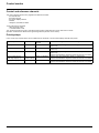


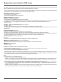
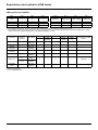
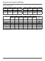
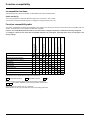

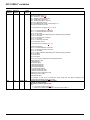
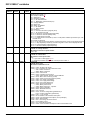
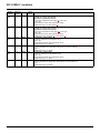
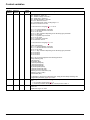
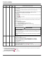
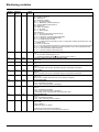
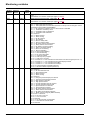
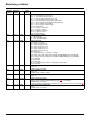
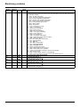
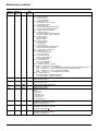
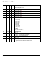
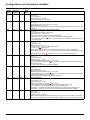
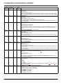
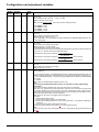

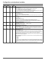
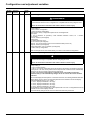
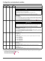
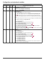
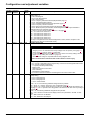
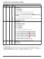
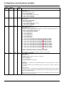
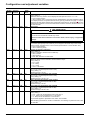
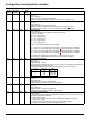
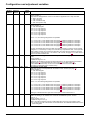
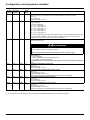
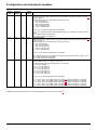
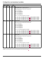
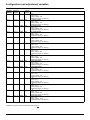
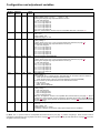
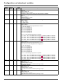
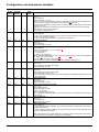
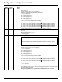
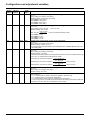
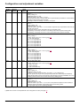
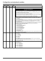
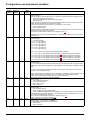
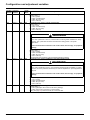
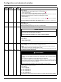
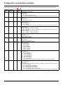
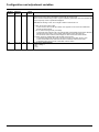
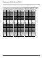
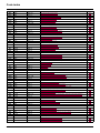
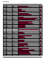
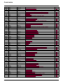
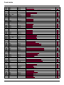

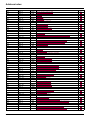
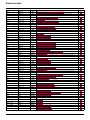
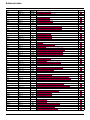


![[APPLICATION FUNCT.] (FUn-) menu](http://vs1.manualzilla.com/store/data/005791548_1-5d0d7ec5314f51691a1a65d93d033635-150x150.png)