1
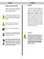
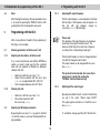
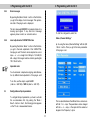
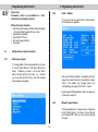
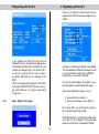
X-DVB-T / PAL twin
Operating Instructions
Illustration
Contents
Contents
Pictographs
1
Description . . . . . . . . . . . . . . . . . . . . . . . . . . . . . . . . Page 3
2
Installation of X-DVB-T / PAL twin card . . . . . . . . . Page 4
2.1
Cabling of X-DVB-T/PAL twin . . . . . . . . . . . . . . Page 4
3
Programming with the HE-Programming software Page 4
4
Basics for programming with the KC 3 . . . . . . . . . . Page 9
4.1
Structure . . . . . . . . . . . . . . . . . . . . . . . . . . . . . . Page 9
4.2
Order of Programming . . . . . . . . . . . . . . . . . . . Page 9
4.3
Store . . . . . . . . . . . . . . . . . . . . . . . . . . . . . . . . Page10
5
Programming with KC 3 . . . . . . . . . . . . . . . . . . . . . . Page10
5.1
Parameters of the
base unit / slot . . . . . . . . . . . . . . . . . . . . . . . . . Page10
5.1.1 Setting the bus address . . . . . . . . . . . . . Page10
5.1.2 Setting the slot . . . . . . . . . . . . . . . . . . . . Page10
5.2
Setting the RF-output parameters . . . . . . . . . . Page10
5.2.1 Setting RF-output frequency . . . . . . . . . . Page10
5.2.2 Switching off the output signal . . . . . . . . Page10
5.3
Setting the input parameters . . . . . . . . . . . . . . Page11
5.4
Editing the input parameters . . . . . . . . . . . . . . . Page12
5.4.1 Choosing a program . . . . . . . . . . . . . . . . Page12
5.4.2 Audio options . . . . . . . . . . . . . . . . . . . . . Page12
5.4.3 Manual program choise . . . . . . . . . . . . . Page12
5.4.4 Video options / test signals . . . . . . . . . . . Page13
6
Short overview of programming steps . . . . . . . . Page14
7
Technical Data . . . . . . . . . . . . . . . . . . . . . . . . . . . . . . Page15
X-DVB-T / PAL twin plug-in card
2
. . . . . . . . . . . . . . . . . . . . . . . . . . . . . . . . Page 3
Pictograms
1 Description
1
Pictograms and safety information
The X-DVB-T / PAL twin card is designed for the
transcoding of two digital terrestrial TV-programmes into standard PAL-signals within the
frequency range 47 – 862 MHz. It contains two
independent input demodulators and one
shared output converter. This means any two
terrestrial programmes can be converted in two
adjacent channels. Data Services as VPS or
Teletext can be switched on and off as well as
the generation of test signals. Each board has a
level control for level matching of the individual
plug-in boards to the same output level via KC 3
or HE-programming software.
Pictograms are symbols which have a defined meaning.
You will encounter the following pictograms in these
operating and installation instructions:
This symbol is used to warn about situations in which
there is a risk of fatal injury due to dangerous electrical
voltages or as a result of failure to comply with these
instructions.
This symbol is used to warn about various risks to
health, equipment/materials or the environment.
☞
Description
This symbol is used to indicate general information.
Recycling symbol: all of our packaging materials (cardboard packaging, package inserts, plastic film and plastic bags) can be fully recycled.
Please note:
Authorized and qualified personnel only, is allowed to change the plug-in modules. Before this,
the operating instructions, and especially the
security advises, of the V16 base unit have to be
read and followed. All works have to be done
according to the security standards DIN VDE
0701, part 1 and 200.
Electronic equipment is not household waste – in accordance with directive 2002/96/EC OF THE EUROPEAN
PARLIAMENT AND THE COUNCIL of 27th January 2003 on
used electrical and electronic equipment, it must be disposed
of properly. At the end of its service life, take this unit for disposal at a relevant official collection point.
3
1 Description
2
2 Pre-configuration
Installation of X-DVB-T / PAL twin card
The X-DVB-T/PAL twin module can be operated in the
input X-2 twin, X-5 twin, X-8 twin and V16 base unit.
After mounting the module, please re-check the correct fitting of the sockets.
2.1
Cabling of X-DVB-T/PAL twin
The X-DVB-T/PAL twin can be operated with a bridge
for the input signal. This means that the signal from
the loop-through output of Tuner A is bridged to the
input of Tuner B.
Tuner A and tuner B connected separately with input signal
3
Programming with the HEProgramming Software
After the installing, the X-DVB-T / PAL twin card can
be programmed via HE-Programming software. If it is
not possible to choose the X-DVB-T / PAL twin card
from the list in the „Overview of the base unit“, you
should check the settings at “Options” → “Favoured
plug-in cards. The card must be activated as below, to
appear on the list in the „Overview of the base unit“.
Input signal bridged from tuner A to tuner B
4
2 Pre-configuration
2 Pre-configuration
In the overview of the base-unit, you can set the output channels of the X-DVB-T / PAL twin card at “RFParameters”. This means those channels, in which
the, from the DVB-T bouquet selected, programs are
inserted to the cable network. The chosen channel is
always channel A. Channel B is automatically determined as adjacent channel of channel A.
After reading out the base unit, the X-DVB-T / PAL
twin card appears in the “Overview of the base unit“
on the used slot.
☞
Please Note:: Required Software version:
X-5 Basis twin:
4.00
X-8 Basis twin:
1.21
V16:
1.21
Programming software
4.90
If you now click on the “Details” button, a window
opens for configuring the card details. Here you can
make the relevant settings for the operation.
At the area „Input parameters“ you can set the input
channel, the bandwidth, the mode and the guard interval.
5
3 Programming with the HE programming software
3 Programming with the HE programming software
If you use the button “Check signal quality”, the C/N
and the Bit error ratio of the input signal of the card
will be displayed.
You can choose the program from the transponder
after a channel search, you are asked to do after programming the X-DVB-T / PAL twin card.
At the area “HF-Output parameter”, the output channel can be activated and deactivated. In addition you
can increase or decrease the Audio amplitude,
change the Audio-Mode (Mono, Stereo…), and the TV
standard (PAL or SECAM).
6
3 Programming with the HE programming software
3 Programming with the HE programming software
Following to the channel search, the list with the
included programs chooseable from the transponder
opens up automatically.
If you choose a multilingual transmitted program, you
have the possibily to select different audio-PIDs.
The program is chosen by clicking on it, without programming the card again.
7
3 Programming with the HE programming software
3 Programming with the HE programming software
But on the television screen you can see the error message for example „NO INPUT DATA“. This is why the
manual program search must be tested in the output of
the head end with TV-Set or measurement equipment.
If you click on “Options” in the window of the “Parameters of the Plug-in card”, the following window appears:
Changes are only written and stored into the Plug-in
card after clicking the button “Write Options“.
The level adjustment of the X-DVB-S/PAL twin card
can also be done via HE-programming software. For
this you just have to click on “Level control“ in the window “Parameters of the Plug-in card”.
With “Read Options”, the parameters programmed into
the card will be read out and displayed. These parameters are Data Services, Test lines or manual program selection.
Here you can (de-) activate data services as VPS or
Teletext if provided by the transmitter and fix the CNI
code hexa-decimal. Further on, there is the possibility to
switch on or off test lines, and to type in the line in which
the test line should be keyed in. The valid range for keying in test lines is between 17–28 and 330 and 341.
☞
Please note, that the testing lines are priorised, if the
same line is choosen for teletext and testing lines!
If you activate the manual program selection, and
you type in invalid PIDs, there is no error message in the HE-programming software!
8
3 Programming with the HE programming software
4 Fundamentals for programming with the KC 3
By pressing the cursor keys ← or → you get into the
menu for adjusting the parameters of the base unit,
and then to the
First of all you should push the button „Parameter
read“, to read out the already programmed state of
attenuation.
The next step is the correction of the attenuation in
0,5 dB – steps. To store the changed values press
„Parameter write“.
Programming of the specific parameters of the card
which consists of 4 lines. You can switch between
these lines with the ↑ and ↓ keys.
If you push the button „Restart cards“ in the window
„Details of the Plug-in card“, all Plug-in cards of the
base-unit will be restarted. This leads to a short-term
loss of vision. This is why you have to confirm the
restart.
Line 1:
type of card,
here X-DVB-T/PAL twin A/B Status OK
Line 2:
Choosing the input and (de-) activating
the ON-Screen-display
Line 3/4: RF – output parameters
The programming of the parameters is made via keypad or as stepwise change of pre-defined parameters
with the cursor ↑ or ↓.
4
4.1
Basics for the programming with the
KC 3
☞
Please note:
Input values must be complete!
4.2
Order of programming
1. Choose the Plug-in card (line 1)
2. Type in the output parameters of the
Plug-in card (line 3/4)
3. Adjust the connected TV-measurement device
on the programmed output frequency
4. Turn on the on-screen-display (line 2)
5. Type in the input parameters in the
on-screen-display
6. Switch off the on-screen-display (line 2)
Structure
After plugging the KC 3 handheld on the base unit, the
start menu appears. The software version is displayed. Please give this number to our customer service if you have questions regarding the
X-DVB-T/PAL twin card. To see this menu later once
again, you have to plug the KC 3 out and in again.
9
4 Fundamentals for programming with the KC 3
4.3
5 Programming with the KC 3
Store
5.2.1
The RF-output frequency can be adjusted in line three
with the input of the frequency value by keypad or in
line
four
with
the
stepwise
change
by
cursor keys ← or → (100-kHz-steps).
After finishing the data input, the new parameters have
to be stored by pushing the “OK/Store” button. After
pushing this button, the parameters are saved.
5
Programming with the KC 3
☞
After choosing the slot (chapter 4), the programming of
the Plug-in card can begin.
5.1
Choosing parameters of the base unit / slot
5.1.1
Adjusting the bus address of the base unit
•
•
•
5.2
The input will not be checked, this means that a
wrong input is stored after pushing the
“OK/Store” button without warning!
Select line 3 with the cursor keys ↑ or ↓
Adjust the bus address with the cursor keys
← or → in a range between 001 – 020, 241
Store changed addresses with „OK / Store“
5.2.2
Choosing the slot
•
•
Please note:
The adjusting of the output frequency should always
be done by choosing the channel in line 4. This
makes sure that the picture carrier has a frequency
according to the corresponding channel grid.
Therefore the frequency in line 3 is changed automatically with the changed output channel.
The output channel can be changed with the cursor
keys ← or →.
If you connect several base units with the ASTRO bus
system, you have to make sure, that the connected
base units are adjusted on different bus addresses
(delivery state 241).
5.1.2
Adjusting RF- output frequency
Switching off the output signal
By pushing the „Menü / Read“ – button in the third line,
you get to the option “Output signal On/Off”.
The output signal is switched on or off with the cursor
keys ← or →.
Select line 1 with the cursor keys ↑ or ↓
Choose the required slot with
the cursor keys ← or →
Adjusting the RF-output parameters
By pushing the cursor keys ↑ or ↓ you get into the third
or fourth line. Here you can insert the required RF-output parameters.
To activate the changes push the „OK / Store“ button.
10
5 Programming with the KC 3
5.2.3
5 Programming with the KC 3
Error messages
By pushing the „Menü / Read“ – button in the third line,
you get to the display of error messages. The operational state of the plug-in card is displayed.
The error message 00000010 for example stands for a
missing input signal. If any other error message
appears, please contact our customer service.
5.2.4
To start the configuration, select the
Menu „Channel Settings“
Level adjustment of X-DVB-T/PAL twin
by choosing the menu „Channel Settings“ with the „OK
/ Store“ – button. Then you get to the main parameters
of the plug-in card.
By pushing the „Menü / Read“ – button in the third line,
you get to the level adjustment of the X-DVB-T/PAL
twin plug-in card. The level can be adjusted via cursor
keys ← or → in a range from 0 dB up to 15,5 dB (0,5
dB – steps). All changes must be stored by pushing the
“OK / Store” button.
☞
Important note:
You should never compensate outgoing cable attenuation by different level adjustment of the plug-in card!
To do this, use the output coupler U-901
(order no.: 380 190) or VZN 8 (order no.: 380 191).
5.3
Configuration of input parameters
To configure the input parameters, you have to activate
the on-screen-menu first. By pushing the “Menü /
Read” – button in line 2, the following picture appears
on the TV set or measurement device.
The movement between the different lines can be done
with the ↑ or ↓ – keys. The parameters can be changed
with the ← or → keys, or the input with the numerical
keypad in the “Frequency” option.
11
5 Programming with the KC 3
☞
5 Programming with the KC 3
Please note:
Parameters, which are pre-defined on “auto”,
should only be changed by experts.
5.4.2
Audio – Options
If you now choose a program of the chosen bouquet,
the following menu appears:
Setting the input parameters:
• Type in the input frequency with the numerical keypad
or choose the input channel with cursor keys
• Adjusting the bandwidth
• Type in the FFT mode
• Choose the guard interval
• Tune again
5.4
Configuration of output parameters
5.4.1
Choosing a program
To change details of the output parameters, you have
to choose “Select Service” in the menu “Main Parameter”. Therefore you have to choose the “Select
Service” button with the cursor keys ↑ or ↓. Confirm
your choice with the “OK / Store – key. The following
picture appears (example):
Here you have the possibility to change the audio language, the volume, the audio mode and the configuration of the subtitle. Any changes have to be
confirmed by pressing the “OK / Store” – button.
by pressing the “Change Service” button you get back
to the service selection.
5.4.3
Manual Program Choice
If the requested station / program does not appear in
the list “Select Service” you have to choose the last
point “Manual PID”. Here you can choose a program
manually:
12
5 Programming with the KC 3
5 Programming with the KC 3
Please choose „Options“ in the start menu. The now
opened window offers the following configuration possibilities:
In this sub-menu, the video PID, audio PID and
Teletext PID have to be entered four-digit decimal.
The hexadecimal PID will be converted by the card
software and displayed next to the decimal PID. If
you choose a program like this and you type in
wrong PIDs, there will be no error message on the
OSD!
This error message will be displayed in the TV-Set,
for example „NO INPUT DATA“. These error messages can be faded out. For doing this, please read
chapter 5.4.4.
5.4.4
Activating or deactivating of Teletext (if transmitted),
VPS (if transmitted) and OSD error messages as well
as choosing the video standard (PAL or SECAM).
Furthermore you can activate a fixed CNI.
If you now choose the submenu „Test signales“ you you
have the pssibility to activate different test signals.
There are two different test signals to choose:
1. black picture (choose „Black“) or
2. vertical colored beams (choose „BAR 75“)
Video – Options / Test signals
By choosing „OFF“, you see the normal program in
the TV set after deactivating the OSD.
The X-DVB-T/PAL twin – card offers the possibility to key
in test lines. For the configuration of those test lines
please choose “Test Lines” in the submenu “Options”.
13
5 Programming with the KC 3
6 Short-overviev of programming steps
Startmenü (appears only once after plugging in the KC3):
ASTRO V16
Version 2,01
1 = deutsch
(next < >)
V16 Setup
VMS 616
yes
Power
A+B
Password
off
“ Menu / Read”
→
V16 Serie
Password
0000
Password OK Menu
New PW
xxxx
Choose Line 4
Password on
→ then “OK/Store”
with Cursorbuttons ← or → to Menu 1
Menu 1 — Choosing the slot / channel:
Several different test lines can be activated and deactivated. If you activate a test line you can choose the
line for keying it in. The valid range for keying in the
test line is between 17 – 28 and 330 – 341. Any changes have to be stored by choosing the “Store” button.
☞
Choose line 1 with Cursorkeys ↑ or ↓.
With Cursorkeys ← or → choose the channel
V16 Parameters
VMS-Input 11-14
Adress
241
Temperature 22°C
Important note:
If Teletext and test line are keyed in the same line, the
test line has priority. Then the Teletext will not be fed
in the network.
01:
Slot
no or unknown
Plug-in Card!
04: TDVBT/P A OK
Input
11
RF out 311,2 MHz
Channel
S 22
Menu 2 — Output parameters:
Choose line 3 with Cursorkeys ↑ or ↓
04: TDVBT/P A OK
Input
11
RF out
311,2 MHz
Channel
S22
04: TDVBT/P A OK
Input
11
Error
00000010
14
with “Menu / Read” key switch between
the submenus
04: TDVBT/P A OK
Input
11
RF out
on
04: TDVBT/P A OK
Input
11
Attenuat.
-3,5 dB
7 Technical data
Type
X-DVB-T/PAL twin
Order no.
330 594
COFDM-Demodulator:
Input freqency range
[MHz]
Input level
[dBµV]
47–862
58–85
IF input
[Ω]
IEC Jacks, 75
Return loss
[dB]
typ. 10
Level control
[dB]
35
[Ω]
IEC Jacks, 75
HF-Modulator
Connections
Output frequency
[MHz]
Output channels
Output level
47–862
C2–C69
[dBµV]
90–100
Intermod.-distance
[dB]
typ. 60
Return loss
[dB]
> 10
Spurios frequency distance
[dB]
typ. 60
TV-Standard
Video-signal to noise ratio
B, G (D/K on request)
[dB]
typ. 60
[° C]
0... +50
Common data
Temp.-range
15
82 274 400 GB 10 / 06
ASTRO Strobel
Kommunikationssysteme GmbH
Olefant 1–3
D-51427 Bergisch Gladbach (Bensberg)
Tel. 0 22 04 / 405-0
Fax 0 22 04 / 405 10
http://www.astro-kom.de