1
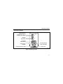
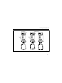
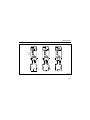
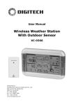
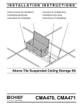
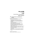
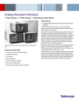
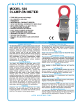
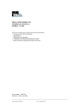
®
10
Multimeter
Users Manual
© 1991-2001 Fluke Corporation, All rights reserved. Printed in USA
All product names are trademarks of their respective companies.
10 MULTIMETER
m
m
Mk
SELECT
RANGE
OFF
VDC
VAC
600V
COM
+
acz06f.eps
10 Users Manual
Contents
Page
Read First -- Safety Information..................................................................
Contacting Fluke for Service, Accessories, or Parts ...................................
Standby Mode ............................................................................................
Operating Features.....................................................................................
Using Accessories ......................................................................................
Symbols ......................................................................................................
Using the Autorange and Manual Range Modes ........................................
Measuring Voltage......................................................................................
Testing Continuity And Measuring Resistance ...........................................
Turning the Beeper Off ...............................................................................
Testing Diodes............................................................................................
Maintenance ...............................................................................................
Replacing the Battery .................................................................................
Specifications..............................................................................................
2
3
4
5
6
6
7
8
10
10
12
14
14
15
1
10 Users Manual
Read First -- Safety Information
W Warnings and Cautions
To ensure that the meter is used safely and to avoid damage to the meter:
•
•
•
•
•
•
•
•
•
2
Use the meter only as described in this manual, or the protection provided
by the meter might be impaired.
Verify the meter’s operation by measuring a known voltage.
Do not use the meter if the meter or test leads look damaged, or if you suspect that the meter is not operating properly. If in doubt have the meter
serviced.
Replace the battery as soon as the low battery indicator (N) appears to
avoid false readings that can lead to shock and injury.
Turn off power to the circuit under test before cutting, unsoldering, or
breaking the circuit. Small amounts of current can be dangerous.
Do not apply more than 600 V rms between a terminal and earth ground.
Use caution when working above 60 V dc or 30 V ac rms. Such voltages
pose a shock hazard.
Keep your fingers behind the finger guards on the probes when using the
probes.
Disconnect the live test lead before disconnecting the common test lead.
Contacting Fluke for Service, Accessories, or Parts
This meter should be serviced only by a qualified service technician.
To order the 10 Series Service Manual (PN 900824), accessories, parts, or to get
other information, contact Fluke at one the phone numbers listed below:
1-888- 993-5853 in USA and Canada
+31 402-678-200 in Europe
+81-3-3434-0181 Japan
+65-738-5655 Singapore
+1-425-446-5500 in other countries
Visit Fluke’s web site at www.fluke.com.
Address correspondence to Fluke at:
Fluke Corporation
PO Box 9090
Everett, Washington 98206-9090
USA
Fluke Europe B.V
PO Box 1186
5602 BD Einhoven
The Netherlands
3
10 Users Manual
Replace Battery
Digital Reading
m
m
Mk
Manual Range
Continuity
Beeper Enabled
Measurement
Units
Diode Test
Note: Before using, peel off plastic lens protector, starting at any corner.
acz01f.eps
Figure 1. Display
Standby Mode
In Standby mode, the display goes blank to preserve battery life. The meter beeps and
enters Standby if it is LEFT ON BUT IS INACTIVE for more than 45 minutes. Press
any button to resume operation.
4
Operating Features
Operating Features
Toggle Between
Volts DC and AC, or
Continuity and Ohms
SELECT
Ranging
Operations
3-Position
Slide-Switch
RANGE
OFF
Volts DC/AC
Position
VDC
VAC
Common (Return) Jack
COM
Continuity/Diode
Test, and Ohms
600V
+
Input Jack
acz02f.eps
Figure 2. Operating Features
5
10 Users Manual
Using Accessories
When using accessories, put the slide-switch in the volts position.
For ease of reading, manually select the 4000 mV range. In the 4000 mV range, 1 mV
corresponds to 1 unit being measured by the accessory.
Symbols
W
B
F
t
N
6
Important Information; see manual
AC (Alternating Current)
DC (Direct Current)
Underwriters Laboratories, Inc
Battery. Low Battery on Display.
G
J
T
#
R
Diode
Earth Ground
Double Insulation
VDE (Verband Deutscher Electroniker)
Continuity Beeper
Using the Autorange and Manual Range Modes
Using the Autorange and Manual Range Modes
The range for each function determines the highest value the meter can measure. If
the range is too low, the meter displays OL (overload) and beeps. If the range is too
high, the display shows fewer digits of resolution.
The meter has an autorange and manual range mode. In autorange, the meter selects
the range automatically. The meter defaults to autorange when you turn it on. In
manual range, you lock the meter in a range.
To manually select a range:
1.
Press [Z] RANGE to lock the meter in the present range. Z is displayed.
2.
Press [Z] RANGE to step through the ranges. NOTE: The 4000 mV range, which
can only be entered in manual range, is convenient when using accessories.
3.
To return to autorange, press [Z] RANGE for 2 seconds (until Z is no longer
displayed), or change the measurement function.
7
10 Users Manual
Measuring Voltage
1.
2.
Insert the test leads in the jacks.
To select a voltage function, put the slide-switch in the middle position. (Figure 3.)
g
Press the [ ] SELECT button to toggle between dc and ac.
3.
Touch the probes to the test points, and read the display.
The meter beeps when OL (overload) is displayed.
8
Measuring Voltage
Volts DC
10 MULTIMETER
Volts AC
10 MULTIMETER
4
4
SELECT
SELECT
2
RANGE
OFF
RANGE
OFF
2
VDC
VAC
VDC
VAC
600V
COM
_
600V
+
+
COM
+
1
1
3
3
acz03f.eps
Figure 3. Measuring Voltage
9
10 Users Manual
Testing Continuity And Measuring Resistance
1.
Insert the test leads in the jacks, and turn off power to the circuit under test.
External voltage across the components causes invalid readings.
2.
Put the slide-switch in the continuity / ohms position (Figure 4). The meter selects
the continuity/diode or ohms function.
g
Press [ ] SELECT to toggle between the continuity / diode ( R G ) and ohms
(e) functions.
3.
Touch the probes to the test points.
In ohms, read the resistance on the display.
In continuity test, the beeper sounds continuously if continuity exists (resistance
<25 Ω). Opens and shorts longer than 250 µs are detected.
Turning the Beeper Off
To disable beeper functions, press and hold down [Z] for 2 seconds while turning the
meter on.
10
Turning the Beeper Off
Continuity Test
Resistance
10 MULTIMETER
10 MULTIMETER
4
SELECT
2
SELECT
2
RANGE
OFF
SELECT
RANGE
RANGE
OFF
VDC
VAC
OFF
VDC
VAC
600V
COM
10 MULTIMETER
4
k
VDC
VAC
600V
+
COM
600V
+
1
COM
+
1
3
3
Short
Open
acz04f.eps
Figure 4. Continuity Test and Resistance Measurement
11
10 Users Manual
Testing Diodes
1.
Insert the test leads in the jacks.
2.
Put the slide-switch in the continuity / ohms position. The meter selects either the
continuity / diode ( R G ) or ohms (e) function.
g
If ohms is selected, press [ ] SELECT to toggle to the continuity/diode function.
To toggle the beeper on or off in continuity/diode test, press [Z} RANGE. When
the beeper is enabled, R is displayed.
3.
Touch probes to the diode (Figure 5A). A forward-voltage drop of about 0.6 V
(typical for a silicon diode) causes the meter to beep once.
4.
Reverse probes (Figure 5B). If the diode is good, OL is displayed.
If the diode is shorted (Figure 5C), the beeper sounds continuously in at least one
direction.
If the diode is open, OL is displayed in both directions.
12
Testing Diodes
10 MULTIMETER
2
10 MULTIMETER
10 MULTIMETER
SELECT
SELECT
SELECT
RANGE
RANGE
RANGE
OFF
OFF
VDC
VAC
OFF
VDC
VAC
600V
VDC
VAC
600V
+
COM
COM
600V
+
+
COM
1
3
A
4
B
C
acz05f.eps
Figure 5. Testing Diodes
13
10 Users Manual
Maintenance
W Warning
To avoid electrical shock or damage to the meter, do not get water inside the
case, and remove the test leads and any input signals before opening the case.
Wipe the case with a damp cloth and detergent.
Do not use abrasives or solvents.
Replacing the Battery
W Warning
Replace the battery as soon as the low battery indicator (
false readings that can lead to shock and injury.
N
) appears to avoid
To replace the battery:
1.
Turn the meter OFF and remove the test leads from the meter.
2.
Remove the four screws from the back of the meter and lift off the front.
3.
Remove the battery and replace it with a 9 V battery (NEDA 1604 or IEC 6F22).
14
Specifications
Specifications
This meter complies with Part 15 of FCC Rules. Operation is subject to the following
conditions:
1.
This meter may not cause harmful interference.
2.
This meter must accept any interference received, including interference that may
cause undesired operation.
Accuracy is specified for a period of one year after calibration, at 18 °C to 28 °C (64 °F
to 82 °F) with relative humidity to 90 %.
AC conversions are ac-coupled, average responding, and calibrated to the rms value
of a sine wave input. Accuracy Specifications are given as:
+/- ( [ % of reading ] + number of least significant digits ] )
15
10 Users Manual
Maximum Voltage Between any
Terminal and Earth Ground
Display
Operating Temperature
Storage Temperature
Temperature Coefficient
Relative Humidity
Battery Type
Battery Life
Shock, Vibration
Size (H x W x L)
Weight
Safety
EMI Regulations
16
600 V rms
3 3/4-digits, 4000 counts, updates 4/sec
−10 °C to 50 °C
−30 °C to 60 °C indefinitely (to −40 °C for 100 hrs)
0.1 x (specified accuracy) / °C (<18 °C or >28 °C)
0 % to 90 % (−10 °C to 35 °C);
0 % to 70 % (35 °C to 50 °C)
9V, NEDA 1604 or IEC 6F22
Alkaline, 650 hrs continuous;
Carbon-zinc, 450 hrs continuous
1 meter shock. Vibration per MIL-T-28800D for a Class 3
Instrument
1.35 x 2.75 x 5.55 inches; (3.46 x 7.05 x 14.23 cm)
10 oz (286 g)
Complies with Protection Class II requirement of UL1244,
ANSI/ISA-S82, CSA C22.2 No 231, and VDE 0411, and
IEC 1010 overvoltage CAT III. CAT III instruments are
designed to protect against transients in fixed-equipment
installations at the distribution level.
Complies with FCC Part 15, Class B, and VDE 0871B.
Specifications
Function
Range
Resolution
Accuracy (50 to 400 Hz)
VB
4000 mV *
4.000 V
40.00 V
400.0 V
600 V
1 mV
0.001 V
0.01 V
0.1 V
1V
+/- (2.9 % + 3)
+/- (2.9 % + 3)
+/- (2.9 % + 3)
+/- (2.9 % + 3)
+/- (2.9 % + 3)
VF
4000 mV *
4.000 V
40.00 V
400.0 V
600 V
1 mV
0.001 V
0.01 V
0.1 V
1V
+/- (1.5 % + 2)
+/- (1.5 % + 2)
+/- (1.5 % + 1)
+/- (1.5 % + 1)
+/- (1.5 % + 1)
Ω
400.0 Ω
4.000 kΩ
40.00 kΩ
400.0 kΩ
4.000 MΩ
40.00 MΩ
0.1 Ω
0.001 kΩ
0.01 kΩ
0.1 kΩ
0.001 MΩ
0.01 MΩ
+/- (1.5 % + 2)
+/- (1.5 % + 1)
+/- (1.5 % + 1)
+/- (1.5 % + 1)
+/- (1.5 % + 1)
+/- (1.9 % + 3)
RG
2.000 V
0.001 V
+/- (1.5 % + 2) **
* The 4000 mV range can only be entered in manual range mode. Use the 4000 mV range with
accessories.
** The beeper is guaranteed to come on at <25Ω and turn off at >250Ω. The meter detects opens or
shorts of 250 µs or longer.
17
10 Users Manual
Input
Impedance
(Nominal)
Common Mode
Rejection Ration
(1 kQ Unbalance)
Function
Overload
Protection *
VF
600 V dc
>10 MQ <100 pF
50 Hz or 60 Hz
100 dB @ dc @
50 or 60 Hz
VB
600 V rms
>5 MQ <100 pF
(ac-coupled)
>60 dB, dc, 60 Hz
NA
Open Circuit
Test Voltage
Full Scale Voltage
Short Circuit
Current
Ω
To 4.0 MΩ
G
600 V rms
< 1.5 V dc
600 V rms
2.4 to 3.0 V dc
* 3 x 10⁶ V Hz Maximum
18
<450 mV dc
Normal Mode
Rejection
>50 dB @
50 or 60 Hz
40 M Ω
<1.5 V dc
2.400 V dc
<500 µA
0.95 mA typical