1
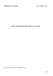
JAD X-Tract (Extreme)
Measurement and automation software platform.
Version 1.0.3
This document describes what X-Tract Extreme does
and how to use it.
X-Tract Extreme
User Manual
Table of Contents
Cover Page...........................................................................................................................................1
In a nutshell..........................................................................................................................................3
Supported Hardware........................................................................................................................3
Notable Features..............................................................................................................................3
Installation............................................................................................................................................5
Using X-Tract Extreme........................................................................................................................6
Run X-Tract and Login....................................................................................................................6
Configuration...................................................................................................................................6
Administrator configuration........................................................................................................6
Setup Hardware.........................................................................................................................10
Setup Test Templates.................................................................................................................20
Running a test................................................................................................................................29
Running a Report...........................................................................................................................37
Viewing a saved file......................................................................................................................40
Logout and exit X-Tract Extreme.......................................................................................................43
Contact Information...........................................................................................................................44
X-Tract Extreme User Manual Version 1
Page 2/47
X-Tract Extreme
User Manual
In a nutshell
X-Tract Extreme is a generic engineering software platform that measures, stores,
displays, and controls based on the measurement of physical signals such as;
Speed
Torque
Power
Temperatures
Pressures
Fuel flow
Air flow
Angle
Electrical power
Ambient conditions
Vibration
Acoustics
Emissions
Oil analysis
Position
PV diagrams
Human entry
CAN bus information
Reporting on signals or mathematical derivatives thereof.
Supported Hardware
X-Tract Extreme is designed to read from and write to several different types of hardware
simultaneously:
1. National Instruments DAQ devices;
2. National Instruments Fieldpoint devices;
3. National Instruments network based Shared variable devices (e.g. CompactRio
scan engine)
4. Devices supporting modbus over Ethernet protocol;
5. Devices supporting the proprietary JADbus protocol (similar to modbus);
6. Devices that support serial communication;
7. Norma, Newtons Fourth, Infratek, Power analysers;
X-Tract Extreme User Manual Version 1
Page 3/47
X-Tract Extreme
User Manual
8. Many others (custom interfaces can also be created on request).
Notable Features
1. Software can be precision timed if suitable hardware (e.g. a DAQ device) is
present, allowing for accurate time based calculations such as inertial energy or
pressure volume diagrams;
2. It can deal with high-speed data (tested with 4 channels at 50HKz each), and can
be used for vibration analysis via Fourier transforms and power spectrum.
3. Audible alarms for out-of-range channels can be configured;
4. Provisions are made for calculations to be performed on channels e.g. Power can
be calculated based on speed and torque. Variables to these calculations can
include current data or historical data (including various statistical functions);
5. The software has built-in functions to calculate;
•
Gear ratios;
•
Power correction factors to compensate for ambient conditions;
•
PID based control, JAD's specially designed additional calculations for
improved stability, as well as bump-less transfer of control process variable;
•
Instantaneous position or angle based values.
•
Spectral analysis of vibration data, including feature extraction based on
currently measured speeds.
6. Data can be averaged over a pre-defined window to compensate for electrically
noisy signals,
7. Live graphical displays can represent data as;
•
time-based charts;
•
Instantaneous snapshots of high-speed data;
•
channels plotted against one another, this can include compatible data
loaded from a previously recorded file.
X-Tract Extreme User Manual Version 1
Page 4/47
X-Tract Extreme
User Manual
Versions
X-tract has the following version configurable via the licence key,
Version
Measure
Control
Base
x
PID
x
x
PID scripted
x
x
Run Scripts
Analysis
Reports
x
X-Tract Extreme User Manual Version 1
x
x
x
x
x
Page 5/47
X-Tract Extreme
User Manual
Installation
Steps:
1. Insert the DVD disc provided by JAD Systems, labelled X-Tract Extreme into the
DVD ROM of the computer in use;
2. Microsoft Dot Net Framework Version 3.0 is a requirement to use X-Tract Extreme,
if it is not already installed on the computer , make sure that it is installed before
installing X-Tract Extreme;
3. Open My Computer, then the DVD ROM, in this directory there are 2 folders called
“X-Tract Extreme Prerequisites” and “X-Tract Extreme Setup_?_?_?_?”, as well as
OpenOffice and Convert. First install the prerequisites; (Note: the prerequisites
comprises the software environment required to run X-Tract Extreme)
4. In the “X-Tract Extreme Prerequisites\Volume” folder double-click the “setup.exe” to
run the installation, Follow the installation steps;
•
On Destination Directory window, click next;
•
Start Installation window, click next;
•
Wait until the setup has finished installing the prerequisites;
•
On Installation Complete, click finish.
5. Go back to the DVD ROM directory and navigate to “X-Tract Extreme Setup_?_?_?
_?\Volume” directory and double-click the setup.exe to run the installation of XTract. Follow the installation steps. (Note: this installs the actual X-Tract Extreme program)
•
On Destination Directory window, click next;
•
Start Installation window, click next;
•
Wait until the setup has finished installing the prerequisites;
X-Tract Extreme User Manual Version 1
Page 6/47
X-Tract Extreme
User Manual
•
On Installation Complete, click finish.
•
X-Tract Extreme should now be installed properly, and placed an icon on the
desktop.
Using X-Tract Extreme
Run X-Tract and Login
1. After installing X-Tract Extreme, there will be an icon on the desktop;
2. Clicking it should start X-Tract Extreme (depending on the speed of the pc, this may
take a few moments);
3. On the resulting main menu, click the “Login” button, enter a user name and
password and click the “login” button;
4. This will enable certain main menu buttons depending on the permissions given to
your account.
Configuration
Systems integrator configuration
X-tract Extreme should be run the first time by an administrator, the following is for
administrator use only, a normal user will not have access to the configuration functions.
After installing X-Tract Extreme, the system needs to be configured based on a set of
X-Tract Extreme User Manual Version 1
Page 7/47
X-Tract Extreme
User Manual
requirements, and performance of the computer on which X-Tract Extreme will run.
1. Click the “Admin” button from the main menu;
2. The resulting window provides for three types of information;
•
Job information template, this is a template of what will be provided to the
user to complete each time a test is run. Using the reserved words $date and
$time would put the actual date or time in the field at the time the test is run;
(Note: these fields will be displayed on the report, not as $date, but in a date format
e.g. 2013-05-06).
1. Enter information in the left column, and the corresponding values in
the right column.
•
Runtime, specifies hardware timing sources and rates, it also specifies which
tabs would be seen by a normal user when they run a test;
X-Tract Extreme User Manual Version 1
Page 8/47
X-Tract Extreme
User Manual
1. Max Channels – Specifies the maximum amount of channels to read;
2. HW Loop Rate – the time interval (in milliseconds) that the hardware
sends the acquired data up to the software;
3. The GUI loop rate - (in milliseconds) should be an integer multiple of
the hardware loop rate (in milliseconds);
4. Save Rate – The rate at which X-Tract Extreme saves the required
data to the TDMS file;
5. Timing Source – This Refers to the hardware that is used for the
timing; (e.g. Compact DAQ is a very accurate timing source, whereas the
PC is not a very good timing source)
6. History Length – A non zero history length is only required if
calculations need to be performed on historical data, or if averaging of
channels is required;
7. JADBus Server port – This is the TCP IP port used to connect to by
JADBus;
8. Default Averaging – The default averaging duration (in seconds) is
applied only if a channel's averaging time is -1; (Note: See Setup Test
Templates for more information)
9. Alarm Colours in text fields – Changes the colour of text fields when
an alarm is triggered;
10. Colour Ramps – This allows different styles of colour ramps to be
displayed based on alarm values; (e.g. 0 – 5 is green, 5-8 is orange
and 8-10 is red)
11. Default Report – Specifies the default TDMS file to record the acquired
data to, if left blank, then the user will be prompted for a report to run;
X-Tract Extreme User Manual Version 1
Page 9/47
X-Tract Extreme
User Manual
12. Force Job Information – Makes sure that the user currently using XTract Extreme, cannot stop and save the currently running test without
entering the job information;
13. Force Specification – Makes sure that the user currently using X-Tract
Extreme, cannot stop and save the currently running test with out
entering the Specification of the object being tested;
14. Force Marks – Makes sure that the user currently using X-Tract
Extreme, can not stop and save the currently running test without
taking any marks;
15. Visible Tabs – A user can select the tabs that are visible when running
a test template.
•
Users tab contains configurations for the user names, passwords and their
roles in the system;
1. Only Administrators can change the permissions given to a user
account;
2. To change user permissions, login as an administrator, click the admin
button and select the users tab, in this tab select user type and choose
the desired option, then click the save button.
•
License tab, this contains the license information, the licensing will be
done/given by a JAD Systems;
1. The only important options here are save license which is used to,
license the copy of X-Tract Extreme,and paste license,which is used if
the licensing for the computer in use is done over the phone or email;
➢ Click on save licence, notice Product (the name of the product),
PC Serial Number(the serial number of the computer in use),
and Key ( the registration key unique to the computer in use,
this will be provided by JAD Systems);
X-Tract Extreme User Manual Version 1
Page 10/47
X-Tract Extreme
User Manual
➢ To paste a license, that has been sent, just click the paste
license button, copy the text (of the license that has been
received) and paste it in the provided text area and click OK.
•
The Events tab is used purely as a record of actions performed; (e.g. loading
and saving of these settings)
•
Click the Save button when all desired information in the administrator
configuration has been completed, click the save button to save all the
changes made. Then click the done button to close the window, the X-Tract
Extreme Main Menu should now be visible.
Setup Hardware
To start configuring the hardware, click the setup hardware button on the X-Tract Extreme
Main menu. This should bring up a new window called Setup HW, the first tab will be
selected .
1. Data Intermediaries, are pre-named locations for storage of values to be output, or
used as parameters to built-in modules that perform calculations. The order of the
variables is from left to right; (Note: DI names can be named anything you can think of)
•
Click on the load button to load a hardware template (Note: Typically named
hw.hw);
•
to create a new data intermediary, click on the text field and enter the name
of the data intermediary (DI) name;
•
When finished entering all desired Data Intermediaries, click the “Apply”
button before selecting the modules tab.
2. Modules, Each module represents interaction with physical hardware or built-in
logic functions. Communication with any of the following modules is possible; (Note :
to Enable a module, click on the round button to the left of the module name, it should turn blue,
now click the button next to it, to setup the module.)
X-Tract Extreme User Manual Version 1
Page 11/47
X-Tract Extreme
User Manual
•
Hardware ;
1. CRio – interaction with a National Instruments CompactRio via the
scan engine software. This module is typically configured by ensuring
that the Crio is available on the network and using the search function;
Output index
Input index
Input from Physical
modules plugged
into the CRIO
chasiss
Output to physical
modules plugged into the
CRIO
•
Input index – is used to specify the first test template channel
that would be read by the first input, the channels read after,
are in order; (Note: this will typically be 0)
•
Inputs – are the actual data channels being read from the
hardware; (Note: these inputs reference actual channels, on the
hardware, these channels are then output to the test template(when
run, through the data intermediaries.)
➢ In the inputs table click on a drop down box and select
the installed modules/channels to be read from the
Compact Rio. (Note: these modules should be installed on
the hardware side and should already be configured in MAX.)
•
Output index – Specifies which data intermediary would be
output to the first output in the test template; (Note: this is usually
the same as input index, but does not need to be)
•
Outputs – is the raw data read from the hardware being output
on the test template when a test is run. (Note: The outputs are
X-Tract Extreme User Manual Version 1
Page 12/47
X-Tract Extreme
User Manual
references of the inputs, and are used in calculations and formulas in the
channels configuration, later in this manual)
➢ In the outputs table do the same as for the inputs,
however this time select modules that data needs to be
output/written to instead of read from.
2. JADBus – a proprietary TCP/IP protocol. The input and output parameters
are each composed of (from left to right), first value to read, and number of
values after to read;
First Channel to read
Amount of channels to read after
start channel
The first channel to write to
connected devices
The number of
channels/values to write
to connected device after
the first channel
•
Input index – Refers to the first channel number into which
values read from JADBus are placed;
•
Output index – refers to the first data intermediary that will be
used for output to JADBus devices;
•
Sets – specify sets of JADBus variable to read;
➢ IP Address – The IP address of the hardware to connect
to an read channels/values from;
➢ Port – The port to connect through to the hardware to
read channels/values from;
➢ Inputs – The channels to be read from the connected
source;
➢ Outputs – the values written back to the hardware by the
software. (e.g. X-Tract Extreme will write values back to
the hardware for control purposes)
3. CDAQ – interaction with National Instruments DAQ devices through
tasks configured in Measurement and Automation Explorer (MAX);
X-Tract Extreme User Manual Version 1
Page 13/47
X-Tract Extreme
User Manual
Input index
Input tasks
Output tasks
•
Input index – Specifies the first test template channel to read to.
The channels from the MAX tasks will be read in order, and
placed at the input index entered, up to the last available
channel;
•
Output index - Specifies the data intermediaries to output to in
order;
➢ Click on the drop down list and select a Data
Intermediary. (Note: The list of Data Intermediaries are
ordered, meaning the first item in the list is position 0, the
second position 1,the third at position 2 etc.)
•
Input Tasks – (MAX) tasks that accept input from the hardware;
➢ Click on the drop down and select a task to read data
from (Note: These tasks should already have been
configured in MAX for a cDaq, also notice that input
tasks is a list of tasks, so that more than one task can be
used to read data).
•
Output Tasks – (MAX) tasks that output data, that was read
from the hardware.
➢ Click on the drop down list and select a task to output
data to.(Note: These tasks should already be configured
in MAX for a cDaq, also note that output tasks is a list of
tasks, so that data can be written to more than one task)
4. cDAQ Frequency – is primarily use for frequency detection on a digital
input; (e.g. RPM)
X-Tract Extreme User Manual Version 1
Page 14/47
X-Tract Extreme
User Manual
Input index
DAQmx task Name
•
Input index - Specifies the first test template channel to read to;
•
DAQmx Task Name – Refers to a cDAQ task configured in
MAX;
➢ This task should already be configured/created in MAX,
the task would have been configured for speed pick-up.
Click on the drop down and select the appropriate task.
(Note: cDaq frequency is used primarily for speed pick-up and
is recommended when detecting speed)
5. Field point – Interaction with National Instruments field point devices
through pre-configured IAK file; (Note: The IAK file mentioned, is a file
stored on the computer in use, and uploaded through MAX to the field point
device, this file contains the configurations of modules attached to the field point
device)
The physical fieldpint module
An attachment module that
reads actual value/channels
from hardware
A configured channel in the
attatchment module.
•
IAK File name – Load the IAK file from the X-Tract Extreme
configuration folder; (Note: If it does not exist, then a new IAK file will
have to be created in MAX)
➢ Use the auto complete button to specify an IAK file, this
will read items in alphabetical order.
•
Input index - Specifies the first test template channel to read to
X-Tract Extreme User Manual Version 1
Page 15/47
X-Tract Extreme
User Manual
All channels after will be read in order;
•
Inputs – The values read from the hardware. And displayed
when running a test; (Note: these values are scaled to represent the
correct type of data)
•
Output index – Refers to the data intermediaries to output to the
field point device for control purposes;
•
Outputs – the values output to the to the filed point through
Data Intermediaries for control.
6. DABIOn – (Data Acquisition Board for input and output)Dabion is a
JAD Systems Proprietary serial protocol for boards designed for one
or more inputs and/or outputs. The values to enter would be provided
with specific equipment;
7. Norma – Power analyser;
X-Tract Extreme User Manual Version 1
Page 16/47
X-Tract Extreme
User Manual
•
8. AVL Blow By – this tab is used to configure communication with an
AVL Blow-by meter;
•
Replay;
1. TDMS – is used to allow a user to replay a previously recorded TDMS
file.
X-Tract Extreme User Manual Version 1
Page 17/47
X-Tract Extreme
User Manual
•
•
File name - the name of the TDMS file to load when running a
report;
•
Start time – Keeps track of the time that the test started.
Running;
•
Stop time – Records the time that the test was stopped;
•
Replay Action – None, no replay, Play Again, replay.
Data Intermediaries;
1. PID III – This calculates an appropriate output based on a measured
process variable (e.g. speed) and desired set point for the that
variable;
•
The usage of this module requires special training. The gains
specified in this module can be “tuned” while running a test. The
internals index is used during tuning to output some of the
internal calculations of the module to channels for use in better
understanding the behaviour of the system being controlled.
X-Tract Extreme User Manual Version 1
Page 18/47
X-Tract Extreme
User Manual
(Note: Several PID loops can be configured)
2. Bumpless Transfer (Tfer) – This ensures that the transition of PID
control from one process variable to another is as smooth as possible;
(e.g. transition from speed based control to torque based control)
•
Each PID controller ( Usually at most one) may control several
process values. The bump less transfer ensures that should the
control mode of a PID controller change, the desired set point
of that controller is the currently measured process value;
•
Mode DI – This refers to the control mode usually the control
modes are configured as data intermediaries with the following
values; (Note: are usually set to the following.)
➢ 0 = Coast (no braking force);
➢ 1 = Speed control;
➢ 2 = Torque control;
➢ 3 = Power control;
➢ 4 = Direct control.
•
Set Point DI – is specified by a user currently running a test on
the system;
•
Dial – Refers to a dial linked to a data intermediary;
•
Sources – Sources is a list of different control modes, and their
process values for each control mode.
3. Gear Ratio – This allows a user to calculate the gear ratio by
specifying the engine RPM that results in the measured wheel speed;
X-Tract Extreme User Manual Version 1
Page 19/47
X-Tract Extreme
User Manual
4. Ambient Corrections – This module uses ambient air pressure,
temperature and barometer readings to calculate a power correction
factor to apply;
5. Output Sel – is used to route output to a specific location based on
certain criteria of another channel;
3. Event Log, this tab is used to record actions performed by the user currently
using/configuring the software.
X-Tract Extreme User Manual Version 1
Page 20/47
X-Tract Extreme
User Manual
Once the hardware template has been configured as desired, make sure to save the
template. (Note: You may overwrite an existing one if necessary – it is seldom the case that
multiple hardware templates are required in a system.)
Setup Test Templates
1. Specifications;
•
A table of specifications that can be entered, These are typically for a user's
reference during the execution of a test. Using the table of specifications
typically implies one template for each product type being tested,
Specifications can be saved and loaded after run-time;
1. Click on an empty text field and enter a desired value; (e.g. Engine
type, Engine Name, etc)
2. Click on the next Tab “Manual Entry”.
2. Manual Entry;
X-Tract Extreme User Manual Version 1
Page 21/47
X-Tract Extreme
User Manual
•
Manual Entry template. This is a table to be completed when a test is
executed. Values entered in this table are typically measurements taken by
hand, and entered manually. The table would be saved together with other
data acquired during execution of a test, and could then form part of a report.
1. Click on an empty text field and enter the desired values.
3. Hardware;
•
A hardware template specified by the system integrator is referenced by file
name. The name stored is relative to the X-Tract Extreme configuration
directory.
1. Click the browse button and select the hardware template; (Note: the
hardware template will in most cases be named hw,hw)
2. Click on the save button note that X-Tract Extreme won't save an
empty template and will tell the user to either create channels(covered
in the next section) or to load an existing template;
3. In the hw parameters box, click on the module text field an select the
module in use, click on when and select the desired selection, type in
the parameter name and then the value.
4. Channels;
X-Tract Extreme User Manual Version 1
Page 22/47
X-Tract Extreme
User Manual
•
Channels;
1. Measurement Channels - A measurement channel is data acquired from
one of the sources specified in the hardware template;
•
To add a channel click add, X-Tract Extreme should have
added an unnamed channel. Now click on the name, erase the
current text, enter the desired channel name (e.g.
speed,torque), then click apply, the unnamed text in the left has
now changed to what was entered.
2. Dials, Switches and Constants – are used for human controlled
values in the system, such as control set points;
•
Constant control category, specifies which control on the user
interface is toggled by the user to set the channels value;
•
Initial value, specifies the value the channel will take on at the
start of a test.
➢ To add a channel, do the same as for measurement
channels. Notice that the No Probe field, is not I this tab,
and there is a new field called “Constant Control
Category”.
3. Advanced Channels - Advanced channels allow a channel to be
created based on the value of a data intermediary or other channel;
•
Advanced Control Category - pecifies the type of source that is
provided to the channel with its value; (Note: This can be 1)
another channel 2) a data intermediary or 3) an external program.)
•
Do the same as Measurement channels to add a channel.
4. Generated Channels;
X-Tract Extreme User Manual Version 1
Page 23/47
X-Tract Extreme
User Manual
•
•
Formula - the formula that calculate the value of the channel
Parameters to the formula;
•
Again, to add a channel do the same as for measurement
channels.
To Add Channels;
1. Firstly, if a template already exists, Click the load button, and select a
template, once it is loaded, we can move on;
2. Click the add button, X-Tract Extreme will create a new unnamed
channel in the list to the left;
3. Click on the name field to the right of the list of channels, change it to
the desired name;
4. In the units text field, enter the data type; (e.g. kPa,Nm,kW,RPM,A,V)
5. In the format field, ether leave it blank or enter “%.2f”; (Note: Refer to
the list below for more information on the format field, also check for case
sensitivity)
6. The reduction field, this will usually be set to mean(average), but can
be set to, Min, Max, and Rms as well;
7. Ref - this field is used as a reference in scripts and generated
channels for calculations and formulas; (Note: when referencing a channel
by reference, put the name in square brackets (e.g. ([rpm]*[kw])/9549.3))
8. Range - set the Max field to the highest possible value that the data
read could reach. The set the Min field to the lowest possible value the
data could reach;
9. Alarms - to set alarms, the low field should be set to a desired low
point, when the channel values are equal to or less than the low
setting, an alarm will be triggered, the same applies to High, High
warn and low warn. The colour for each range/point can be changed
to the right of the fields; (Note: if no alarm is desired set the fields to inf for
high and high warn and -inf for low and low warn.)
10. Output to DI - if set will place the channel's value into the specified
data intermediary every time the channel's value changes;
11. Save Type - select the type that should be present in the report; (Note:
refer to the list below for more information on save type.)
12. Averaging Time - enter a value with no decimal places. (e.g. 1, 2, 3, 4,
-1)
•
Channels have;
X-Tract Extreme User Manual Version 1
Page 24/47
X-Tract Extreme
User Manual
1. A unique name; (Note: channel names must not be duplicated)
2. Units; (e.g. V, A, Nm,kW,mBar)
3. Format - leaving this blank will result in the default formatting of 1
decimal place. When saving data , the exact value measured is saved
respective of this format specifier. Typical formats are “%.xf” where x is
a number that specifies the decimal places; (e.g. 2 for 2 decimal
places “%.2f”)
4. Range - these values are used when the channel is displayed on a
gauge, and reflect to highest and lowest possible values on the gauge;
5. Alarms - typically set to -inf or inf (Note: inf = infinity), which state that
an alarm will never go raised, however if the high and low alarm
values are an actual value not set to inf or -inf, an alarm will be raised
when the channel values go out of this range;
6. Output to DI - when a data intermediary is selected here, then when
the channel value changes, the named data intermediary will be set to
the channel value;
7. Save Type - This specifies what value to of the channel will be saved.
Sometimes channel values are read in chunks of up to several
thousand in short time intervals. A user can specify that the min,
min,mean, all or none of these values are saved to the TDMS file;
8. Averaging Time - this specifies a windowed average for the channel
value. Used typically to smooth a noisy signal;
9. Ref - this value depends on the order in which the channels appear in
the template, and is used when referring to the channel in formulas
and scripts.
5. Marks;
•
Marks - these are named points in time, which are used at reporting time,
These tie closely with customer-specific procedure followed for
X-Tract Extreme User Manual Version 1
Page 25/47
X-Tract Extreme
User Manual
performing tests. (e.g. An engine builder could run the engine at “10%”
load “20%” load “30%” load, etc. up to “100%” load, and take a mark
when the conditions have been met . During the report one could extract
the Speed, Torque and power at those respective points in time)
1. Click on one of the greyed out text fields and enter the desired name
for the set point in the desired order. (Note: When running a test, to take
marks at the desired/required point in time, press the space bar.)
6. Gauges;
•
Gauges - this allows a user to specify where (by default) a channel appears
on the user interface.
1. Click on the combo boxes to select a channel to display/view. (Note:
the channels refer to the channels created earlier in the channels tab)
7. Electrical;
•
The Electrical tab, This module is used to display any information on current
X-Tract Extreme User Manual Version 1
Page 26/47
X-Tract Extreme
User Manual
channels/values being read from the hardware, and was original designed for 3
phase power analysis.
8. Dial Labels;
•
Dial labels - allows a user to replace numerical values on a dial with a textual
caption. (e.g. Instead of having control modes labels 0, 1 , 2, 3 and 4 we
could have then labelled as “Coast, Speed, Torque, Power and Direct”. Only
dial number 2 supports this feature.)
1. to display channel values when running a test, click on the Dial Labels
tab and select a dial number from the drop down list, and enter a
label/labels for that dial.
9. X-Script;
X-Tract Extreme User Manual Version 1
Page 27/47
X-Tract Extreme
User Manual
•
X-Script is a basic program that controls user inputs, waits for events to
happen and takes marks. The usable commands are documented on the
right hand portion of the screen.
1. Before writing a script take a look at the help provided, just select a
key word from the drop down list to view its function; (e.g.
#comment, :label.)
2. Then once a user feels the he/she is familiar enough with the X-script,
click on the white space and start writing a script.
10. Extra Processing;
•
Tachometer – the tachometer is used to derive a frequency based on a
sinusoidal or square wave analogue input.
•
Configure vibration – Allows a user to extract vibration features from the
system, such as power-in-band calculation.
11. Charting and Graphing plots;
•
This tab “Charting Plots” is used to configure the channels that a user needs
to plot against a graph or chart. Charts add to the graph displayed over time,
X-Tract Extreme User Manual Version 1
Page 28/47
X-Tract Extreme
User Manual
while a graph displays a snapshot of instantaneous high speed data. (Note:
charting, graphing is disabled by default to enable charting, toggle the enable button
on, it will turn green, then select the channels in the drop down box to be plotted.)
12. XY Plots;
•
This tab “XY Plots” is used to plot channels on a XY plot, a XY chart plots
one or more channels against another channel, plot points are added each
time a mark point is taken;
•
This is disabled by default and can be enabled by selecting a x channel, to
be compared with the y channels, to select x and y channels, click on the
drop down box and select the desired channel/channels.
13. Events.
•
The Events tab is primarily used to record user actions such as, loading or
saving a template, or changing channel values etc.
Once the template
X-Tract Extreme User Manual Version 1
Page 29/47
X-Tract Extreme
User Manual
has been fully created according to the requirements, click the save button to save the
template. The default location for templates is "My Documents\LabView
Data\xtract_extreme\templates.
Running a test
In the X-Tract Extreme Main menu click on the Run button to run a test,
•
A dialogue will pop-up and ask a user to select a template to run. Select the
template then click OK;
Test Template,
select the test
template and click
ok or double click
on it
•
After the test template has been selected by the user, X-Tract Extreme will start a
test run, meaning that X-Tract Extreme will now start reading, writing performing
calculations and saving data read from the system under test;
•
When a test is run the following window will open on the screen;
X-Tract Extreme User Manual Version 1
Page 30/47
X-Tract Extreme
User Manual
The default
tab selected
when
running a
test is the
Job info tab.
1. This is where the job information is actually entered. The entered job
information will be reflected on the report that will be created from the
recordings of the test run.
➢ To enter the job information, click on an empty text field to the right
(“value”) of the names column (“Name”).
•
The specifications tab. These are values needed to pass the test as per the defined
testing procedure; (e.g. If a specification exists for RPM and its value is 2300, then
the engine should reach 2300 RPM or above to pass the test.)
1. A user can load and save a specification. A specification can also be
X-Tract Extreme User Manual Version 1
Page 31/47
X-Tract Extreme
User Manual
configured in the test template and will be present when a test is run using
that test template.
➢ To add a specification field, click in the column to the right, labelled
“Name”, and enter the name of the specification;
➢ Then in the column “Value” type the value of the specification. (e.g. in
the right column type “RPM” and in the left column “Value” type 2300,
a specification is now set, to save the specification click the save
button and enter a name for the specification and click save/ok.)
•
The user input tab - this tab allows a user to adjust certain user controlled channel's
values while the test is running; (e.g. Control set point)
•
The X-Script tab, in this tab the user can write a script to automate the process of
taking marks. A user can start, pause, continue, stop ,load and save a X-script;
X-Tract Extreme User Manual Version 1
Page 32/47
X-Tract Extreme
User Manual
Start Button, starts
running the x-script.
Pause Button, pauses
the x-script.
Continue Button,
continues the execution
of the x-script after it
was paused.
Stop Button, stops the
execution of the xscript.
Load and save
buttons, loads and
saves an x-script to
and from file.
1. An x-script must be started while running a test, and can also be
configured/written while running a test or in a test template, it is
recommended to configure/write x-script in the test template.
➢ To start the x-script, click the start button, the x-script will then perform
all the action written to it until the last line/command;
➢ To stop the x-script click the stop button;
➢ To pause the x-script click the pause button;
➢ To continue after pausing an x-script click on the continue button;
➢ To load a x-script from a file click the load button and select the xscript file to open;
➢ To save a x-script to file click the save button and enter a name for the
x-script and click save/ok.
•
The Gauges Tab, this tab is a collection of gauges and labels used to display the
values/channels read into X-Tract Extreme;
X-Tract Extreme User Manual Version 1
Page 33/47
X-Tract Extreme
User Manual
1. To change which gauge displays which channel, just click on a drop down list
and select a channel to be displayed, and the gauge will change accordingly.
(up to 9 channels can be selected) and remember it is 10 channels.
•
The Charts tab, A user can select channels to plot on a chart up to 9 channels can
be plotted at the same time.
X-Tract Extreme User Manual Version 1
Page 34/47
X-Tract Extreme
User Manual
Select a
channel here.
Click to clear all
selected
channls
Click to clear
chart of any
plotted data.
Click to enable
charting, this
will start
plotting the
selected
channels.
1. To enable charting, after all desired channels are selected click the
“Charting enabled button”, and the chart should start plotting the data.
The None button just deselects all the selected channels, the clear button
clears the chart of any data already plotted.
2. Dual axis charts and Graphs, dual axis charts and graphs consist of a
chart/graph that has an X axis indicated on the bottom of the chart/graph,
and a Y axis indicated on the left of the chart/chart, plus a second Y axis
indicated on the right of the chart/graph.
X-Tract Extreme User Manual Version 1
Page 35/47
X-Tract Extreme
User Manual
Left Y Scale
Right Y Scale
X Scale, No
Change will be
made to this when
using Dual Axis
Channel Legend
block
Channel Line type
block
3. To Enable Dual Axis Charting and Graphing, simply right click on the
channel line type block (small black box with a coloured pattern) in the
channel legend block. A context Menu will pop-up by the cursor, hover
over the “Y Scale” menu item, in the menu to the right select “Amplitude
Right”. This applies to both charts and graphs.
Y Scale selection on, Context
Menu.
Select Amplitude Right
X-Tract Extreme User Manual Version 1
Page 36/47
X-Tract Extreme
User Manual
•
XY Graphs;
X-Axis channel selection.
Y-Axis channel selection.
(Note: to select more than
one channel hold ctrl key
and click to select.)
Datum file loaded
Click to load a datum file.
Click to remove selected
datum file.
Click to remove all datum
files. (Note: more than
one datum file may be
loaded.)
Click to clear graph of
all plotted data.
1. In this tab a user can plot channels against another channel. Values from
previously recorded tests can also be plotted here. Select a channel from
the drop down list, this is the X-Axis, the from the list below select a one
or more channels to be plotted on the Y-Axis. To compare the graph to
one or more previously recorded tests, use the "Load Datum File" button.
•
Overview, displays all configured channels, including data intermediaries and dial
values;
X-Tract Extreme User Manual Version 1
Page 37/47
X-Tract Extreme
User Manual
1. The overview tab is used to check weather a channel is being read or not,
as seen above if the channel is highlighted green it is being read, and if it
is highlighted in yellow it is not being read.
•
Marks - these represent the stages through which a test process progresses (a
mark is simply a point in time with a name attached to it).
X-Tract Extreme User Manual Version 1
Page 38/47
X-Tract Extreme
User Manual
•
Functions - the functions tab is where a user stops and saves a test run. It is also
the tab used by the system integrator to calibrate sensor readings.
1. To stop and save a test run click the “Stop and save button”, a dialogue
screen will open and ask the user to save the TDMS file which is the record
of data to a directory; (Note: JAD Systems recommend that the name of the TDMS
file be the job number of the object being tested.)
2. To stop without saving a test run, click the “Stop without saving” button and
the test run will stop and be discarded by X-Tract Extreme;
➢ The Functions tab also keeps a record of actions, typically the connection
status to the hardware;
➢ Calibrations – require administrator access and not system integrator
access
➢ Tune PID III – this section should not be tampered
➢ Tune Gear ratio – usable by anyone running a test. The user is expected
to manually enter the RPM as reported by the vehicle, and the gear ratio
is then calculated.
➢ The “DI Viewer” displays the current status of all the Data intermediaries
configured in the test template;
➢ The “History Viewer” displays all data records in the past x seconds or
minutes, this is configurable in the admin settings. (Note: the DI Viewer and
history viewer are typically used by trained technicians in debugging an installation.)
X-Tract Extreme User Manual Version 1
Page 39/47
X-Tract Extreme
User Manual
•
Notice that the panel to the right of the run screen, is visible regardless of the
selected tab, this panel displays : A comparison of current time and time as per
saved data. When a test is paused, the bottom time will stop increasing. The pause
button is used to prevent data being saved to disk.
This section of the panel, contains two things, an indicator which
changes colour when an alarm is triggered and a button, which if clicked
mutes the alarm sound and turns it on with another click.
A comparison of current time and time as per saved data. When a test
is paused, the bottom time will stop increasing. The pause button is
used to prevent data being saved to disk.
In this section, a user can select up to three channels to be displayed.
In this section, there is a drop down box where a user can select
or enter the name of a mark to take. The values in this list are
specified in the test template.
The last item on this panel is a specialised data entry field, and allow
one-click changes to the channel. The +T, +H, +T and +1 increment
the value by 1000, 100, 10 and 1 respectively. The -T, -H, -T and -1
decrement the value. The R button rounds the value to the nearest
integer. 0 takes it to zero. Additionally the value can also be typed in
using the keyboard.
Running a Report
When a test has already been run, a user can view the report by clicking on the reports
button in the main menu of X-Tract Extreme. After a test has been saved, a report can be
automatically generated based on the newly-saved data. Additionally reports can be
generated at a later stage.
X-Tract Extreme User Manual Version 1
Page 40/47
X-Tract Extreme
User Manual
Click on the
reports button
1. After clicking the reports button a dialogue will ask the user to select a report file to
run; (Note: the report file will have a .rpt file extension)
Note heading
Report file to be
selected, in this
case it is called
report.rpt.
2. After selecting a report file, X-Tract Extreme will show another dialogue, this time to
select the TDMS file, this TDMS file is the file where the data read from all the
channels are recorded by X-Tract Extreme. Select a TDMS file;
X-Tract Extreme User Manual Version 1
Page 41/47
X-Tract Extreme
User Manual
Note heading
Select a previously
recorded test.
3. Now, X-Tract Extreme will do some processing, and then again show a dialogue to
open yet another file. This file is the datum file, also a TDMS file, how ever this file
is used to compare a test run (the previous TDMS file selected) against; (Note:
Depending on the report template, the user may or may not be required to perform additional
tasks", after which the report is generally displayed to the user.)
Note heading
Select a TDMS
file from the list.
Note that if cancel
is pressed no
datum file will be
selected or
compared against
4. After selecting all the correct files, a spreadsheet will open and display all the
relevant data of the test, as shown by the image below. (Note: Depending on the report
X-Tract Extreme User Manual Version 1
Page 42/47
X-Tract Extreme
User Manual
template, the user may or may not be required to perform additional tasks", after which the
report is generally displayed to the user.)
Extra training on customising reports can be offered.
Viewing a saved file
To view a previously saved test run click on the view saved file button on the X-Tract
Extreme main menu.
Click on the view
saved file.
X-Tract Extreme User Manual Version 1
Page 43/47
X-Tract Extreme
User Manual
1. A dialogue will be shown, to select a TDMS file that was previously saved, when
running a test;
Note heading
Select a TDMS
file from the list
to view it.
2. X-Tract Extreme will open the file, in the window that just opened there are a few
different features; See image below.
X-Tract Extreme User Manual Version 1
Page 44/47
X-Tract Extreme
User Manual
Name of saved test
run (TDMS) file
opened.
Measurement
channels recorded
at time of test run.
Export selected
channels data to
file.
Export all visible
data on the
report to file.
Close the
file viewer
•
The info tab, contains details about a channel such as, name, type,
reference, units, etc;
•
The values table contains, all the recorded values for each channel;
•
Graph Tab, displays a graph of the selected channel, the chart is interactive.
Dual Axis graphing can also be used in this graph.
Logout and exit X-Tract Extreme
A user has completed the test run and, has finished reporting then, it is time to logout and
exit Extract.
X-Tract Extreme User Manual Version 1
Page 45/47
X-Tract Extreme
User Manual
Click the logout
button and then.
Click the Exit button to
exit X-Tract Extreme.
X-Tract Extreme User Manual Version 1
Page 46/47
X-Tract Extreme
User Manual
Contact Information
Physical Address :
Unit #7 Barbeque Heights Phase 1
9 Dytchley Road
Barbeque Downs
Kyalami
1684
South Africa
Postal Address :
Postnet Suite #290
Private Bag X87
Bryanston
2021
South Africa
Telephone :
+27 11 466 1131
Fax :
+27 11 466 0457
Web Site :
http://www.jadsys.co.za
X-Tract Extreme User Manual Version 1
Page 47/47