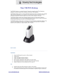
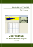
1
USER MANUAL
FOR
BIOSCANNER MICRO AND MACRO
FISH COUNTERS
VAKI AQUACULTURE SYSTEMS
EDITION:
SEPTEMBER 2006
PROGRAM VERSION: 3.38
Vaki Aquaculture Systems – Manual for Bioscanner MICRO and MACRO
CONTENTS
1
PREFACE – THE BIOSCANNER MICRO & MACRO ............................................3
2
WARRANTY....................................................................................................................4
3
ASSEMBLY......................................................................................................................5
4
COUNTING HEAD .........................................................................................................6
5
SET UP..............................................................................................................................7
5.1
5.2
5.3
PUMPING
VACUUM PUMPS
NETTING
7
7
7
6
START UP........................................................................................................................8
7
MAIN SCREEN ...............................................................................................................9
7.1
7.2
7.3
7.4
7.5
8
SET FISH SIZE
TEST WITH WATER ONLY
START COUNTING SESSION
STORE AND CONTINUE COUNTING
END COUNTING SESSION
11
11
11
12
12
SETTINGS......................................................................................................................13
8.1
8.2
8.3
8.4
8.5
8.6
13
13
14
14
14
15
RECORDING WHILE COUNTING
AUTOMATIC SIZE SENSING
FISH TYPE
CONTROL FUNCTION
MULTI CHANNELS
ADVANCED
9
MULTI CHANNEL COUNTING ................................................................................16
10
VIEW REPORT.............................................................................................................17
11
VIEW RECORD ............................................................................................................18
12
CALIBRATION & VISIBILITY .................................................................................19
12.1
12.2
12.3
VISIBILITY
COUNTER CALIBRATION
SETTING EDGE POSITION MANUALLY
13
STORING .......................................................................................................................21
14
TECHNICAL SPECIFICATION.................................................................................22
15
STANDARD COUNTERS ............................................................................................23
-2-
19
20
20
Vaki Aquaculture Systems – Manual for Bioscanner MICRO and MACRO
1 PREFACE – THE BIOSCANNER MICRO &
MACRO
Vaki Aquaculture Systems Ltd thank you for choosing the Bioscanner MICRO and MACRO
range of fry and smolt counters. These counters are used in many aquaculture enterprises
where an accurate knowledge of fish numbers is important. Applications include counting fish
when grading, accurate stock control when transferring fish between tanks and delivering fish
by helicopter, well boat and truck.
The Vaki Bioscanner MICRO and MACRO counters have been developed in collaboration
with a number of leading fish farming companies and are currently being used for counting
Atlantic and Pacific salmon, trout, sea bass, sea bream, cod, and flatfish. Vaki continue to
develop the functions on the counters and for use with additional species including prawn,
shrimp and ornamental fish.
Both counters are based on a digital scanning camera and computer vision. The outlines of
objects that pass beneath the camera are recorded and specially designed software is used to
analyse the images and count the individual fish. The fish enter the counter and the water
from the fish pump or spray bar then carry the fish over the curved counting channel. The fish
pass over a light source and a mirror above reflects the images of each fish into the digital
camera where the outlines are recorded and counted.
The MICRO is ideal when counting small fish from 0.2 g and has a 500mm wide counting
channel, the MACRO channel is 1000mm wide and ideal for counting both fry and larger fish
such as smolts. Both counters can be supplied with multi counting channels, which can be
used to count separate batches of fish simultaneously, for example when grading.
This manual is a guide to the use of the Bioscanner MICRO and MACRO counters.
-3-
Vaki Aquaculture Systems – Manual for Bioscanner MICRO and MACRO
2 WARRANTY
Vaki Aquaculture Systems Ltd. offers warranty for defects that appear within one (1) year
from the date of delivery from Vaki Iceland, on condition that the equipment has been
assembled, used, and maintained in accordance with the instructions for assembly and use.
Changes to the start date of this warranty, such as delayed delivery to the user, must be
reported to Vaki upon receipt of the equipment and agreed in writing.
Vaki undertakes to repair all defects that are due to faults in the design, materials used, or
manufacture of the equipment. These defects will be rectified by repairing the equipment, or
replacing components. The complete unit or parts thereof may be required to return to the
factory in Iceland for repair.
Vaki accepts corresponding warranty for original parts fitted by Vaki as replacements, for a
period of one (1) year from the date supplied.
Vaki will not be liable for:
∗ Incorrect assembly and use, or inadequate maintenance.
∗ Defects which result from the fitting of materials, components, or
∗
∗
∗
∗
∗
∗
∗
∗
devices not supplied by Vaki, and which are purchased and fitted by
the user.
Defects due to changes made to the equipment by the user, without
the written consent of Vaki.
Faulty or inadequate repairs carried out by the user.
Normal wear and tear of the equipment.
Faulty connection of electrical equipment.
Faults caused by excessive voltage.
Damage or stoppage due to immersion of the computer or camera in
water.
Damage to electrical supply cables.
Any economic loss that may arise from production stoppage.
If faults or defects appear in the equipment, the user must report this in writing to Vaki or its
appointed representative as soon as possible, and without unjustifiable delay. The report must
be sent within two (2) weeks from the expiry of the deadline, which is one (1) year from the
date of supply by Vaki Iceland.
If the purchaser does not inform Vaki or its representative within the time limits stated above,
the purchaser shall forfeit the rights of the warranty.
-4-
Vaki Aquaculture Systems – Manual for Bioscanner MICRO and MACRO
3 ASSEMBLY
After delivery, the main parts of the
counter may need to be bolted
together. These are the Counting head,
Counter body, legs, inlet, and outlet.
The legs are assembled and fitted with
the wheels at the front and the inlet and
outlet tubs bolted to the counter body
as shown.
To ensure the camera inside is
correctly positioned it is important that
the counting head is securely fitted
onto the main chassis and firmly seated
on the four corner pads.
Fasten all nuts tightly
The Micro / Macro can be supplied as a single channel unit or with multiple channels or with
different options. The four-channel Macro counter is shown. The main steps in the assembly
are always the same but there may be different inlets and outlets according to customer needs.
Counting
Head
Multi-channel
fish inlet
Counter body
Up-well inlet
Lamp
Housing
De-watering
outlet
Fish outlet
Legs
Other equipment supplied:
2 x USB cables
1 x Standard LAN cable
1 x Bottle Vaki Fluid 1 x External Alarm
1 x Power cable
1xCounter Manual
1 x Computer Manual
Optional equipment includes:
Biomass Function, UPS 80 – 100W (un-interrupted power supply), USBKeyboard, Mouse&
Printer, 2 –way Batch splitter, CD reader/writer, Twisted LAN cable. Internal heating kit.
-5-
Vaki Aquaculture Systems – Manual for Bioscanner MICRO and MACRO
4 COUNTING HEAD
The counting head contains the camera, computer, and touch screen.
On the front are connections and ports required to connect the counter to power supply, lamp,
and for external equipment such as printer, keyboard, external alarm, batch splitter.
Store
1
1.
2.
3.
4.
5.
6.
7.
8.
2
3
4
5
Connection for main earthed power.
On /off power switch.
Local Area Network (LAN) connection.
USB port, for keyboard, printer, mouse.
USB port as above.
Serial Communication Port.
Control port for overload/batch alarm, batch splitter.
Lamp connection.
-6-
6
7
8
Vaki Aquaculture Systems – Manual for Bioscanner MICRO and MACRO
5 SET UP
When setting up the MICRO or MACRO it is important to note the following:
•
•
•
•
•
•
•
•
•
•
The counter should be placed on a flat and stable surface.
Using the level indicator on the frame set the counter level by adjusting the height of
the legs to ensure both fish and water are evenly spread across the scanning area.
Locate the counter so that the touch screen is easily accessible and not exposed to
water or direct sunlight. Note that in hot weather, high temperatures can affect the
computer.
Before each count check that the mirror is completely clean and free from any stains,
residue or water droplets.
Ensure that all pipes and hoses are securely fastened.
Connect the lamp cable to lamp connection on counting head.
Connect external alarm or batch splitter to the “Ctrl” port
Connect the power cable to earthed power outlet. The use of a UPS (un-interrupted
power supply) device is recommend. The counter power requirement is 80-100W.
Ensure that water and fish have a continuous free flow from the counter. Backpressure
in the pipes can overload the counter.
Take care not move or shake the counter while it is operating to protect against hard
disk failure.
5.1 Pumping
When using a fish pump to transfer fish to the counter it is important to ensure an even flow
of fish and water. Uneven delivery of fish to the counter can cause inaccurate counting as the
number of fish may exceed the capacity limits.
It is also important to test the counter on the correct fish size settings pumping water only to
ensure excess water does not create over-counting and adjust pump as required.
Ref: section 7.2 “Test with water only”
5.2 Vacuum pumps
When using larger vacuum pumps it may be necessary to provide additional dewatering or a
buffer tank. Short bursts of many fish can overload the counter and both excess water and
white water can affect the performance of the counter particularly when counting smaller fish.
5.3 Netting
When netting the fish into the counter it is similarly necessary to supply a sufficient amount
of water for gentle handling of the fish and maintain an even flow of fish over the curved
counting channel.
-7-
Vaki Aquaculture Systems – Manual for Bioscanner MICRO and MACRO
6 START UP
The counter is now assembled and set up as instructed.
Turn on counter.
Wait for approximately 10 minutes as the software is
started and lamp heats up. The following window will be
shown on screen.
If the counter has been used recently and the lamp has
not cooled it is possible to skip this by pressing,
“Cancel”.
The main screen will then be shown.
-8-
Vaki Aquaculture Systems – Manual for Bioscanner MICRO and MACRO
7 MAIN SCREEN
The features and options shown on the main screen are as follows.
1
2
3
4
5
6
7
8
Store
1. “New counting session” starts a new counting session, once activated this button will
change to “End counting session”
2. “Store” to store an intermediary batch count to the counting report.
Reminder: remember to store the last batch before ending the counting session
3. “Settings” access settings menus.
4. “Visibility” used to display the graph showing intensity of light detected by camera.
5. “Calibration” to automatically calibrate the counter.
6. “View Record” to view recorded images.
7. “View Report” to view counting reports.
8. “Exit” to close the software before switching of counter.
-9-
Vaki Aquaculture Systems – Manual for Bioscanner MICRO and MACRO
Store
G
H
D
A
A.
B.
C.
D.
E.
F.
G.
H.
B
E
C
F
“Counting” / or “Not counting” message indicates if counter is ready to count.
If this area turns red and shows as “Not counting” and the error message
“visibility insufficient” appears, please refer to Calibration & Visibility Section of
this manual.
Total count including all batches stored in the counting session.
Channel label. The name of the label can be changed in settings.
Buttons to set the size group closest to average fish size to be counted
Size group selected with size group buttons.
Throughput graph, the blue line shows the rate of fish passing through the counter
and the red shows the maximum capacity the counter can accept.
Progress Bar indicates the rate of fish passing through the counter, turning red
when over capacity.
Intermediate batch count.
- 10 -
Vaki Aquaculture Systems – Manual for Bioscanner MICRO and MACRO
7.1 Set Fish Size
The size groups are: 0.2g, 1g, 3g, 10g, 30g, 100g & 200g
Using the size group buttons set the size group closest to the average size you intend to count.
Each size setting covers a range of fish approximately 5 x smaller and 5 x larger than the size
setting.
Should sensitive settings for very small fry count small air bubbles, water disturbance, or
suspended particles it is advisable to increase the initial size range.
7.2 Test with water only
Adjust the amount of water from the fish pump to suit the size of fish being counted. With
smaller fish, reduce the amount of water as much as possible running through the counter to
prevent miscounting. Use the dewatering valve to adjust the water level.
The plastic flap is used to even the flow of water and
fish through the counter.
The dewatering valve is adjusted using this screw
Test run with water only through the counter and check that the counter does not show any
counts due to water disturbance.
It may be necessary to adjust the flow of water to prevent this, particularly with small fry. If
the counter is “counting the water”, this may be due to:
•
•
•
•
•
The surface of the mirror is dirty or has water splashes.
Too much water is being pumped through the counter.
The water may be too dirty.
The counter is not level and/or the water is not evenly spread over the counting
channel.
The size range setting is too sensitive.
7.3 Start Counting Session
To start counting press “New counting session” button on the main screen.
The display will show:
- 11 -
Vaki Aquaculture Systems – Manual for Bioscanner MICRO and MACRO
Text such as the site name, tank identification, the population / year class can be entered by
pressing the keyboard buttons as indicated. This information will be included in the report.
Press “enter” on the keyboard after typing. IT IS IMPORTANT THAT ONLY LETTERS
AND NUMBERS ARE USED WHEN A NAME IS GIVEN. DO NOT USE SIGNS SUCH
AS ( / , . & - OR THE DATA FILE WILL NOT BE SAVED.
The main screen of the program
displays two numbers.
Batch count
0
The counter should now show 0 in
both counting windows. Start
pumping or netting the fish into
the counter.
Total count
0
There are 2 options when you are finished counting a batch of fish.
1. Store current batch and count a new batch to be included in the report for this counting
session.
2. Stop counting and end counting session.
7.4 Store and Continue Counting
The batch count can be stored by pressing the “Store” button. The batch number will be
stored to the report together with the time label. The batch count reset to 0. To continue
counting first reset the size range if required, and start pumping or netting the new batch of
fish.
Example: Start new count and count from tank No 1. 10,000 fish. The Batch count will show
“10000” and the “Total” window the same “10000”. Press “Store” and then from tank, No 2
you count 15,000 fish. The batch count now shows “15000” and the “Total Count” window
shows “25000” fish.
7.5 End counting session
When counting is finished press “End counting session”. The numbers and information
about the counting session are stored into the counting report. It is now possible to view, print
reports and start a new counting session. Note: if counting batches remember to store the last
batch before ending the counting session.
- 12 -
Vaki Aquaculture Systems – Manual for Bioscanner MICRO and MACRO
8 SETTINGS
To access the settings function press “Settings” on the main screen. You will then see the
screen below.
The program version is shown here
8.1 Recording while counting
The counter can record and store images of the counted fish in the memory of the computer.
This function can be used to verify the accuracy of the count.
There are 3 options:
None:
No recording
Sampling:
20 second sequence every 5 minutes.
Continuous: Records all images during the counting session.
NB! The image files are big; 20 seconds of images are approx. 2 MB.
8.2 Automatic Size sensing
Enables the counter to calibrate the counting software to the average size of the fish passing
through the counter. If this option is not checked the counter will not change the size
conditions and will display Disable in the Estimated size window.
It is strongly recommended to keep this option checked.
- 13 -
Vaki Aquaculture Systems – Manual for Bioscanner MICRO and MACRO
8.3 Fish Type
Selects the species for the biomass function.
8.4 Control function
This function is for devices connected to the “Ctrl” connector on the counting head.
There are 4 options:
1. None: No control function activated
2. Overload Alarm: enables an external alarm to
sound when the counter is overloaded.
3. Batch Alarm: sets the external alarm to signal
when the batch number is reached.
4. Batch Splitter: this controls a batch splitter with
twin outlets. This function counts a pre-selected
number of fish through the counter into one
outlet, then automatically switches to the other
outlet and resets the batch count.
Batch Number: This is used to set the number at which
the batch alarm or batch splitter will be activated.
“Reset” this button is used to turn off the external alarm and to switch between outlets on the
batch splitter.
8.5 Multi channels
The Settings screen (below left) is displayed for single channel counting; on the right is the
multi channel counter. The channel positions indicate the width of each counting channel.
The Channel Labels box is used to name the counting channels. To change a multi channel
counter to single channel counting remove the tick from the Multi channel counting box.
- 14 -
Vaki Aquaculture Systems – Manual for Bioscanner MICRO and MACRO
8.6 Advanced
“Line Scan Rate” Shows how many lines per second the camera is scanning.
“Light Strength” This value indicates the strength of the lamp. Normally this value should
be 600 – 900. Should the value drop below 500 this suggests the lamp tube should be
replaced.
Folder for Report and Record files: This shows where the folder is located that stores the
report and image files created after a counting session. The preset folder is c:\reports\.
The file location can be changed by pressing the dotted button to activate the keyboard to type
the folder name and location. The user must be sure that this new folder has been created on
the computer.
Active Biomass function: Indicates the status of the biomass function.
- 15 -
Vaki Aquaculture Systems – Manual for Bioscanner MICRO and MACRO
9 MULTI CHANNEL COUNTING
31.2 gr
The main screen shows the batch numbers for each counting channel and the total at the
bottom.
The names of each counting channel are set up in the settings section. The size groups must
be set for each individual counting channel.
Average weight is indicated with the Biomass function activated.
The average weight is not displayed until the required sample is measured.
The moving blue bar is an indication of the sample level, once sample is complete the blue
bar disappears and the average weight is displayed.
- 16 -
Vaki Aquaculture Systems – Manual for Bioscanner MICRO and MACRO
10 VIEW REPORT
After pressing “End counting session”, the
programme automatically creates a report file. To
open and view the reports press the “View
Report” button on main screen. A list of all stored
counting reports is displayed. Each report is
labelled by date and tank name. The report shows
the total number of fish and the number in all
batches, the total counting time, average counted
fish/min, maximum throughput in fish/min,
overloading time, name of the site and number of
the tank etc. A graph showing the rate of fish
through the counter is included in the report as
shown.
With the Biomass function average weight, , total
biomass, standard deviation, and size distribution
chart is included in the report.
A company logo can be printed on the top left of
the report. The logo must be in a Windows Bitmap
format and under the filename logo.bmp in the
folder c:\ori
- 17 -
Vaki Aquaculture Systems – Manual for Bioscanner MICRO and MACRO
11 VIEW RECORD
To view the images stored press “View Record” on the main screen. The files are labelled by
date and tank name, open the file to be viewed from the list. Each screen shows a recording
for around one-second interval.
The graph at the top of the screen indicates the rate of fish through the counter over time.
◄, ► buttons are used to move to the next screen
|◄ , ►| buttons locate the beginning and end of the recording.
Start/End button, is used to select a part of the recording to be counted.
The pointer indicates the location of the screen currently viewed and can be dragged to
quickly locate a position in the recording.
“Close” to exit.
- 18 -
Vaki Aquaculture Systems – Manual for Bioscanner MICRO and MACRO
12 CALIBRATION & VISIBILITY
Each time the counter starts it calibrates and checks the visibility of the camera. This includes
the following checks:
•
•
The scanning area of the camera.
The intensity of the light detected by the camera.
If the visibility is not acceptable, the following message will appear “Insufficient visibility
check again?” To find what is wrong, push the “Visibility” button.
12.1 Visibility
Press “Visibility” button to show the visibility graph:
The black vertical lines indicate the edges of the area scanned by the camera, which should
correspond to the inside edges of the counting channel.
The “Visibility” function is
also used to check that the
camera
is
correctly
positioned
and
the
amplification of the light is
correct. It is also possible to
check if dirt or residue blocks
or disturbs the sight of the
camera.
This diagram on the left
shows how the graph should
look. It shows the position of
the edges of the scanning
area with two vertical black
lines. It also shows that the light intensity detected by the camera is even. The scanning area
on this graph is the distance between 500 and 1500 on the x-axis, and on the y-axis, the
strength of the light is approx. 220. The x-axis is the length of the scanning area in pixels (1
pixel = 0.5 mm). The graph for Micro should indicate 1,000 pixels (500mm) and the Macro
2,000 pixels (1,000mm). The y-axis is the strength of the light on scale 0 to 255. The counter
ignores the area outside the edges. If the strength is under 180 or over 250, the counter must
be re-calibrated. (See section: 12.2 Counter Calibration)
The diagram on the right shows how the graph can
look when something disturbs the light. In this
case, the reason may be humidity or dirt on the
mirror. This would prevent calibration of the
camera. In this case, it is necessary to clean the
mirror.
- 19 -
Vaki Aquaculture Systems – Manual for Bioscanner MICRO and MACRO
The black vertical lines should be positioned where the light intensity (shown by the red
curve) falls steeply. If not it is necessary to re calibrate (see Counter Calibration).
If no red curve appears this may be caused by, no light source (lamp) or the counting
head is not positioned correctly on the counter body.
12.2 Counter calibration
The Calibration function calculates a new
position automatically. Press “Calibration”
button on main screen with no water running
through the counter.
It is also important that the lamp has been on
for five minutes or more and the mirror and
camera window are clean.
Wait until counting message appears on
bottom left of screen.
It is good practice to re check the “Visibility”
graph. If the edges of the scanning area are still
not acceptable then it may need to be done
manually.
12.3 Setting Edge Position Manually
If, after Calibration, the edge positions are still incorrect then it is possible to set positions
manually. This is done separately for left and right side by pressing the magnifying glass at
each side to zoom in to each edge position. Check the number on the X- axis where the red
line drops. This value should be set as the edge position. Press the “Keyboard button” and set
the number for the edge position.
- 20 -
Vaki Aquaculture Systems – Manual for Bioscanner MICRO and MACRO
13 STORING
When storing the Bioscanner Micro or Macro it is important to bear the following in mind:
•
•
•
Store the Counting Head in a safe, dry place where temperature fluctuations are not
great.
Clean any salty seawater off the counter with fresh water after use.
Ensure the counting head is handled with care.
- 21 -
Vaki Aquaculture Systems – Manual for Bioscanner MICRO and MACRO
14 TECHNICAL SPECIFICATION
Macro Size:
1.6 x 1.2 x 1.6-2.4 m (L x W x H)
Micro Size:
2.4 x 0.7 x 1.6-2.4 m (L x W x H)
Material:
Light source:
Stainless steel (AISI 316L)
Micro Counter
Macro Counter
18W 60cm 18/12-950
36W 120cm 18/12-950
Osram colour ref 950
Power consumption:
UPS requirement:
110/220 V
80-100W
Size of inlet/outlet pipes:
4” or 6”
Size of dewatering pipe:
4” or 6”
Capacity:
Fish size
0,5 g
1g
3g
10 g
30 g
100g
200g
Micro Counter
9500
6500
4300
2800
1600
800
600
Macro Counter
Fry/min
14000
10200
7200
4800
3080
1600
1200
Accuracy:
98% -100%
Fish sizes:
Macro 0.2g – 400g
Micro 0.2g – 200g
Fish species:
Sea bass, sea bream, salmon, trout, halibut, turbot, tilapia, cod, and
ornamentals.
- 22 -
Vaki Aquaculture Systems – Manual for Bioscanner MICRO and MACRO
15 STANDARD COUNTERS
Single Channel Macro
1000 mm
2800 mm
Legs are adjustable for up to 500mm extra height.
Sizes are approx. for a standard counter.
4 Channel Macro Quattro
1600 mm
1300 mm
The Macro counter is split into 4 separate
counting channels. The channel dividers in
the inlet can be removed and the upwelling
inlet used to convert to single channel for fast
deliveries.
- 23 -
Vaki Aquaculture Systems – Manual for Bioscanner MICRO and MACRO
Single Channel Micro
500 mm
2300 mm
The counting channel is 500mm wide x 70mm deep. The Micro can also supplied as a 3
channel counter.
- 24 -