1
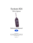
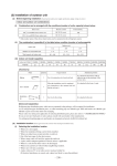
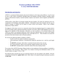
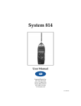
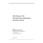
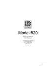
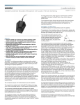
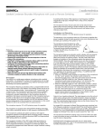
SRC20
Signal Generator
User Manual
Larson¥Davis Inc.
1681 West 820 North
Provo, UT 84601-1341
Phone: (801) 375-0177
FAX: (801) 375-0182
www.lardav.com
P/N: ISRC20.01
SRC20 USER MANUAL
Copyright
Copyright 1998 by Larson¥Davis, Inc. This manual is copyrighted, with all rights reserved.
The manual may not be copied in whole or in part for any use without prior written consent
of Larson¥Davis Inc.
Disclaimer
The following paragraph does not apply in any state or country where such statements are
not agreeable with local law:
Even though Larson¥Davis, Inc. has reviewed its documentation, Larson¥Davis Inc. makes
no warranty or representation, either expressed or implied, with respect to this documentation. This documentation is subject to change without notice, and should not be construed as
a commitment or representation by Larson¥Davis Inc.
This publication may contain inaccuracies or typographical errors. Larson¥Davis Inc. will
periodically update the material for inclusion in new editions. Changes and improvements
to the program described in this manual may be made at any time.
Please examine your instrument and record the following information below. You may be
asked to give this information in any future communications you have with Larson¥Davis,
Inc.
SRC20 Serial # ______________________
ii
Table of Contents
Chapter 1
Introduction
1-1
About This Manual ................................................................................. 1-1
About This Chapter................................................................................. 1-2
Formatting Conventions ........................................................................ 1-2
Features..................................................................................................... 1-3
SRC20 Components ............................................................................ 1-4
System Diagram .................................................................................. 1-6
Getting Started ......................................................................................... 1-6
Unpacking and Inspection................................................................. 1-7
Accessories and Optional Equipment.............................................. 1-7
Connecting Internal or External Power ........................................... 1-8
Automatic Battery Save...................................................................... 1-9
Quick Start ........................................................................................... 1-9
Environmental Considerations ....................................................... 1-10
Chapter 2
Setting Up and Using the SRC20
2-1
Menu Items .......................................................................................... 2-4
Noise Function ............................................................................................2-4
Sine Function...............................................................................................2-5
Memory ................................................................................................ 2-7
Setup Examples ................................................................................... 2-8
EXAMPLE 1.................................................................................................2-8
EXAMPLE 2.................................................................................................2-8
App. A
Technical Specifications
A-1
Pseudo Random Noise Characteristics...........................................A-4
App. B
Serial Port Interface Remote Control
B-1
Interface Cables........................................................................................B-1
Commands ...............................................................................................B-2
i
SRC20 USER MANUAL
ii
CHAPTER
1
Introduction
Welcome to the Larson¥Davis SRC20 Function Generator. Although many users discover the features and
operation of the SRC20 by glancing at its keypad, we
invite you to read this manual to get the most out of
your new Larson¥Davis function generator.
About This Manual
This manual has 2 chapters and 2 appendices covering
the following topics:
¥ Chapter 1 - Introduction: overview of this user
manual and the SRC20Õs features & functions;
unpacking the SRC20; quick start procedures.
¥ Chapter 2- Setting Up and Using the SRC20: overall
system setup; description of each key along with its
function and displays; working with menus.
Appendices
¥ Appendix A - Technical SpeciÞcation: Technical
Discussion and SpeciÞcations: listing of electronic,
environmental, and physical characteristics of the
SRC20.
¥ Appendix B - Serial Port Interface Remote Control:
How to control the SRC20 using remote commands.
Index
6/19/98
Introduction
1-1
About This Chapter
SpeciÞcally, this introductory chapter covers the following topics:
¥ Formatting Conventions: Explanation of the fonts
and other formatting conventions used in this manual.
¥ Model SRC20 Features: A listing of the characteristics of the SRC20 keypad and function.
¥ Getting Started: Instructions for unpacking,
inspecting and initially assembling the SRC20.
Formatting Conventions
This manual uses the following format conventions:
In step-by-step directions, the process (what you do) is
shown in the left column, and the rationale (why you
do it) with other cautions and comments are shown in
the right column.
You may get out of the
menu at any time by hitting the MUTE key or the
SINE key. This is useful
when you have to go into
the menu to modify one of
the settings.
Step 2 Push the NEXT key to access the Les level. Since you
want the return sweep to be attenuated as much as
possible, set this to 40 dB. Now the end-to-start level is
80 dB below the start-to-end level.
Keys to press on the SRC20 are shown in a font representing the appropriate key. For example:
Press the d key.
1-2
SRC20 User Manual
6/19/98
Features
The Larson¥Davis SRC20 has the following features:
General
¥ Two instruments in one: pink and white noise generator and swept sinewave generator
¥ Setting up the generator is accomplished by simple
menus accessed by well labeled keys.
¥ Store and recall up to eight generator setups
¥ The signal is muted at turn on or with any mode
change. The output can be muted at any time by the
touch of a key.
¥ The power source voltage may be checked at any
time.
¥ The SRC20 is powered by an inexpensive, easy to
obtain 9-Volt battery. When powered by the internal 9-Volt battery, the SRC20 turns off when idle
after 10 minutes in the ÒmuteÓ mode. It may also be
powered with an external 8 to 16 Volt power supply.
Noise Generator Features
¥ The pink and white noise generator has a frequency
response of 20 Hz to 20 kHz. It includes a pulse
mode that is adjustable from 1 ms to 25,000 seconds
(<416 minutes)
Sinewave Generator Features
¥ The sinewave generator has a frequency response
of 0.01 to 25 kHz. The Sweep mode can be either
linear or logarithmic with adjustable start to stop
and stop to start times of between 1 ms and 25,000
seconds. The log sweep has an adjustable sweep
rates of between 0.001 to 20 decades/second.
6/19/98
Introduction
1-3
¥ The output level may be adjusted in each mode.
Different levels may be assigned in Òstart to endÓ
and Òend to startÓ while in sweep mode.
Remote Interface
¥ The SRC20 may be connected to and controlled by a
computer with Microsoft Hypertext or other communications program.
¥ Sine waves of up to 126 kHz in 250 Hz increments
may be accessed using the Òhigh sineÓ command.
SRC20 Components
Output Connector
LCD Display
6.5 inches
(16.5 cm)
LARSON•DAVIS
RCL
SRC20
NOISE
SINE
STO
2
3
4
1
NEXT
PREV
MENU
CURSOR
Keypad
OFF
MUTE
MODIFY
ON
BATT
SYNTHESIZED SIGNAL SOURCE
3Ò
(7.6 cm)
Serial Connector
Figure 1-1 SCR20. The SRC20 is a convenient handheld portable signal generator with a simple user
interface.
1-4
SRC20 User Manual
6/19/98
The serial connector is used for external powering and
computer interfacing.
3
4
2
5
1
Figure 1-2 Serial Connector: The serial connector is a 5
pin Switchcraft connector with the following pinout:
1 - Ground
2 - Transmit data negative output (RS-232 levels)
3 - Receive data negative input (RS-422)
4 - External power input (8 - 16 Vdc 40 mA)
5 - Digital I/O
6/19/98
Introduction
1-5
System Diagram
High Sine Filter
D/A
Converter
Anti Alias Filter
Attenuator
0 dB
20 dB
40 dB
60 dB
Output
Select
RS232
Display
DSP
Memory
Power
Supply
Keypad
Figure 1-3 Block diagram of the SRC20.
Getting Started
This section outlines the steps to follow when you Þrst
receive and unpack the SRC 20. The following topics
are covered:
¥ Unpacking and Inspection
¥ Accessories and Optional Equipment
¥ Connecting Internal or External Power
¥ Quick Start
1-6
SRC20 User Manual
6/19/98
¥ Environmental Considerations
Unpacking and Inspection
Your SRC20 has been shipped in protective packaging.
Please verify the package contents with the following
list (Accessories and Optional Equipment) and retain
the shipping containers for safe shipment at a future
date. Report any damage or shortage immediately to
Larson¥Davis, Inc. at (801) 375-0177
Complete and return the Warranty/Registration card.
It will allow us to keep you informed of any version
updates.
If you have not already done so, please record your
instrumentÕs serial number (located on the label on the
back of the SRC20) and the purchase date at the beginning of this manual (see the copyright page). You may
be asked to give this information in any future communications you may have with Larson¥Davis, Inc.
Accessories and Optional Equipment
The SRC20 is delivered with the following standard
accessories:
¥ SRC20 instrument
¥ Alkaline battery, 9-volt
¥ SRC20 User manual
¥ PSA005: AC power adapter (US only) 115 volts AC
to 9 volts DC (Has 5-pin Switchcraft connector to
plug in directly to the SRC20)
¥ CCS009: Cordura nylon pouch
The following optional equipment is also available:
6/19/98
Introduction
1-7
¥ CBL101: Cable to power the SRC20 (Switchcraft 5pin connector) and a 9-pin connector to connect to
RS-232 port of most computers.
¥ CBL063: RS-232 9-pin connector and power cable.
¥ PSA001: 115 Vac to 9 Vdc, 50-60 Hz (used in conjunction with CBL0-63)
¥ CBL038: Connects SRC20 to an external battery and
RS232 port of most computers.
¥ CBL034: Connects SRC20 to un-wired cable end (4conductor shielded).
¥ CBL035: Connects SRC20 to customer supplied
external battery or power supply (with alligator
connectors on one end).
¥ PSA002: AC/DC power adapter, 220 Vac to 9Vdc,
50-60 Hz.
Connecting Internal or External Power
Alternatively, you may use an external power source via pin 1 (GND)
and pin 4 (+) of the 5-pin connector.
To do this, order cable CBL035 from
Larson¥Davis. The SRC20 accepts
8-16 Vdc@40 and is internally fused
at 0.5 A.
WARNING!
To insert the 9-volt battery in the SRC20, slide down
the battery cover on the left hand side of the instrument. Insert the battery with the negative connector
up. Internal battery life is approximately 11 hours.
(Refer to the description in Chapter 2 of this manual
for additional battery information).
Inserting the battery incorrectly can cause damage to
the unit!
If the SRC20 is not being used for long periods of time
(3 months or more), it is recommended that the battery
be removed to avoid possible damage to the instrument.
1-8
SRC20 User Manual
6/19/98
Automatic Battery Save
Certain safeguards have been included.
¥ The SRC20 will turn off when the usable battery
voltage drops below 5.7 volts.
¥ If the SRC20 stays in the mute mode for over 10
minutes while being powered by an internal 9 volt
battery, the SRC20 will automatically turn off to
conserve battery power.
¥ If the SRC20 is being powered by an external power
source that maintains a voltage of greater than 9.5
volts, the unit will not turn off after 10 minutes if in
the muted mode.
¥ The SRC20 will automatically switch between the
internal battery or an external power source - which
ever is greater.
Quick Start
This section will help you turn on the SRC20, check the
battery, access the NOISE and SINE functions, and
turn the instrument off.
Step 1 Turn on the SRC20 by pressing the ON/BATT
key. The Larson¥Davis name appears while
Òbooting up.Ó The serial number and revision number will also appear for a short time.
Step 2 Check the battery level. After the SRC20 is
turned on, you can check the battery level. To
do this, press the ON/BATT key again. Hold
the key down as long as you would like.
Step 3 Press the NOISE and then SINE function keys
and notice how it switches between the two
modes or functions.
Step 4 If the output of the SRC20 is connected to an
ampliÞer and speaker, you can hit the OFF/
MUTE key to generate an output signal.
6/19/98
Introduction
1-9
Step 5 Turn off the instrument. To do this, press and
hold the OFF/MUTE key for about two seconds. The instrument then turns off.
Environmental Considerations
The SCR20 can be used and stored in a wide range of
temperatures, which are free of moisture and condensing humidity conditions. However, common-sense
precautions should be taken. For example, allow the
SRC20 ample time to adjust to abrupt temperature
changes. Condensation may form inside a cold instrument if it is brought into a warm room or vehicle and
may persist long after the outside case has adjusted to
the ambient temperature.
Temperatures inside closed vehicles can also reach
excessive levels. Therefore, do not leave the instrument in
direct sunlight in a vehicle.
1-10
SRC20 User Manual
6/19/98
CHAPTER
2
Setting Up and Using the
SRC20
This chapter contains information on the functions
which are accessed through the SRC20 keypad.
NOISE
SINE
STO
1
2
3
4
PREV
NEXT
RCL
MENU
CURSOR
OFF
MUTE
MODIFY
ON
BATT
SYNTHESIZED SIGNAL SOURCE
Figure 2-1 SRC20 Keypad.
These keys are covered in the order in which they are
typically used.
ON
BATT
6/11/98
ON: Turns on the SRC20
BATT: Push and hold to check the supply voltage.
Setting Up and Using the SRC20
2-1
OFF
MUTE
OFF: Hold down for about 2 seconds
to turn the SRC20 off.
MUTE: Push to activate output or
push to deactivate signal generator
output signal
NOISE
SINE
NOISE (or Noise Function Key): Push
to activate the pink and white noise
options. Pushing the button cycles
through the four available options:
Pink, Pink Pulse, White, & White
Pulse.
SINE (or Sine Function Key): Push to
activate the sine wave generator
functions. Pushing the button toggles
through the four available sine wave
options: Sine wave (single frequency), linear sweep, logarithmic
sweep, and burst.
Note that in the SINE function with
no sweeping or burst, the upper left
hand of the display shows nothing.
STO
RCL
2-2
STO: Store the current setup into one
of eight registers for later recall (4
registers for the NOISE function and
four for the SINE function). This key
would be followed by pushing one of
the 1, 2, 3, or 4 keys.
RCL: Recalls one of eight previously
stored system setups (up to four in
the NOISE function and 4 in the SINE
function). Push either the NOISE or
SINE function key, the RCL key followed by pushing one of the 1, 2, 3,
or 4 keys.
SRC20 User Manual
6/11/98
1
PREV
PREV: used to move up through
menu items.
1: Storage area #1 in which setups
can be stored and recalled.
2
NEXT
NEXT: Used to move down through
menu items.
2: Storage area #2 in which setups
can be stored and recalled
3
Left Arrow: used to move the cursor
through numbers for setting frequencies, levels, and timing functions.
Numbers that can now be modiÞed
blink.
3. Storage area #3 in which setups
can be stored or recalled.
4
Right Arrow: used to move the cursor through numbers for setting frequency, levels, and timing functions.
Numbers that can now be modiÞed
blink.
4: Storage area #4 in which setups
can be stored and recalled
Up Arrow: used to increase the value
of numbers currently blinking.
Down Arrow: used to decrease the
value of numbers currently blinking.
6/11/98
Setting Up and Using the SRC20
2-3
Menu Items
Noise Function
To access various NOISE modes, cycle though the various options by pushing the NOISE key. Depending on
where you start, pushing the NOISE key cycles as follows: PINK, PINK PULSE, WHITE, & WHITE PULSE
and then PINK again as displayed on the screen.
You may use the PREV key to get
out of the menu area or you may
push the MUTE or NOISE function
key at any time to quickly exit from
the menu area.
To access the menu items associated with the NOISE
function, use the PREV or NEXT key. It will allow you
to move through the various menu items. Below is a
chart that shows the available menu settings.
Options Using
Noise Function Key:
Menu Setting Options
(Accessed by using the
NEXT and PREV key):
Description:
PINK
Level
Adjust output level between 40 to 120
dB by use of the modify keys. The cursor can be moved by use of the right or
left cursor keys.
PINK - PULSE
Level
Adjust output level.
Ton
The NEXT arrow will take you to the
Ton menu item. Adjust the time the
pink noise is on.
Toff
Push the NEXT key again to set the
time the pink noise is off.
Level
Adjust the output level (between 40
and 120 dB) by the use of the Modify
keys. The cursor may be moved by use
of the Cursor keys.
WHITE
2-4
SRC20 User Manual
6/11/98
WHITE - PULSE
Level
Adjust the output level. Push the
NEXT key to go to the Ton menu item.
Ton
Adjust the time the White noise is on.
Toff
Push the NEXT key again to set the
time the white noise is off.
Sine Function
Note that in the SINE function with
no sweeping or burst, the upper left
hand of the display shows nothing.
To access various SINE functions, toggle through the
various options by pushing the SINE key. Depending
on where you start, pushing the SINE key toggles as
follows: SINE, LIN (linear sweep), LOG (logarithmic
sweep), and BRST (burst) and then SINE again as displayed on the screen.
You may use the PREV key to get
out of the menu area or you may
push MUTE or NOISE function key
at any time to quickly exit from the
menu area
To access the menu items associated with the SINE
function, use the PREV or NEXT key. It will allow you
to move through the various menu items. Illustrated
below is a chart showing the available menu settings.
Note that the generator will immediately become unmuted as soon as the
MUTE switch is pushed.
Options using
the Sine Function key:
Menu Setting Options
(Accessed by using the
NEXT and PREV key):
SINE
Frequency
Adjust frequency by use of the MODIFY and CURSOR keys.
Level
The NEXT key will take you to the
level adjustment. Adjust the output
level by use of the MODIFY and CURSOR keys.
6/11/98
Description:
Setting Up and Using the SRC20
2-5
SINE LINEAR
SWEEP
SINE LOG
SWEEP
2-6
Start Frequency
Adjust the start frequency by use of
the CURSOR and MODIFY
keys.
Lse
Adjust the output level for the start to
end of the sweep. The level immediately moves to this new level at the
start of the sweep.
End Frequency
Adjust the end frequency by use of the
MODIFY and CURSOR keys.
Les
Adjust the output level for the end to
the start of the sweep.
Tse
Adjust the time (in sec.) it takes to
move from start of the sweep to the
end of the sweep.
Tes
Adjust the time (in sec.) it takes to
move from the end to the start of the
sweep.
Start frequency
Push the NEXT key to access the start
frequency. Adjust the start frequency
of the log sweep by use of the CURSOR and MODIFY keys.
Lse
Adjust the output level of the start to
end level of the sweep. The level
immediately goes to this new level at
the start of this sweep.
End Frequency
Adjust the end frequency by use of the
MODIFY and CURSOR keys.
Les
Adjust the output level of the end to
the start of the sweep.
Rse
Adjust the rate (in decades/second) of
the log sweep from the start to the end.
Res
Adjust the rate (in decades/second) of
the log sweep from the end to the start.
SRC20 User Manual
6/11/98
BURST
Start Frequency
Adjust the start frequency of the burst
by use of the CURSOR and MODIFY
keys.
Lse
Adjust the output level of the start to
the end level of the burst.
End Frequency
Adjust the end frequency by use of the
MODIFY and CURSOR keys.
Les
Adjust the output level of the end to
the start-level of the burst.
Nse
Adjust the number of cycles it takes to
get from beginning of the burst to the
end of the burst (1 to 999, 000,000).
Nes
Adjust the number of cycles it takes to
get from the end of burst to the start of
burst (1 to 999,000,000)
Memory
Nonvolatile memory means that you
are not dependent on the SRC20 battery to maintain the memory.
The setups may be stored in one of eight nonvolatile
memories - four for the NOISE function and four for
the SINE function. Storing is simply done by pushing
either the NOISE or SINE key, the STO key and then
one of the 1, 2, 3, or 4 memory keys. This will store the
current settings in the memory location you have chosen.
Setups that arenÕt stored are lost
when the SRC20 is turned off.
You must be in either the main
NOISE or SINE window and not in
one of the menus windows to perform a setup store or recall.
6/11/98
To recall a previously stored setup, push the NOISE or
SINE key, RCL key, and then the relevant memory
number key.
Setting Up and Using the SRC20
2-7
Setup Examples
EXAMPLE 1
You want to perform equalization of a sound system in
a stadium. You connect the SRC20 to either a microphone or line-level input of the sound system. The
sound system level should be turned down until the
SRC20 is on and set.
Step 1 Turn the SRC20 on by pushing the ON key.
Wait for the unit to Òboot up.Ó
Step 2 Check the battery voltage by holding down
the ON/BATT key to make certain the battery
will last through the session (it would be
good to have an additional battery or AC
power available).
Step 3 Push the NOISE key to access PINK noise. If
it doesnÕt immediately appear on the screen,
continue to push the NOISE key until PINK
appears on the screen.
Step 4 Adjust the output level by using the CURSOR
keys and MODIFY keys. If you are using a
microphone input to access the sound system,
adjust the level to around 80 dB.
Step 5 Now push the MUTE key to activate the output.
Step 6 Turn the sound system up to the appropriate
level to perform the test. The SRC20Õs output
level may also be adjusted if its output level is
too low or too high.
Step 7 Push the MUTE key when the test is complete
or to get ready for an additional test.
Step 8
Push and hold the OFF key to turn the SRC20
off.
EXAMPLE 2
You need to perform a test in a laboratory and need a
linear swept sine wave in your test. The frequency
sweep needs to go from 20 Hz to 20,000 Hz and take
one minute to go from the start to the end of the sweep.
2-8
SRC20 User Manual
6/11/98
You want the end to start sweep attenuated as much as
possible and donÕt want it to start the next sweep until
3 minutes after the previous.
Step 1 You can choose to operate the SRC20 using
the internal battery or you may choose to
plug the external power supply into it.
Step 2 Turn the SRC20 on by pushing the ON key.
Wait for it to Òboot up.Ó
Step 3 You may want to check the battery voltage to
make certain your external power supply is
working satisfactorily. Push and hold the
ON/BATT key.
Step 4 Continue to push the SINE key until the LIN
screen appears.
Step 5 Push the NEXT key and set the Start Frequency to 20 Hz with the Cursor and Modify
keys.
Step 6 Push the NEXT key and set the level to 120 dB
by use of the CURSOR and MODIFY keys.
Step 7 Push the NEXT key again and set the END
frequency to 20,000 by use of the CURSOR
and MODIFY keys.
You may get out of the menu at any
time by hitting the MUTE key. or
the SINE key. This is useful when
you have to go into the menu to modify one of the settings.
Step 8 Push the NEXT key to access the Les level.
Since you want the return sweep to be attenuated as much as possible, set this to 40 dB.
Now the end-to-start level is 80 dB below the
start-to-end level.
Step 9 Push the NEXT key to set the time it takes to
go from the start of the sweep to the end of
the sweep. Set this to 60 seconds.
Step 10 Push the NEXT key to set the time it takes to
go from the end of the sweep to the start. Set
this to 180 seconds (3 minutes).
6/11/98
Setting Up and Using the SRC20
2-9
Step 11 Push the NEXT key to go to the LINEAR
SWEEP window so that you can watch what
is going on with the sweep.
On the screen you will see the Ò>>Ó
and Ò<<." They show:
Step 12 Push the MUTE key to turn on the SRC20
output.
Ò>>Ó: sweeping start to end
Step 13 Push MUTE when the test is completed.
Since you would like to use your setup at
another time, you store the setup in memory
2 by pushing the STO key and then the 2 key.
Ò<< Ò: sweeping end to start
Step 14 Turn the SRC20 off by holding down the OFF
key for about two seconds.
2-10
SRC20 User Manual
6/11/98
APPENDIX
A
Technical SpeciÞcations
SpeciÞcations are subject to change without notice.
Numerical values given are typical. Refer to speciÞc
calibration or test results for accurate data on a speciÞc
unit.
Frequency
Characteristics
Sine Wave:
Pink Noise:
White Noise:
High Sine:
Sine Wave
Spectral Purity
Harmonic Distortion
1 Hz to 10 kHz:
10 kHz to 20kHz:
6/11/98
0.01 Hz to 25 kHz
20 Hz to 20 kHz
1 Hz. to 20 kHz
250 Hz to 126 kHz
80 dBc
65 dBc
A-1
Output
Characteristics
Sine Wave Amplitude
(into ≥10 k ohm):
Sine Wave Accuracy
(at 1 kHz):
Sine Wave Flatness
(relative to 1 kHz):
High Sine Flatness
(relative to 1 Khz. Only
available using computer
command):
± 0.02 dB (max)
< 10 kHz: ±0.1 dB (max)
10 kHz to 16 kHz: ±0.2 dB (max)
10 kHz to 20 kHz: ±0.2 dB (max)
16 kHz to 20 kHz: ±0.4 dB (max)
20 kHz to 25 kHz: ±0.8 dB (max)
250 Hz to 10 kHz, -0.00 dB ±0.1 dB
12.5 kHz, -0.02 dB ±0.1 dB
15.75 kHz, -0.04 dB ±0.1 dB
20.0 kHz, -0.06 dB ±0.1 dB
25.0 kHz, -0.10 dB ±0.2 dB
31.5 kHz, -0.16 dB ±0.3 dB
40.0 kHz, -0.26 dB ±0.4 dB
50.0 kHz, -0.41 dB ±0.6 dB
63.0 kHz, -0.65 dB ±0.8 dB
79.4 kHz, -1.02 dB ±1.0 dB
100.0 kHz, -1.55 dB ±1.5 dB
126.0 kHz, -2.30 dB ±2.0 dB
High Sine Frequency
Resolution:
250 Hz
High Sine Amplitude
Accuracy at 1 kHz:
±0.1dB
High Sine Amplitude
Resolution:
0.01 dB
Pink Noise Output Level
(set at 120 dB):
White Noise Output Level
(set at 120 dB):
Output Impedance:
Connector:
A-2
40 to 120 dBµV (100 µV to 1 Vrms)
0.04 to 0.058 Vrms
0.0476 Volts (-26.4 dBV) Typical
0.25 to .28 Volts
0.27 Volts (-11.3 dBV) Typical
50 ohms
BNC Female
SRC20 User Manual
6/11/98
Frequency
Sweep
Type
Direction
Start/Stop Frequency
(direction changes at zero
crossing)
Times
Rates
linear or logarithmic
up or down
0.01 Hz to 25 kHz
1 ms to 25,000 seconds
0.001 to 20 decades/second
Sine Burst
Cycles
1 to 999 million
Pulsed Noise
Times
1 ms to 25,000 seconds
Mute
At turn on or mode change, the signal
is muted. Signal is manually unmuted.
Battery
Reads internal battery voltage or externally applied voltage to tenths of a
volt. SRC20 turns off below 5.7 volts.
Battery Save
Power Supply
SRC20 automatically turns off if voltage is below 9.5 volts and unit has
been muted for 10 minutes.
Internal
External
Power Consumption
General
Operating Environment
Dimensions (W x H x D)
Weight
Remote
Interface
(RS232)
5 Pin Switchcraft TB5M
(male)
6/11/98
9 volt Battery
NEDA 1604A IEC 6LR6
6 to 16 Vdc
(SRC20 uses internal or external which
ever is higher)
37 mA @ 9V, 340 mW
0 to 50°C, 95% RH non condensing
3 x 1 x 6.5 in. (7.62 x 2.54 x 16.5 cm)
7.9 oz. (246 grams)
Pin 1: ground
Pin 2: TXD output
Pin 3: RXD input
Pin 4: External power input
Pin 5: Digital I/O
A -3
Pseudo Random Noise Characteristics
Modern noise generators are principally designed by
digital synthesis. This means that signals are not
totally random. However, signals that do not repeat for
a substantial time are functionally equivalent if the
repeat period is much longer than any system response
to be tested. The advantages of digital generation are
repeatability and stability. The noise generator in the
SRC20 is a 24 bit shift register with feed back. This creates a maximum length sequence of 224-1 samples long.
The sample rate is 102.4 kHz. The sequence repeats
about every 3 minutes. The frequency shaping is controlled by digital Þlters. This makes the output spectrum very stable and accurate.
A-4
SRC20 User Manual
6/11/98
APPENDIX
B
Serial Port Interface Remote
Control
The SRC20 is fully controllable remotely via the Serial
Port interface. Settings and operational mode can be
altered.
This appendix will describe the Serial Port interfacing
of the SRC20 and the various interface commands with
their syntax. Microsoft Hypertext or similar communication programs may be used to send commands out
to the SRC20.
Interface Cables
Serial Port communications are made through the 5pin connector at the base of the SRC20. The instrumentÕs signals conform to the RS232 standard using
either the optional CBL101 (or the CBL063). If additional length is needed, a readily available computer
serial cable may be used or you may use a Larson
Davis CBL077.
Baud rate, Serial Port address and
handshaking protocol are selected
using the computer communication
software. The SRC20 uses a 9600
baud rate, 1 stop bit, and no parity.
Step 1 With the instrument turned off, insert the
cable connector in the 5-pin port.
Step 2 Connect the cable to the of the computer.
Step 3 Open the communications software and connect.
6/18/98
B-1
RS-232 Port -Pin conÞguration for the SRC20 is as follows:.
Switchcraft¨ 5-Pin Male
Connector on SRC20
Pin 1 Ground
Pin 2 TXD Output
Pin 3 RXD Input
Pin 4 Ext. Power Supply
Pin 5 Digital I/O
Computer 9-pin RS-232C
Connector End
GND Pin 5 Ground
RD
Pin 2 Receive Data
TX
Pin 3 Send Data
No Connection
Commands
The commands are a series of ASCII characters with an
alpha command and one or two numeric operands followed by a carriage return line feed.
Note: HIGH SINE MODE is only
available by the use of commands. It
extends the sine wave frequency
response to 126,000 Hz in 250 Hz
increments.
COMMAND
The following tables summarize all of the commands
and are listed in this order: GENERAL, SINE MODE,
NOISE MODE, HIGH SINE, and SPECIAL.
RESPONSE
EXAMPLE
GENERAL
M¯
Set to sine mode
M1
Set to noise mode
M59
Set to high sine mode
QM or ?M
Responds with number
above.
If you were to send the Ò?MÓ command, you would get Ò1 cr lfÓ if you
were in the noise mode.
SINE MODE
B-2
SRC20 User Manual
6/18/98
F start, end
Set frequencies. The end
value is optional if no
sweep.
ÒF1000.09, 21235.78 cr lfÓ will set start
to 1000.09 Hz and end to 21235.78 Hz.
Does not change mute status
QF or ?F
Will return set frequencies
Lse, es
Set levels for start to end
and end to start sweeps. Lse
is used for non sweep
modes.
L100, 40.00
It will unmute the source.
QL or ?L
Will respond with above
settings.
S type, se,es
Set the sweep type for sines,
and timing parameters.
If type is 0, No sweep
If type is 1, Linear sweep, se
is time start to end and es is
time end to start.
If type is 2, Log sweep, se is
rate start to end and es is
rate end to start.
If type is 3, Burst sweep, se
is cycles start to end, es is
cycles end to start.
ÒS0 cr lfÓ no sweep
ÒS1, 1.23, .001Ó linear sweep 1.23 seconds start to end. 0.001 seconds end to
start.
Mutes the source.
QS or ?S
6/18/98
Will respond as above
B -3
NOISE MODE
N type, ton, toff
Type is 0 for pink
Type is 1 for white
Type is 2 for pulsed pink
Type is 3 for pulsed white
If pulsed, ton is duration of
high level and toff is duration off.
N command will mute the
source.
QN or ?N
Responds as above
L level
Sets noise level as above
and unmutes the source
QL or ?L
Responds as above
HIGH SINE MODE
Warning: the only commands that may be used in
this mode are the following
two. Sending other commands while in the this
mode will generate spurious noise superimposed on
the sine wave.
H frequency,
level
In this case frequency is an
integer that is in units of 250
Hz, i.e. 100 = 25,000 Hz.
Level is also an integer
range 0 to 32767. The value
is scaled so that 32767 is 1
volt.
QH or ?H
Responds as above
SPECIAL
COMMANDS
@
Will reboot the SRC20
QV or ?V
Will read the battery voltage. It will return hex value
in .1 volt units.
B-4
SRC20 User Manual
6/18/98
Index
SINE 2-2
STO 2-2
storage area 1 2-3
storage area 2 2-3
storage area 3 2-3
storage area 4 2-3
Numerics
1 key 2-3
2 key 2-3
3 key 2-3
4 key 2-3
B
BATT
key 2-1
BURST
Sine function 2-7
C
Connector
Serial Connector 1-5
Conventions
Formatting 1-2
D
Down Arrow
key 2-3
F
Format
Conventions 1-2
Formatting Conventions 1-2
K
Keypad 2-1
Keys
BATT 2-1
down arrow 2-3
left arrow 2-3
MUTE 2-2
NOISE 2-2
ON 2-1 to 2-2
PREV 2-3
RCL 2-2
right arrow 2-3
6/11/98
L
Left Arrow
key 2-3
M
Memory
storing setups 2-7
MUTE
key 2-2
N
NOISE
key 2-2
Noise Function 2-4
Pink 2-4
pink pulse 2-4
white 2-4
white pulse 2-5
O
OFF
key 2-2
ON
key 2-1
P
Pin B-2
Pin configurations B-2
PREV
key 2-3
Index-1
Q
U
Quick Start 1-9
Unpacking and Inspection 1-7
Up Arrow
key
Keys
up arrow 2-3
R
RCL
key 2-2
Right Arrow
key 2-3
RS-232 interface B-1
W
White Pulse
noise function 2-5
S
Serial number 1-7
Setups
examples 2-8
storage area 1 2-3
storage area 2 2-3
storage area 3 2-3
storage area 4 2-3
storing 2-7
SINE
key 2-2
sine function 2-5
Sine function
burst 2-7
sine 2-5
sine linear sweep 2-6
sine log sweep 2-6
SINE LINEAR SWEEP
sine function 2-6
SINE LOG SWEEP
Sine function 2-6
SRC20
Accessories and Optional Equipment 17
Components 1-4
Features 1-3
General Features 1-3
optional equipment 1-7
System Diagram 1-6
STO
key 2-2
Index-2
SRC20 User Manual
6/11/98