1
(3) Installation of outdoor unit
(a) Before beginning installation (Check that the models, power supply specifications, piping, wiring are correct.)
Indoor and outdoor unit combinations
(i)
Combination can be arranged with the conditions (number of units, capacity) shown below.
Indoor unit
FD
FD
Remote control
KXE6 Series indoor unit
A
Connectability
RC-E3 (2 cores)
OK
RC-E1 (3 cores)
KXE4 Series indoor unit
* Only indoor units of the above-listed series can be connected in the refrigerant system.
(ii) The combination is possible if in the table below condition (number of units,capacity).
Indoor unit
112
1~6
90 ~ 168
Number of connectable units
Total capacity of indoor units
Outdoor unit
140
1~8
112 ~ 210
155
1~8
124 ~ 232
90KXE6 112KXE6 140KXE6 160KXE6
(iii) Indoor unit model capacities
Indoor unit Model
22KXE6
28KXE6
36KXE6
45KXE6
56KXE6
71KXE6
Capacity
22
28
36
45
56
71
90
112
140
160
[Accessory]
Name
Quantity
Usage location
Attachment position
It is attached to the bracket with an
adhesive tape in the proximity of the
service valve.
1
Use it for protection of a knock-out hole.
It is attached to the front of a unit.
UserÕs manual
1
When the installation work is completed,
give instructions to the customer and ask
him/her to keep it.
Installation
kit
1
Use it to fix the wiring.
It is attached in the unit.
Edging
[Items sold separately]
Refrigerant pipe distribution parts, which are not contained in the package, will be required for installation.
As for refrigerant pipe distribution parts, we offer branching pipe sets (Model type: DIS) and header sets (Model type:
HEAD) as parts used on the indoor side of piping.
Please select one suiting your application. In selecting distribution parts, please also refer to “4. REFRIGERANT PIPING.”
If you are not sure which parts to select, please consult with your dealer or the manufacturer.
Use refrigerant branching pipe sets and header sets designed exclusively for R410A without fail.
(b) Installation location (Obtain approval from the customer when selecting the installation area.)
(i)
Selecting the installation location
Where air is not trapped.
Where the installation fittings can be firmly installed.
Where any object does not prevent inlet or outlet air.
Out of the heat range of other heat sources.
Where strong winds will not blow against the outlet air.
A place where stringent regulation of electric noises is applicable.
Where it is safe for the drain water to be discharged.
Where noise and hot air will not bother neighboring residents.
Where snow will not accumulate.
A place where no TV set or radio receiver is placed within 5m.
(If electrical interference is caused, seek a place less likely to cause the problem)
-
238 -
Please note
CAUTION
a) If there is a possibility of a short-circuit, then prepare an additional adapter
Please leave sufficient clearance
to prevent a short-circuit.
around the unit without fail.
b) When installing multiple units, provide sufficient intake space so that a
Otherwise, a risk of compressor
short-circuit does not occur.
and/or electric component failure
c) In areas where there is snowfall, install the unit in a frame or under a
may arise.
snow hood to prevent snow from accumulating on it.
(Inhibition of collective drain discharge in a snowy country)
d) Do not install the equipment in areas where there is a danger for potential explosive atmosphere.
e) Install the equipment in a location that can sufficiently support the weight of the equipment.
f) If a unit is installed into a special environment as shown below, there will be a danger that the corrosion of the outdoor
unit or its malfunctioning is caused. If this is the case, please consult with the distributor from whom you have purchased
the unit.
• Where corrosive gas is generated (such as a hot-spring resort area).
• Where the unit is subject to sea breezes (coastal area).
• Where the unit is subject to oil mists.
• Where equipment generating electromagnetic waves exists in the vicinity.
g) When strong winds occur
● Where it is likely that the unit is subjected to strong winds, provide wind guards according to the following guidelines.
Strong winds can cause performance degradation, an accidental stop due to a rise of high pressure and a broken fan.
q Place the unit outlet pipe perpendicular to the wind direction.
w Please install so the direction of
the air from the blowing outlet
will be perpendicular to the direction of the wind.
e When the foundation is not level,
use wires to tie down the unit.
Wind direction
Over 500 mm
Wind direction
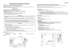
(ii) Installation space (Ex. servicing space)
a) Minimum installation space (Please select an installation point with due attention to
the direction of installation of the refrigerant pipe)
(If the installation conditions shown in this drawing are not satisfied, please consult
with your dealer or the manufacturer.)
b) When units are installed side by side, leave a 10 mm or wider service space between
the units.
c) Walls surrounding the unit in the four sides are not acceptable.
d) There must be a 1-meter or larger space in the above.
e) A barrier wall placed in front of the exhaust diffuser must not be higher than the unit.
Fasten with anchor bolts
Air
inlet
L2
L3
L4
Air
inlet
Air
outlet
Service
space
L1
(Unit : mm)
Size
Sample
I
II
III
L1
Open
Open
500
L2
300
5
Open
L3
150
300
150
L4
5
5
5
(c) Unit delivery and installation (Take particular care in carrying in or moving the unit, and always perform such an operation with two or more persons.)
CAUTION
When you sling the unit for portage, do not fail to take into consideration the deviation of the gravity center from its center.
Improper slinging may cause the unit to lose balance and fall.
Patch plate
Delivery
● Deliver the unit as close as possible to the installation site before removing it from the
packaging.
● If unpacked and deliver cannot be avoided, use a nylon sling or a rope with pads
placed where the rope contacts the unit so it is not scratched.
Wooden pallet
Heavy
Portage
● The right hand side of the unit as viewed from the front (diffuser side) is heavier. A
person carrying the right hand side must take heed of this fact. A person carrying the
left hand side must hold with his right hand the handle provided on the front panel of
the unit and with his left hand the corner column section.
-
239 -
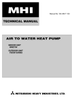
20
Bolt fastening positions
190
Air outlet
580
200
20
410
Air inlet
Anchor bolt position
(4 locations)
● In installing the unit, fix the unit's legs with bolts specified below.
Fasten with bolts
(M10-12)
Use a long block to extend the width.
●
●
●
●
Use a thicker
block to anchor
deeper.
The protrusion of an anchor bolt on the front side must be kept within 15 mm.
Securely install the unit so that it does not fall over during earthquakes or strong winds, etc.
Refer to the above illustrations for information regarding concrete foundations.
Install the unit in a level area. (With a gradient of 5 mm or less.)
Improper installation can result in a compressor failure, broken piping within the unit and abnormal noise generation.
Important
In case that the unit operates in cooling mode, when the outdoor temperature is –5°C or lower, please equip a flex flow adapter
and a snow guard hood (option) on the unit.
(4) Refrigerant piping
(i)
Determination of piping specifications (Please select from the following matrix according to indoor unit specifications and installation site conditions)
Refrigerant piping restrictions
Please do not fail to observe the following pipe sizes and limitations of use.
A failure to observe this instruction can result in a compressor failure or performance degradation.
●
●
●
●
●
●
Please avoid forming any trap (
) or bump (
) in piping as they can cause fluid stagnation.
Maximum length (To the farthest indoor unit) .......................................... Within 70m
Equivalent length (To the farthest indoor unit) ......................................... Within 95m
Total pipe length (Combined total length of pipes) ................................ Within 100m
ø9.52 pipe length ....................................................................................... Within 50m
Height difference
(1) When the outdoor unit is above the indoor unit ................................. Within 30m
(2) When the outdoor unit is below the indoor unit ................................. Within 15m
(3) Height difference between indoor units in the same system .............. Within 15m
(4) Height difference between indoor units and first branch ................... Within 15m
Refrigerant piping size selection
● Please use pipes clean on both the inside and outside and free from contaminants harmful to operation such as sulfur,
oxides, dust, chips, oil, fat and water.
● Use the following material for refrigerant piping.
Material: phosphorus deoxidized seamless copper pipe (C1120T-0, JIS H3300)
● Thickness and size: Please select proper pipes according to the pipe size selection guideline.
(Since this unit uses R410A, Select pipes having a wall thickness larger than the specified minimum pipe thickness.
● For branching pipes, use a genuine branching pipe set or header set at all times.
● Install a branching pipe set, paying attention to the direction of attachment, after you have perused through the installation
manual supplied with it.
● The length of piping from outdoor unit to first branch is 1.5m or more.
● For the handling of service valves, please refer to 4-2. Piping work.
-
240 -
q Individual flow division method
● For determination of appropriate branching joint or different diameter pipe joint sizes, please refer to "Branching Pipe
Set," (which can be purchased separately).
Attention
● Please use pipes of the pipe size specified for the outdoor unit for the section between the outdoor unit and the first
branching joint.
● An appropriate pipe size between branching joints can vary depending on the connected indoor unit capacity
(total capacity connected downstream), please select an appropriate pipe size from the table shown on the right.
● The pipe size between the branch pipe and the indoor unit should
Item
Liquid pipe
Gas pipe
Model
match that of the indoor unit.
Outdoor unit
¿9.52
¿15.88
All model
Main pipe
● Always install branch pipes either horizontally or vertically.
Total capacity of
indoor units
less than 70
70 or more
¿12.7
¿9.52
¿15.88
¿9.52
Vertical
Horizontal
Floor surface
Floor surface
Floor surface
Floor surface
w Header Method
● Depending on the number of units connected, connect blind pipes to header branching points (on the indoor unit
connection side).
● For determination of appropriate header, different diameter pipe joint and blind pipe sizes, please refer to "Header
Set," (which can be purchased separately).
Attention
● For the section between an indoor unit and the header, use a pipe of the diameter specified for the indoor unit.
● To couple with the header, use a different diameter pipe joint to adjust to the pipe diameter specified for the indoor unit.
● The header must be so installed that it branches horizontally (for both gas and liquid)
Horizontal
Gas side
Floor surface
Floor surface
Floor surface
Horizontal
Liquid side
Horizontal
Floor surface
Floor surface
Floor surface
Unit piping specifications
The piping material should be phosphorus deoxidized copper seamless steel pipes. (C1220T, JIS H3300)
Gas side
Pipe diameter Minimum pipe wall
(mm)
thickness (mm)
Outdoor unit 112, 140, 155
¿15.88
1.0
¿ 9.52
0.8
22
¿ 9.52
0.8
28
¿12.7
0.8
36
¿12.7
0.8
45
¿12.7
0.8
56
Indoor unit
¿15.88
1.0
71
¿15.88
1.0
90
¿15.88
1.0
112
¿15.88
1.0
140
¿15.88
1.0
160
Item
Model
Connection
method
Flare
Attention
● Always select pipes meeting the minimum wall thickness requirement.
-
241 -
Liquid side
Pipe diameter Minimum pipe wall Connection
(mm)
method
thickness (mm)
¿9.52
0.8
¿6.35
0.8
¿6.35
0.8
¿6.35
0.8
¿6.35
0.8
¿6.35
0.8
Flare
¿9.52
0.8
¿9.52
0.8
¿9.52
0.8
¿9.52
0.8
¿9.52
0.8
e Selection of on indoor unit side branching pipe set
Method of selecting a branching pipe set
• As an appropriate branching pipe size varies with the connected capacity (total capacity connected downstream),
determine a size from the following table.
a) KX series
Notes(1) In connecting an indoor unit with the indoor unit side branching
pipe set, plase use a pipe conforming to the pipe size specified for
indoor unit connection.
(2) Always install branching joints (for suction gas, discharge gas and
liquid) in such a manner that that they form either correct horizontal or vertical branch.
Branching pipe set
DIS-22-1
DIS-180-1
Total capacity downstream
Less than 180
180 or more but less than 371
Unit: mm
Reducer
• Branch pipe set shapes
Liquid line
94
370
448
ID
¿12.7
¿9.52
91 ¿6.35
ID
¿9.52
¿12.7
¿15.88
Liquid line
ID25.4
OD22.22
100
ID22.22
OD19.05
544
100
ID
¿19.05
¿15.88
¿12.7
117 ¿9.52
ID
¿15.88
¿19.05
¿22.22
DIS-180-1
Gas line
ID28.58
OD22.22
442
ID
¿9.52
87 ¿6.35
Branch pipe
Item
Reducer
ID
¿15.88
¿12.7
¿9.52
ID
¿12.7
¿15.88
¿19.05
DIS-22-1
Gas line
Model Item
ID
¿9.52
Branch pipe
100
Notes(1) Insulation is provided with the branch pipes.
(2) Pipes should be cut to the installation site requirements, with the pipe being severed at the center part of the desired diameter.
(3) Branch joints (gas & liquid) must be installed as either a "horizontal branch" or a "vertical branch".
r Header Method
• Depending on the number of units connected, connect plugged pipes (to be procured on the installer’s part) at a
branching point (on the indoor unit connection side).
• For determination of appropriate header, different diameter pipe joint and blind pipe sizes, please refer to “Header
Set,” (which can be purchased separately).
Total capacity downstream
Less than 180
180 or more but less than 371
Header set model type
HEAD4-22-1
HEAD6-180-1
Number of branches
4 branches at the most
6 branches at the most
Unit: mm
• Header pipe set shapes
OD22.22
ID25.4
ID
¿15.88
¿12.7
¿9.52
104
ID
¿12.7
¿9.52
35
375
ID
¿15.88
¿12.7
¿9.52
Liquid line
ID
¿22.22
¿19.05
¿15.88
545
100
Header pipe
ID
¿6.35
Liquid line
ID
¿12.7
¿9.52
OD22.22
ID28.58
145
415
Item
135
ID
¿12.7
¿9.52
¿6.35 107
Reducer
ID
¿19.05
¿15.88
¿12.7
Header pipe
190
HEAD6-180-1
Gas line
HEAD4-22-1
Gas line
Model Item
540
100
Notes(1)
(2)
(3)
(4)
Insulation is provided with the branch pipes.
Pipes should be cut to the installation site requirements, with the pipe being severed at the center part of the desired diameter.
Branch joints (gas & liquid) must be installed as either a "horizontal branch" or a "vertical branch".
Indoor units 224 and 280 can not connected to the header.
-
242 -
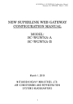
Example of piping
■ Branch system
Outdoor unit: FDC155KXES6
Indoor unit: Combination of 8 units
[Branch pipe set : DIS-22-1 ´ 7 set]
[Total capacity: 176]
¥ Selecting piping size
FDCA155
Outdoor unit
Branch Branch Branch Branch Branch Branch
piping 1 piping 2 piping 3 piping 4 piping 5 piping 6
A
Branch
piping 7
G
a
Indoor unit
c
b
22
22
22
F
E
D
C
B
d
e
22
22
f
22
g
h
22
22
Item
A
B
C
D
E
F
G
a
b
c
d
e
f
g
h
Piping size (mm)
Selection procedure
Gas line Liquid line
Same as the outdoor unit piping size
¿15.88 ¿9.52
Total capacity of the connected indoor units 132 ¿15.88 ¿9.52
Total capacity of the connected indoor units 110 ¿15.88 ¿9.52
Total capacity of the connected indoor units 88 ¿15.88 ¿9.52
Total capacity of the connected indoor units 66 ¿12.7 ¿9.52
Total capacity of the connected indoor units 44 ¿12.7 ¿9.52
Total capacity of the connected indoor units 44 ¿12.7 ¿9.52
Indoor unit piping size (22).
¿9.52 ¿6.35
Indoor unit piping size (22).
¿9.52 ¿6.35
Indoor unit piping size (22).
¿9.52 ¿6.35
Indoor unit piping size (22).
¿9.52 ¿6.35
Indoor unit piping size (22).
¿9.52 ¿6.35
Indoor unit piping size (22).
¿9.52 ¿6.35
Indoor unit piping size (22).
¿9.52 ¿6.35
Indoor unit piping size (22).
¿9.52 ¿6.35
¥ Selection of branch piping size.
Item
Selection procedure
Branch piping set
Branch piping 1 Total capacity of the connected indoor units 176 DIS-22-1
Branch piping 2 Total capacity of the connected indoor units 132 DIS-22-1
Branch piping 3 Total capacity of the connected indoor units 110 DIS-22-1
Branch piping 4 Total capacity of the connected indoor units 88 DIS-22-1
Branch piping 5 Total capacity of the connected indoor units 66 DIS-22-1
Branch piping 6 Total capacity of the connected indoor units 44 DIS-22-1
Branch piping 7 Total capacity of the connected indoor units 44 DIS-22-1
Notes (1) Make the selection based on the size of each piping for branch piping sets with different size connections.
(2) If diameter adjustment is need for branch connection and on the indoor unit side, always makes the adjustment at the
branch connection.
Horizontally
Notes (1) Use the designated piping size for the piping between
the outdoor unit and the first branch.
(2) Choose the appropriate sized reducer for piping between
the branch pipe and the indoor unit.
The size of reducer should match the piping size of the
indoor unit.
(3) Locate the branch pipe horizontally or vertically as
illustrated on the right.
Floor
No
Floor
243 -
Good
Vertically
Floor
No
Floor
-
Good
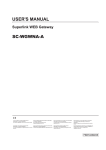
■ Header system
Outdoor unit: FDC155KXES6
Indoor unit: Combination of 6 units
[ Header pipe set : HEAD6-180-1 ´ 1 set]
[Total capacity: 208]
¥ Selecting piping size
Outdoor unit
FDCA155
Item
A
Indoor unit
A
a
b
c
d
e
f
Header
a
b
c
d
e
f
22
22
56
36
36
36
Remarks (1) Install the header so
that both the gas
pipe and liquid pipe
are horizontal and so
that branches are
horizontal.
Same as the outdoor unit piping size
Indoor unit piping size (22)
Indoor unit piping size (22)
Indoor unit piping size (56)
Piping size (mm)
Gas line Liquid line
¿15.88 ¿9.52
¿9.52 ¿6.35
¿9.52 ¿6.35
¿12.7 ¿6.35
Indoor unit piping size (36)
¿12.7 ¿6.35
Selection procedure
¥ Selection header pipe size
Item
Selection point
Header
Total indoor unit capacity
Liquid side
Horizontal
Horizontal
Floor
Model
HEAD6-180-1
Notes(1) Select the appropriate size of each pipe for the offset pipe
joints included with the header set.
(2) If it is necessary to adjust the diameter of the header and
indoor unit side piping, be sure to do so on the header
side.
Gas side
Horizontal
Floor
(2) It is not necessary to install a trap in the stand pipe.
-
244 -
(ii) Piping work
Piping connection position and the piping remove direction
● First remove the five screws ( mark) of the service panel and push it down into the direction of the arrow mark and then
remove it by pulling it toward you.
● The pipe can be laid in any of the following directions: side right, front, rear and downward.
● Remove a knock-out plate provided on the pipe penetration to open a minimum necessary area and attach an edging
material supplied as an accessory by cutting it to an appropriate length before laying a pipe.
● In laying pipes on the installation site, cut off the casing’s half blank that covers a hole for pipe penetration with nippers.
● If there is a risk of small animals entering from the pipe penetration part, close the part with some sealing material or the
like (to be arranged on the installer’s part).
● In the case of an installation using a collective drain system, use a port other than the bottom one to take out cables and
pipes. If the bottom port is used, seal it thoroughly so that drain water may not spill out.
● Use an elbow (to be arranged on the user’s part) to connect control valves to the piping.
● In anchoring piping on the installation site, give 1.5m or a longer distance between an outdoor unit and an anchoring point
where the piping is secured as illustrated below. (A failure to observe this instruction may result in a pipe fracture depending
on a method of isolating vibrations employed.)
Catch
For rear connection
Pipe fastening position
Over 1.5m
For front connection
For side right connection
For downward connection
Outdoor unit
a) On-site piping work
Important
● Please take care so that installed pipes may not touch components within a
CAUTION
unit.
If you tighten it without using
● During the pipe installation at site, keep the service valves shut all
double spanners, you may deform
the time.
the service valve, which can cause
● Give sufficient protections (compressed and brazed or by an adhesive tape)
an inflow of nitrogen gas into the
outdoor unit.
to pipe ends so that any water or foreign matters may not enter
the pipes.
● In bending a pipe, bend it to the largest possible radius (at least four times the pipe diameter). Do not bend a
pipe repeatedly to correct its form.
● An outdoor unit’s pipe and refrigerant piping are to be flare connected. Flare a pipe after engaging a flare nut onto it. A
flare size for R410A is different from that for conventional R407C. Although we recommend the use of flaring tools
developed specifically for R410A, conventional flaring tools can also be used by adjusting the measurement of protrusion
B with a protrusion control gauge.
● Tighten a flare joint securely with two spanners. Observe flare nut tightening torque specified in the table below.
B
H
Flarenut parallelside
measurement: H (mm)
Copper
pipe outer
H
diameter
¿6.35
17
¿9.52
22
26
¿12.7
¿15.88
29
A
Flared pipe end: A (mm)
Copper
0
pipe outer A -0.4
diameter
9.1
¿6.35
13.2
¿9.52
16.6
¿12.7
19.7
¿15.88
Copper pipe protrusion for flaring: B (mm)
Copper
In the case of a rigid (clutch) type
pipe outer
diameter With an R410A tool With a conventional tool
¿6.35
¿9.52
0 ~ 0.5
0.7 ~ 1.3
¿12.7
¿15.88
-
245 -
Fix both liquid and gas service valves at the valve main bodies as illustrated on the right, and then fasten them, applying
appropriate fastening torque.
Service valve size Tightening torque Tightening angle Recommended length
of a tool handle (mm)
(N-m)
(mm)
(¡ )
¿6.35 (1/4")
14 ~ 18
45 ~ 60
150
¿9.52 (3/8")
34 ~ 42
30 ~ 45
200
¿12.7 (1/2")
49 ~ 61
30 ~ 45
250
¿15.88(5/8")
68 ~ 82
15 ~ 20
300
Do not hold the valve cap area
with a spanner.
Use a torque wrench. If a torque wrench
is not available, fasten the flare nut
manually first and then tighten it further,
using the left table as a guide.
● Do not apply any oil on a flare joint.
● Blazing must be performed under a nitrogen gas flow. Without nitrogen gas, a large quantity of foreign matters
(oxidized film) are created, causing a critical failure from capillary tube or expansion valve clogging.
● Brazing of the service valve and the pipes should be performed while cooling the valve body with a wet towel.
● Perform flushing. To flush the piping, charge nitrogen gas at about 0.02MPa with a pipe end closed with a hand. When
pressure inside builds up to a sufficient level, remove the hand to flush. (in flushing a pipe, close the other end of the pipe
with a plug).
Operation procedure
q During the pipe installation at site, keep the service valves shut all the time.
w Blazing must be performed under a nitrogen gas flow. Without nitrogen gas, a large quantity of foreign matters
(oxidized film) are created, causing a critical failure from capillary tube or expansion valve clogging.
Plug the end of the pipe with tape, or other
material, and fill the pipe with nitrogen gas.
N2
Taping
Only use nitrogen gas (N2)
Nitrogen
Brazing
e Give sufficient protections (compressed and brazed or with an adhesive tape) so that water or foreign matters
may not enter the piping.
Flatten
Brazing
Adhesive tape
r Perform flushing. To flush the piping, charge nitrogen gas at about 0.02MPa with a pipe end closed with a hand. When
pressure inside builds up to a sufficient level, remove the hand to flush. (in flushing a pipe, close the other end of the pipe
with a plug).
Primary side
Station valve
Secondary side
0.02MPa
Hand
Nitrogen
gas
Relief valve
-
246 -
(iii) Air tightness test and air purge (Carry them out according to the following steps.)
Air tightness test
q Although an outdoor unit itself has been tested for air tightness at the factory, please check the connected pipes and
indoor units for air tightness from the check joint of the service valve on the outdoor unit side. While conducting a test,
keep the service valve shut all the time.
w Since refrigerant piping is pressurized to the design pressure of a unit
CAUTION
with nitrogen gas for testing air tightness, please connect instruments
Applying excessive pressure can
according the drawing below.
cause an inflow of nitrogen gas into
Under no circumstances should chlorine-based refrigerant, oxygen or any
an outdoor unit.
other combustible gas be used to pressurize a system
Keep the service valve shut all the time. Do not open it under any circumstances.
Be sure to pressurize all of the liquid, gas pipes.
e In pressurizing the piping, do not apply the specified level of pressure all at once, but gradually raise pressure.
a) Raise the pressure to 0.5 MPa, and then stop. Leave it for five minutes or more to see if the pressure
drops.
b) Then raise the pressure to 1.5 MPa, and stop. Leave it for five more minutes to see if the pressure drops.
c) Then raise the pressure to the specified level (4.15 MPa), and record the ambient temperature and the pressure.
d) If no pressure drop is observed with an installation pressurized to the specified level and left for
about one day, it is acceptable. When the ambient temperature changes 1°C, the pressure also changes approximately 0.01 MPa. The pressure, if changed, should be compensated for.
e) If a pressure drop is observed in checking e) and a) - d), a leak exists somewhere. Find a leak by applying bubble test
liquid to welded parts and flare joints and repair it. After repair, conduct an air-tightness test again.
r Always pull air from the pipes after the airtightness test.
Operation valve
Liquid pipe
To indoor unit
Nitrogen
gas
Gauge manifold
Lo
Hi
Lo knob
Hi knob
Gas pipe
Service point
(check joint)
Outdoor unit
Vacuuming
Please pull air from the check joints of the service valves on both liquid and gas sides.
<Work flow>
When the system has
remaining moisture inside or a leaky point,
the vacuum gauge indicator will rise.
Check the system for a
leaky point and then
draw air to create a vacuum again.
Airtighteness test completed
Please run the vacuum pump for
at least one hour after the vacuum
gauge shows -101kPa or lower.
(-755mmHg or lower)
Vacuuming begins
Vacuuming completed
Confirm that the vacuum gauge indicator does not rise after leaving the
system for an hour or more.
Vacuum gauge check
Fill refrigerant
-
247 -
CAUTION
Insufficient vacuuming
may result in poor performance falling short of the
design capacity, pipe clogging due to residue moisture and/or a compressor
failure.
Pay attention to the following points in addition to the above for the R410A and compatible machines.
To prevent a different oil from entering, please assign dedicated tools, etc. to each refrigerant type. Under no
circumstancescharge hose in particular be shared with other refrigerant types (R22, R407C, etc.).
Use a counterflow prevention adapter to prevent vacuum pump oil from entering the refrigerant system.
Compound pressure gauge Pressure gauge
Gauge manifold
(for R410A only)
Handle Hi
Charge hose
(for R410A only)
Check valve
Vacuum adapter
(for R410A only)
-101KPa (-755mmHg)
Handle Lo
Charge hose (for R410A only)
In-unit check joint
Gas operation valve
Charge port
Liquid operation valve
(with a charge port)
Vacuum
pump
● You can purge air with either liquid service valve or gas service valve.
When a vacuum air purge is completed, remove the valve rod cap nuts and open the service valves (both liquid and gas sides) as
illustrated below. After you have made sure that the valves are in the full-open position, tighten the cap nuts (for the valve rods and
charge ports).
Pin type
Hexagonal wrench type
Remove the hexagon cap nut, set it as illustrated
in the drawing below.
Hexagonal wrench
(M4)
Stopper
Open
Liquid/gas operation
Pin
Factory setting (close) Open
● Open the valve rod until it touches the stopper.
You need not apply force to push it further.
For tightening torque, refer to the table below.
Service valve size
(mm)
¿9.52 (3/8")
¿15.88(5/8")
Tightening torque
(N-m)
6~8
14 ~ 16
Cap tightening torque
(N á m)
20 ~ 30
30 ~ 40
Cap nut tightening torque
of check joint
(N á m)
10 ~ 12
10 ~ 12
¥ When an operation is completed, replace the cap nut and tighten it as before.
¥ Shaft operation, cap and cap nut is performed by excessive torque, it will become failure and
a cause of a leak, please follow a table.
-
248 -
(iv) Additional refrigerant charge
Additional refrigerant charge
Charge additional refrigerant in the liquid state.
Be sure to measure the quantity with a scale in adding refrigerant.
If you cannot charge all refrigerant with the outdoor unit lying idle, charge it with the unit running in the test run mode. (For
the test run method, please refer to Section 8)
If operated for a long time with insufficient refrigerant the compressor will be damaged. (In particular, when adding refrigerant during operation, complete the job within 30min.)
Fill this unit only with the standard amount of refrigerant (piping length 0m fill quantity).
Determine the amount of refrigerant to be charged additionally using the following formula and put down the amount of
refrigerant added on the refrigerant charge volume recording plate provided on the back of the side panel.
● Adding additional refrigerant
Charge additional refrigerant according to the size and length of the liquid piping
Determine additional charge volume by rounding to the nearest 0.1 kg.
Item
Capacity
112, 140, 155
length for Additional charge volume (kg) Refrigerant volume InstallationÕs pipe length (m)
Standard refrigerant Pipe
baseline
charge per meter of refrigerant piping charged for shipment covered without additional
charge volume (kg) volume (m)
refrigerant charge
at the factory (kg)
(liquid pipe)
5.0
30
3.38
0
0.054
Refrigerant pipe size
¿9.52
¿6.35
Additional charge volume (kg) 0.054
0.022
● A standard refrigerant charge volume means a refrigerant charge volume for an installation with 0m long refrigerant
piping.
● This unit contains factory charged refrigerant covering 30m of refrigerant piping and additional refrigerant
charge on the installation site is not required for an installation with up to 30m refrigerant piping.
When refrigerant piping exceeds 30m, additionally charge an amount calculated from the pipe length and the above table
for the portion in excess of 30m.
Formula to calculate the volume of additional refrigerant required
Model112,140,155
Total refrigerant (necessary) charge volume (kg) = Standard refrigerant charge 3.38kg + ¿9.52 Total length of liquid
pipes (m) x 0.054(kg/m) + ¿6.35 Total length of liquid pipes (m) x 0.022
Additional charge volume (kg) = Total refrigerant (necessary) charge volume (kg) - Factory charged volume 5 (kg)
* When an additional charge volume calculation result is negative, it is not necessary to charge refrigerant additionally.
● If the pipe length is shorter than 5 m, you should charge a reduced refrigerant volume.
Recover the refrigerant from the system and charge the standard refrigerant charge + the amount for
liquid pipe.
Pay attention to the following points in addition to the above for the R410A and compatible machines.
● To prevent a different oil from entering, please assign dedicated tools, etc. to each refrigerant type. Under no circumstances
must a gauge manifold and a charge hose in particular be shared with other refrigerant types (R22, R407C, etc.).
● Refrigerant types are indicated by color at the top of the cylinder. (Pink for R410A). Always confirm this.
● Do not use a charge cylinder under any circumstances. There is a danger that the composition of the refrigerant will
change when R410A is transferred to a cylinder.
● When charging refrigerant, use liquid refrigerant from a cylinder.
● Use a Adverse current prevention adapter so that vacuum pump oil does not mix in a system.
-
249 -
(v) Heat insulation for prevention of dew condensation
q Dress refrigerant pipes (both gas and liquid pipes) for heat insulation and prevention of dew condensation.
Improper heat insulation/anti-dew dressing can result in a water leak or dripping causing damage to household effects,
etc.
w Use a heat insulating material that can withstand 120°C or a higher temperature. Poor heat insulating capacity can cause
heat insulation problems or cable deterioration.
● All gas pipes must be securely heat insulated in order to prevent damage from dripping water that comes from the
condensation formed on them during a cooling operation or personal injury from burns because their surface can reach
quite a high temperature due to discharged gas flowing inside during a heating operation.
● Wrap indoor units’ flare joints with heat insulating parts (pipe cover) for heat insulation (both gas and liquid pipes).
● Give heat insulation to both gas and liquid side pipes. Bundle a heat insulating material and a pipe tightly together so
that no gaps may be left between them and wrap them together with a connecting cable by a dressing tape.
● Although it is verified in a test that this air conditioning unit shows satisfactory performance under JIS condensation
test conditions, both gas and liquid pipes need to be dressed with 10-20mm heat insulation materials additionally above
the ceiling where relative humidity exceeds 70%.
Wires for connecting indoor
and outdoor units
Liquid piping
Exterior tape
Band (accessory)
Pipe cover (accessory)
Gas piping
Insulation
(e) Drainage
● Where drain water from the outdoor unit causes problems, implement drain piping with drain elbows and drain grommets,
which are supplied separately as option parts.
● There are 3 holes in the bottom panel of the outdoor unit to drain condensation.
● Where condensate is guided to a drain, install the unit on a flat base (an option part supplied separately) or concrete blocks.
● Connect a drain elbow as illustrated and plug the other holes with grommets.
Drain elbow (1 piece)
Hard general-purpose PVC pipe available on the market: VP-16
-
250 -
Drain grommets
(2 pieces)
(5) Electrical wiring work
Electrical installation work must be performed by an electrical installation service provider qualified by a power provider of the
country.
Electrical installation work must be executed according to the technical standards and other regulations applicable to electrical
installations in the country.
Please install an earth leakage breaker without fail. The installation of an earth leakage breaker is compulsory in
order to prevent electric shocks or fire accidents.
(Since this unit employs inverter control, please use an impulse withstanding type to prevent an earth leakage breaker’s
false actuation.)
Please note
a) Use only copper wires.
Do not use any supply cord lighter than one specified in parentheses for each type below.
- braided cord (code designation 60245 IEC 51), if allowed in the relevant part 2;
- ordinary tough rubber sheathed cord (code designation 60245 IEC 53);
- flat twin tinsel cord (code designation 60227 IEC 41)
- ordinary polyvinyl chloride sheathed cord (code designation 60227 IEC 53).
Please do not use anything lighter than polychloroprene sheathed flexible cord (cord designation 60245 IEC57) for
supply cords of parts of appliances for outdoor use.
b) Use separate power supplies for the indoor and outdoor units.
c) The power supplies for indoor units in the same system should turn on and off simultaneously.
d) Ground the unit. Do not connect the grounding wire to a gas pipe, water pipe, lightning rod or telephone grounding wire.
A grounding wire must be connected before connecting the power cable. Provide a grounding wire longer than the power
cable.
If improperly grounded, an electric shock or malfunction may result.
e) The installation of an impulse with standing type earth leakage breaker is necessary. A failure to install
an earth leakage breaker can result in an accident such as an electric shock or a fire. Do not turn on the power until the
electrical work is completed. Be sure to turn off the power when servicing.
f) Please do not use a condensive capacitor for power factor improvement under any circumstances. (It does not improve
power factor, while it can cause an abnormal overheat accident)
g) For power supply cables, use conduits.
h) Please do not lay electronic control cables (remote control and signaling lines) and other high current
cables together outside the unit. Laying them together can result in malfunctioning or a failure of the unit due to
electric noises.
i) Power cables and signaling lines must always be connected to the terminal block and secured by cable fastening clamps
provided in the unit.
j) Fasten cables so that they may not touch the piping, etc.
k) When cables are connected, please make sure that all electrical components within the electrical
component box are not free or not loose on the terminal connection and then attach the cover securely.
(Improper cover attachment can result in malfunctioning or a failure of the unit, if water penetrates into the box.)
Wiring system diagrams
Power source (Outdoor unit side)
220/240V ~ 50Hz
220V ~ 60Hz
380/415 3N ~ 50Hz
380V 3N ~ 60Hz
Power source (Indoor unit side)
220/240V ~ 50Hz
220V ~ 60Hz
(The example of combination)
LáN
or
L1áL2áL3áN
Circuit breaker for cabling
Earth leakage breaker
grounding wire
Signal line (for indoor units)
Earth
leakage
breaker
Circuit
breaker
for cabling
Indoor unit
Outdoor unit
AáB
Signal line (between outdoor and indoor units < >)
L AáB
á
N XáY
L AáB
á
N XáY
L AáB
á
N XáY
XáY
XáY
grounding wire
Remote control wire
XáY
Remote
control
CAUTION
If the earth leakage breaker is exclusively for ground fault protection,
then you will need to install a circuit breaker for wiring work.
-
251 -
Method of connecting power cables
q Method of leading out cables
● As shown on the drawing in Section 4-2, cables can be laid through the front, right, left or bottom casing.
● In wiring on the installation site, cut off a half-blank covering a penetration of the casing with nippers.
● In the case of an installation using a collective drain system, use a port other than the bottom one to take out cables and
pipes.
If the bottom port is used, seal it thoroughly so that drain water may not spill out.
w Notabilia in connecting power cables
● Connect the ground wire before you connect the power cable. When you connect a grounding wire to a terminal block,
use a grounding wire longer than the power cable so that it may not be subject to tension.
● Do not turn on power until installation work is completed. Turn off power to the unit before you service the unit.
● Always connect power cables to the power terminal block.
● To connect a cable to the power terminal block, use a round crimp contact terminal.
If two cables are to be connected to one terminal, arrange cables in such a manner that you put their crimp contact
terminals together back to back. Further, put the thinner cable above the thicker one in arranging cables for such
connection.
● Use specified wires in wiring, and fasten them securely in such a
Round crimp
manner that the terminal blocks are not subject to external force.
Wire
contact terminal
● In fastening a screw of a terminal block, use a correct-size driver.
Fastening a screw of a terminal block with excessive force can break
the screw.
Terminal block Crimp
contact terminal
● When electrical installation work is completed, make sure that all
Diameter of a cable:thin
electrical components within the electrical component box are free
of loose connector coupling or terminal connection.
Diameter of a cable:thick
Power source specifications
q Outdoor unit power source (Indoor unit is another power source.)
Model
Power source
Earth wire
Wire length Moulded-case circuit breaker (A)
Cable size for
Earth leakage breaker
power source (mm2)
(m)
Size (mm2) Screw type
Rated current Switch capacity
112KXEN6
Single-phase
140KXEN6 220/240V 50Hz
155KXEN6 220V 60Hz
112KXES6
140KXES6
155KXES6
Three-phase
380/415V 50Hz
380V 60Hz
8
32
40
50
40A, 30mA
less than 0.1 sec
2
M5
3.5
46
20
30
20A, 30mA
less than 0.1 sec
2
M4
w Indoor unit power source (Outdoor unit is another power source.) & signal line
Moulded-case circuit breaker (A)
Signal line (mm2)
Combined total capacity Cable size for
power source (mm2) Wire length (m) Rated current Switch capacity Earth leakage breaker outdoor-indoor indoor-indoor
of indoor units
less than 7A
2
less than 11A
3.5
less than 12A
5.5
33
less than 16A
5.5
24
21
20
30
30
20A, 30mA
less than 0.1 sec
30A, 30mA
less than 0.1 sec
2 core 2 0.75*
*Please use a shielded cable.
Please note
a) The method of laying cables has been determined pursuant to the Japanese indoor wiring regulations (JEAC8001).
(Please adapt it to the regulations in effect in each country)
b) Wire length in the table above is the value for when the indoor unit is connect to the power cable in series also the wire
size and minimum length when the power drop is less than 2% are shown. If the current exceeds the value in the table
above, change the wire size according to the indoor wiring regulations. (Please adapt it to the regulations in effect in each
country)
c) For details, please refer to the installation manual supplied with the indoor unit.
-
252 -
How to connect signal cables
The communication protocol can be choosen from following two types. One of them is the conventional Superlink (hereinafter previous SL) and the other is the new Superlink II (hereinafter new SL) . These two communication protocols have the
following advantages and restrictions, so please choose a desirable one meeting your installation conditions such as connected indoor units and centralized controller. When signal cables are connected into a network involving outdoor units,
indoor units or centralized control equipment that do not support new SL, please select communications in the previous SL
mode, even if the refrigerant system is separated from theirs.
Communication protocol
Outdoor unit setting (SW5-5)
No. of connectable indoor units in a network
No. of connectable outdoor units in a network
Signal cable (total length)
Signal cable (furthest length)
Connectable units to a network
Conventional communication protocol (previous SL) New communication protocol (new SL)
OFF (factory setting)
ON
Max. 128
Max. 48
Max. 32
Max. 48
Up to 1500m (When 0.75mm2 shielded cable used)
Up to 1000m
Up to 1000m (When 1.25mm2 shielded cable used)
Up to 1000m
Up to 1000m
Units not supporting new SL (FD A KXE4 series)
Units supporting new SL (FD
KXE6 series)
Units supporting new SL (FD
KXE6 series)
Can be used together. (*1)
*1 New SL supporting units and non-supporting units cannot be used together in a same refrigerant system.
● A signal cable system is operated at DC5V, so never connect it to the power source 220/240V or 380/
415V. If the power source is applied, a protective fuse provided on the board will be actuated. If the protective fuse is
actuated, follow the procedure set out below.
(1) Turn off power and make sure that 220/240V or 380/415V is not applied to signaling wires.
(2) In the case of an indoor unit, switch from CNK1 to CNK2 and cut the jumper line JSL1.
(3) In the case of an outdoor unit, switch from CNX1 to CNX2 and cut the jumper line J10.
(4) Check signal cable terminal block resistance before you turn on power. If the resistance value is 100 ohms or less,
there is possibility that a power cable is connected to a signal cable terminal block.
A typical resistance value is [46000 / (No. of connected FD A
KXE4 series units x 5) + (No. of
connected FD
KXE6 series units x 9)].
If the resistance value is 100 ohms or less, tentatively detach signal cables and thus, divide the network into more than
one block (to reduce the number of indoor units connected in a network) to check for cabling errors in each such block.
Indoor and outdoor signal wires
● Connect the signal line between indoor unit and outdoor unit to A1 and B1.
● Connect the signal line between outdoor units to A2 and B2.
● Please use a shielded cable for a signal line and connect a shielding earth at all the indoor units and outdoor units.
(1) When one outdoor unit is used.
Outdoor signal line
terminal block
(2) When plural outdoor units are used
A1 B1
Indoor signal line
terminal block
A B
A B
A B
Any of the connections in the following illustration can be made.
A
B
A1
B1
Outdoor unit
Outdoor unit
A1áB1 A2áB2
A1áB1 A2áB2
A1áB1 A2áB2
Indoor unit
Indoor unit
Indoor unit
Indoor unit
Indoor unit
Indoor unit
A
B
Indoor and outdoor signal lines do not have a polarity.
A1
B1
Outdoor unit
A
B
A
B
A
B
A
B
Outdoor unit
A
B
Important
Outdoor unit
Loop wiring prohibited.
Outdoor unit Outdoor unit Outdoor unit Outdoor unit
Indoor unit
Indoor unit
Indoor unit
Indoor unit
Indoor unit
Indoor unit
Refrigerant pipe
A
B
Signal line
(1) The signal lines can also be connected using the
method shown below.
Outdoor unit
Network connector
Indoor unit Indoor unit
-
253 -
Indoor unit Indoor unit
The signal lines cannot form a
loop, so the wirings shown as
....... in the diagram are
prohibited.
Power cable and signal line connection
Signal terminal block
Network connector
Cable clamp
Earth wire is giving slack.
● It holds cables in place and protect the terminal connection
from external force.
● Give adequate slack to cables in fastening them.
M4 screw
Outgoing cable direction
● As like the refrigerant pipe, it can be let out in any of the
following directions: side right, front, rear and downward.
Wiring label
● The wiring label is attached on the back side of the service
panel.
*1 *2
*1 Signal line between the indoor unit and the outdoor unit.
*2 Signal line between the outdoor units.
Attention
● For cabling of the signal line terminal
● For cabling of the power source terminal block, use
block, use crimp terminals of the
figure shown below.
crimp terminals of the figure shown below.
FDC112 ~ 155KXEN6 (Single-phase)
12 mm or less
For M5
FDC112 ~ 155KXES6 (Three-phase)
9.5 mm or less
Remote controller wiring specifications
(1) For the remote controller the standard wire is 0.3mm2 2 cores.
The max. length is up to 600m. When the wire is more than 100m
long, use the wire shown in the table.
For M4
6.6 mm or less
Length (m)
100 to 200
to 300
to 400
to 600
For M3.5
Wire size
0.5mm2 2 cores
0.75mm2 2 cores
1.25mm2 2 cores
2.0mm2 2 cores
(6) Controller settings
(i)
Unit address setting
This control system controls the controllers of more than one air conditioner's outdoor unit, indoor unit and remote control
unit through communication control, using the microcomputers built in the respective controllers. Address setting needs to
be done for both outdoor and indoor units. Turn on power in the order of the outdoor units and then the indoor units.
Use 1 minute as the rule of thumb for an interval between them.
The communication protocol can be choosen from following two types. One of them is the conventional Superlink (hereinafter
previous SL) and the other is the new Superlink II (hereinafter new SL). These two communication protocols have their
advantages and restrictions as summarized in a table in “6. ELECTRICAL WIRING WORK” so please choose a desirable
one meeting your installation conditions such as connected indoor units and centralized controller.
When signal cables are connected into a network involving outdoor units, indoor units or centralized control equipment that
do not support new SL, please select communications in the previous SL mode, even if the refrigerant system is separated
from theirs.
When communication is established after setting addresses, check the communication protocol with the
7 segment display panel of the outdoor unit.
-
254 -
● Address setting methods
The following address setting methods can be used. The procedure for automatic address setting is different from the
conventional one.
Please use the automatic address setting function after reading this manual carefully.
new SL
previous SL
Automatic Manual Automatic Manual
Communication protocol
Address setting method
When only one refrigerant system is involved
(signal lines do not link with plural refrigerant systems)
When plural refrigerant systems are linked
with signal lines
(e.g., to implement centralized controller)
OK
OK
OK
OK
Case 1 When signal lines linking plural refrigerant
systems are provided between outdoor units.
OK*1
OK
OK
Case 2 When signal lines linking plural refrigerant
systems are provided between indoor units.
*2
OK
OK
*1 Do not connect the signal line between outdoor units to A1 and B1. This may interrupt proper address setting. (Case 3)
Do not connect the signal line between indoor unit and outdoor unit to A2 and B2. This may interrupt proper address
setting. (Case 4)
*2 In Case 2, automatic address setting is not available. Set addresses manually.
Outdoor unit
Outdoor unit
Outdoor unit
Outdoor unit
Outdoor unit
Outdoor unit
Network connector
A1áB1 A2áB2
A1áB1 A2áB2
A1áB1 A2áB2
A1áB1 A2áB2
A1áB1 A2áB2
Indoor unit
Indoor unit
Indoor unit
Indoor unit
Indoor unit
Indoor unit
A
B
Signal line
Network connector
A1áB1 A2áB2
Indoor unit
Indoor unit
Indoor unit
A
B
A
B
A
B
A
B
A
B
Refrigerant pipe
A
B
Indoor unit
A
B
A
B
Indoor unit
A
B
CASE 1
Outdoor unit
A
B
Indoor unit
A
B
CASE 2
Outdoor unit
Outdoor unit
Outdoor unit
Outdoor unit
Outdoor unit
Network connector
Network connector
A1áB1 A2áB2
A1áB1 A2áB2
A1áB1 A2áB2
A1áB1 A2áB2
A1áB1 A2áB2
A1áB1 A2áB2
Indoor unit
Indoor unit
Indoor unit
Indoor unit
Indoor unit
Indoor unit
A
B
A
B
A
B
A
B
Indoor unit
Indoor unit
Indoor unit
Indoor unit
A
B
A
B
A
B
A
B
A
B
A
B
Indoor unit
Indoor unit
A
B
A
B
CASE 3
CASE 4
Incorrect cable connection
(The signal line between outdoor units is connected to
A1 and B1)
Incorrect cable connection
(The signal line between indoor unit and outdoor units
is connected to A2 and B2)
● Address No. setting
Set SW1 through 4 and SW5-2 provided on the PCB and SW1 & 2 provided on the outdoor unit PCB as shown in the
drawings below.
SW1, 2 (blue)
SW3, 4 (green)
SW5-2
SW1, 2 (green)
Indoor PCB
Outdoor PCB
2 3
4
5 6
For tenÕs place
0 1
7 8
9
2 3
7 8
SW2 (SW4)
5 6
9
0 1
4
SW1 (SW3)
For setting indoor No. (The tenÕs and oneÕs)
For setting outdoor No. (The tenÕs and oneÕs)
Indoor No. switch (The hundredÕs Place) [OFF : 0, ON : 1]
For setting outdoor No. (The tenÕs and oneÕs)
By inserting a flat driver
(precision screw driver) into
this groove and turn the arrow
to point a desired number.
For oneÕs place
-
255 -
● Summary of address setting methods (figures in [
] should be used with previous SL)
Units supporting new SL
Indoor unit address setting
Indoor No. switch
Manual address setting
(previous SL/new SL)
Units NOT supporting new SL
Outdoor unit address setting
Indoor unit address setting
Outdoor unit address setting
Outdoor No. switch Outdoor No. switch Indoor No. switch Outdoor No. switch Outdoor No. switch
000 ~ 127 [47] (*1)
00 ~ 31[47]
00 ~ 31[47]
00 ~ 47
00 ~ 47
00 ~ 47
000
49
49
49
49
49
000
49
00 ~ 31
Automatic address setting for
single refrigerant system installation
(previous SL/new SL)
Automatic address setting for
multiple refrigerant systems installation
(with new SL only)
(*1) Do not set numbers other than those shown in the table, or an error may be generated.
Note: When units supporting new SL are added to a network using previous SL such as one involving FD
A
KXE4
series units, choose previous SL for the communication protocol and set addresses manually.
● An outdoor unit No., which is used to identify which outdoor unit and indoor units are connected in a refrigerant system,
is set on outdoor unit PCB and indoor unit PCB. Give the same outdoor unit No. to all outdoor unit and indoor units
connected in same refrigerant system.
● An indoor unit No. is used to identify individual indoor units. Assign a unique number that is not assigned to any other
indoor units on the network.
Unless stated otherwise, the following procedures apply, when new SL is chosen for the communication protocol.
When previous SL is chosen, use figures shown in [ ] in carrying out these procedures.
Manual address setting
Generally applicable to new SL/previous SL, use figures in [ ] with previous SL.
q Outdoor unit address setting
Set as follows before you turn on power. Upon turning on power, the outdoor unit address is registered.
Set the Outdoor Unit No. switch to a number 00 - 31 [in the case of previous SL: 00 - 47].
Set a unique number by avoiding the numbers assigned to other outdoor units on the network.
w Indoor unit address setting
Set as follows before you turn on power. Upon turning on power, the indoor unit address is registered.
Set the Indoor Unit No. switch to a number 000 - 127 [in the case of previous SL: 00 - 47].
Set the Outdoor Unit No. switch to the outdoor unit No. of the associated outdoor unit within the range of 00 - 31 [in
the case of previous SL: 00 - 47].
Set a unique number by avoiding the numbers assigned to other indoor units on the network.
e Turn on power in order from the outdoor unit to indoor units. Give a one-minute or longer interval for them.
* When there are some units not supporting new SL connected in the network, set SW5-5 to ON to choose the previous
SL communication mode.
In the case of previous SL, the maximum number of indoor units connectable in a network is 48.
Automatic address setting
Generally applicable to new SL/previous SL, use figures in [ ] with previous SL.
With new SL, you can set indoor unit addresses automatically even for an installation involving multiple refrigerant systems
connected with same network, in addition to the conventional automatic address setting of a single refrigerant system installation.
However, an installation must satisfy some additional requirements such as for wiring methods, so please read this manual
carefully before you carry out automatic address setting.
(1) In the case of a single refrigerant system installation
(Generally applicable to new SL/previous SL, use figures in [ ] with previous SL.)
q Outdoor unit address setting
Set as follows before you turn on power.
Make sure that the Outdoor Unit No. switch is set to 49 (factory setting)
w Indoor unit address setting
Set as follows before you turn on power.
Make sure that the Indoor Unit No. switch is set to 000 [in the case of previous SL: 49] (factory setting)
Make sure that the Outdoor Unit No. switch is set to 49 (factory setting)
e Turn on power in order from the outdoor unit to indoor units. Give a one-minute or longer interval for them. Unlike the
procedure set out in (2) below, you need not change settings from the 7 segment display panel.
r Make sure that the number of indoor units indicated on the 7 segment display panel agrees with the number of the indoor
units that are actually connected to the refrigerant system.
-
256 -
(2) In the case of a multiple refrigerant systems installation
(Applicable to new SL only. In the case of previous SL, set addresses with some other method.)
(This option is available when the interconnection wiring among refrigerant systems is on the outdoor side and new SL is
chosen as the communication protocol.)
Address setting procedure (perform these steps for each outdoor unit)
[STEP1] (Items set before turning on power)
㽲 Outdoor unit address setting
Set as follows before you turn on power.
Set the Outdoor Unit No. switch to a number 00 - 31. Set a unique number by avoiding the numbers assigned to other
outdoor units on the network.
ԙ Indoor unit address setting
Set as follows before you turn on power.
Make sure that the Indoor Unit No. switch is set to 000 (factory setting)
Make sure that the Outdoor Unit No. switch is set to 49 (factory setting)
㽴 Isolate the present refrigerant system from the network.
Disengage the network connectors (white 2P) of the outdoor units. (Turning on power without isolating each refrigerant
system will result in erroneous address setting.)
[STEP2] (Power on and automatic address setting)
ԛ Turn on power to the outdoor units and indoor units connected in one superlink network system.
Turn on power in order from outdoor units to indoor units. Give a one-minute or longer interval for them.
Ԝ Select “1” in P31 on the 7 segment display panel of each outdoor unit to start automatic address setting.
ԝ Input the starting address and the number of connected indoor units.
Input the starting address of indoor unit in P32 on the 7 segment display panel of each outdoor unit connected in one
superlink network system.
Ԟ When a starting address of indoor unit is inputted, the indication of 7 segment display will switch to P33 automatically.
Input the number of connected indoor units in P33 on the 7 segment display panel of each outdoor unit connected
in one superlink network system.
When the number of connected indoor units is inputted, the indication of 7 segment display will switch to “AUX” and
start blinking.
[STEP3] (Automatic address setting completion check)
ԟ Indoor unit address determination
When the indoor unit addresses are all set, the indication of 7 segment display will switch to “AUE” and start blinking.
If an error is detected in this process, the display will show “A٤٤” ,check the 7 segment display of each outdoor unit.˴
Depending on the number of connected indoor units, it may take about 30 minutes before the indoor unit addresses are
all set.
[STEP4] (Network definition setting)
Ԡ Network connection
When you have confirmed an “AUE” indication on the display of each outdoor unit, engage the network connectors
again.
ԡ Network polarity setting
After you have made sure that the network connectors are engaged in ԟ, select and enter “1” in P34 on the
7 segment display panel of any outdoor unit (on only 1 unit) to specify network polarity.
Ԣ Network setting completion check
When the network is defined, “End” will appear on the 7 segment display panel. An “End” indication will go off, when
some operation is made from the 7 segment display panel or 3 minutes after.
-
257 -
(1) Installation of indoor unit
(a) Ceiling cassete-4 way type (FDT)
(i)
Selection of installation location for the indoor unit
q Select the suitable areas to install the unit under approval of the user.
• Areas where the indoor unit can deliver hot and cold wind sufficiently. Suggest to the user to use a circulator the ceiling
height is over 3m to avoid warm air being accumulated on the ceiling.
• Areas where there is enough space to install and service.
• Areas where it can be drained properly. Areas where drain pipe descending slope can be taken.
• Areas where there is no obstruction of airflow on both air return grille and air supply port.
• Areas where fire alarm will not be accidentally activated by the air conditioner.
• Areas where the supply air does not short-circuit.
• Areas where it is not influenced by draft air.
• Areas not exposed to direct sunlight.
• Areas where dew point is lower than around 28ºC and relative humidity is lower than 80%.
This indoor unit is tested under the condition of JIS (Japan Industrial Standard) high humidity condition and
confirmed there is no problem. However, there is some risk of condensation drop if the air conditioner is operated
under the severer condition than mentioned above.
If there is a possibility to use it under such a condition, attach additional insulation of 10 to 20mm thick for entire
surface of indoor unit, refrigeration pipe and drain pipe.
• Areas where TV and radio stays away more than 1m. (It could cause jamming and noise.)
• Areas where any items which will be damaged by getting wet are not placed such as food, table wares, server, or
medical equipment under the unit.
• Areas where there is no influence by the heat which cookware generates.
• Areas where not exposed to oil mist, powder and/or steam directly such as above fryer.
• Areas where lighting device such as fluorescent light or incandescent light doesnít affect the operation.
(A beam from lighting device sometimes affects the infrared receiver for the wireless remote controller and the air
conditioner might not work properly.)
w Check if the place where the air conditioner is installed can hold the weight of the unit. If it is not able to hold, reinforce
the structure with boards and beams strong enough to hold it. If the strength is not enough, it could cause injury due to
unit falling.
e If there are 2 units of wireless type, keep them away for more than 6m to avoid malfunction due to cross communication.
r When plural indoor units are installed nearby, keep them away for more than 4 to 5m.
(
)
Space for installation and service
● When it is not possible to keep enough space between indoor unit and wall or between indoor units, close the air supply
port where it is not possible to keep space and confirm there is no short circuit of airflow.
● Install the indoor unit at a height of more than 2.5m above the floor.
4000 to 5000mm or more
Indoor unit
Indoor unit
Ceiling
Wall
surface
1000mm or more
2500mm or more
Decorative panel
1000mm or more
Obstacle
Floor
-
171 -
Indoor unit power source
Outdoor unit power source
Indoor unit
(indoor/outdoor No.SW)
Outdoor unit
(outdoor No.SW)
Network connectors
STEP3
STEP4
Ñ
Ñ
Ñ
Ñ
q 01,02(Ex)
Ñ
Ñ
Ñ
e Disconnect
Ñ
Ñ
w OFF
STEP1
r ON
q OFF
w indoor000/outdoor 49
r ON
(factory setting)
(each outdoor unit)
Start automatic address
setting
STEP2
Set the number of
indoor unit
o Connect
(each outdoor unit)
t Select ÒAutomatic
Address StartÓ
on each outdoor unit.
y outdoor 01:[01](EX)
outdoor 02:[04](EX)
u outdoor 01:[03](EX)
outdoor 02:[03](EX)
Set starting address
Ñ
Ñ
Ñ
Ñ
Ñ
Ñ
Ñ
!0 Set in P34 on the 7
Ñ
Polarity setting
u [AUX] (Blink)
7 segment display
[STEP1]
segment display
panel of any outdoor unit.
i ÒAUEÓ(blink), or
ÒAÓ in error events. !1 [End]
[STEP2]
Outdoor unit [01]
Outdoor unit [02]
Outdoor unit [01]
Outdoor unit [02]
Start [01]
Number [03]
Start [04]
Number [03]
Refrigerant pipe
Indoor unit
Indoor unit
Indoor unit
(00) + 01
Indoor unit
(00) + 04
Indoor unit
Indoor unit
Indoor unit
(01) + 01
Indoor unit
(01) + 04
Indoor unit
Indoor unit
Indoor unit
(02) + 01
Indoor unit
(02) + 04
Signal line
[STEP3]
[STEP4]
Outdoor unit [01]
Outdoor unit [02]
Outdoor unit [01]
Polarity
setting
Outdoor unit [02]
Indoor unit
01
Indoor unit
04
Indoor unit
01
Indoor unit
04
Indoor unit
02
Indoor unit
05
Indoor unit
02
Indoor unit
05
Indoor unit
03
Indoor unit
06
Indoor unit
03
Indoor unit
06
• Within a refrigerant system, indoor units are assigned addresses in the order they are recognized by the outdoor unit.
Therefore, they are not necessarily assigned addresses in order from the nearest to the outdoor unit first as depicted in
drawings above.
• Make sure that power has been turned on to all indoor units.
• When addresses are set, you can have the registered indoor unit address No.’s and the outdoor unit address No. displayed on
the remote control unit by pressing its Inspection switch.
• Automatic address setting can be used for an installation in which prulal indoor units are controlled from one remote
control unit.
• Once they are registered, addresses are stored in microcomputers, even if power is turned off.
• If you want to change an address after automatic address setting, you can change it from the remote control unit with its
“Address Change” function or by means of manual setting. Set a unique address by avoiding the address assigned to other
indoor unit on the network when the address is changed.
• Do not turn on power to centralized control equipment until automatic address setting is completed.
• When addresses are set, be sure to perform a test run and ensure that you can operate all indoor and outdoor units normally.
Also check the addresses assigned to the indoor units.
-
258 -
Address change (available only with new SL)
“Address Change” is used, when you want to change an indoor unit address assigned with the “Automatic
Address Setting” function from a remote control unit.
Accordingly, the conditions that permit an address change from a remote control unit are as follows.
Indoor unit address setting
Outdoor unit address setting
Indoor No.SW
Outdoor No.SW
Automatic address setting forsingle refrigerant system installation
000
49
49
Automatic address setting for multiple refrigerant systems installation
000
49
00 ~ 31
If ÒCHANGE ADD.
Outdoor No.SW
Ó is selected with some addresses falling outside these conditions, the following indication will appear
for 3 seconds on the remote controller ÓINVALID OPERÓ .
Operating procedure
1) When single indoor unit is connected to the remote controller.
Item
1 Address change
mode
Operation
Display
[CHANGE ADD. ]
q Press the AIR CON No. switch for 3 seconds or longer.
w Each time when you press the switch, the display indication will be switched. [CHANGE ADD. ]
[MASTER I/U ]
e Press the Set switch when the display shows ÒCHANGE ADD. Ó
[I/U 001 O/U 01] (1sec)
and then start the address change mode, changing the display indication to the /[ SET I/U ADD.] (1sec)
ÒIndoor Unit No. SettingÓ screen from the currently assigned address.
/[I/U 001 ] (Blink)
[I/U
000 ]
r Set a new indoor unit No. with the switch.
2 To set a new
[I/U
001 ]
A
number
indicated
on
the
display
will
increase
or
decrease
by
1
upon
indoor unit No.
[I/U 002 ]
pressing the or switch respectively.
á á á
[I/U 127 ]
[I/U 002] (2sec)
t After selecting an address, press the Set switch, and then the indoor unit
address No. is defined.
[I/U 002] (2sec Lighting)
y After showing the defined indoor address No. for 2 seconds, the display will
3 To set a new
/[ SET O/U ADD.] (1sec)
outdoor unit No. change to the ÒOutdoor Address No. SettingÓ screen.
/[O/U 01 ] (Blink)
The currently assigned address is shown as a default value.
[O/U 00 ]
u Set a new outdoor unit No. with the switch.
[O/U 01 ]
A number indicated on the display will increase or decrease by 1 upon
[O/U 02 ]
pressing the or switch respectively.
á á á
[O/U 31 ]
i After selecting an address, press the Set switch, and then the outdoor unit No. [I/U 002 O/U 02] (2sec Lighting)
/[SET COMPLETE] (2sec Lighting)
and the indoor unit No. are defined.
/Returns to normal condition.
-
259 -
2) When plural indoor units are connected to the remote controller.
When plural indoor units are connected, you can change their addresses without altering their cable connection.
Item
Operation
Display
[CHANGE ADD ]
1 Address change q Press the AIR CON Unit No. switch for 3 seconds or longer.
mode
w Each time when you press the switch, the display indication will be switched. [CHANGE ADD ]
[MASTER I/U ]
e Press the Set switch when the display shows ÒCHANGE ADD.
Ó
The lowest indoor unit No. among the indoor units connected to the remote
control unit will be shown.
2 Selecting an
r Pressing the switch will change the display indication cyclically to show the
indoor unit to be
unit
changed address
No.Õs of the indoor units connected to the remote controller and the unit No.Õs
of the outdoor units connected with them.
t Then the address No. of the indoor unit to be changed is determined and the
screen switches to the display Ò SET I/U ADD.Ó
3 Setting a new
indoor unit No.
y Set a new indoor unit No. with the
switch.
A number indicated on the display will increase or decrease by 1 upon
pressing the or switch respectively.
u After selecting an address, press the Set switch. Then the address No.of the
indoor unit is determined.
[ SELECT I/U] (1sec)
/[I/U 001 O/U 01 ] (Blink)
[I/U 001 O/U 01 ]
[I/U 002 O/U 01 ]
[I/U 003 O/U 01 ]
á á á
[I/U 016 O/U 01 ]
[ SET I/U ADD.] (1sec)
/[I/U 001 ] (Blink)
[I/U 000 ]
[I/U 001 ]
[I/U 002 ]
á á á
[I/U 127 ]
[I/U 002] (2sec)
i The display will indicate the determined indoor address No. for 2 seconds and [I/U 002] (2sec lighting)
4 Setting a new
/[ SET O/U ADD.] (1sec)
then switch to the Ò SET O/U ADD.Ó screen.
outdoor unit No.
/[O/U 01 ] (Blink)
A default value shown on the display is the current address.
[O/U
00 ]
o Set a new outdoor unit No. with the switch.
[O/U 01 ]
A number indicated on the display will increase or decrease by 1 upon
[O/U 02 ]
pressing the or switch respectively.
á á á
[O/U 31 ]
!0 After selecting an address, press the Set switch.
[I/U 002 O/U 02](2sec lighting)
/[ SELECT](1sec lighting)
/[I/U SELECTION ](lighting)
!1 If you want to continue to change addresses, return to step r.
[Press the switch](1sec)
/[SET COMPLETE]
(2~10seclighting)
!2 If you want to end the session (and reflect new address settings)
In Step !0, press the switch to select ÒEND Ó.
[END ]
/[SET COMPLETE]
(2~10sec lighting)
/Normal state
Then the address of the indoor unit and outdoor unit are determined.
5 Ending the
session
If you have finished changing addresses, press the Set switch while ÒEND Ó
is shown. While new settings are being transmitted, ÒSET COMPLETEÓ will
be indicated. Then the remote controller display will change to the normal
state.
[ON/OFF]
Before you complete the present address setting session, press the ÒON/OFFÓ /Forced termination
switch.
Then the display is change to exit from this mode and switch the display to the
normal state.
All address settings changed in the session will be aborted and not reflected.
!3 If you want to end the session (without reflecting new address settings)
The switch will continuously change the display indication to the next one in every 0.25 seconds when it is pressed for
0.75 seconds or longer.
If the Reset switch is pressed during an operation, the display indication returns to the one that was shown before the last
Set switch operation.
Even if an indoor unit No. is changed in this mode, the registered indoor unit No. before address change mode is displayed
when [I/U SELECTION ] is shown.
When ÒSET COMPLETEÓ is shown, indoor unit No.Õs are registered.
NOTICE
Turn on power to centralized control equipment after the addresses are determined.
Turning on power in wrong order may result in a failure to recognize addresses.
-
260 -
7 segment display indication in automatic address setting
Items that are to be set by the customer
Code
Contents of a display
P30
Superlink communication status
0: Current superlink
1: New superlink
P31
Start automatic address setting
0: Automatic address setting standby (Factory default:0)
1: Automatic address setting start
P32
Input starting indoor address
Specify the starting indoor address connected in one refrigerant system for
automatic address setting (1 ~ 127, Factory default:1)
P33
Input the number of connected indoor units
Specify the number of indoor units connected in one refrigerant system for
automatic address setting (1 ~ 24, Factory default :1)
P34
Polarity difinition
0: Network polarity not defined (Factory default:0)
1: Network polarity defined
(The communication status is displayed : display only)
7 segment display indication in automatic address setting.
Code
Contents of a display
AUX
During automatic address setting.
X: The number of indoor units recognized by the outdoor unit.
AUE
Indoor unit address setting is completed normally.
End
Polarity is defined. (Automatic address)
Completed normally.
Address setting failure indication
Code
Contents of a display
A00
Unable to find any indoor unit that can be actually communicated
with.
Are signal lines connected properly without any loose connections?
Is power for indoor units all turned on?
A01
The number of the indoor units that can be actually communicated
with is less than the number specified in P33 on the 7 segment
display panel.
Are signal lines connected properly without any loose connections?
Are the network connectors coupled properly?
Input the number of connected indoor units again.
A02
The number of the indoor units that can be actually communicated
with is more than the number specified in P33 on the 7 segment
display panel.
Are signal lines connected properly without any loose connections?
Are the network connectors coupled properly?
Input the number of connected indoor units again.
A03
Starting address (P32) + Number of connected indoor units (P33) > Input the starting address again.
Input the number of connected indoor units again.
128
A04
While some units are operating in the previous SL mode on the network,
the automatic address setting on multiple refrigerant systems is attempted.
Please check
Perform manual address setting.
Arrange all units to operate in the new SL.
Error indication
Code
Contents of a display
Cause
E2
Duplicating indoor unit address.
E3
Incorrect pairing of indoor-outdoor units.
E11
E12
E31
E46
Address setting for plural remote controllers.
Incorrect adderess setting of indoor units.
Duplicating outdoor unit address.
Incorrect setting.
-
Incorrect pairing of indoor-outdoor units.
㨯An outdoor unit number that does not exist in the network is specified
㨯No master unit exists in combination outdoor unit.
㨯Indoor unit address is set from plural remote controllers.
㨯Automatic address setting and manual address setting are mixed.
㨯Plural outdoor units are exist as same address in same network.
㨯Automatic address setting and manual address setting are mixed.
261 -
(ii)
Selection of controls
Outdoor unit control settings can be changed with the dipswitch and 7segment display P setting on the PCB. In changing
settings in P on the 7 segment display panel, you can use SW8 (increasing a number shown on the 7 segment display
panel: one’s place), SW9 (increasing a number shown on the 7 segment display panel: tens place) and SW7 (data write/enter)
by pressing them for a prolonged time.
Contents of Control switching
Forced cooling/heating mode *2
Cooling test operation
Heating test operation
Pump down
Demand mode *2
J13 closed: level input
J13 opened: pulse input
Communication protocol setting
CnS1 input setting
Defrost setting
(
)
Operation priority change
Method of control setting
Dipswitch SW setting
Psetting on the 7 segment display panel.
Select Ò2Ó in P07. *1
Switch SW3-7 to ON*1
Ñ
Switch SW5-1 to ON + SW5-2 to ON
Ñ
Switch SW5-1 to ON + SW5-2 to OFF
Close the outdoor unit service valves and perform
the following operations in the stated order:
Ñ
(1) Switch SW5-2 to ON
(2) Switch SW5-3 to ON
(3) Switch SW5-1 to ON
SW4-7:OFF, SW4-8:OFF*1
80% (factory setting)
Select Ò1Ó in P07. *1
SW4-7:ON, SW4-8:OFF*1
60%
SW4-7:OFF, SW4-8:ON*1
40%
Ñ
SW4-7:ON, SW4-8:ON*1
00%
Ñ
SW5-5 ON: previous SL communication, OFF: new SL communication
Ñ
J13: closed (factory setting) for level input, J13: opened for pulse input
J15: closed (factory setting) for normal defrost, J15: opened for enhanced defrost
0: earlier entry priority (factory setting)
Ñ
P01 1: later entry priority
Outdoor fan snow guard control
Ñ
0: invalid (factory setting)
P02 1: valid
Outdoor fan snow guard control
operation time setting
Ñ
P03 30sec (factory setting)10, 30 ~ 600sec
Capacity save mode *3
Ñ
OFF:invalid (factory setting)
P04 000, 040, 060, 080 [%]
Silent mode setting *2
Ñ
P05
External output (CnZ1) function assignment
External input (CnS1) function assignment
Spare
Ñ
Ñ
Ñ
P06
P07
P8 ~ 29
0 (factory setting) Ð 3: the larger the number,
the stronger the effect.
*1 The switching is activated when both SW and P are changed.
*2 The switching is activated when a signal is input to CnS1.
*3 Capacity restriction is effected without a signal input to CnS1 in the capacity save mode.
The external input function of CnS1 can be changed by changing the setting in P07 on the 7 segment display panel. When
a signal is input to CnS1, the following functions are enabled.
"0" : External operation input
"1" : Demand input
"2" : Cooling/heating forced input
"3" : Silent mode input
"4" : Spare
"5" : Outdoor fan snow guard control input
"6" : Test run external input 1 (equivalent to SW5-1)
"7" : Test run external input 2 (equivalent to SW5-2)
"8" : Silent mode 2
"9" : Spare
CnS1 closed
Operation permitted
Invalid
Heating
Valid
Valid
Test run start
Cooling test run
Valid
-
CnS1 opened
Operation prohibition
Valid
Cooling
Invalid
Invalid
Normal operation
Heating test run
Invalid
-
The external output function of CnZ1 can be changed by changing the setting in P06 on the 7 segment display panel.
"0" : Operation output
"1" : Error output
"2" : Compressor ON output
"3" : Fan ON output
"4 – 9" : Spare
(iii) External input and output specifications.
Contents
Specification
Connector on PCB
External input CnS1
Non-voltage contact (DC12V)
NICHIATSU B02B-XAKS-1-T
External output CnZ1
DC12V output
-
MOLEX 5566-02A-RE
262 -
(7) Test operation
Before beginning operation
(1) Make sure that a measurement between the power supply terminal block and ground, when measured
with a 500V megger tester, is greater than 1 MΩ.
(2) Please check the resistance of the signaling line terminal block before power is turned on. If a resistance measurement is
100Ω or less, it suggests a possibility that power cables are connected to the signaling line terminal block. (Please check
wiring refer to section 6.ELECTRICAL WIRING WORK)
(3) Be sure to turn on the crank case heater 6 hours before operation.
(4) Make sure that the bottom of the compressor casing is warm. (Outdoor temperature + 5°C or more)
(5) Be sure to fully open the service valves (liquid, gas) for the outdoor unit.
Operating the outdoor unit with the valves closed may damage the compressor.
(6) Check that the power to all indoor units has been turned on. If not, a failure may occur.
CAUTION
Please make sure that the service valves (gas, liquid) are full open before a test run. Conducing a test run with any of
them in a closed position can result in a compressor failure.
Test operation
(1) Test run from an outdoor unit.
Whether CnS1 is set to ON or OFF, you can start a test run by using the SW5-1 and SW5-2 switches provided on the outdoor
unit PCB.Select the test run mode first.
Please set SW5-2 to ON for a cooling test run or OFF for a heating test run. (It is set to OFF at the factory for shipment)
Turning SW5-1 from OFF to ON next will cause all connected indoor units to start.
When a test run is completed, please set SW5-1 to OFF.
Note: During a test run, an indoor unit cannot be operated from the remote control unit (to change settings). (“Under
centralized control” is indicated)
(2) Method of starting a test run for a cooling operation from an outdoor unit: please operate a remote
control unit according to the following steps.
(a) Start of a cooling test run
Operate the unit by pressing the START/STOP button.
Select the “COOLING” mode with the MODE button.
Press the TEST RUN button for 3 seconds or longer.
The screen display will be switched from “Select with ITEM ” /“Determine with SET ” /“Cooling test run .”
When the SET button is pressed while “Cooling test run ” is displayed, a cooling test run will start. The screen
display will be switched to “COOLING TEST RUN.”
(b) Termination of a cooling test run
When the START/STOP button or the “TEMP SET
” button is pressed, a cooling test run will be terminated.
Transfer
● Use the instruction manual that came with the outdoor unit to explain the operation method to the customer.
Please ask the customer to keep this installation manual together with the user’s manual of his indoor units.
● Instruct the customer that the power should not be turned off even if the unit is not to be used for a long time. This will
enable operation of the air conditioner any time.
(Since the compressor bottom is warmed by the crank case heater, seasonal compressor trouble can be prevented.)
-
263 -
(3)
Check of anomalous operation data with the remote
controller
Operation data can be checked with remote control unit operation.
button.
Press the
The display change “
Press the
”
(SET) button while “
” is displayed.
When only one indoor unit is connected to remote controller,
” is displayed (blinking indication during data
“
(*,#'&'
,%(*,-*
,-*&#*%(*,-*
%','&,*'$$*"*%#+,'*%(*,-*
&''*&#,,0"&!*"*%#+,'*
&
&''*&#,,0"&!*"*%#+,'*(#$$*1
&''*&#,,0"&!*"*%#+,'*+*
&''*&#,&(
loading).
*)-&1)-#*%&,+
Next, operation data of the indoor unit will be displayed. Skip to step .
+('&+*)-&1
When plural indoor units is connected, the smallest address number
-$+' &''*&#,0(&+#'&$-
of indoor unit among all connected indoor unit is displayed.
[Example]:
” (blinking 1 seconds) © “
“
”
blinking.
Select the indoor unit number you would like to have data displayed
button.
with the
Determine the indoor unit number with the
(SET) button.
(The indoor unit number changes from blinking indication to
',$-&&#&!'-*+' "&''*&#,
-,''*#*%(*,-*
-,''*&#,,0"&!*"*%#+,'*
-,''*&#,,0"&!*"*%#+,'*
'%(*++'**)-&1
#!"*++-*
'/*++-*
#+"*!#(%(*,-*
'%(
',,'%%(*,-*
-**&,
-,''*&#,&(
& *'+,'&,*'$& continuous indication)
“
” (The address of selected indoor unit is blinking for 2
seconds.)
“
” (A blinking indication appears while data loaded.)
Next, the operation data of the indoor unit is indicated.
button, the current operation data is
Upon operation of the
displayed in order from data number 01.
',$-&&#&!'-*+' "'%(*++'*
-$+' "-,''*&#,0(&+#'&$.
-$+' "-,''*&#,0(&+#'&$.
The items displayed are in the above table.
*Depending on models, the items that do not have corresponding data are not displayed.
To display the data of a different indoor unit, press the
button, which allows you to go back to the indoor unit
selection screen.
Pressing the
Pressing the
button will stop displaying data.
(RESET) button during remote control unit operation will undo your last operation and allow you to go back to
the previous screen.
If two (2) remote controllers are connected to one (1) inside unit, only the master controller is available for trial operation and
confirmation of operation data. (The slave remote controller is not available.)
– 263䋨1䋩–
(8) Cautions for servicing (for R410A and compatible machines)
(1) To avoid mixing of different types of oil, use separate tools for each type of refrigerant.
(2) To avoid moisture from being absorbed by the ice machine oil, the time for when the refrigerant circuit is open should be kept
as short as possible.
(Within 10 min. is ideal.)
(3) For other piping work, airtighteness testing , vacuuming, and refrigerant charging, refer to section 4, REFRIGERANT PIPING.
(4) Diagnostic Inspection Procedures
For the meanings of failure diagnosis messages, please refer to the technical manual.
(5) 7-segment LED indication
Data are indicated when so chosen with the indication selector switch. For the details of indication, please refer to the
technical manual.
(9) Setting function with the wired remote controller
(a) The functional setting.
• The initial function setting for typical using is performed automatically by the indoor unit connected, when remote controller and
indoor unit are connected.
As long as they are used in a typical manner, there wiil be no need to change the initial settings.
If you would like to change the initial setting marked “ ” , set your desired setting as for the selected item.
The procedure of functional setting is shown as the following diagram.
[Flow of function setting]
Start
: Stop air-conditioner and press “
” (SET) and
“
” (MODE) buttons at the same time for over three seconds.
Finalize : Press “
” (SET) button.
Reset
: Press “
” (RESET) button.
Select : Press
button.
End
: Press
button.
It is possible to finish above setting on the way,
and unfinished change of setting is unavailable.
Note 1: The initial setting marked
Function No.
Item
Record and keep the
setting
is decided by connected indoor and outdoor unit, and is automatically defined as following table.
Default
Model
Remote controller
function02
"Auto-RUN" mode selectable indoor unit.
Remote controller
function06
Indoor unit with two or three step of air flow setting
Remote controller
function07
Indoor unit with automatically swing louver
Remote controller
function13
Indoor unit with three step of air flow setting
Indoor unit without "Auto-RUN" mode
Indoor unit with only one of air flow setting
Indoor unit without automatically swing louver
Indoor unit with two step of air flow setting
Indoor unit with only one of air flow setting
Heat pump unit
Remote controller
function15
Exclusive cooling unit
-
264 -
(i)
Remote controller function
“
“
” : Initial settings
” : Automatic criterion
Function
01
02
03
04
05
06
setting
Stop air-conditioner and press
(SET) +
(MODE) buttons
at the same time for over three seconds.
When you use at 50Hz area
When you use at 50Hz area
When you use at 60Hz area
Automatical operation is impossible
Temperature setting button is not working
Mode button is not working
On/Off button is not working
Fan speed button is not working
07
Louver button is not working
08
09
Timer button is not working
Remote thermistor is not working.
Remote thermistor is working.
Remote thermistor is working, and to be set for producing +3.0°C increase in temperature.
Remote thermistor is working, and to be set for producing +2.0°C increase in temperature.
Remote thermistor is working, and to be set for producing +1.0°C increase in temperature.
Remote thermistor is working, and to be set for producing -1.0°C increase in temperature.
Remote thermistor is working, and to be set for producing -2.0°C increase in temperature.
Remote thermistor is working, and to be set for producing -3.0°C increase in temperature.
10
11
12
13
14
15
In case of Single split series, by connecting ventilation device to CNT of the
indoor printed circuit board (in case of VRF series, by connecting it to CND of the
indoor printed circuit board), the operation of ventilation device is linked with the
operation of indoor unit.
In case of Single split series, by connecting ventilation device to CNT of the indoor printed
circuit board (in case of VRF series, by connecting it to CND of the indoor printed circuit
board), you can operate /stop the ventilation device independently by
(VENT) button.
If you change the range of set temperature, the indication of set temperature
will vary following the control.
If you change the range of set temperature, the indication of set temperature
will not vary following the control, and keep the set temperature.
Airflow of fan becomes the three speed of
Airflow of fan becomes the two speed of
Airflow of fan becomes the two speed of
Airflow of fan is fixed at one speed.
-
If you change the remote controller function "14
you must change the indoor function "04
You can select the louver stop position in the four.
The louver can stop at any position.
-
.
.
.
",
" accordingly.
16
If you input signal into CNT of the indoor printed circuit board from external, the
indoor unit will be operated independently according to the input from external.
If you input into CNT of the indoor printed circuit board from external, all units which
connect to the same remote controller are operated according to the input from external.
17
18
In normal working indication, indoor unit temperature is indicated instead of airflow.
(Only the master remote controller can be indicated.)
Heating preparation indication should not be indicated.
19
Temperature indication is by degree C
Temperature indication is by degree F
ON/OFF button
(finished)
-
265 -
(ii)
Indoor unit function
“
“
” : Initial settings
” : Automatic criterion
Stop air-conditioner and press
(SET) +
(MODE) buttons
at the same time for over three seconds.
Note1: Fan setting of "HIGH SPEED"
Indoor unit No. are indicated only when
plural indoor units are connected.
Function
setting
02
Fan tap
FAN
SPEED
SET
03
Indoor unit air flow setting
STAN DAR D
HI-MID-LO
HI-LO
HI- MID
HIGH
SPEED1 2
UHI - HI- MID
UHI - MID
UHI- HI
Initial function setting of some indoor unit is "HIGH SPEED".
The filter sign is indicated after running for 180 hours.
The filter sign is indicated after running for 600 hours.
The filter sign is indicated after running for 1000 hours.
The filter sign is indicated after running for 1000 hours, then the indoor unit will be stopped by
compulsion after 24 hours.
To set other indoor unit, press
AIRCON NO. button, which
allows you to go back to the
04
indoor unit selection screen
(for example: I/U 000 ).
If you change the indoor function "04
",
you must change the remote controller function "14
You can select the louver stop position in the four.
The louver can stop at any position.
" accordingly.
05
06
Permission/prohibition control of operation will be valid.
07
With the VRF series, it is used to stop all indoor units connected with the same outdoor unit immediately.
When stop signal is inputed from remote on-off terminal "CNT-6", all indoor units are stopped immediately.
08
To be reset for producing +3.0°C increase in temperature during heating.
To be reset for producing +2.0°C increase in temperature during heating.
To be reset for producing +1.0°C increase in temperature during heating.
09
To be reset producing +2.0°C increase in return air temperature of indoor unit.
To be reset producing +1.5°C increase in return air temperature of indoor unit.
To be reset producing +1.0°C increase in return air temperature of indoor unit.
To be reset producing -1.0°C increase in return air temperature of indoor unit.
To be reset producing -1.5°C increase in return air temperature of indoor unit.
To be reset producing -2.0°C increase in return air temperature of indoor unit.
10
When heating thermostat is OFF, fan speed is low speed.
When heating thermostat is OFF, fan speed is set speed.
When heating thermostat is OFF, fan speed is operated intermittently.
When heating thermostat is OFF, the fan is stopped.
When the remote thermistor is working, "FAN OFF" is set automatically.
Do not set "FAN OFF" when the indoor unit's thermistor is working.
11
Change of indoor heat exchanger temperature to start frost prevention control.
12
Working only with the Single split series.
To control frost prevention, the indoor fan tap is raised.
13
Drain pump is run during cooling and dry.
Drain pump is run during cooling, dry and heating.
Drain pump is run during cooling, dry, heating and fan.
Drain pump is run during cooling, dry and fan.
14
After cooling is stopped or cooling thermostat is OFF, the fan does not perform extra operation.
After cooling is stopped or cooling thermostat is OFF, the fan perform extra operation for half an hour.
After cooling is stopped or cooling thermostat is OFF, the fan perform extra operation for an hour.
After cooling is stopped or cooling thermostat is OFF, the fan perform extra operation for six hours.
15
After heating is stopped or heating thermostat is OFF, the fan does not perform extra operation.
After heating is stopped or heating thermostat is OFF,the fan perform extra operation for half an hour.
After heating is stopped or heating thermostat is OFF,the fan perform extra operation for two hours.
After heating is stopped or heating thermostat is OFF, the fan perform extra operation for six hours.
16
During heating is stopped or heating thermostat is OFF, the fan perform intermittent operation for five
minutes with low fan speed after twenty minutes' OFF.
During heating is stopped or heating thermostat is OFF, the fan perform intermittent operation for five
minutes with low fan speed after five minutes' OFF.
ON/OFF button
(finished)
-
266 -
(b) How to set function
Operation message
Function description:
setting description:
,
Function No.
1) Stop air-conditioner and press
(SET)
(MODE)
buttons at the same time for over three seconds, and the
"FUNCTION SET
" will be displayed.
2) Press
Fixing button
7)
Finishing button
1)
Starting button
(SET) button.
3) Make sure which do you want to set, " FUNCTION "
(remote controller function) or "I/U FUNCTION "
(indoor unit function).
4)
4) Press
or
button.
Selecct " FUNCTION
" (remote controller function)
or "I/U FUNCTION " (indoor unit function).
Indoor unit selection button
Previous screen button
On the occasion of indoor unit function selection
"DATA LOADING" (Blinking for 2 to 23 seconds to read the data)
5) Press
(SET) button.
Indication is changed to "01 AUTO FILTER CLEANING".
Go to
.
6)
On the occasion of remote controller function selection
[Note]
(1) If plural indoor units are connected to a remote controller,
the indication is "I/U 000" (blinking)
The lowest
number of the indoor unit connected is indicated.
"DATA LOADING" (Indication with blinking)
Display is changed to "01 GRILLE
SET".
Press
or
button.
"No. and function"are indicated by turns on the remote
controller function table, then you can select from them.
(For example)
(2) Press
or
button.
Select the number of the indoor unit you are to set
If you select "ALL UNIT
", you can set the same
setting with all unites.
(3) Press
(SET) button.
Function No.
Function
Press
(SET) button.
The current setting of selected function is indicated.
(for example) "AUTO RUN ON"
If "02 AUTO
RUN SET" is selected
Press
or
button.
"No. and function" are indicated by turns on the indoor unit
function table, then you can select from them.
(For example)
Setting
Function No.
Function
Press
or
button.
Select the setting.
Press
(SET) button.
The current setting of selected function is indicated.
(For example) "STANDARD"
If "02 FAN SPEED SET"
is selected.
Setting
Press
or
button.
Select the setting.
Press
(SET)
"SET COMPLETE" will be indicated, and the setting
will be completed.
Then after "No. and function" indication returns, Set as
the same procedure if you want to set continuously ,and
if to finish, go to 7.
Press
(SET) button.
"SET COMPLETE" will be indicated, and the setting will be
completed.
Then after "No. and function" indication returns, set as the same
procedure if you want to set continuously , and if to finish, go to 7.
When plural indoor units are connected to a remote controller,
press the AIRCON NO. button, which allows you to go back
to the indoor unit selection screen. (example "I/U 000 ")
7) Press ON/OFF button.
Setting is finished.
It is possible to finish by pressing ON/OFF button on the way, but unfinished change of setting is
unavailable.
During setting, if you press
(RESET) button, you return to the previous screen.
Setting is memorized in the controller and it is saved independently of power failure.
How to check the current setting
When you select from "No. and funcion" and press set button by the previous operation, the "Setting" displayed first is
the current setting.
(But, if you select "ALL UNIT
", the setting of the lowest number indoor unit is displayed.)
-
267 -
(c) The range of temperature setting.
When shipped, the range of set temperature differs depending on the operation mode as below.
Heating : 16~30°C (55~86°F)
Except heating (cooling, fan, dry, automatic) : 18~30°C (62~86°F)
1) Upper limit and lower limit of set temperature can be changed with remote controller.
Upper limit setting: valid during heating operation. Possible to set in the range of 20 to 30°C (68 to 86°F).
Lower limit setting: valid except heating (automatic, cooling, fan, dry) Possible to set in the range of 18 to 26°C (62 to 79°F).
When you set upper and lower limit by this function, control as below.
a) When !2 TEMP RANGE SET, remote controller function of function setting mode is "INDN CHANGE" (factory setting),
[If upper limit value is set]
During heating, you cannot set the value exceeding the upper limit.
[If lower limit value is set]
During operation mode except heating, you cannot set the value below the lower limit.
b) When !2 TEMP RANGE SET, remote controller function of function setting mode is "NO INDN CHANGE"
[If upper limit value is set]
During heating, even if the value exceeding the upper limit is set, upper limit value will be sent to the indoor unit.
But, the indication is the same as the temperature set.
[If lower limit value is set]
During except heating, even if the value lower than the lower limit is set, lower limit value will be sent to the indoor unit.
But, the indication is the same as the temperature set.
2) How to set upper and lower limit value
a) Stop the air-conditioner, and press
, (SET) and
, (MODE) button at the same time for over three seconds .
The indication changes to "FUNCTION SET ".
b) Press
button once, and change to the "TEMP RANGE
" indication.
c) Press
(SET) button, and enter the temperature range setting mode.
d) Select "UPPER LIMIT
" or "LOWER LIMIT
" by using
button.
e) Press
(SET) button to fix.
f) When "UPPER LIMIT
" is selected (valid during heating)
SET UP
UPPER 30°C "
1 Indication:
2 Select the upper limit value with temperature setting button
. Indication example: "UPPER 26°C
ing)
3 Press
(SET) button to fix. Indication example: "UPPER 26°C" (Displayed for two seconds)
After the fixed upper limit value displayed for two seconds, the indication will return to "UPPER LIMIT
-
268 -
" (blink-
".
g) When "LOWER LIMIT
" is selected (valid during cooling, dry, fan, automatic)
1 Indication:
SET UP
LOWER 18°C "
2 Select the upper limit value with temperature setting button
. Indication example: "LOWER 24°C
(blinking)
3 Press
(SET) button to fix. Indication example: "LOWER 24°C" (Displayed for two seconds)
After the fixed upper limit value displayed for two seconds, the indication will return to "LOWER LIMIT
".
h) Press
button.
It is possible to finish by pressing
ON/OFF button on the way, but
unfinished change of setting is
unavailable.
"
fgh
c e f
During setting, if you press
(RESET) button, you return to the
previous screen.
a
b, d
Previous button
(d) Trail operation of drain pump
Drain pump operation from remote control unit is possible. Operate a remote control unit by following the steps described below.
1) To start a forced drain pump operation.
1 Press the
button for three seconds or longer.
The display will change “
”
2 Press the
button once and cause “
” to be displayed.
3 When the
(SET) button is pressed, a drain pump operation will start.
Display: “
”
2) To cancel a drain pump operation.
1 If either
(SET) or
button is pressed, a forced drain pump operation will stop. The air conditioning
system will become OFF.
6IIf two (2) remote controllers are connected to one (1) inside unit, only the master controller is available for trial operation and confirmation of operation data. (The slave remote controller is not available.)
-
269 -
(e) How to set the airflow direction (Only FDT, FDTC, FDE)
(i) FDT, FDTC series
It is possible to change the movable range of the louver on the air outlet from the wired remote controller. Once the top and
bottom position is set, the louver will swing within the range between the top and the bottom when swing operation is chosen.
It is also possible to apply different setting to each louver.
SET button and
1) Stop the air conditioner and press
LOUVER button simultaneously for three seconds or more.
The following is displayed if the number of the indoor units connected to
the remote controller is one. Go to step 4.
“
”
“
”
10)
The following is displayed if the number of the indoor units connected to
the remote controller are more then one.
“
”
“
”
2) Press
or
button. (selection of indoor unit)
Select the indoor unit of which the louver is set.
1)
2).4).6).8)
3).5).7).9
[EXAMPLE]
“
”⇔“
“
”
”⇔“
”⇔
SET button. (determination of indoor unit)
3) Press
Selected indoor unit is fixed.
No. 2
[EXAMPLE]
” (displayed for two seconds)
“
”
“
”
No. 1
Control box
“
NOTICE
No. 3
No. 4
• For FDT type, in case the louver No to be set is uncertain, set any louver
temporarily. The louver will swing once when the setting is completed and
it is possible to confirm the louver No and the position.
After that, choose the correct louver No and set the top and bottom position.
• For FDTC series, set louver No1 other settings selected have no effect.
Piping side
Drain hose side
Louver No.
or
button. (selection of louver No.)
4) Press
Select the louver No. to be set according to the right figure.
[EXAMPLE]
“
”⇔“
“
”
”⇔“
”⇔
• For FDTC series, set louver No1 other settings selected have no effect.
5) Press
SET button. (Determination of louver No.)
The louver No. to be set is confirmed and the display shows the upper limit of the movable range.
[EXAMPLE] If No.1 louver is selected,
“
”
current upper limit position
6) Press
or
button. (selection of upper limit position)
Select the upper limit of louver movable range.
“position 1” is the most horizontal, and “position 6” is the most downward.
“position --” is to return to the factory setting. If you need to change the setting
to the default setting, use “position --”.
“
(horizontal)
” (the most horizotal)
⇔“
”
⇔“
”
⇔“
”
⇔“
”
⇔“
” (the most downwards)
⇔“
” (return to the default setting)
(downwards)
the position of the louver
-
270 -
7) Press
SET button. (Fixing of the upperlimit position)
The upper limit position is fixed and the setting position is displayed for two seconds.Then proceed to lower limit position
selection display.
[EXAMPLE]
(displayed for two seconds)
(shows current setting)
8) Press
or
button. (Selection of lower limitposition)
Select the lower limit position of louver.
“position 1” is the most horizontal, and “position 6 ” is the most downwards.
“position --” is to return to the factory setting. If you need to change the setting to the default setting, use “position --”.
(the most horizontal)
(the most downwards)
(return to the default setting)
9) Press
SET button. (Fixing of the upper limit position)
Upper limit position and lower limit position are fixed, and the set positions are displayed for two seconds, then setting is completed.
• After the setting is completed, the louver which was set moves from the
original position to the lower limit position, and goes back to the original position again. (This operation is not performed if the indoor unit
and/or indoor unit fan is in operation.)
Upper
position
Movable
range
[EXAMPLE]
(displayed for two seconds)
Lower
position
10) Press 1 ON/OFF button.
Louver adjusting mode ends and returns to the original display.
Caution
If the upper limit position number and the lower limit position number are set to the same position, the louver is fixed
at that position auto swing does not funtion.
ATTENTON
If you press
RESET button during settings, the display will return to previous display.If you press
button during settings, the mode will be ended and return to original display, and the settings that have not been
completed will become invalid.
-
271 -
When plural remote controllers are connected, louver setting operation cannot be set by slave remote controller.
If it is necessary to fix the louver position manually, follow the procedure mentioned below.
1 Shut off the main power switch.
2 Unplug the connector of the louver motor which you want to fix the position. Make sure to insulate unplugged connectors electrically with a vinyl tape.
3 Adjust the louver position slowly by hand so as to be within the applicable range mentioned below table.
Louver
Louver motor
Connector
Louver motor
<Range of louver setting>
Vertical airflow direction
Dimension L (mm)
Horizontal 0˚
43
Downwards 45˚
26
It can be set between 26~43mm freely.
Caution
• Any automatic control or operation from the remote controller will be disabled on the louver whose position is
fixed in the above way.
• Do not set a louver beyond the specified range. Failure to observe this instruction may result in dripping, dew
condensation, the fouling of the ceiling and the malfunctioning of the unit.
-
272 -
(ii) FDE series
It is possible to change the movable range of the louver on the air outlet from the wired remote controller. Once the top and
bottom position is set, the louver will swing within the range between the top and the bottom when swing operation is chosen.
It is also possible to apply different setting to each louver.
SET button and
1) Stop the air conditioner and press
LOUVER button simultaneously for three seconds or more.
The following is displayed if the number of the indoor units connected to
the remote controller is one. Go to step 4.
“
”
“
”
10)
The following is displayed if the number of the indoor units connected to
the remote controller are more than one.
“
”
“
”
or
button. (selection of indoor unit)
2) Press
Select the indoor unit of which the louver is set.
2).4).6).8)
1)
3).5).7).9
[EXAMPLE]
“
”⇔“
“
”
”⇔“
”⇔
3) Press
SET button. (determination of indoor unit)
Selected indoor unit is fixed.
[EXAMPLE]
“
” (displayed for two seconds)
“
”
“
”
4) Press
or
button. (selection of louver No.)
Select the louver No. to be set according to the right figure.
[EXAMPLE]
“
”⇔“
“
”
”⇔“
”⇔
5) Press
SET button. (Determination of louver No.)
The louver No. to be set is confirmed and the display shows the upper limit of the movable range.
[EXAMPLE] If No.1 louver is selected,
“
”
current upper limit position
6) Press
or
button. (selection of upper limit position)
Select the upper limit of louver movable range.
“position 1” is the most horizontal, and “position 6” is the most downward.
“position --” is to return to the factory setting. If you need to change the setting
to the default setting, use “position --”.
“
(horizontal)
” (the most horizotal)
⇔“
”
⇔“
”
⇔“
”
⇔“
”
⇔“
” (the most downwards)
⇔“
” (return to the default setting)
(downwards)
the position of the louver
-
273 -
7) Press
SET button. (Fixing of the upperlimit position)
The upper limit position is fixed and the setting position is displayed for two seconds.Then proceed to lower limit position
selection display.
[EXAMPLE]
(displayed for two seconds)
(shows current setting)
8) Press
or
button. (Selection of lower limitposition)
Select the lower limit position of louver.
“position 1” is the most horizontal, and “position 6 ” is the most downwards.
“position --” is to return to the factory setting. If you need to change the setting to the default setting, use “position --”.
(the most horizontal)
(the most downwards)
(return to the default setting)
9) Press
SET button. (Fixing of the upper limit position)
Upper limit position and lower limit position are fixed, and the set positions are displayed for two seconds, then setting is completed.
• After the setting is completed, the louver which was set moves from the
original position to the lower limit position, and goes back to the original position again. (This operation is not performed if the indoor unit
and/or indoor unit fan is in operation.)
Upper
position
Movable
range
[EXAMPLE]
(displayed for two seconds)
Lower
position
10) Press 1 ON/OFF button.
Louver adjusting mode ends and returns to the original display.
Caution
If the upper limit position number and the lower limit position number are set to the same position, the louver is fixed
at that position auto swing does not funtion.
ATTENTON
If you press
RESET button during settings, the display will return to previous display.If you press
button during settings, the mode will be ended and return to original display, and the settings that have not been
completed will become invalid.
When plural remote controllers are connected, louver setting operation cannot be set by slave remote controller.
-
274 -
(10) Notabilia as a unit designed for R410A
(a) Do not use any refrigerant other than R410A.
R410A will rise to pressure about 1.6 times higher than that of a conventional refrigerant.
(b) A unit designed for R410A has adopted a different size indoor unit operation valve charge port and a different size check joint
provided in the unit to prevent the charging of a wrong refrigerant by mistake. The processed dimension of the flared part of a
refrigerant pipe and a flare nut's parallel side measurement have also been altered to raise strength against pressure. Accordingly,
you are required to arrange dedicated R410A tools listed in the table below before installing or servicing this unit.
(c) Do not use a charge cylinder. The use of a charge cylinder will cause the refrigerant composition to charge, which results in
performance degradation.
(d) In charging refrigerant, always take it out from a cylinder in the liquid phase.
(e) All indoor units must be models designed exclusively for R410A. Please check connectable indoor unit models in a catalog,
etc. (A wrong indoor unit, if connected into the system, will impair proper system operation)
Dedicated R410A tools
a)
Gauge manifold
b)
Charge hose
c)
Electronic scale for refrigerant charging
d)
Torque wrench
e)
Flare tool
f)
Protrucsion control copper pipe gauge
g)
Vaccum pump adapter
h)
Gas leak detector
-
275 -
4.6 OUTLINE OF OPERATION CONTROL BY MICROCOMPUTER
(1) Wired remote controller (Optional parts)
The figure below shows the remote controller with the cover opened. Note that all the items that may be displayed in the liquid
crystal display area are shown in the figure for the sake of explanation.
Characters displayed with dots in the liquid crystal display area are abbreviated.
Pull the cover downward to open it.
㪫㪿㪼㩷㪽㫀㪾㫌㫉㪼㩷㪹㪼㫃㫆㫎㩷㫊㪿㫆㫎㫊㩷㫋㪿㪼㩷㫉㪼㫄㫆㫋㪼㩷㪺㫆㫅㫋㫉㫆㫃㩷㫎㫀㫋㪿㩷㫋㪿㪼㩷㪺㫆㫍㪼㫉㩷㫆㫇㪼㫅㪼㪻㪅
㪚㫆㫍㪼㫉
㪫㪿㫀㫊㩷㪹㫌㫋㫋㫆㫅㩷㫀㫊㩷㫌㫊㪼㪻㩷㫋㫆㩷㪽㫀㫏㩷㫋㪿㪼㩷㫊㪼㫋㫋㫀㫅㪾㪅
㪫㪿㫀㫊㩷㪹㫌㫋㫋㫆㫅㩷㫀㫊㩷㫌㫊㪼㪻㩷㫋㫆㩷㫊㪼㫋㩷㫋㪿㪼㩷㫊㫀㫃㪼㫅㫋㩷㫄㫆㪻㪼㪅
䋪㩷㪘㫃㫃㩷㪻㫀㫊㫇㫃㪸㫐㫊㩷㪸㫉㪼㩷㪻㪼㫊㪺㫉㫀㪹㪼㪻㩷㫀㫅㩷㫋㪿㪼㩷㫃㫀㪾㫌㫀㪻㩷㪺㫉㫐㫊㫋㪸㫃㩷㪻㫀㫊㫇㫃㪸㫐㩷㪽㫆㫉㩷㪼㫏㫇㫃㪸㫅㪸㫋㫀㫆㫅㪅
㪠㫅㫊㫋㪸㫃㫃㪸㫋㫀㫆㫅㩷㫆㪽㩷㫉㪼㫄㫆㫋㪼㩷㪺㫆㫅㫋㫉㫆㫃
㪛㪦㩷㪥㪦㪫㩷㫀㫅㫊㫋㪸㫃㫃㩷㫀㫋㩷㫆㫅㩷㫋㪿㪼㩷㪽㫆㫃㫃㫆㫎㫀㫅㪾㩷㫇㫃㪸㪺㪼㫊㩷㫀㫅㩷㫆㫉㪻㪼㫉㩷㫋㫆㩷㪸㫍㫆㫀㪻㩷㫄㪸㫃㪽㫌㫅㪺㫋㫀㫆㫅㪅
㩷㩿㪈㪀㩷㪧㫃㪸㪺㪼㫊㩷㪼㫏㫇㫆㫊㪼㪻㩷㫋㫆㩷㪻㫀㫉㪼㪺㫋㩷㫊㫌㫅㫃㫀㪾㪿㫋
㩷㩿㪉㪀㩷㪧㫃㪸㪺㪼㫊㩷㫅㪼㪸㫉㩷㪿㪼㪸㫋㩷㪻㪼㫍㫀㪺㪼㫊
㩷㩿㪊㪀㩷㪟㫀㪾㪿㩷㪿㫌㫄㫀㪻㫀㫋㫐㩷㫇㫃㪸㪺㪼㫊
㩿㪋㪀㩷㪟㫆㫋㩷㫊㫌㫉㪽㪸㪺㪼㩷㫆㫉㩷㪺㫆㫃㪻㩷㫊㫌㫉㪽㪸㪺㪼㩷㪼㫅㫆㫌㪾㪿㩷㫋㫆㩷㪾㪼㫅㪼㫉㪸㫋㪼㩷㪺㫆㫅㪻㪼㫅㫊㪸㫋㫀㫆㫅
㩿㪌㪀㩷㪧㫃㪸㪺㪼㫊㩷㪼㫏㫇㫆㫊㪼㪻㩷㫋㫆㩷㫆㫀㫃㩷㫄㫀㫊㫋㩷㫆㫉㩷㫊㫋㪼㪸㫄㩷㪻㫀㫉㪼㪺㫋㫃㫐
㩿㪍㪀㩷㪬㫅㪼㫍㪼㫅㩷㫊㫌㫉㪽㪸㪺㪼
– 276 –
(2) Operation control function by the indoor controller
(1)
Operations of functional items during cooling/heating [Applicable model: All models]
"
!" !""
!""
" "
"
# %"" " "" " "# " # " " %" #!""%!"%" #"#"!"""$ "" " "!
(2)
Dehumidifying operation
(a)
(b)
(3)
When the humidity sensor is not provided (Models other than FDT Series)
Intake air temperature sensor [ThI-A (by the remote controller when the remote control sensor is enabled)] controls the
indoor temperature environment simultaneously.
1) Operation is started in the cooling mode. When the difference between the intake air temperature and the setting
temperature is 2°C or less, the indoor unit fan tap is brought down by one tap. That tap is retained for 3 minutes
after changing the indoor fan tap.
2) If the suction air temperature exceeds the setting temperature 3°C or more during defrosting operation, the indoor
fan tap is raised by one tap. That tap is retained for 3 minutes after changing the indoor fan tap.
3) If the thermostat OFF is established during the above control, the indoor fan tap at the thermostat ON is retained so
far as the thermostat is turned OFF.
4) After stopping the cooling operation, the indoor unit continues to run at Lo for 15 seconds.
When the humidity sensor is provided (FDT Series only) [Optional]
1) Operation starts in the cooling mode, and the target relative humidity is determined based on the setting temperature.
If the humidity detected by the humidity sensor becomes lower than the target relative humidity, the indoor unit fan
tap is retained.
2) Anything other than 1) above is same as the item (a) above.
Timer operation [Applicable model: All models]
(a)
(b)
(c)
(d)
(e)
Timer
Set the duration of time from the present to the time to turn off the air-conditioner.
It can be selected from 10 steps in the range from “OFF 1 hour later” to “OFF 10 hours later”. After the clock timer
setting, the remaining time is displayed with progress of time in the unit of hour.
OFF timer
Time to turn OFF the air-conditioner can be set in the unit of 10 minutes.
ON timer
Time to turn ON the air-conditioner can be set. Indoor temperature can be set simultaneously.
Weekly timer
Timer operation (ON timer, OFF timer) can be set up to 4 times a day for each weekday.
Timer operations which can be set in combination
– 277 –
(4)
Remote controller display during the operation stop
(a)
(5)
“Centralized control ON” is displayed always on the LCD under the “Center/Remote” and “Center” modes during the
operation stop (Power ON). This is not displayed under the “Remote” mode.
(b) If this display is not shown under the “Center/Remote” mode, check if the indoor unit power switch is turned on or not.
Hot start (Prevention of cold draft during heating) [Applicable model: All models of the heat pump unit]
At the startup of heating operation, at resetting the thermostat, during defrosting operation and at returning to heating, the
indoor fan is controlled by the indoor heat exchanger temperature (detected with ThI-R) to prevent the cold draft.
*#$). )!$()')) '#%())
'#%())
'#%())
)!'"%,+%"*#
%
)!'"%,+%"*#
$
$
%
$%%' )- $')#&/
$%%' )- $')#&/
)- $')#&/%' ! '%')'#!$*)(
)- $')#&/%' ! '%')'#!$*)(
%'#"%$!)!%$)!'"%,+%"*#
%#&'((%'
%#&'((%'
'%()!$()')
$%'%()!$
)!'"%,+%"*#
%
)!'"%,+%"*#
$
()
$
%
$%%' )- $')#&/
$%%' )- $')#&/
Note (1) Heating preparation is displayed during the hot start (when the compressor is operating and the indoor fan does not provide the set airflow volume).
(6)
Hot keep [Applicable model: All models of the heat pump unit]
(7)
Hot keep control is performed at the start of the defrost control.
(a) Control
1) When the indoor heat exchanger temperature (detected with ThI-R1 or R2) drops to 35°C or lower, indoor fan is
changed to the lower tap at each setting.
2) During the hot keep operation, the louver horizontal control signal is transmitted.
(b) Ending condition
When the indoor fan is at the lower tap at each setting, it returns to the set airflow volume as the indoor heat exchanger
temperature rises to 45°C or higher.
Fan control during the heating thermostat OFF [Applicable model: All models of the heat pump unit]
When the heating thermostat is turned OFF, the setting of the fan control is selectable with using the indoor function of wired
remote controller [Heating fan control].
(a) Low speed (Factory default)
If the indoor heat exchanger temperature drops 35°C or lower with the heating thermostat OFF, the indoor fan operate at
the lower speed tap at each setting.
(b) Set airflow volume
Even if the indoor heat exchanger temperature drops 35°C or lower with the heating thermostat OFF, the indoor fan
continues to run at the set airflow volume.
(c) Intermittent operation
If the indoor heat exchanger temperature drops 35°C or lower with the heating thermostat OFF, the indoor fan operates at
the lower speed tap at each setting and, when the indoor heater exchanger temperature drops 25°C or lower, the indoor fan
stops for 5 minutes. Then the fan runs at the slow speed tap for 2 minutes, and the judgment is made by the thermostat.
(d) Stop
If the indoor heat exchanger temperature drops 35°C or lower with the heating thermostat OFF, the indoor fan is turned
OFF. The same applies also when the remote controller sensor is effective.
– 278 –
(8)
Filter sign [Applicable model: All models]
As the operation time (when ON/OFF switch is at ON) accumulates to 180 hours (1), “Filter cleaning” is displayed on the
remote controller. (This is also displayed when the unit is in trouble and under the centralized control, regardless of ON/OFF)
Note (1) Time setting for the filter sign can be made as shown below using the indoor function of wired remote controller “Filter sign setting”. (It is set at 1 at the
shipping from factory.)
(2) After the setting time has elapsed, the “Filter cleaning” is displayed and, after operating for 24 hours further (counted also during the stop), the unit stops.
(9)
Auto swing control [Applicable model: FDT, FDTW (models equipped of the panel of auto swing), FDTS and
FDE(N)]
(a)
Louver control
(i) Press the [Louver] button to operate the swing louver when the air conditioner is operating.
“Auto wind direction” is displayed for 3 seconds and then the swing louver moves up and down continuously.
(ii) To fix the swing louver at a position, press one time the [Louver] button while the swing louver is moving so that
four stop positions are displayed one after another per second.
When a desired stop position is displayed, press the [Louver] button again. The display stops, changes to show the
“Louver stop” for 5 seconds and then the swing louver stops.
(iii) Louver operation at the power on
The louver swings one time automatically (without operating the remote controller) at the power on.
This allows inputting the louver motor (LM) position, which is necessary for the microcomputer to recognize the
louver position.
Note (1) If you press the Louver button, the swing motion is displayed on the louver position LCD for 10 second. The display changes to the “Auto wind
direction” display 3 seconds later.
(b)
Automatic louver level setting during heating
While hot start operation and heating thermostat OFF operation, the louver keeps the level position (In order to prevent
the cold draft) whether the auto swing switch is operated or not (auto swing or louver stop), The louver position display
LCD continues to show the display which has been shown before entering this control.
(c)
Louver-free stop control
When the louver-free stop has been selected with the indoor function of wired remote controller “Louver control setting”,
the louver motor stops when it receives the stop signal from the remote controller. If the auto swing signal is received
from the remote controller, the auto swing will start from the position where it was before the stop.
Note (1) When the indoor function of wired remote controller “Louver control setting” has been switched, switch also the remote control function “Louver
control setting” in the same way.
(10) Compressor inching prevention control [Applicable model: All models]
(a)
3-minutes timer
When the compressor has been stopped by the thermostat, remote controller operation switch or anomalous condition, its
restart will be inhibited for 3 minutes. However, the 3-minute timer is invalidated at the power on.
(b)
3-minutes forced operation timer
• Compressor will not stop for 3 minutes after the compressor ON. However, it stops immediately when the thermostat is
turned OFF by the stop command by means of the ON/OFF switch or the change of operation mode.
• If the thermostat is turned OFF during the forced compressor operation in heating mode, the louver position (with the
auto swing) is returned to the level position.
Note (1) The compressor stops when it has entered the protective control.
– 279 –
(11) Drain motor (DM) control [Applicable type: FDT, FDTW, FDTS and FDR]
(a)
Drain motor (DM) start operation at the same time when compressor ON at cooling and dehumidifying mode and
keeps operating for 5 minutes after operation stop, the anomalous stop, thermostat OFF and switching from cooling or
dehumidifying operation to fan or heating operation.
"!!
!
"#
!
!
!"! !"#
!!!" !
"!$%!!!
!! !
(i)
Control A
1) If the float switch detects any anomalous draining condition, the unit stops with the anomalous stop (displays E9)
and the drain pump starts.
2) The drain motor keeps operating while the float switch is detecting the anomalous condition.
(ii) Control B
If the float switch detects any anomalous drain condition, the drain motor is turned ON for 5 minutes, and at 10 seconds
after the drain motor OFF it checks the float switch. If it is normal, the unit is stopped under the normal condition or, if
there is any anomalous condition, E9 is displayed and the drain motor is turned ON. (The ON condition is maintained
during the drain detection.)
(b) Drain motor (DM) interlock control
(i) Start conditions
Depending on the function setting of the remote controller, the drain motor is turned ON under either one of the
following conditions.
1) During heating operation (Both the thermostat ON/OFF)
2) During heating operation (Both the thermostat ON/OFF) + Fan operation
3) Fan operation
(ii) Stop conditions
The drain motor is turned OFF 5 minutes after the stop of operations 1) to 3) above.
(12) Operation check/drain pump test run operation mode
(a)
(b)
If the power is turned on when the dip switch (SW7-1) on the indoor PCB is ON state, it enters the mode of operation
check/drain pump test run. It is ineffective (prohibited) to change the switch after turning power on.
When the communication with the remote controller has been established within 60 seconds after turning power on by the
dip switch (SW7-1) ON, it enters the operation check mode. Unless the remote controller communication is established, it
enters the drain pump test run mode.
Note (1) To select the drain pump test run mode, disconnect the remote control connector (CNB) on the indoor PCB to shut down the remote controller
communication.
(c)
Operation check mode
There is no communication with the outdoor unit but it allows performing operation in respective modes by operating the
remote controller.
(d) Drain pump test run mode
When the drain pump test run is established, only the drain pump operates, and during operation the protective functions
by the microcomputer of indoor unit become ineffective.
(13) Indoor heat exchanger anti-frost (anti-frost control)
Thermostat OFF control
1)
Thermostat is turned OFF depending on the temperature detected with the heat exchanger sensor (ThI-R1, R2)
during “Cooling” and “Dehumidifying” operations.
2)
3)
4)
For 4 minutes after the thermostat ON, the forced thermostat OFF control for the anti-frost protection is not effective.
a) When temperatures detected by the heat exchanger sensors ThI-R1 and R2 are higher than the anti-frost protection
temperature at 4 minutes after the thermostat ON, the detection starts from the state of thermostat ON.
If the temperature detected with the heat exchanger sensor ThI-R1 or R2 has stayed below the anti-frost protection
temperature (-0.5°C) continuously for 5 minutes after 4 minutes of the thermostat ON operation, then the thermostat is
turned OFF forcibly.
The thermostat will be turned ON if temperatures detected by ThI-Ra and R2 picked up in the thermostat ON range.
“Anti-frost” signal is sent to the outdoor unit.
– 280 –
(14) Anomalous fan motor (FDT and FDK only)
Fan motor will be stopped with displaying “E16”, if it has detected the revolutions of 200 rpm or less continuously for 30
seconds at a rate of 4 times within 60 minutes, after starting the motor.
(15) High ceiling control [Applicable type: FDT, FDTW, FDTS, FDE and FDR]
When the indoor unit is installed at a high ceiling, the airflow volume mode control can be changed with the indoor function of
wired remote controller “High ceiling setting”.
Setting
Remote controller setting
Fan speed
Standard (Shipping)
Hi Me Lo
Hi Me Lo
High Ceiling 1
Hi Me Lo
UHi1 Hi Me
High Ceiling 2
Hi Me Lo
UHi2 Hi Me
Note (1) It is set at Standard at the shipping from factory.
(2) At the hot start, heating thermostat OFF, or other, the indoor fan operate at the slow speed tap at each setting.
(16) Hot start
Indoor fan motor control is performed at the start of heating operation.
(a)
When the temperature detected with the indoor heat exchanger sensor (ThI-R1 or ThI-R2) drops 35°C or lower, it control
the fan with AC motor: Lo and DC motor: ULo.
(b)
When the heat exchanger sensor detects 45°C or higher with the fan running at Lo/ULo, it returns to the set airflow
volume.
" %$#
'
'
"& !! " (c)
On the indoor unit of which the thermostat has been turned OFF during heating operation, the fan is turned OFF if the
heat exchanger sensor temperature (Thi-R1 or Thi-R2) drops 25°C or lower.
(17) Detection room temperature compensation during heating [Applicable model: All models of the heat pump
unit]
With the standard specification, the compressor is turned ON/OFF based on the setting temperature of thermostat. However,
when the thermostat OFF is likely to occur earlier because the unit is installed in a condition that warm air tends to accumulate
near the ceiling, the setting can be changed by using the indoor function of wired remote controller “Heating room temperature
compensation”. Since the compressor is turned ON/OF at one of the setting temperature at +3, +2 or +1°C, the feeling of
heating can be improved. However, the upper limit of setting temperature is 30°C.
(18) Intake air temperature compensation
This is the function to compensate a difference between the detected temperature of the intake air temperature sensor and the
measured temperature after installation of unit.
(a)
It is adjustable in the unit of 0.5°C by using the indoor function of wired remote controller “Intake air temperature
compensation”.
• +1.0°C, +1.5°C and +2.0°C
(b)
• −1.0°C, −1.5°C and −2.0°C
Since the compensated temperature is transmitted to the remote controller and the outdoor unit, it is controlled with the
compensated temperature.
Note (1) Compensation of detection temperature is effective for the indoor unit sensor only.
– 281 –
(19) External control (Remote display)/Remote operation [Applicable model: All models]
Always connect the wired remote controller. Otherwise, you cannot perform the remote operation.
(a) Output for external control (remote display) (Optional remote RUN/STOP monitor kit can be utilized.)
Following output connectors (CNT) are provided on the indoor control PCB. Connect the remote RUN/STOP monitor kit
and pick up respective dry contact signal.
• Operation output: Outputs DC12V relay drive signal during operation.
• Heating output: Outputs DC12V relay drive signal during heating operation.
• Thermostat ON output: Outputs DC12V relay drive signal, when answer back frequency is other than 0Hz.
• Error output: When any anomalous condition occurs, it outputs DC12V relay drive signal.
(b) Remote operation input
Remote operation inputs (switch input, timer input) connectors (CnT) are provided on the indoor control PCB.
However, the remote operation by the CnT is not effective when “Center mode” is selected with the air-conditioner.
(i) At the shipping from factory [Indoor function of wired remote controller “External input selector” is
set at the level input.]
• Startup at the input signal to CnT OFF ON [Edge input] … Air-conditioner ON
• Stop at the input signal to CnT ON OFF [Edge input] … Air-conditioner OFF
Note (1) ON marked with * means ON by a remote
controller switch or other.
(ii) When the setting is changed to the pulse input at site using the indoor unit function of wired
remote controller “External input selector”
It becomes effective only when the input signal to CnT is changed OFF©ON and the air-conditioner operation [ON/
OFF] is inverted.
(c) Processing of emergency stop signal
This emergency stop signal is used to stop all indoor unis connected to the same outdoor unit in emergency.
1) The emergency stop control becomes effective if the emergency stop control setting is changed to “Valid” from the
wired controller.
2) If the emergency stop [E-63] signal is received from outdoor unit, it is transmitted to the remote controller and
makes stop.
(d) Fresh air processing operation input
1) If indoor unit controller receive fresh air processing operation signal (*1) or fresh air processing stop signal from
remote controller, it output ON signal or OFF signal from CnD connector respectively.
*1. Operation switch ON at interlock setting and ventilation switch ON at non-interlock setting.
2) Output relay is DC12V option and maximum relay load is LY2F (OMRON).
3) In case of interlock setting, if either of indoor units connected to one remote controller is in the state of anomalous stop,
the fresh air processing unit connected to that indoor unit cannot be operated. Other processing units connected to the
indoor units operating normally can be operate.
In case of non-interlock setting, processing unit can start ventilation even though the connected indoor unit is in
anomalous stop.
4) In case of interlock setting if indoor unit stops, processing unit also stop.
5) In case of interlock setting if indoor unit stops with anomalous stop, processing unit also stop.
6) If indoor unit is started or stopped from center console, processing unit can start or stop in case of interlock setting,
but it keep stopping in case of non-interlock setting.
7) Interlock or non-interlock can be set only on the remote controller.
– 282 –
(20) Dip switch function
Model capacity selection with SW6
Model
SW6- 1
SW6- 2
SW6- 3
SW6- 4
P22
0
0
0
0
P28
1
0
0
0
P36
0
1
0
0
P45
0
0
1
0
, 1 : ON
P56
0
1
1
0
P71
0
0
0
1
P80
1
0
0
1
P90
0
1
0
1
– 283 –
P112
1
1
0
1
P140
0
0
1
1
P160
1
0
1
1
P224
0
1
1
1
P280
1
1
1
1
(3) Operation control function by the remote controller
(1)
Switching sequence of the operation mode switches of remote controller
(2)
[CPU reset]
(3)
When the “CHECK” and “GRILL” buttons on the remote controller are pressed at the same time, this function is activated. This
function is same as power supply reset.
[Power failure compensation function]
• This function becomes effective when “POWER FAILURE COMPENSATION SET” is valid by setting the remote controller
functions.
• The remote controller's status is always stored in memory, and after recovery of power, operation is resumed according to
the memory contents. However the auto swing stop position and timer mode are cancelled, but the weekly timer setting is
restored with the holiday setting through all weekdays.
By resetting the clock and cancelling the holiday setting for each weekday after recovery of power, weekly timer setting
becomes effective.
• Contents stored in memory for power failure compenstion are as follows.
Note (1) Item and are stored in memory regardless of whether the power failure compensation setting is valid or invalid, and silent mode setting is
cancelled regardless of whether the power failure compensation setting is valid or invalid.
Running or Stopping status just before power failure
If it had been operating under OFF timer mode or simple timer mode, memorzed status is as stopping (At the
recovery of power, the timer mode is cancelled but weekly timer setting is changed to the holiday setting through all
weekdays
Operation mode
Fan speed mode
Room temperature setting
Louver auto swing/stop
However, the stop position (position 4) is cancelled and is becomes the level position (position 1).
“Remote control function items”, set with the remote controller function setting (“Indoor unit function items” are
stored in the inoor unit's memory.)
Upper limit value and lower limit value set by temperature setting control.
Clock timer setting and weekly timer setting (Other timer settings are not sotred in memory).
[Parts layout on remote controller PCB]
SW2
SW2
A
B
親
M
SW1
S
SW1子
X
Y
Control selector switch (SW1)
Switch
SW1
M
S
Function
Master remote controller
Slave remote controller
Note (1) SW2 is not normally used, so do not change the selection.
– 284 –
(4) Operation control function by the outdoor controller
(A) Normal control
(1)
Operation of major functional components under each operation mode
Cooling/Dehumidifying
All stop by remote
Compressor
Compressor
controller
ON
OFF
Operation mode
Functional components
Magnetic Contactor for
compressor (52C1)
Crankcase heater (CH1)
Compressor (CM1)
Fan motor (FMo1)
Compressor
ON
Heating
Compressor
OFF
All stop by remote
controller
ON
ON
OFF
ON
ON
OFF
ON/OFF*1
Cooling low
pressure control
Normal control
ON/OFF*1
ON
ON/OFF*1
ON
Stop
Stop
Stop
Stop
4-way valve (20S)
OFF
Electronic expansion
valve for sub-cooling coil Normal control
(EEVSC)
Electronic expansion valve
Fully open
for heating (EEVH)
Stop
Stop
ON/OFF*1
Heating high
pressure control
Normal control
Stop
Stop
OFF
OFF
ON
ON
ONOFF*2
Fully closed
Fully closed
Fully closed
Fully closed
Fully closed
Fully open
Fully open
Normal control
Fully closed
Fully closed
Note (1) Above list shows the conditions at steady state under each operation mode.
(2) *1 According to discharge superheat
(3) *2 It turns OFF after retaining ON condition for a certain minutes
(2)
Compressor control
Compressor rotation speed at Cooling (Dehumidifying) and Heating operations are as follows.
Unit: rps
Item
Model
FDCP112KXE6
(3)
Cooling (Dehumidifying) Operation
Heating Operation
40 ~ 77
20 ~ 110
FDCP140KXE6
40 ~ 100
20 ~ 110
FDCP155KXE6
40 ~ 106
20 ~ 110
Outdoor fan control
(a) Control contents of fan tap and fan speed
Fan speed
Outdoor fan tap
Cooling
Heating
FMo1 [rpm]
FMo1 [rpm]
0th speed
0
0
1th speed
200
130
2th speed
300
300
3th speed
400
400
4th speed
500
500
5th speed
600
600
6th speed
740
740
7th speed
820
820
8th speed
870
870
(b) Fan control during cooling
During cooling and dehumidifying, fan speed is controlled in accordance with the high pressure (sensed by PSH) and the
ambient air temperature (sensed by Tho-A).
(i)
Initial fan speeds are as follows.
Initial outdoor fan speed at cooling
Model
All models
Ambient air temp ≤ 5°C
1th speed
5°C < Ambient air Temp. < 10°C 10°C ≤ Ambient air Temp.
3th speed
5th speed
(ii) During normal operation, the speed is changed in accordance with the high pressure value.
– 285 –
(c) Fan control during heating
During heating, fan speed is controlled in accordance with the low pressure (sensed by PSL).
(i) Initial fan speeds are as follows.
• Outdoor fan initial speed during heating
Model
All models
Speed
6th speed
(ii) During normal operation, the speed is changed in accordance with the low pressure value.
Defrost (Defrost control)
• Temperature condition of defrosting
(a) Start conditions (Standard specification or cold region specification can be selected by switching the jumper wire J15.)
Defrost operation will start, when outdoor unit whose compressor is operating under heating mode has satisfied all the
following conditions.
(i) When 33 minutes of cumulative compressor operation time has passed since heating operation started.
(ii) When 33 minutes of cumulative compressor operation time has passed since defrosting ended.
(iii) When 8 minutes has passed since the compressor turned ON from OFF status.
(iv) When 8minutes has passed since one outdoor fan turned ON from OFF status.
(v) After all above conditions have been met, when any of the following conditions is satisfied.
When the outdoor heat exchanger temperature (sensed by Tho-R) and the ambient air temperature (sensed by
Tho-A) dropped below the defrosting start temperature in Fig. 1 for 30 seconds continuously
When the suction pressure saturated temperature calculated by the low pressure (sensed by PSL) and the ambient
air temperature (sensed by Tho-A) dropped below the defrosting start temperature in Fig. 2 for 30 seconds
continuously
(*#&("%-
($)(
$!& $#'% ( $#
(
$!& $#
(#&
($&+'(( #
&$'('(&(,$#
" #( &("%-
)( $#%&'')&'()&(("%-
(4)
($)(
$!& $#'% ( $#
(
$!& $#
(#&
($&+'(( #
&$'('(&(,$#
" #( &("%-
(b) End conditions
Defrosting operation stops when any of the following conditions is satisfied.
(i) When 12 minutes has passed since defrost started
(ii) When the outdoor heat exchanger temperature (sensed by Tho-R) is detected 12°C or higher continuously for 10
seconds
(iii) When it has detected the high pressure (HP) ≥ 3.0MPa
– 286 –
(5)
Protective control
(a) Discharge pipe temperature control
If the discharge pipe temperature exceeds 105°C, compressor speed is reduced to suppress the rising of discharge pipe
temperature.
(i)
If the discharge pipe temperature sensor detects 115°C or higher for 2 seconds continuously, it makes compressor
stopped. And if this anomaly occurs 5 times within 60 minute, it makes the unit anomalous stop (E36-1)
(ii) If the discharge overheat sensor (Td-DST) detects 5degC or lower for 10 minutes continuously, it makes compressor
stopped (liquid flooding anomaly).
And if this anomaly occurs 3 times within 60 minutes, it makes the unit anomalous stop (E36-3)
(b) High pressure control
(i)
Compressor rotation speed protection control
If high pressure sensor (PSH) detects 3.70MPa or higher, it makes compressor rotaion speed decreasing
If high pressure sensor (PSH) still detects 3.70MPa or higher 5 seconds after control, it makes compressor
rotation speed decreasing more.
If high pressure sensor (PSH) detects lower than 3.70MPa, this protective control is released.
(ii) High pressure protective control
If high pressure switch (63H1) is activated or if high pressure sensor (PSH) detects 4.14MPa or higher for 10
seconds continuously, it makes compressor stopped (High pressure anomaly).
And if this anomaly occurs 5 times within 60 minute, it makes the unit anomalous stop.(E40)
(c) Low pressure control
(i)
Compressor rotation speed protection control
If low pressure sensor (PSL) detects 0.18MPa or lower for 10 seconds continuously, it makes compressor
rotaion speed decreasing
If low pressure sensor (PSL) still detects 0.18MPa or lower 30 seconds after control, it makes compressor
rotation speed decreasing more.
If low pressure sensor (PSL) detects higher than 0.236MPa, this protective control is released.
(ii) Low pressure protective control
If high pressure sensor (PSL) detects 0.134MPa or lower for 30 seconds continuously, or if it detects 0.003MPa or
lower for 5 seconds continuously, it makes compressor stopped (Low pressure anomaly).
And if this anomaly occurs 5 times within 60 minute, it makes the unit anomalous stop.(E49)
(d) High pressure ratio protective control
If pressure ratio is 8.0 or higher, it makes compressor rotaion speed decreasing
If pressure ratio is 8.0 or higher 60 seconds after control, it makes compressor rotation speed decreasing more.
If pressure ratio is 7.9 or lower, this protective control is released.
(e) Over-current protection control (Current safe)
(i)
Compressor capacity control
Compressor speed is controlled by detecting the inverter’s T-phase current or secondary current.
The control is changed at every ambient air temperature zone.
– 287 –
• Current safe setting value
Power
supply
1-phase
3-phase
Current safe value [A]
Inverter primary (T-phase) current
Inverter secondary current
Cooling
Cooling
Heating
Heating
Zone A Zone B Zone C Zone D
Zone A Zone B Zone C Zone D
21
21
19
15
23
21
13.5
13.5
11.5
11.5
13.5
13
End condition
This control ends when the inverter’s T-phase current or secondary current drops below the current safe setting
value minus 1 ampere for 3 minutes continuously or below the current safe setting value in the table shown
above for 6 minutes continuously.
(ii) Compressor upper limit frequency control
When it enters any zone other than the zone A (Fig. 1), the upper limit of compressor speed is changed.
Power
supply
1-phase
3-phase
Compressor upper limit speed (rps)
Cooling
Heating
Zone A Zone B Zone C Zone D
98
92
82
54
110
106
98
92
54
However, the priority is given to the upper limit compressor speed by this control or the compressor speed under
normal condition, whichever the lower.
(f)
Power transistor temperature (PT) protective control
If the power transistor temperature exceeds 85°C, the compressor speed is controlled.
(6)
Test run
(a) Start conditions
(i)
Turn ON the test run switch (SW5-1). The switch is invalid if it is turned ON before the power ON.
(ii) Pump down switch (SW5-3) must be turned OFF.
(b) Contents of control
(i)
Turning ON the dip switch (SW5-2) conducts cooling operation and turning OFF (SW5-2) conducts heating
operation.
1)
Cooling operation
Compressor operation frequency control is operated under the cooling low pressure control.
2)
Heating operation
Compressor operation frequency control is operated under the heating high pressure control.
(ii) Test run start signal under corresponding operation mode is transmitted to all indoor units connected.
(c) End conditions
(i)
When the test run switch (SW5-1) is turned OFF, it stops.
(ii) When it has stopped anomalously by the error control during test run, the error is displayed in the same way as
normal operation and the state of anomalous stop continues even if the test run switch (SW5-1) is turned OFF.
– 288 –
(B) Optional controls
Outdoor unit control settings can be changed with the dipswitch and 7 segment display Pxx setting on the PCB. In changing
settings in Pxx on the 7 segment display panel, you can use SW8 (increasing a number shown on the 7 segment display panel:
one’s place), SW9 (increasing a number shown on the 7 segment display panel: tens place) and SW7 (data write/enter) by
pressing them for a prolonged time.
Contents of Control switching
Forced cooling/heating mode*2
Cooling test operation
Heating test operation
Pump down
Demand mode *2
J13 closed: level input
J13 opend: pulse input
(
)
Communication protcol setting
CnS1 input setting
Defrost setting
Method of control setting
Dipswitch SW setting
POO setting on the 7 segment diaplay panel
Switch SW3-7 to ON*1
Select “2” in P07. *1
Switch SW5-1 to ON + SW 5-2 to ON
–
Switch SW5-1 to ON + SW 5-2 to OFF
–
Close the outdoor unit service valves and perform
the following operations in the stated order:
(1) Switch SW5-2 to ON
–
(2) Switch SW5-3 to ON
(3) Switch SW5-1 to ON
SW4-7:OFF, SW4-8:OFF*1
80% (factory setting)
SW4-7:ON, SW4-8:OFF*1
60%
Select “1” in P07. *1
SW4-7:OFF, SW4-8:ON*1
40%
SW4-7:ON, SW4-8:ON*1
00%
SW5-5 ON: previous SL communication,
–
OFF: new SL communication
J13: closed (factory setting) for level input,
–
J13: opend for pulse imput
J15: closed (factory setting) for normal defrost,
–
J15: opend for enhanced defrost
Operation priority change
–
P01 0: earlier entry priority (factory setting)
1: later entry priority
Outdoor fan snow guard control
–
P02 0: invalid (factory setting)
1: valid
Outdoor fan snow guard control
operation time setting
–
P03 30sec (factory setting) 10, 30~600sec
Capacity save mode *3
–
P04 OFF: invalid (factory setting)
000, 040, 060, 080 [%]
Silent mode setting *2
–
External output (CnZ1) function assignment
External input (CnS1) function assignment
Spare
–
–
–
*1
*2
*3
P05 0 (factory setting) - 3: the larger the number,
the stronger the effect.
P06
P07
P8~29
The switching activated when both SW and Pxx are changed.
The switching activated when a signal is input to CnS1
Capacity restriction is effected without a signal input to CnS1 in the capacity seve mode.
• Functions of outdoor PCB connectors CNS1 and CNZ1
CNS1 connector: Following functions can be selected by selecting with [P07] on 7-segment display.
(Note) More than one function cannot operate at same time.
“0”: External operation input
“1”: Demand input
“2”: Forced cooling/heating input
“3”: Silent mode input 1
“4”: Spare
“5”: Outdoor fan snow protection control input
“6”: Test run external input 1 (Equal to SW5-1)
“7”: Test run external input 2 (Equal to SW5-2)
“8”: Silent mode input 2
“9”: Spare
CNS1 short-circuit
Operation allowed
Invalid
Heating
Valid
Valid
Test run start
Cooling test run
Valid
-
CNS1 open
Operation prohibited
Valid
Cooling
Invalid
Invalid
Normal operation
Heating test run
Invalid
-
CNZ1 connector: Following functions can be selected by selecting with [P06] on 7-segment display.
“0”: Operation output
“1”: Error output
“2”: Compressor ON output
“3”: Fan ON output
“4” ~ “9”: Spare
– 289 –
(1)
External input and demand input
(a) Operation permission and prohibition modes
(Note) With 7-segment display [P07]-[0]
1)
2)
Operation permission or operation prohibition mode is switched with the connector (CnS1) and the jumper wire (J13)
on the outdoor PCB.
J13: Switching of CnS1 input method
J13 short-circuited: CNS1 is for the level input.
J13 open: CnS1 is for the pulse input.
Operation permission/prohibition control by the external input CnS1 of outdoor unit
Input: CnS1
CnS1: Switching of operation permission/
prohibition modes
Switching with J13
Short-circuit
Short-circuit (Level input)
Switching of operation permission/
operation prohibition modes (Reversal)
Open (Pulse input)
Open
Short-circuit
Operation prohibition mode
Operation permission mode
Short-circuit (Level input)
Operation permission mode
Operation prohibition mode
Open (Pulse input)
Open
(NOP)
Note (1) Factory setting – J13: Short-circuit, CnS1: Short-circuit (Short-circuit pin connected)
3)
4)
5)
Remote controller displays the operating conditions, Operation conditions are transferred to optional centralised
controller.
When the control comand from remote controller is not accepted (Under the condition of the system all stop status
by external input), “Center” is dispalyed. See Item 5) mentioned below.
CnS1 performs the following operations depending on the short-circuit or open of the jumper wire (J13). In case of
pulse input, the pulse width is 500ms or larger.
J13 – Short-circuit
!
J13 - Open
(b) Demand control
(Note) With 7-segment [P07] = [1]
1)
Demand control and normal operation are switched with the connector (CnS1) and the jumper wire (J13) on the
outdoor PCB.
J13: Switching of CnS1 input method
J13 short-circuit: CnS1 is for the level input
J13 open: CnS1 is for the pulse input
– 290 –
2)
Operation/ stop control by the demand input CnS1 of outdoor unit
Input: CnS1
CnS1: Switching of demand control/
normal operation
Switching with J13
Short-circuit
Demand control
Normal operation
Short-circuit (Level input)
Switching of normal operation/
demand control (Reversal)
Open (Pulse input)
Open
Short-circuit
Normal operation
Demand control
Short-circuit (Level input)
Open (Pulse input)
Open
NOP
Note (1) Factory setting – J13: Short-circuit, CnS1: Short-circuit (Short-circuit pin connected)
3)
Remote controller displays the operating conditions, Operation conditions are transferred to optional centralised
controller.
4)
Demand control
Demand ratio can be switched with the dip switches (SW4-7, 4-8) on the outdoor PCB.
SW4-7, SW4-8 demand switching: 0 – Open, 1 – Short-circuit
Compressor upper limit speed (rps)
SW4-7
5)
SW4-8
FDC112KXEN/S6
FDC140KXEN/S6
FDC155KXEN/S6
Cooling
Heating
Cooling
Heating
Cooling
Heating
0
0
57
65
74
76
78
76
1
0
42
49
56
57
58
57
0
1
29
33
37
38
40
38
1
1
0
0
0
0
0
0
CnS1 performs the following operations depending on the short circuited or open of the jumper wire (J13).
In the case of pulse input, the pulse width is 500ms or larger.
J13 – Short-circuit
!
J13 - Open
– 291 –
(2)
Silent mode control
(Note) With 7-segment display [P07]-[3] for silent mode 1
or with 7-segment display [P07]-[8] for silent mode 2
(a) Start conditions
When all the followings are satisfied
(i)
When the strat command of silent mode input from indoor unit or from external input terminal of outdoor unit has
become effective.
Silent mode 1: when [07]=3 and CnS1is shorted
Silent mode 2: when [07]=8 and CnS1is shorted
(Note) Silent mode 1 and 2 can not be set at same time.
(ii) When the outdoor operation mode is “Operation”
(iii) In case of external input of silent mode 1, the ambient air temperature should be satisfied with the following
conditions.
(Note) In case of external input of silent mode 2, these conditions can be disregarded.
1)
2)
Silent setting 0, 1: Effective in zone A and B
Silent setting 2, 3: Effective in zone B
(Note) Silent setting 0 to 3 can be swiched by [P05] of 7-segment display.
#"! !"
&
&
$
%"!" '
#"! !""
&
&
$
%"!" '
(b) Control contents
Contents of setting are changed with the silent setting of outdoor unit.
(i) Upper limit of compressor is restricted.
(ii) Upper limit speed of outdoor fan is restricted.
All models
Silent setting 0
(Factory default)
Silent setting 1
Compressor upper limit speed (rps)
Outdoor fan upper limit speed (rpm)
70
610
60
550
Silent setting 2
50
520
Silent setting 3
40
440
(c) End condition
• When the starting conditions are not established
– 292 –
(3)
Outdoor fan snow protection control
(a) This control is enabled/disabled by entering data into 7-segment display.
(b) Outdoor fan control switching operation
[Starting conditions]
When following conditions are established for 10 minutes continuously.
(i)
Snow protection control setting is valid ([P02]=1) and ambient air temperature < 3°C or external input of outdoor
fan snow protection control ON. ([P07]=5 and CnS1 is shorted)
Set the Code No. to “P02”.
“0” or “1” is displayed at the data display area.
“0”: Outdoor fan control disabled (Factory setting)
“1”: Outdoor fan control enabled
Press SW7 (Data write/delete) for 3 seconds continuously.
“0” or “1” blinks every 0.5 second at the data display area.
Press SW8 (one digit) to toggle between the blinling “0” and “1” display.
If SW7 is pressed for 3 minutes or longer continuously while “0 “ and “1” is blinking, the blinking stops.
With this operation, the enabled/disabled setting of outdoor fan control is stored in memory of EEPROM, and
henceforth the outdoor fan is controlled according to the contents of memory.
Contents of the outdoor fan control are retained even if the power is turned off and backed on again.
(c) Contents pf outdoor fan snow protection control
If the ambient air temperature drops 3°C or lower when the unit is all stop or error stop, the outdoor fan runs at the
maximum speed (4th speed) once every 10 minutes.
The outdoor fan runs for 30 seconds.*
*Operation time outdoor fan is changeable from 10 to 600 seconds by [P03]
During this snow protection control, the compressor’s magnetic contactor (52C1) is ON.
(d) End conditions of outdoor fan snow protection control
When folowing conditions are established.
(i)
Snow protection control setting is invalid ([P02]=0) or ambient air temperature > 5°C and external input of outdoor
fan snow protection control OFF (opened).
(ii) Compressor ON
(iii) During all stop by anomaly
(4)
External output
This function is used in order to operate the external optional devices in conjunction with relay outputs of the respective
operation information from outdoor unit.
[External output function]
External output function of CnZ1 can be switched by changing of [P06] on 7-segment display as mentioned below.
0: Operation output
• When the outdoor unit operation mode is “Operation”, the external output relay is turned ON.
(Note) The “Operation” includes not only compressor ON mode but also Fan mode and thermostat OFF mode under the condition of remote controller
ON. But the anomalous stop is excluded.
1: Error output
• It is turned ON at anomalous stop, and turned OFF when “CHECK” and “RESET” buttons on remote controller are
pressed simutaneously after recovering from the anomaly. Even if “CHECK” and “RESET” buttons are pressed before
recovering from the anomaly, it is not turned OFF, but when recovering from the anomaly later, it is automatically
turned OFF.
2: Compressor ON output
• It is turned ON when the compressor is ON.
3: Fan ON output
• It is turned ON when the outdoor fan speed command > 0.
– 293 –
(5)
Energy saving mode control
This control is effective, when [P04] of 7-segment display is set 000, 040, 060, 080 (except OFF)
(a) Control contents
(i)
Compressor upper limit speed is changed according to the setting ratio.
(ii) Compressor upper limit speed is obtained by multiplying the rating speed (at cooling/heating) with the setting ratio
as follows.
OFF: Normal (Factory setting)
80%: 80% of rating compressor upper limit speed
60%: 60% of rating compressor upper limit speed
40%: 40% of rating compressor upper limit speed
0%: 0% of rating compressor upper limit speed (stop)
(Note) Compressor Upper limit speed (rps) on energy saving mode is shown in following table
Compressor upper limit speed (rps)
P04
FDC112KXEN/S6
FDC140KXEN/S6
FDC155KXEN/S6
Cooling
Heating
Cooling
Heating
Cooling
Heating
080
57
65
74
76
78
76
060
42
49
56
57
58
57
040
29
33
37
38
40
38
000
0
0
0
0
0
0
(iii) Except 0% of energy saving ratio, the following controls take precedence over this control.
• 4-way valve switching safeguard
• Defrosting control
• Oil return control
• Pump down operation control at removal of the unit
• Pump down control at start/stop
(6) Forced cooling/heating operation
(a) With this control, SW3-7 on the outdoor PCB is turned ON and CnS1 (equipped with short circuit pin)
is shorted or opened so as to forcibly determined whether the indoor unit is operated for cooling or
heating. (It is valid at [P07]=2)
(b) If any operation mode other than the forcible mode is commanded from indoor unit, the mode unmatch
message is displayed on the remote controller or others and operation enters in the FAN mode.
SW3-7
CnS1
Operation
Open
Cooling only
Close
Heating only
ON
(7)
Emergency stop control
When one of indoor units receives the emergency stop signal from optional device like as refrigerant leakage detector and the
information is transmitted to the outdoor unit, the outdoor unit stops operation and an emergency stop error is transmitted to all
indoor units running.
Make the emergency stop effective by remote controller indoor function setting.
(a) When it receives the “Emergency stop” command from the indoor unit, it makes all stop by error.
(b) It shows the Error display “E63” and transmits the “Emergency stop” command to all indoor units.
(c) If the “Emergency stop reset” command is received from the indoor unit, the “Emergency stop reset”
command is transmitted to all indoor units.
– 294 –
(8)
Pump down operation control at removal of unit
When an outdoor unit is discarded or removed, the pump down control is performed at the outdoor unit side in order to recover
the refrigerant quickly to the outdoor unit.
(a) Start conditions
This is implemented with the liquid service valve closed.
(i)
Outdoor unit operation mode – Stop
(ii) Turn ON the test run cooling switch SW5-2 (cooling).
(iii) Turn ON the pump down switch SW5-3 (pump down).
(iv) Turn ON the test run switch SW5-1 when the above (i)-(iii) statuses are satisfied.
Note (1) Input before the power ON is invalid.
(b) Control contents
(i)
Compressor starts under compressor start protection control and runs at target speed of pump down operation.
However, when the operation start conditions have been established during the 3-minute delay control of
compressor, the compressor starts after completing the 3-minute delay control.
Item
Model
Hp
FDC112KXEN/S6
4
FDC140KXEN/S6
5
FDC155KXEN/S6
6
Target compressor speed at pump down operation
Number of compressors
Compressor speed
37rps
1
45rps
(ii) As the start conditions are established, both red LED and green LED on the outdoor PCB flash continuously.
7-segment display shows “PdS” (Channel 0) at the code display area.
(iii) During the pump down operation control, the protective controls (excluing low pressure protective control,
anomalous low pressure control and pressure ratio protection control) and the error detection control are effective.
(iv) The sub-cooling coil expansion valve (EEVSC) closes fully during the pump down control.
(c) End conditions
If any of the following conditions is satisfied, this control ends.
(i)
If a low pressure (LP) ≤ 0.01MPa is detected for 5 seconds continuously, it ends normally and initiates the
followings.
Red LED: keeps lighting
Green LED: keeps flashing
7-segment display: PdE
Remote controller: Stop
(ii) Anomalous all stop by the error detection control
(iii) If the cumulative compressor operation time under the pump down control totals 15 minutes (ending by time count
up), it stops and initiates the following.
Red LED: stays OFF
Green LED: keeps flashing
7-segment display: No display
Remote controller: Stop
(iv) When any of setting switches (SW5-1, SW5-2 and SW5-3) has been turned OFF during pump down.
(Note) Even if only the pump down switch SW5-3 is turned OFF, it does not recognized as the cooling test run mode , but stops
– 295 –
(C) Data output
(1)
7-segment and operation data retention
(a) 7-segment display
Operation information is displayed for checking various operation data during test run and for helping malfunction
diagnosis at servising. Input data to microcomputer, contents of outdoor unit control, indoor unit registration information,
or other, are mainly displayed on the 7-segment LED.
(i)
Operation information display
Displays each item at 7-segment of 3-digit × 1 on the outdoor unit PCB.
Display is controlled with the following buttons.
SW9: Setting button for order of 10 of display code display
SW8: Setting button for order of 1 of display code display
SW7: Data erase/write button
3 seconds after fixing display code, data are displayed according to the code display.
(During setting buttons, Code No. is displayed)
If SW9 or SW8 is pressed during the data display, it returns to corresponding code display.
If SW9 or SW8 is pressed during the code display, code No. is changed according the button setting.
Example) If it is required to display the data of code [C23] instead of the data of code[C00] displayed,
(i) Press SW9 or SW8 and it turns from data display to code display of [C00]
(ii) Press 2-times of SW9 and 3-times of SW8 in the state of [C00] display, the code display changes to
[C23]
(iii) After 3 seconds passed, the data corresponding to [C23]is dispalyed.
Code [C96]is operable item. It is possible to delete the retained operation data (data of 30 minutes preceding an
anomalous stop) by following resetting procedure.
<Resetting operation>
• Select code [C96]. If any anomalous data is retained, the data display [dEL] is shown 3 seconds later.
• Pressing SW7 for 3 seconds erases the memory data on RAM.
(EEPROM data are not erased.)
• As the data are erased, the data display shows [- - -].
When no anomalous data are retained, it displays [---] as well.
• Unless the reset operation is performed, data are retained. Therefore, if normal operation is resumed without
the reset operation and an anomalous stop occurs again, no new anomalous data cannot be retained, but
former anomalous data are still retained unchanged.
If you press SW8 (order of 1), the number changes 0 1 2 ... 9 0.
If you press SW9 (order of 10), the number jumps to the leading code of each order of 10.
Data display [Cxx] and setting value display [Pxx] are considered to be continuous.
Example: Pressing SW9 at [C07] it changes to [C10], and press SW9 again, it changes to [C20].
: Pressing SW9 at [C90], it changes to [P00], and press SW9 again, it changes to [P10].
Codes [C44] and [C45] are operable items. With the following reset operation, the cumulative compressor
operation time corresponding to the code No. can be erased (reset). (Reset of operation time after replacing the
compressor)
<Resetting operation>
• Select codes [C44] and [C45]. Cumulative compressor operation time to the present is displayed 3 seconds
later.
• Pressing SW7 for 3 seconds erases the memory data.
However, the cumulative compressor operation time data in the 30 minutes log data preceding an anomalous
stop (if this retained log data are not deleted) are not erased by this procedure.
Data display for spare items is left in blank.
(ii) When the temperature is below -10.0°C for the display of discharge pressure saturated temperature and suction
pressure saturated temperature, the fraction after decimal point is rounded up. (Because the range of 7-segment
display is 3-digit.)
– 296 –
(iii) Precedence of display
[Exx] > [Related to check operation ([CHJ] > [CHU])] > [PdE] > [PdS]> [oPx] > [Cxx]
If resetting from the display of , it is switched to [C00].
If SW8 or SW9 is pressed during the display of , it changes to [C00].
However, unless no button input is done for 10 seconds after change to [C00], it changes to the display of
automatically according to the precedence.
Display switching
Special display is the display other than [CXX].
" "
"
"!
– 297 –
(b) List of 7-segment displays
Code No.
Contents of display
Error display
[Exx]
Caution
display
[oPx]
Special display
Code No.
Data display range Minimum unit
Remarks
[PdS][PdE][CHx][CHE]
[CHL][CHU][CHJ][CHO] and etc.
Contents of data display
Data display range Minimum unit Remarks
<Sensor value, actuator information>
C00
CM1 operation frequency
0 ~ 130
1Hz
C01
(Spare) CM2 operation frequency
0 ~ 130
1Hz
C02
Tho-A Ambient air temperature
L,-20 ~ 43
1Hz
C03
Tho-R1 Heat exchanger temperature 1
L,-25 ~ 73
1°C
C04
Tho-R2 Heat exchanger temperature 2
L,-25 ~ 73
1°C
C05
(Spare) Tho-R3 Heat exchanger temperature 3
L,-25 ~ 73
1°C
C06
(Spare) Tho-R4 Heat exchanger temperature 4
L,-25 ~ 73
1°C
C07
Tho-D1 Discharge pipe temperature (CM1)
L,31 ~ 136
1°C
C08
(Spare) Tho-D2 Discharge pipe temperature (CM2)
L,31 ~ 136
1°C
C09
(Spare)
C10
(Spare) Tho-C1 Under-dome temperature (CM1)
L,5 ~ 90
1°C
C11
(Spare) Tho-C2 Under-dome temperature (CM2)
L,5 ~ 90
1°C
C12
Tho-P1 Power transistor temperature (CM1)
L,5 ~ 136
1°C
C13
(Spare) Tho-P2 Power transistor temperature (CM2) L,5 ~ 136
1°C
C14
Tho-SC Sub-cooling coil temperature 1
L,18 ~ 73
1°C
C15
Tho-H Sub-cooling coil temperature 2
L,-25 ~ 73
1°C
C16
Tho-S Suction pipe temperature
L,-25 ~ 73
1°C
C17
(Spare) Temperature sensor (Active filter)
C18
CT1 (CM1) current
0 ~ 50
1A
C19
(Spare) CT2 (CM2) current
0 ~ 50
1A
C20
EEVH1 Heating expansion valve opening angle
0 ~ 500
1 pulse
C21
(Spare) EEVH2 Heating expansion valve opening
angle
0 ~ 500
1 pulse
C22
EEVSC Sub-cooling coil expansion valve opening
angle
0 ~ 500
1 pulse
C23
FMo1 Actual fan speed
0 ~ 999
10min-1
C24
(Spare) FMo2 Actual fan speed
0 ~ 999
10min-1
C25
PSH High pressure sensor
0 ~ 4.15
0.01MPa
C26
PSL Low pressure sensor
0 ~ 1.70
0.01MPa
C27
(Spare)
C28
(Spare)
C29
(Spare)
– 298 –
Code
No.
Contents of data display
Data display range
Minimum
unit
Remarks
Order of 100: 63H1-1
C30 Pressure switch
0,1
(0: Close, 1: Open)
–
Order of 10: (Spare) 63H1-R
Order of 1: (Spare)
Order of 100: CNS1
C31 External input
0,1
(0: Close, 1: Open)
–
Order of 10: (Spare) CNS2
Order of 1: (Spare) CNG1
Order of 100: (Spare) CNG2
C32 External input
0,1
(0: Close, 1: Open)
–
Order of 10: (Spare)
Order of 1: (Spare)
Order of 100: 52C-1
C33 Relay output
0,1
(0: Close, 1: Open)
–
Order of 10: 20S
Order of 1: Crankcase heater 1
Order of 100: (Spare) SV6
C34 Relay output
0,1
(0: Close, 1: Open)
–
Order of 10: (Spare) SV7
Order of 1: (Spare) Cooling fan
Order of 100: (Spare) SV1
C35 Relay output
0,1
(0: Close, 1: Open)
–
Order of 10: (Spare) SV11
Order of 1: (Spare) SV12
Order of 100: (Spare)
C36 Relay output
0,1
(0: Close, 1: Open)
–
Order of 10: (Spare)
Order of 1: (Spare)
Order of 100: External output (CNZ1)
C37 External output
0,1
(0: Close, 1: Open)
–
Order of 10: (Spare) Operation output
Order of 1: (Spare) Anomalous output
Order of 100:
C38 (Spare)
0,1
(0: Close, 1: Open)
–
Order of 10:
Order of 1:
Order of 100:
C39 (Spare)
0,1
(0: Close, 1: Open)
–
Order of 10:
Order of 1:
<Outdoor unit information>
C40 Number of connected indoor units
0 ~ 50
C41 Capacity of connected indoor units
0 ~ 200
1
C42 Number of indoor units with thermostat ON 0 ~ 50
C43 Required Hz total
Cumulative compressor operation time
C44
(CM1)
(Spare) Cumulative compressor operation time
C45
(CM2)
C46 Discharge pressure saturated temperature
C47 Suction pressure saturated temperature
1
0 ~ 999
1Hz
0 ~ 655
100h
0 ~ 655
100h
-50 ~ 70
0.1°C
Range unable to display (-10°C or under) is in the unit of 1°C.
-50 ~ 30
0.1°C
Range unable to display (-10°C or under) is in the unit of 1°C.
Sub-cooling coil temperature sensor 1
C48
saturated pressure
-0.68 ~ 4.15
0.01
MPa
0 is omitted in negative range.
-0.68 [-.68]
C49 Cooling sub-cooling
0 ~ 50
0.1deg
C50 Heating overheat
0 ~ 50
0.1deg
C51 Sub-cooling coil overheat
0 ~ 50
0.1deg
C52 Discharge pipe overheat 1
0 ~ 50
0.1deg
C53 (Spare) Under-dome overheat 1
0 ~ 50
C54 Target cooling low pressure
0.00 ~ 2.00
0.01MPa
C55 Target heating high pressure
1.60 ~ 4.15
0.01MPa
0.1deg
– 299 –
Code
No.
Contents of data display
Data display range
Minimum
unit
C56 Target Fk
0 ~ 999
1Hz
C57 Inverter 1 operation frequency command
(Spare) Inverter 2 operation frequency
C58
command
C59 FMo1 Fan Speed command
0 ~ 130
1Hz
0 ~ 130
1Hz
0 ~ 999
10min-1
C60 (Spare) FMo2 Fan Speed command
0 ~ 999
10min-1
Remarks
<Control status>
–
C61 Control status
0,1
(0: Close, 1: Open)
Order of 100: Oil return control ON
Order of 10: Defrosting ON
Order of 1: (Spare)
–
C62 Control status
0,1
(0: Close, 1: Open)
Order of 100: Test run control ON
Order of 10: Demand control ON
Order of 1: Silent mode control ON
–
C63 Control status
0,1
(0: Close, 1: Open)
Order of 100: Capacity measurement mode ON
Order of 10: (Spare)
Order of 1: (Spare)
–
C64 (Spare)
0,1
(0: Close, 1: Open)
Order of 100:
Order of 10:
Order of 1:
–
C65 Protection control status
Order of 100: HP control by compressor speed
down control ON
Order of 10: LP control by compressor
speed down control ON
0,1
(0: Close, 1: Open)
Order of 1: Td control by compressor
speed down control ON
–
C66 Protection control status
0,1
(0: Close, 1: Open)
Order of 100: Compression ratio control by
compressor speed down control
ON
Order of 10: CS control by compressor
speed down control ON
Order of 1: PT control by compressor
speed down control ON
–
C67 (Spare)
0,1
(0: Close, 1: Open)
Order of 100: Tc control by compressor speed
down control ON
Order of 10: (Spare)
Order of 1: (Spare)
C68 Compressor stop cause
C69 (Spare)
0 ~ 127
0,1
(0: Close, 1: Open)
1
*1
–
Order of 100:
Order of 10:
Order of 1
– 300 –
Code
No.
Data display range
Minimum
unit
C70 Counter · Sensor wire disconnected
0~3
1
C71 Counter · High pressure protection
0~5
1
Counter · Anomalous low pressure (During
operation)
0~5
1
C73 Counter · Anomalous low pressure (During stop)
0~5
1
C74 Counter · Discharge pipe 1 anomalous temperature
0~5
1
Contents of data display
Remarks
<Anomalous counter information>
C72
C75 Counter · Anomalous FMo1 stop
0~5
1
0 ~ 127
1
C77 Counter · Current cut (CM1)
0~4
1
C78 Counter · Compressor 1 starting failure
0 ~ 20
1
C79 Counter · Inverter 1 comunication error
0~4
1
C80 (Spare) Counter · Power transistor 1 overheat
0 ~ 127
1
C81 (Spare) Counter · Compressor 1 rotor lock
0 ~ 127
1
C82 Counter · Inverter 1 desynchronism error
0 ~ 127
1
C83 Counter · Inverter 1 comunication error cumulative
0 ~ 127
1
C84 Counter · Indoor/outdoor comunication error
0 ~ 255
1
C85 Counter · CPU reset
0 ~ 255
C76 (Spare) Counter · Anomalous FMo2 stop
C86
(Spare) Counter · Anomalous low pressure
(Immediately after startup)
C87
(Spare) Counter · Discharge pipe 2 anomalous
temperature
C88 (Spare ) Counter · Current cut (CM2)
C89 (Spare) Counter · Power transistor 2 overheat
C90 (Spare) Counter · Compressor 2 starting failure
C91 (Spare) Counter · Compressor 2 rotor lock
C92 (Spare) Counter · Inverter 2 comunication error
C93 (Spare)
C94 (Spare)
<Others>
C95 (Spare)
C96 Data reset
C97
C98 Program · POL version
0 ~ 991
–
0.00 ~ 9.99
0.01
C99
–
– 301 –
Graphic language version
Display position was changed from
C79.
Code
No.
Contents of data display
Data display range
Minimum
unit
Remarks
<User setting>
P00 (Spare)
––––
–
P01 Operation preference switching
0 : (Factory default)
0,1
–
0: First push preference (Factory default)
1: Last push preference
P02 Outdoor fan snow protection control
0 : (Factory default)
0,1
–
0: Outdoor fan snow pretection control invalid
(Factory default)
1: Outdoor fan snow pretection control valid
30
Changes like 10, 30, 60 90 … 600
P03
Outdoor fan snow protection control 30 : (Factory default)
ON time setting
10, 30 ~ 600 [Sec]
P04 Demand ratio change value
OFF : (Factory default)
OFF,000,040,
060,080
P05 Silent setting
0 : (Factory default)
0~9
1
P06 External output function quota
0 : (Factory default)
0~9
1
External input (CNS1) function
quota
0 : (Factory default)
0~9
1
(Spare)
P08 External input (CNS2) function
quota
1 : (Factory default)
0~9
1
(Spare)
P09 External input (CNG1) function
quota
2 : (Factory default)
0~9
1
(Spare)
P10 External input (CNG2) function
quota
3 : (Factory default)
0~9
1
P07
– 302 –
0: OFF, 1: 0%, 2: 40%. 3: 60%, 4: 80%
Factory default is 0: OFF.
Code
No.
Contents of data display
Data display range
Minimum
unit
Remarks
<New superlink setting>
0,1
–
0: Current superlink
1: New superlink
P31 Start automatic address setting
0 : (Factory default)
0,1
–
0: Automatic address setting standby
1: Automatic address setting start
P32 Input starting indoor address
1 : (Factory default)
1 ~ 127
1
Specify the starting indoor address connected in one
refrigerant system for automatic address setting.
Input the number of connected 1 : (Factory default)
P33
indoor units
1 ~ 24(*)
1
Specify the number of indoor units connected in one
refrigerant system for automatic address setting.
(*) Maximum connectable number of indoor units for
each outdoor unit
0 : (Factory default)
0,1
–
0 : (Factory default)
0,1
–
P30
Superlink communication
status
P34 Polarity difinition
P35
Indoor address clear
transmission 2
P36 (Spare)
–
P37 (Spare)
–
0: Network polarity not defined
1: Network polarity defined
0: Does not transmit clear setting signal
1: Transmits clear setting signal (* Interlocked with [P34].)
For operation error protection
P38 (Spare)
P39 (Spare)
*1 Compressor stop cause
[definition of signal]
It shows the latest comprressor anomalous stop cause
Sensor disconnection
and/or short-circuit
Anomaly detection
Stop by restriction
Compressor stop cause
At power on
Ambient air temperature
Outdoor heat exchanger temperture 1
Outdoor heat exchanger temperture 2
Discharge pipe temperature sensor (CM1)
Suction pipe temperature sensor
Sub-cooling temperature sensor (liquid side)
Sub-cooling temperature sensor (gas side)
Under-dome temperature sensor
Power transistor temperature sensor
Active filter temperature sensor
High pressure sensor
Low pressure sensor
HP anomaly
LP anomaly
Td1 anomaly
FMo1 anomaly
FMo2 anomaly
Inverter 1 current cut
Inverter 1 startup failure
Inverter 1 communication erro
Inverter 1 anomalous compressor induced voltage and torque
Inverter 1 power tansistor overheat
Inverter 1 rotor lock
Liquid flooding anomaly
Outdoor operation mode heating/cooling switching
Heating overload protection
-
303 -
No
0
1
2
3
4
5
6
7
8
9
10
11
12
20
21
22
23
24
25
26
27
28
29
30
31
40
41
(c) Saving of Operation Data
Mainly for investigating causes of market claims, operation data are always saved in memory. If any trouble occurs, the
data writing is stopped and only the operation data prior to the time when the trouble occurs are recorded. These data can
be loaded to a PC via RS232C connector of PCB and utilized for identifying causes.
(i) Operation data for a period of 30minutes prior to the present operation are saved and updated continuously.
(ii) If an anomalous stop occurs, the data are not updated any more.
(ii) Data are written in based on 1 minute sampling interval and next data will be transmitted to PC upon demand.
Data
Software version
PID (Program ID)
Outdoor unit capacity
Power supply frequency
Outdoor address
Indoor address × 16 units
Indoor capacity × 16 units
Data range
Ascii 15 bytes
Ascii 2 bytes
Ascii 3 bytes
Ascii 2 bytes
Ascii 2 bytes
Ascii 2 bytes × 16 units
Ascii 3 bytes × 16 units
Outdoor unit composition
Outdoor unit capacity data
Single type
Example: 24HP - [S24]
Master unit of combination
type
Slave unit of combination
type
Example: 46HP - [S46]
Example: 20HP - [C20]
Example
KD3C218######## (# : NULL)
5D
As listed blow
60
00 ~ 3F
40 ~ 7F
022 ~ 280
Remarks
S: Display with Horse Power of single type or
single use of combination type
S: Display with Horse Power of master unit of
combination type
C: Display with Horse Power of slave unit of
combination type
(iv) Error retention and monitoring data
Code
No.
0
1
2
3
4
5
6
7
8
9
10
11
12
Record data
Data write range Unit of write Number of bytes
Contents
Indoor 1 ThI-A
–14 ~ 50
A/D value
1
Suction
Indoor 1 ThI-R1
0 ~ 72
A/D value
1
Heat exchanger 1
0 ~ 72
A/D value
1
Heat exchanger 2
Indoor 1 ThI-R2
Indoor 1 ThI-R3
0 ~ 72
A/D value
1
Heat exchanger 3
Indoor 1 EEV
0 ~ 470
1 pulse
2
Indoor 1 operation/stop
0,1
–
1
0
Stop
1
Operation
Indoor 1 operation mode
0~4
–
1
0
Auto
1
Dehumidifying
2
Cooling
3
Fan
4
Heating
Indoor 1 request Hz
0 ~ 255
1Hz
1
Indoor 1 answer Hz
0 ~ 255
1Hz
1
Indoor 1 indoor local
–
–
1
Bit0
Anti-frost
Bit1
EEV opening angle
implementation
Indoor 1 Thi spare
–14 ~ 50
A/D value
1
Discharge
Indoor 1 type
0~8
–
1
0
FDT
1
FDK
2
Others
3
FDE
4
FDTC
5
6
7
60 ~
Indoor 1PID
–
–
1
The data of indoor unit No.2-16 are continued. (contents are same as above)
Write contents
– 304 –
Code
No.
Write contents
Record data
Number of
Unit of write
Data write range
bytes
0
Error code
00 ~ 99
–
1
1
Error existing unit address
00 ~ FF
–
1
<Sensor value>
2 Tho-A Ambient air temperature
-20 ~ 70
A/D value
1
3
Tho-R1 Heat exchanger temp. 1
-40 ~ 75
A/D value
2
4
(Spare) Tho-R2 Heat exchanger temp. 2
-40 ~ 75
A/D value
2
5
Tho-D1 Discharge pipe temp. (CM1)
-20 ~ 140
A/D value
1
6
Tho-S Suction pipe temperature
-40 ~ 75
A/D value
2
7
Tho-SC Sub-cooling coil temp. 1
-40 ~ 75
A/D value
2
8
Tho-H Sub-cooling coil temp. 2
-40 ~ 75
A/D value
2
9
Tho-P1 Power transistor temp. (Radiator fin)
-20 ~ 140
A/D value
1
-20 ~ 140
A/D value
1
-40 ~ 90
A/D value
1
11
(Spare) Tho-AF Temperature sensor
(Active filter)
(Spare) Tho-C1 Under-dome temp. (CM1)
12
CT1 Current
0 ~ 50
A/D value
1
13
High pressure sensor
0 ~ 4.15
A/D value
1
14
Low pressure sensor
0 ~ 1.70
A/D value
1
10
<Outdoor unit information>
15 Number of connected indoor units
16
Capacity of connected indoor units
17
Number of indoor units with thermostat ON
18
19
Total capacity of indoor units with cooling
thermostat ON
Total capacity of indoor units with heating
thermostat ON
20
Operation mode
21
Inverter CM1 actual operation frequency
22
0 ~ 127
1 unit
1
0 ~ 65535
–
2
0 ~ 255
1 unit
1
0 ~ 65535
2
0 ~ 65535
2
Contents
00: No error on outdoor unit
01-99: All errors
00 – 3F: Outdoor
40 – 6F: Indoor
0
Stop
1
Cooling
2
Heating
0~2
–
1
0 ~ 255
1Hz
1
FMo1 Actual fan speed
0 ~ 65535
10min-1
2
23
(Spare) FMo2 Actual fan speed
0 ~ 65535
10min-1
2
24
Required Hz total
0 ~ 65535
1Hz
2
25
Discharge pressure saturated temperature
-50 ~ 70
0.01°C
2
26
Suction pressure saturated temperature
-50 ~ 30
0.01°C
2
-0.68 ~ 4.15
0.01MPa
2
1.0 ~ 10.0
0.1
1
*1
0 ~ 50
0.1deg
2
18-1.Operation information
28
Sub-cooling coil temp. sensor 1 saturated
pressure
Pressure ratio
29
Cooling sub-cooling
27
30
Suction overheat
0 ~ 50
0.1deg
2
18-1.Operation information
31
Sub-cooling coil overheat
0 ~ 50
0.1deg
2
18-1.Operation information
32
Discharge pipe overheat
0 ~ 50
0.1deg
2
18-1.Operation information
33
(Spare) Compressor 1 under-dome overheat
0 ~ 50
0.1deg
2
34
Target Fk
0 ~ 65535
1Hz
2
35
Answer Hz total
0 ~ 65535
1Hz
2
36
Inverter 1 operation frequency command
0 ~ 120
1Hz
1
– 305 –
Code
Write contents
No.
37 FM01 Fan speed command
38
Record data
Data write range
0 ~ 65535
Unit of Number of
write
bytes
10min-1
2
39
(Spare) FMo2 Fan speed
command
EEVH1 opening degree
40
EEVSC opening degree
0 ~ 65535
1 pulse
2
41
Compressor target cooling low
pressure
Compressor target heating high
pressure
Outdoor EEVH target overheat
0.00 ~ 2.00
0.01MPa
1
0.00 ~ 4.15
0.01MPa
2
0 ~ 25.5
0.1°C
1
Outdoor EEVH initial learning
opeing position
Outdoor EEVSC target overheat
0 ~ 255
1 pulse
1
0 ~ 25.5
0.1°C
1
42
43
44
45
0 ~ 65535
10min-1
2
0 ~ 65535
1 pulse
2
46
0 ~ 2550
10cc
1
47
0 ~ 255
3 min.
1
–
–
1
Contents
Actual range: 5°C – 11°C
<PCB hardware input>
48
49
50
51
External input
Dip SW [SW3]
Dip SW [SW4]
Dip SW [SW5]
–
–
–
–
–
–
– 306 –
1
1
1
Bit0
63H1
0: Open, 1: Short-circuit
Bit1
(Spare) 63H1-R 0: Open, 1: Short-circuit
Bit2
CNS1
Bit3
(Spare) CNS2
0: Open, 1: Short-circuit
Bit4
(Spare) CNG1
0: Open, 1: Short-circuit
Bit5
(Spare) CNG2
0: Open, 1: Short-circuit
Bit6
(Spare)
0: Open, 1: Short-circuit
Bit7
(Spare)
0: Open, 1: Short-circuit
Bit0
SW3-1
0 : OFF, 1 : ON
Bit1
SW3-2
0 : OFF, 1 : ON
Bit2
SW3-3
0 : OFF, 1 : ON
Bit3
SW3-4
0 : OFF, 1 : ON
Bit4
SW3-5
0 : OFF, 1 : ON
Bit5
SW3-6
0 : OFF, 1 : ON
Bit6
SW3-7
0 : OFF, 1 : ON
Bit7
SW3-8
0 : OFF, 1 : ON
Bit0
SW4-1
0 : OFF, 1 : ON
Bit1
SW4-2
0 : OFF, 1 : ON
Bit2
SW4-3
0 : OFF, 1 : ON
Bit3
SW4-4
0 : OFF, 1 : ON
Bit4
SW4-5
0 : OFF, 1 : ON
Bit5
SW4-6
0 : OFF, 1 : ON
Bit6
SW4-7
0 : OFF, 1 : ON
Bit7
SW4-8
0 : OFF, 1 : ON
Bit0
SW5-1
0 : OFF, 1 : ON
Bit1
SW5-2
0 : OFF, 1 : ON
Bit2
SW5-3
0 : OFF, 1 : ON
Bit3
SW5-4
0 : OFF, 1 : ON
Bit4
SW5-5
0 : OFF, 1 : ON
Bit5
SW5-6
0 : OFF, 1 : ON
Bit6
SW5-7
0 : OFF, 1 : ON
Bit7
SW5-8
0 : OFF, 1 : ON
0: Open, 1: Short-circuit
Code
No.
52
53
Write contents
Dip SW [SW6]
Jumper SW
Record data
Data write range
Unit of
write
Number of
bytes
–
–
1
–
–
1
Contents
Bit0
(Spare) SW6-1
0 : OFF, 1 : ON
Bit1
(Spare) SW6-2
0 : OFF, 1 : ON
Bit2
(Spare) SW6-3
0 : OFF, 1 : ON
Bit3
(Spare) SW6-4
0 : OFF, 1 : ON
Bit4
(Spare) SW6-5
0 : OFF, 1 : ON
Bit5
(Spare) SW6-6
0 : OFF, 1 : ON
Bit6
(Spare) SW6-7
0 : OFF, 1 : ON
Bit7
(Spare) SW6-8
0 : OFF, 1 : ON
Bit0
J11
0: Open, 1: Short-circuit
Bit1
J12
0: Open, 1: Short-circuit
Bit2
J13
0: Open, 1: Short-circuit
Bit3
J14
0: Open, 1: Short-circuit
Bit4
J15
0: Open, 1: Short-circuit
Bit5
J16
0: Open, 1: Short-circuit
Bit6
(Spare)
Bit7
(Spare)
Bit0
52C1
0 : OFF, 1 : ON
Bit1
20S
0 : OFF, 1 : ON
Bit2
CH1
0 : OFF, 1 : ON
Bit3
(Spare) SV1
0 : OFF, 1 : ON
Bit4
(Spare) SV6
0 : OFF, 1 : ON
Bit5
(Spare) SV11
0 : OFF, 1 : ON
Bit6
(Spare) SV12
0 : OFF, 1 : ON
Bit7
(Spare) FMC1,2
0 : OFF, 1 : ON
Bit0
Operation output
(CnH)
0 : OFF, 1 : ON
Bit1
Error output (CnY) 0 : OFF, 1 : ON
Bit2
External output
(CnZ)
0 : OFF, 1 : ON
Bit3
(Spare)
0 : OFF, 1 : ON
Bit4
(Spare)
0 : OFF, 1 : ON
Bit5
(Spare)
0 : OFF, 1 : ON
Bit6
(Spare)
0 : OFF, 1 : ON
Bit7
(Spare)
0 : OFF, 1 : ON
<PCB hardware output>
54
55
Relay output
Relay output
–
–
–
–
1
1
<Related to compressor>
56
CM1 Cumulative operation
hours (Approx.)
0 ~ 65535
1h
2
57
CM1 Starting times
0 ~ 65535
× 20
times
2
58
CM1 3-minute delay timer
0 ~ 180
1 sec
1
59
Energizing time count down
0 ~ 255
1 min
1
60
Control status CH
Compressor protection timer
0 ~ 360
3 min
1
61
Control status CH
Compressor protection start
0 ~ 15
–
1
15
Protection start
complete
0 ~ 14 Protection start ON
– 307 –
Code
No.
Write contents
Record data Unit of Number of
Data write range write
bytes
Contents
<Control status>
62
63
64
65
66
67
Control status
Oil return
0~2
Control status
Defrost condition
0~3
Control status
Defrost status
Control status
Cooling low
pressure anomaly
recovering status
Control status 1
Control status 2
0~4
0~4
–
–
–
–
1
1
1
1
1
1
0
None
1
Oil return ON
0
None
1
Temperature condition
2
Time condition
0
None
1
Defrost status 1
2
Defrost status 2
3
Defrost status 3
4
Defrost status 4
0
None
1
Status 1
2
Status 2
3
Status 3
4
Status 4
0: Normal, 1: Implementing
Bit0
Test run control implementing
Bit1
Demand control implementing 0: Normal, 1: Implementing
Bit2
Silent mode implementing
0: Normal, 1: Implementing
Bit3
0: Normal, 1: Implementing
Bit4
0: Normal, 1: Implementing
Bit5
(Spare)
0: Normal, 1: Implementing
Bit6
Implementing pump down
control at start/stop
0: Normal, 1: Implementing
Bit7
Low ambient air temperature
control implementing ( *1)
0: Normal, 1: Implementing
Bit0
Pump-down control for
removal of unit implementing
0: Normal, 1: Implementing
Bit1
Compressor dilution protection
0: Normal, 1: Implementing
( *1)
Bit2
(Spare) Forced out refrigerant
from outdoor heat exchanger
0: Normal, 1: Implementing
Bit3
Forced out refrigerant from
indoor heat exchanger
0: Normal, 1: Implementing
Bit4
(Spare)
0: Normal, 1: Implementing
Bit5
(Spare)
0: Normal, 1: Implementing
Bit6
(Spare)
0: Normal, 1: Implementing
Bit7
(Spare)
0: Normal, 1: Implementing
– 308 –
Code
No.
Write contents
Record data
Unit of Number
Data write range write of bytes
Contents
<Protection control status>
68
69
70
71
Protection control
Status 1
1
Protection control
Status 2
HP protection 1
Compressor capacity control
0: Normal, 1: Implementing
Bit1
HP protection 2 ( *1)
Indoor EEV minimal opening
control at heating stop
0: Normal, 1: Implementing
Bit2
HP protection 3
Indoor EEV Control at heating
overload
0: Normal, 1: Implementing
Bit3
HP protection 4
Indoor unit forced thermostat OFF
control under heating at overload
0: Normal, 1: Implementing
Bit4
LP protection 1
Compressor capacity control
0: Normal, 1: Implementing
Bit5
LP protection 2
Compressor speed increasing rate
control
0: Normal, 1: Implementing
Bit6
LP protection 3 ( *1)
Outdoor EEV control
0: Normal, 1: Implementing
Bit7
Td protection 1
Compressor capacity control
0: Normal, 1: Implementing
Bit0
Td protection 2 ( *1)
Compressor dilution ratio
protection control
0: Normal, 1: Implementing
Bit1
Td protection 3 ( *1)
Indoor EEV minimal opening
control at heating stop
0: Normal, 1: Implementing
Bit2
Td protection 4 ( *1)
Outdoor EEV control
0: Normal, 1: Implementing
Bit3
Compression ratio protection 1
Compressor capacity control
0: Normal, 1: Implementing
Bit4
Compression ratio protection 2 (
*1)
Outdoor EEV control
0: Normal, 1: Implementing
Bit5
CS protection 1
Compressor capacity control
0: Normal, 1: Implementing
Bit6
PT protection 1
Compressor capacity control
0: Normal, 1: Implementing
Bit7
(Spare) Tc protection 1
Compressor capacity control
0: Normal, 1: Implementing
Bit0
CS protection 2
Compressor frequency upper limit
control
0: Normal, 1: Implementing
Bit1
(Spare)
0: Normal, 1: Implementing
Bit2
(Spare)
0: Normal, 1: Implementing
Bit3
(Spare)
0: Normal, 1: Implementing
Bit4
(Spare)
0: Normal, 1: Implementing
Bit5
(Spare)
0: Normal, 1: Implementing
Bit6
(Spare)
0: Normal, 1: Implementing
Bit7
(Spare)
0: Normal, 1: Implementing
1
Protection control
Status 3
Cause of compressor stop
Bit0
1
0 ~ 127
–
1
18 – 1. Operatio n information
– 309 –
Code
No.
Write contents
Record data
Data write range
Unit of
write
Number of
bytes
0~5
1
1
0~5
1
1
0~5
1
1
0~5
1
1
0~5
1
1
0 ~ 127
1
1
0~3
1
1
Contents
<Error counter information>
72
Control status HP (63H1) anomaly counter
Control status LP anomaly counter while
73
running
Control status LP anomaly counter while
74
stopping
75 Control status Td1 error counter
76 Control status DC fan motor 1 error counter
(Spare) Control status DC fan motor 2 error
77
counter
Control status sensor wire disconnected
78
counter
Control
status INV1 current cut error counter
79
80 Control status INV1 starting failure counter
Control status INV1 communication error
counter
Control status INV1 desynchronism error
82
counter
Control status INV1 communication error
83
counter cumulative
(Spare) Control status INV1 power transistor
84
overheat error counter
(Spare) Control status INV1 rotor lock error
85
counter
<Setting value display>
81
86
Operation priority switching outsoor fan
snow protection control
0~4
1
1
0 ~ 20
1
1
0~4
1
1
0 ~ 127
1
1
0 ~ 255
1
1
0 ~ 127
1
1
0 ~ 127
1
1
0,1
0,1
87
Outdoor fan snow protection control
88
Outdoor fan snow protection control ON
time setting
30: (Factory default)
10, 30 – 600 [sec]
Demand ratio change value
89
–
1
1
10 sec
1
OFF, 000, 040, 060,
080
Factory default 0: OFF
–
1
90
Silent mode setting
0~9
–
1
91
(Spare)
CNS1 function quota value
0~9
–
1
92
(Spare)
CNS2 function quota value
0~9
–
1
93
(Spare)
CNG1 function quota value
0~9
–
1
94
(Spare)
CNG2 function quota value
0~9
–
1
95
External output function quota
0~9
–
1
– 310 –
0
First push priority
1
Last push priority
0
Invalid
1
Valid
Code
No.
Write contents
Record data
Unit of Number
Data write range write of bytes
Contents
<Other>
104
Override number
0~
–
1
<Indoor unit information>
105
1
Bit0
Bit1
Bit2
Bit3
106
Registered indoor 1 – 8 operation
mode
0~4
–
8
107
Registered indoor 1 – 8 request Hz
0 ~ 255
1Hz
8
108
Registered indoor 1 – 8 answer Hz
0 ~ 255
1Hz
8
0~7
–
1
Bit4
(Spare)
Bit5
(Spare)
Bit6
(Spare)
Bit7
(Spare)
0
Auto
1
Humidifying
2
Cooling
3
Fan
4
Heating
0
Normal
1
Check operation
starting condition
insufficient
2
Check operation
preparation
operation
3
Check operation
implementation
4
Check operation
interrupted
5
Operation valve
closing failure
6
Indoor unit failure
7
Check operation
normal ending
–
–
<Check operation information>
109
Check operation status
<Refrigerant amount judgment information>
110
(Spare) Refrigerant amount
judgment control status
–
–
–
0 ~ 255
–
1
– 311 –
–
Code
No.
Write contents
Record data
Unit of Number
Data write range write of bytes
Contents
<Piping washing operation
information>
111
0~7
–
1
0
1
2
3
4
5
6
7
112 Registered indoor 1 – 8
unmatch check error
113 Registered indoor 1 – 8
EEV check error
114 Registered indoor 1 – 8
EEV opening pulse
–
–
0 ~ 127
–
–
Pulse
1
1
Bit0
Indoor 1 unmatch check error
0 : OFF, 1 : ON
Bit1
Indoor 2 unmatch check error
0 : OFF, 1 : ON
Bit2
Indoor 3 unmatch check error
0 : OFF, 1 : ON
Bit3
Indoor 4 unmatch check error
0 : OFF, 1 : ON
Bit4
Indoor 5 unmatch check error
0 : OFF, 1 : ON
Bit5
Indoor 6 unmatch check error
0 : OFF, 1 : ON
Bit6
Indoor 7 unmatch check error
0 : OFF, 1 : ON
Bit7
Indoor 8 unmatch check error
0 : OFF, 1 : ON
Bit0
Indoor 1 EEV check error
0 : OFF, 1 : ON
Bit1
Indoor 2 EEV check error
0 : OFF, 1 : ON
Bit2
Indoor 3 EEV check error
0 : OFF, 1 : ON
Bit3
Indoor 4 EEV check error
0 : OFF, 1 : ON
Bit4
Indoor 5 EEV check error
0 : OFF, 1 : ON
Bit5
Indoor 6 EEV check error
0 : OFF, 1 : ON
Bit6
Indoor 7 EEV check error
0 : OFF, 1 : ON
Bit7
Indoor 8 EEV check error
0 : OFF, 1 : ON
8
– 312 –
(2) Outdoor PCB setting
Code
SW1
Input
Outdoor address No. (Order of 10)
SW2
Outdoor address No. (Order of 1)
SW3-1
Inspection LED reset
SW3-7
Forced heating/cooling
SW5-1
Test run SW
SW5-2
Test run Heating/Cooling
SW5-3
Pump down SW
Remarks
SW7
Data erase/Write
SW8
7-segment display code No. increasing (order of 1)
SW9
7-segment display code No. increasing (order of 10)
SW4-1
SW4-2
Model selection
See following table.
SW4-7
Demand ratio selection
See following table.
SW4-8
Demand ratio selection
See following table.
J13
External input Level/Pulse
J15
Defrost start temperature Normal/Cold region
SW4-3
SW4-4
Note (1) Jumper wires J13, J15 indicate short-circuit/open.
(2) Dip switch SW’s indicate OFF/ON.
Model selection with SW4-1 – SW4-4
Model
Switch
FDC112KXEN6 FDC112KXES6 FDC140KXEN6 FDC140KXES6 FDC155KXEN6 FDC155KXES6
SW4-1
0
0
1
1
0
0
SW4-2
0
0
0
0
1
1
SW4-3
1
1
1
1
1
1
SW4-4
1
0
1
0
1
0
Note (1) 0: OFF, 1: ON
Demand ratio selection with SW4-7, SW4-8
SW4-7
SW4-8
Compressor capacity (%)
0
0
80
1
0
60
0
1
40
1
1
0
Note (1) 0: OFF, 1: ON
– 313 –