1
Document type:
User's Manual (MUT)
Title:
Mod. SY2527, Universal Multichannel Power Supply System
Revision date:
16/02/2011
Revision:
14
If the channels are disabled via the switch (DISABLE position), the output voltages of the
channels which are ON drop to 0 at the rate determined by the Ramp-Down parameters.
If then they are enable again, they restore the previous state bringing the output voltage
to the programmed value at the rate determined by the Ramp-Up parameters.
4.2.4
VSEL command
Two Voltage values can be programmed for each channel: V0SET and V1SET (see
§ 4.4.5 and 4.4.7, p.30). They are selected by the status of the VSEL input signal,
according to the following:
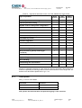
VSEL input signal
VSEL False
VSEL True
Selected Output voltage
V0SET
V1SET
VSEL green LED
LED OFF
LED ON
When channels are switched from V0SET to V1SET or vice versa, the output voltage
drifts from one value to the other at the rate programmed for each channel (Ramp-Up or
Ramp-Down parameter).
4.2.5
ISEL command
Two current limit values can be programmed for each channel: I0SET and I1SET (see
§ 4.4.6 and 4.4.8, p.30). They are selected by the status of the ISEL input signal,
according to the following:
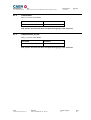
ISEL input signal
ISEL False
ISEL True
4.2.6
Selected Current limit
I0SET
I1SET
ISEL green LED
LED OFF
LED ON
KILL command
The KILL input signal, sent through the relevant connector, allows to switch all the
channels off at the maximum rate available, regardless of the Ramp-Down or other
parameters.
The relevant green LED will be alight as the KILL signal is True.
The KILL command can be also forwarded via software from the Utility Æ Kill menu.
Please refer to § 7.1.15, p.56 for further details.
4.2.7
RESET command
The RESET command (available with system firmware rev. 20031120 and higher and
software rev. 2.00.02 and later)1 allows via the RESET input signal or the RESET pushbutton to reset the system CPU and, optionally, to reset the boards and to turn all the
channels off. The action of the RESET command depends on the duration of the signal
or of the press action (refer to Fig. 4.1):
1
The running firmware and software can be monitored via the Tech Info menu (see § 0).
NPO:
00103/97:2527y.MUTx/14
Filename:
SY2527USERMANUAL_REV14
Number of pages:
86
Page:
24