Download User Manual - Giulio Lighting
Transcript
Wireless Single Fixture DMX Controller User Manual Important Information Please read through these notes and the remaining instructions before installing this device. 1. Refer to local and state codes to ensure compliance when installing this device. Consult an Electrical Inspector if you have any questions. 2. Use only with a listed Class 2 or Limited Power Source external power supply. 3. Be sure to use cables specified for use with DMX systems. 4. Be sure to terminate the DMX chain. 5. Do not exceed a maximum of 30 DMX devices. 6. Do not exceed a maximum of approximately 1000 feet (300 m) for the entire DMX cable run. 7. Make sure that power is disconnected before connecting or disconnecting any DMX devices. 8. Make sure this device and its power supply are located in a dry environment. 9. Be sure to plan the installation before beginning. 1 Model CT-001 The Model CT-001 Wireless Single Fixture DMX Controller is part of the QualColor™ family and controls a white or color-capable DMX light fixture. Integrating a wireless receiver with the sophisticated Giulio Lighting LEDsmarts system, the CT-001 allows full control over a lighting system’s color and intensity. The CT-001 can be operated by any Giulio Lighting controller using the LEDlink wireless interface. Feature Benefit LEDlink digital radio interface Allows easy installation of lighting system components. DMX fixture interface Easy connection to a multitude of different fixtures using tools and cabling most installers already have. Selectable DMX channel formats and assignments Supports a wide variety of fixture types. The CT-001 controller can operate fixtures with different RGB channel assignments, master brightness channels, additional color channels such as white or amber or alternative color encoding schemes such as HSI. LEDsmarts fader Allows any number of fixtures to be operated by one control by distributing the fading operation to the fixture controllers. LEDsmarts automatic programs Allows fixtures to operate independently of the remote controlling device. 2 Introduction Wireless Single Fixture DMX Controller Feature Benefit Configurable Link attributes Allows multiple controllers to coexist and to handle radio interference from external sources. Configurable address Allows sophisticated installations with independently operating fixtures. Configurable calibration Allows tuning of the white light generated by fixtures generating using RGB or RGBA LED configurations. Small size Easily hidden in a convenient location. Device Description The CT-001 is designed to control a DMX light fixture. The fixture may be a single-channel white light fixture or a multi-channel color-capable fixture. The CT-001 controls only intensity when configured to control a single-channel white light fixture. The CT-001 controls intensity and color of a multi-channel color-capable fixture. The CT-001 generates DMX frames consisting of Start Code with a value of 0 followed by 128 8-bit data slots. The 128 data slots consist of 8 unique data bytes repeated 16 times. The CT-001 maps the data to control the light into the 8 unique data bytes. The mapping is configurable and described in the section “DMX Channel Configuration”. The CT-001 can drive up to 30 fixtures. However each fixture must have the same DMX address and use the same mapping of channels to slots. All fixtures will operate identically. 3 CT-001 controls and connectors are shown in the following illustration. 1 2 3 5 4 2 3 6 7 8 1 Side Views Item Description 1 Power Input Jack. Provides power for the CT-001. Connect to a 6 volt DC Class 2 or Limited Power Source. 2 Power Indicator. Green indicator that is lit when the CT-001 is receiving power. 3 CT-001 Configuration. Nine recessed DIP switches used to configure the the CT-001 with the fixture characteristics. The operation of these switches is described in the section “DMX Channel Configuration”. 4 DMX Output Connector. Three-pin XLR female connector that drives the DMX output signals. Pin 1: Ground/Screen Pin 2: Data Pin 3: Data + 5 RF Error Indicator. Red indicator that blinks when the CT-001 detects a missed packet. Excessive blinking of this indicator indicates poor reception by the CT-001. 6 RF Activity Indicator. Green indicator that blinks each time the CT-001 receives a packet over the LEDlink RF interface. 7 Prog Indicator. Red indicator that is lit when the CT-001 is put into Provisioning Mode (the Prog Button is pressed). Remains lit until an external device successfully provisions the CT-001, the Prog Button is pressed a second time or a one hour period expires. 4 
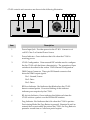
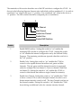
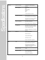
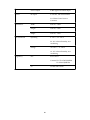
Item Description 8 Prog Button. Recessed button used to put the CT-001 into and out of Provisioning Mode. See section “Provisioning” for a more detailed description of the provisioning process. DMX Channel Configuration There is no standard among fixture manufacturers for the mapping of color channels in a fixture to DMX channels. The CT-001 must be configured to drive the appropriate data in each DMX slot. It can drive data in up to eight DMX slots. The same data is repeated every eight slots for the entire frame. The CT-001 supports fixtures that utilize the following information. • Intensity only: Used for white light fixtures. Supports 256 intensity levels. • RGB: Used for color-capable light fixtures. Supports 256 intensity levels on three color channels (RGB). • RGBA: Used for color-capable light fixtures. Supports 256 intensity levels on four color channels (RGBA or RGBY). • RGBW: Used for color-capable light fixtures. Supports 256 intensity levels on three color channels (RGB) and one white color channel. • HSI: Used for color-capable light fixtures. Supports 256 levels on three color control channels (Hue, Saturation, Intensity). In addition to intensity or color channel information the CT-001 can drive specific values in particular slots for fixtures that need additional control information such as master intensity. The CT-001 is configured in one of two ways: through DIP switches on the side of the unit or via a utility program running on a computer that communicates with the CT-001 via the LEDlink interface. • DIP Switches: Allows configuring operation of a white-only fixture or a RGB colorcapable fixture that maps the color channels sequentially in the order R-G-B. The RGB color-capable fixture may also have a separate master intensity channel. • External Utility Program: Allows full configuration of the CT-001 including RGBA, RGBW or HSI fixtures, arbitrary mapping of color channels and custom control channel values. A description of this configuration method is beyond the scope of this document. Please see the instructions that come with the utility program for the control device that will be used with the CT-001. 5 The remainder of this section describes use of the DIP switches to configure the CT-001. As shown in the following diagram, there are nine individual switches numbered 1-9. A switch is considered “on” when in the up or “1” position. It is considered “off” when in the down or “0” position. The DIP switches should be configured prior to installation. 1 9 1 0 Aux Channel Start Channel Enable Aux Channel Enable Color Enable DMX Switches Switch Description 1 Enable DMX Switches. Setting this switch to “on” enables the remaining DIP switches to configure the CT-001. Setting this switch to “off” enables the internal configuration set by the External Utility Program. The remaining switches are ignored when this switch is in the “off” position. 2 Enable Color. Setting this switch to “on” enables the CT-001 to control a color-capable fixture that utilizes red, green and blue channels. The red, green and blue channels must be in sequential order (for example, Red on channel 1, Green on channel 2 and Blue on channel 3). Setting this switch to “off” enables the CT-001 to control a white fixture that utilizes a single channel for intensity. 3 Enable Aux Channel. Setting this switch to “on” enables the CT-001 to drive a value of 255 on one of the eight channels in order to set a fixture master intensity control to full. The Aux Channel switches set the channel number. Setting this switch to “off” disables the CT-001 from driving an additional value for a master intensity channel. 6 Switch Description 4-6 Start Channel. These three switches select the starting channel for the intensity or color information. They specify the single channel that carries the intensity information when the Enable Color switch is set to “off”. They specify the three consecutive channels carrying red, green and blue information when the Enable Color switch is set to “on”. The channel value ranges from 1 to 8 depending on the switch settings as shown in the following table. Looking at the switches from left to right (Switch 4 - Switch 5 - Switch 6). 000: Start Channel = 1 001: Start Channel = 2 010: Start Channel = 3 011: Start Channel = 4 100: Start Channel = 5 101: Start Channel = 6 110: Start Channel = 7 (not valid for Color fixtures) 111: Start Channel = 8 (not valid for Color fixtures) 7-9 Aux Channel. These three switches select the channel used for the value of 255 when the Enable Aux Channel switch is set to “on”. Looking at the switches from left to right (Switch 7 - Switch 8 Switch 9). 000: Aux Channel = 1 001: Aux Channel = 2 010: Aux Channel = 3 011: Aux Channel = 4 100: Aux Channel = 5 101: Aux Channel = 6 110: Aux Channel = 7 111: Aux Channel = 8 Channels not used to carry intensity/color information or the Aux value of 255 will contain the value of 0. 7 The following examples demonstrate use of the DIP switches for typical fixtures. Example 1 Example 1 shows the configuration for a single-channel white light DMX fixture. The fixture is configured to look at DMX channel 1 for the intensity information. • DMX Switches “on” • Enable Color “off” • Enable Aux Channel “off” • Start Channel = 1 • Aux Channel = don’t care 1 0 Example 1: White fixture Example 2 Example 2 shows the configuration for a three-channel color-capable DMX fixture that utilizes red, green and blue LEDs. The fixture is configured to start at DMX channel 2. The fixture looks for red color information on DMX channel 2, green color information on DMX channel 3 and blue color information on DMX channel 4. • DMX Switches “on” • Enable Color “on” • Enable Aux Channel “off” • Start Channel = 2 • Aux Channel = don’t care 1 0 Example 2: Simple RGB fixture 8 Example 3 Example 3 shows the configuration for a five-channel color-capable DMX fixture that utilizes red, green and blue LEDs. This fixture is configured to start at DMX channel 3. It has the following channel mapping. 1. Red color information 2. Green color information 3. Blue color information 4. Reserved by the fixture manufacturer 5. Master Control. A value of 255 on this channel sets the maximum global intensity. Note that the Aux Channel is enabled and set to 7 so that it will drive the value 255 on the fixture’s Master Control channel. • DMX Switches “on” • Enable Color “on” • Enable Aux Channel “on” • Start Channel = 3 • Aux Channel = 7 1 0 Example 3: RGB fixture with master intensity channel 9 LEDsmarts The CT-001 contains a sophisticated controller called LEDsmarts that manages the LED fixtures locally. The LEDsmarts controller allows installations of LED lighting systems that do not depend on any one central controller to manage all lighting effects. Installations may be controlled by multiple control devices and may even operate independently of any controller. The CT-001 LEDsmarts controller includes the following capabilities. • Color fader: The CT-001 manages transitions from one color and intensity to another one automatically and independently. • Automatic programs: The CT-001 can automatically animate a color-capable fixture with one of two programs. Each program can change the fixture color at one of four speed settings. • Random : The CT-001 fades the fixture(s) smoothly between randomly chosen colors for an ever-changing light show. • Slow : 30 - 180 seconds for each color change. • Medium/Slow : 10 - 60 seconds for each color change. • Medium/Fast : 5 - 30 seconds for each color change. • Fast : 1 - 6 seconds for each color change. • Sequential : The CT-001 fades the fixture(s) smoothly between all the hues in the rainbow. • Slow : 30 minutes for the complete sequence of colors. • Medium/Slow : 10 minutes for the complete sequence of colors. • Medium/Fast : 3 minutes for the complete sequence of colors. • Fast : 15 seconds for the complete sequence of colors. • Color space mapping : The CT-001 automatically controls multiple configurations of LEDs to properly generate colors without requiring any central controllers to have specific knowledge of the fixture. 10 Addressing The CT-001 controller supports Zone/Unit addressing with Group support. • Zone Address: 0-65535. Factory default value of 1. • Unit address: 0-65535. Factory default value of 1. • Four Group Addresses: 0-255. Factory default value of 0 for each group address. Zone addresses are used to associate related fixtures and fixture controllers. For example all fixtures and fixture controllers in one physical location such as a room may be given the same Zone address so that they may be controlled together. Unit addresses are used to control individual lights within a Zone. Each separate fixture or fixture controller is given a unique Unit address allowing it to be controlled alone. Group addresses are used to control groups of related fixtures or fixture controllers within a Zone. All fixtures with the same Group address will respond identically to commands addressing that group. 11 LEDlink Radio Interface A CT-001 and one or more other devices communicate using the proprietary LEDlink radio protocol sharing certain characteristics called a Link. A CT-001 is considered linked to another device when it and the other device share the same Link attributes. These attributes define the Link characteristics. 1. Radio channel : Specifies the common frequency the radio transceiver in the CT-001 and other device(s) are tuned to. 2. Network ID : The Network ID is designed to allow multiple, overlapping installations of fixtures and other controllers to work without interference. The primary use of the Network ID is to prevent an installation of devices in one apartment or home from affecting devices in another apartment or home where the radio signals may overlap. Devices with different Network IDs ignore each other. 3. Device address : Each fixture or fixture controller may be configured with a unique device address. The CT-001 is configured with the device address for the fixture(s) it controls. The factory default configuration for the CT-001 and all LEDlink capable Giulio Lighting control devices contains the same linking attributes allowing a CT-001 fixture controller to immediately work with these devices. Certain conditions may require that one of the Link attributes be changed. Example conditions include the following. 1. The user desires to have multiple CT-001 fixture controllers, each with a different address in order to be operated independently. 2. The user desires to change the Radio channel to avoid radio interference from a device like a microwave oven. 3. The user desires to change the Network ID to avoid interference from a lighting system in another apartment or home. Link attributes are changed using a process called provisioning described in the next section. 12 Provisioning Link attributes and other operating parameters of the CT-001, such as address, are changed by a process called provisioning. During provisioning an external device communicates the new Link attributes to the CT-001 over the LEDlink wireless interface. The external device may be a handheld remote control or some sort of computer interface under the control of software running on a personal computer. The CT-001 is put into a special mode, called the Provisioning or Link mode, by pressing the Prog button and and verifying the Prog Indicator is lit. Typically this is a step described in the User Manual for the device or software being used to provision the CT-001. The CT-001 will remain in Provisioning mode for up to one hour before reverting automatically to normal operation. In Provisioning mode the Link characteristics of LEDlink are set to a known condition so that another device may communicate with it successfully over the LEDlink. Advanced Features The CT-001 supports custom calibration parameters to enhance operation of certain fixture types. 1. White balance calibration : Adjust the amount of red, green, blue and optionally amber used when generating white light for RGB and RGBA fixture types. These calibration parameters allow the user to specify the precise white generated by a fixture that uses separate color components. 2. Amber/Yellow Channel calibration : Specify the precise color of the Amber channel in relation to the green and red channels for fixtures using RGBA or RGBY LED arrays. Use of these calibration parameters is beyond the scope of this document. Please refer to the User Manual for the calibration software available on the Giulio Lighting website. 13 14 Installation Pre-installation It can be helpful to plan an installation prior to starting to physically install components. The following items should be considered when creating the plan. Provisioning Provisioning of the CT-001 is required if any link attributes or other operating parameters must be changed. It may be helpful to provision the CT-001 before installation in order to place the CT-001 and provisioning device in close proximity (although the CT-001 can be provisioned or re-provisioned once installed). It is not necessary to attach any fixture(s) to the CT-001 unless required by the provisioning process. Locate the CT-001 near the provisioning device (within five feet / 2 m). Attach the external power supply to the CT-001 and plug the PSU into an outlet. Press the Prog button to put the CT-001 into Provisioning Mode. Finally follow the procedures described in the User Manual for the provisioning device or software. DMX Fixture Configuration Both the CT-001 and DMX Fixture must have DMX-related attributes configured in order to work together. The CT-001 must be configured to drive the necessary information on the correct slots in the DMX data stream. See the section “DMX Channel Configuration”. The DMX Fixture starting address must be set to match the data transmitted by the CT-001. This starting address is typically a value 1 through 8 although the CT-001 repeats the same information every 8 slots in the DMX data stream. CT-001 and Power Supply Location and Orientation Determine the installation location for the CT-001. The location generally depends on the following factors. • Location of power outlet. The power supply cable length dictates the maximum distance from a power outlet to the CT-001 location. • Access for fixture cabling. The DMX cable connection to the fixture should be routed in an unobtrusive manner. • CT-001 position and orientation for best radio reception. The CT-001 should be located so that there is a clear path for the radio signal from the device that will control it. Examples locations include on the underside or top of a cabinet or in a cove. The CT-001 may be located inside a wood cabinet. However it should never be located inside a metal enclosure or against a metal surface. Note the orientation arrow on the CT-001 label. The indicated side should be mounted closest to nearest wall. 15 The CT-001 will typically work up to 100 feet (30 m) from the controlling device outdoors and 50 feet (15 m) indoors. Actual range may vary substantially based on the position and orientation of the fixture and objects, such as walls, between the CT-001 and the controlling device. The LEDlink radio communication between the CT-001 and the controlling device is very robust. However some other devices, including microwave ovens, cordless phones and Wifi devices, may cause interference. Often changing the radio channel used by the CT-001 can alleviate the interference. See the User Manual for the controlling device or provisioning software for further instructions on changing the channel. Fixture Cabling A DMX cable is routed from the CT-001 to the fixture and from there, in a daisy chain method, to additional fixtures. The maximum length of the DMX cabling from the CT-001 to the final fixture or fixture controller is 1000 feet (300 m) as shown in the following illustration. DMX Fixture DMX Fixture Power External PSU DMX Terminator CT-001 DMX Cable Installation The installation process consists of the following steps. 1. Mount. The CT-001 is designed to be mounted using the supplied screws. 2. Connect fixture using a DMX cable. Be sure to attach a DMX termination device to the fixture DMX Out connector. These steps assume that the fixture is installed according to instructions provided by the fixture manufacturer. 3. Attach power supply. Connect the power supply to the CT-001. 4. Plug power supply into power. Verify the the power indicator is lit. 5. Test installation. Verify correct operation of the installation. The RF Activity LED should blink as commands are transmitted to the CT-001. 16 Troubleshooting Please refer to the following table for help troubleshooting an installation. Problem Power LED does not light Possible Cause No power to outlet. Power Supply not completely plugged into the CT-001. RF indicator does not flash Controlling device is too far from the CT-001. Radio signals are being blocked by materials surrounding the CT-001. The CT-001 and the controlling device are not properly linked (e.g. different radio channel or Network ID). RF Error indicator flashes excessively Controlling device is too far from the CT-001. Radio signals are being blocked by materials surrounding the CT-001. Fixture colors are not as expected The DMX Configuration in the CT-001 does not match the requirements of the DMX fixture. The DMX address of the fixture does not match the channel assignment of the CT-001. 17 18 Specifications Functions Fixture Controller Controls most DMX lighting fixtures. Fixture Support White-only RGB RGBA (RGBY) RGBW HSI Control channel overrides Automatic Functions Pseudo-random color selection with four selections for rate of change. Sequential color selection with four selections for rate of change. Fixture Calibration RGB White calibration RGBA Amber/Yellow calibration Configuration 9-position DIP switch for white or RGB fixtures optionally including master intensity channel. Software configuration for complex fixtures. Interface DMX-512 XLR 3-pin connector 250 kbs data rate 129 byte DMX frames 50 frames/second 8 bytes control data repeated Radio Type Giulio Lighting LEDlink proprietary digital bi-directional protocol. Interoperates with all Giulio Lighting LEDlink capable fixtures and fixture controllers. Modulation Type GFSK Frequency Range 2.4 GHz Instrument, Scientific and Medical band (ISM) 2.402 GHz - 2.480 GHz 19 Power Power Output 0 dBm typical at antenna input DC Input 6 volts DC, 100 mA maximum 2.1x5.5mm Center Positive Connector Dimensions Environmental Width 9.86 cm / 3.880” Length 7.86 cm / 3.095” Height 3.82 cm / 1.505” Operating 0 - 50º C / 32 - 122º F 20 - 90% relative humidity, noncondensing Storage -20 - 60º C / -4 - 140º F 10 - 95% relative humidity, noncondensing Regulatory FCC FCC Class B Contains FCC ID: XO6-DJ2MOD1 IC: 8558A-DJ2MOD1 UL UL2108 and UL8750 20 Warranty Information Manufacturer warrants this product to be free from defects in material and workmanship under normal use and conditions ("manufacturing defect") for a period of one (1) year from date of original purchase (the invoice date). This warranty extends to the original buyer (Purchaser) or end-user customer of Manufacturer authorized reseller, and does not apply to fuses, batteries, equipment attached to product or any product, which, in Manufacturer's opinion, has been misused, altered, neglected or damaged by accident or abnormal conditions of operation or handling. Manufacturer will, at its option, repair or replace the Product, or reimburse Purchaser or end user for the full purchase price. To obtain service, obtain a return authorization (RMA) from the Manufacturer website and then follow the instructions for return of the unit you receive with the RMA. THIS WARRANTY IS PURCHASER’S SOLE AND EXCLUSIVE REMEDY AND IN IS IN LIEU OF ALL OTHER WARRANTIES, EXPRESSED OR IMPLIED, INCLUDING, BUT NOT LIMITED TO, ANY IMPLIED WARRANTY OF MERCHANTABILITY OR FITNESS FOR A PARTICULAR PURPOSE. MANUFACTURER SHALL NOT BE LIABLE FOR ANY SPECIAL, INDIRECT, INCIDENTAL OR CONSEQUENTIAL DAMAGES OR LOSSES, INCLUDING LOSS OF DATA, WHETHER ARISING FROM BREACH OF WARRANTY OR BASED ON CONTRACT, TORT, RELIANCE OR ANY OTHER THEORY. Since some countries and states do not allow limitation of the term of an implied warranty, or exclusion or limitation of incidental or consequential damages, the limitations and exclusions of this warranty may not apply to every buyer. If any provision of this warranty is held invalid or unenforceable by a court of competent jurisdiction, such holding will not affect the validity or enforceability of any other provision of this warranty. 21 This device complies with Part 15 of the FCC Rules. Operation is subject to the following two conditions: (1) This device may not cause harmful interference, and (2) This device must accept any interference received, including interference that may cause undesired operation. This equipment has been tested and found to comply with the limits for Class B Digital Device, pursuant to Part 15 of the FCC Rules. These limits are designed to provide reasonable protection against harmful interference in a residential installation. This equipment generates and can radiate radio frequency energy and, if not installed and used in accordance with the instructions, may cause harmful interference to radio communications. However, there is no guarantee that interference will not occur in a particular installation. If this equipment does cause harmful interference to radio or television reception, which can be determined by turning the equipment off and on, the user is encouraged to try to correct the interference by one or more of the following measures. • Reorient or relocate the receiving antenna • Increase the separation between the equipment and receiver • Connect the equipment into an outlet on a circuit different from that to which the receiver is connected • Consult the dealer or an experienced radio/TV technician for help Any changes or modifications not expressly approved by the party responsible for compliance could void the user’s authority to operate the equipment. 22 FCC Statement INFORMATION TO USER Copyright © 2010 Giulio Lighting All rights reserved Neither the whole nor any part of the information contained in, or the product described in this manual, may be adapted or reproduced in any material or electronic form without the prior consent of the copyright holder. QualColor is a trademark of Giulio Lighting. All other brand or product names are trademarks or registered trademarks of their respective owners. Contact www.giuliolighting.com [email protected] This document and the functionality of the product may be subject to change without 23 notice. Publication 24-00009-01