1
WABCD
~~
SERVICE MANUAL
6078
AUDIO FREQUENCY OVERLAY VS. DC TRACK CIRCUIT
APPLICATION INFORMATION
March, 1978
A-78-200-2130-2
WESTINGHOUSE AIR BRAKE COMPANY
UNION SWITCH & SIGNAL DIVISION
Swissvale Post Office, Pittsburgh, Pa. 15218
An American-Standard Company
~...,
WABCD
TABLE OF CONTENTS
Section
I
AUDIO FREQUENCY OVERLAY VERSUS DC TRACK
CIRCUIT APPLICATION INFORMATION
1.1
1. 2
II
1
1
MAINLINE DC TRACK CIRCUITS
1
2.1
2.2
INTRODUCTION
DC TRACK CIRCUIT PARAMETERS
(Reference Figure 2-1)
1
2.2.1
2.2.2
2.2.3
2.2.4
2.2.5
2.2.6
2
3
5
8
8
8
2.3
2.4
III
PURPOSE OF THIS REPORT
SCOPE
1
Source Voltage
Limiting Resistances "X" and "R"
Level Detection
Relay Resistance
Ballast Resistance
Rail Resistance
BROKEN RAIL DETECTION AND SHUWTING
SENSITIVITY
ADJUSTMENT OF DC TRACK CIRCUITS
2
9
12
AUDIO FREQUENCY OVERLAY (AFO) TRACK CIRCUIT
14
3.1. INTRODUCTION
3.2 AFO TRACK CIRCUIT PARAMETERS
(Reference Figure 3-1)
14
3.2.1
3.2.2
3.2.3
3.2.4
3.3
3.4
3.5
Transmitter Output and Receiver
Sensitivity
Operating Frequency
Ballast Resistance
Rail Impedance
15
15
16
16
16
SHUNTING SENSITIVITY
16
3.3.1
3.3.2
17
Loss of Shunting Sensitivity
Maintaining Shunting
Sensitivity and a Reliable
Track Circuit
ADJUSTMENT OF AFO TRACK CIRCUITS
APPLICATION OF AFO TRACK CIRCUITS
i
17
18
18
SECTION I
AUDIO FREQUENCY OVERLAY ys. DC TRAC,K· CIRCUIT APPLICATION
TNFORMATl:ON
l."1
PURPOSE OF THIS' REPORT
It is suspected that some misunderstanding exists about the
principles of Audio Frequency Overlay (AFO).
Because-of the
· long exi-stanee -and· aoquired -familia-rity wit:!h ·t·he conventional
mainline D.C. Track Circuit it isj?elieved that some maintenance
personnel are attempting to adjus~:·AFO track circuits in the
same manner as the conventional d.1'c. track circuits. Doing
this could create any number"' qf -serious side effects.
r~
It is the purpose of this report tp clear up any misconceptions
by explaining how...ea.ch ci.;r:cuit -operates;· the influencing
.f~ctors and why proper adjustment is required.
·'
l:. 2
SCOPE
This report_ w_il)- f.irst cover the. functio~ an(\ role of D. C.
,, : , Track Ci'rcuit·s, operatlona:l consideration's, a:nd their
· adjustment.
Specifics which will be discussed include Theory
of Operation,, Changes in ballast resistance, shunting
serisit'ivity and ·b:roken tail detectiori'.' .
. ,·
:
Second, a description of operation .. of Aup.io Frequency Overlay
(AFO) its purpose a11d function, theory of operatiop, circuit
parameters, adjustment and mult.iple insta.lli:1.:tiqns will be
presented.
·
'·
·. ·
SECTION II
MAINLIN,E DC T_RACK CIRCUITS
2.1 ·
INTRODUCTION
The purpose of t.he D. C. Track Circuit, invented August 20, 1872,
by Dr. Wiliiam Robinson, is to,·Provid~ Positive 'train
detection in. order to control inainlihe r·ailroad signals.
In
addition to the positive train detection'., 0;:06 ohm shunting
sensit'ivity, d. c. tr.ack :circuits. mu.it provide broken rail
detection, or detect a:'break iri bonding wires around an
insulated joint.
6078, p. 1
WABCD
~
2.2
D.C. TRACK CIRCUIT PARAMETERS (Reference Figure 2-1)
The physical and electrical lengths of the d.c. track circuits
are established by the placement of the two pair of insulated
joints on the rail.
The length of this track circuit is ·
sharply defined to that portion of track between the insulated
joints.
B
x
R
E
Figure 2-1.
Typical Mainline D.C. Track Circuit
TR
Maximum o.c. track circuit length can only be safely arrived
at after considering the factors which are involved:
1.
2.
3.
4.
5.
6.
2.2.1
l;,ource Voltage "E"
Limiting Resistances "X" and "R"
Track Relay's ("TR") Level Detection
Track Relay's ("TR") Resistance
Ballast Resistance "B"
Rail Resistance "Z"
Source Voltage
The first concern is with battery voltage variation; the
minimum voltage at which the circuit must operate properly
at minimum ballast conditions; and the maximum voltage at
which the track relay must release with an 0.06 ohm shunt
or broken rail within the circuit. The smaller the voltage
variation, the longer the track circuit that can be safely
worked for a given minimum ballast. Or the smaller the
voltage variation, the lower the minimum ballast that can be
safely worked. for a given track circuit length.
For years the.railroads have made efforts to improve the
voltage variation associated with track circuit work by good
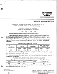
battery maintenance programs. The following tabulation shows
two sets of battery voltage variations, one for track circuit
applications, identified as B, and one for heating and critical
timing problems, identified as A.
6078, p. 2
TYPE OF
BATTERY
B
A
MIN. - MAX.
MIN. - MAX.
Lead Storage
2.0 - 2.3 Volts
1.75 - 2.7 Volts
Nickel Storage
1.2 - 1.6 Volts
1. 1 - 1. 75 Volts
Experience has shown that the railroads have been able to
maintain these closer battery limits with reasonable maintenance programs.
The rewards for these good maintenance
programs are clearly shown on Figures 2-2 and 2-3.
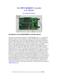
Figure 2-2 shows the maximum D.C. track circuit length possible
for a given minimum ballast, or vice-versa for the high ratio
of release current to working current for the DN-22BH track
relay. Two curves are shown, one for terminal battery voltage
of 2.0 to 2.3 volts and one for terminal battery voltage of
1.75 to 2.7 volts. Note that at 3 ohms per thousand feet
ballast, it is possible to work safely a maximum D.C. track
circuit length of.8,000 feet using Curve A and 12,000 feet
using Curve B. At 5 ohms per thousand feet ballast, this
s~fely increases to a maximum track circuit length of 12,000
f~et using Curve A and 18,000 feet using Curve B.
In other
words, by using the special DN-22BH track relay D.C. track
circuits can be extended approximately 50% farther simply by
maintaining closer battery terminal voltages.
Figure 2-3 is similar to Figure 2-2, except it is for the
standard 4 contact DN-11.
Note that at 3 ohms per thousand feet ballast, it is possible
to have a maximum track circuit length of 1,200 feet using
Curve A and 3,800 feet using Curve B safely. At 5 ohms per
thousand feet ballast, this safely increases to a maximum
track circuit length of 2,000 feet using Curve A and 6,000
feet using Curve B.
In this case D.C. track circuits can be extended to approximately
three times as far simply by maintaining closer battery
terminal voltages. Note that it is much more important that
the closer terminal voltages be maintained for the standard
relay than it is for the special DN-22BH.
2.2.2
Limiting Resistances "X" and "R"
The value of the feed end resistor "X" is determined by:
calculating the minimum amount of resistance in series with
the battery that is required to protect the source voltage
during occupancy.
6078, p. 3
0.5 OHM DN·22BH. Track Relay
Release to Pick-Up-68%
1 Cell Lead Storage
Curve "A"-1.75-2.70 V
Curve "B"-2.0-2.3 V
X=0.5 OHM (Feed End)
0.03 OHM/M' Rail Res.
0.15 OHM Lead Res.
5
~ 4
0::
L:.J
Q.
en
:E
6
3
~
~ 2
u
ci
z.
:E
4
6
8
10
12
14
TRACK CIRCUIT LENGTH IN M'
Figure 2-2.
16
18
Maximum D.C. Track Circuit Length Obtainable With
Poor vs Good Battery Maintenance Using a DN-22BH
Track Relay.
0.5 OHM DN·ll
Release to Pick-Up-45%
1 Cell Lead Storage
Curve "A"-1.75-2.7 V
Curve "B"-2.0-2.3 V
X=0.5 OHM (Feed End)
0.03 OHM/M' Rail Res.
0.15 OHM Lead Res.
5
~
0::
~ 4
en
~
::r:
0
~
3
1
2
3
4
5
6
TRACK CIRCUIT LENGTH IN M'
Figure 2-3.
6078, p. 4
Maximum D.C. Track Circuit Length Obtainable With
Poor vs Good Battery Maintenance Using a DN-11
Track Relay.
w~aca
'V'"A'v'
The following is a list of resistance values that have been
used over the years to protect the various types of batteries
against the short circuit condition of occupancy.
MINIMUM FEED END LIMITING RESISTANCE
TYPE OF BATTERY
STEADY ENERGY CIRCUITS
Lead Storage
0.5
Nickel Storage
0.35 Ohm
Air Cell Primary
0.35 Ohm
Caustic Soda Primary
0.25 Ohm
Ohm
The value at which the adjustable resistor at the relay end "R"
is set is the point where the relay will just deenergize when
a 0.06 ohm shunt is placed across the track (at the relay end}
at a time when ballast resistance is at its minimum.
It is interesting to note that the release time of the standard
DN-11 track relay, with a shunt in the circuit and without any
resistance in series with this relay, is about two seconds.
If we can put a resistor, equal in value to the relay coil
resistance, in series with the standard DN-11 track relay,
we can cut the shunt release time in half or to about one
second. Additional series resistance will, of course, further
reduce the shunt release time.
The release time of the high ratio of release current to
working current for the DN-22BH or PN-150BH track relay with
a train in the circuit and without any resistance in series
with this relay is about seven tenths of a second.
This
quicker release of the high ratio of release current~
working current for the DN-22BH or PN-150BH relay is one of
several very good reasons why this type of relay should be
used as the standard steady energy track relay.
Again, if we
can put a resistor, equal in value to the relay coil resistance,
in series with this type track relay we can cut the shunt
release time in half or to about thirty five hundredths of a
second. Additional series resistance will, of course, further
reduce the shunt release time of this type track rela_y.
2.2.3
Level Detection
Track relays require a certain amount of current for proper
operation and this current level is identified as working
current.
Track relays, in the case of steady energy track
circuits, require the relay current to fall to a certain
level before the relay releases. This current level is
identified as release current. The ratio between the release
current level and the working current level is identified as
level detection.
6078, l?· 5
WRli!ICC
VA,,.'-'
'·
"!
The following tabulation shows how the level detection varies
for several types of track relays.
LEVEL DETECTION
STEADY ENERGY
TYPE RELAY
RATIO
RELEASE CURRENT TO WORKING CURRENT
(2 point)
68%
PN-150BH (2 point)
64%
DN-22
(2 point)
48%
DN-11
(4 point)
45%
DN-11
(6 point)
38%
PN-150B
(6 point)
45%
DN-22BH
Figure 2-4 clearly shows longer track circuits can be used for
a given ballast or track circuits can be operated to a lower
minimum ballast for a given track circuit length with a
higher percentage of level. detection.
The higher% level
detection possible with the DN-22BH or PN-150BH track relaxs
is another good reason why this type relay should be used as
the standard steady energy track relay.
In fact, it is
possible to'use d.c. track circuits with the DN-22BH and PN-150BH
relay track relays up to about the same track lengths as is
possible with coded track circuits, providing foreign current
is not a problem.
As can be seen on Figure 2-4, at 3 ohms per thousand feet
minimum ballast, it is possible to have track circuits or
approximately 3800 feet using a standard type relay and
12,000 feet with the special DN-22BH type relay with 0.06
ohm shunting sensitivity and broken rail protection. At
5 ohms per thousand feet ballast, it is possible to have
track circuits of approximately 6000 feet using the standard
type relay and track circuits are possible using the special
DN-22BH type relay with 0.06 ohm shunting sensitivity and
broken rail protection.
Even when track circuits over 6000 feet in length are not
required, note the minimum allowable ballast required for
circuit operation for the two different type track relays.
The standard track relay will only work to a minimum ballast
resistance of 5 ohms per thousand feet at 6000 feet and still
provide 0.06 ohm shunting sensitivity and broken rail
protection. Whereas, the special DN-22BH type track relay
can safely be used down to approximately 1.25 ohm minimum
ballast for 6000 feet and still provide 0.06 ohm shunting
sensitivity and broken rail protection.
6078, p. 6
Maximum Track Circuit Length
Lead Storage Battery
2.0-2.3 Volts
"A"-DN-(Rel./P.U.=45%)
"B"-DN-22BH (Rel./P.U.=68%)
X=0.5 OHM (Feed End)
0.03 OHM/M' Rail Res.
0.15 OHM Lead Res.
:E
a::
u.J
a..
(/)
:lE
:I:
0
~
t:;
:5
...I
<(
al
u
c:i
:lE
::::>
:lE 1
z
:lE
0
2
4
6
8
10
12
14
TRACK CIRCUIT LENGTH IN M'
16
18
Figure 2-4.
Thus for a given length track circuit, the DN-22BH type track
relay can be used on track having a much lower ballast than
can a standard type relay.
Consequently, ballast maintenance
program is not as critical.
Since much longer track circuits are possible with a.higher
percentage level detection, 100 percent level detection is
desirable.
But it must be safe and it must be practical. The
previously listed level detection figures are only 85% of the
actual manufactured level detection.
It is not practical
to achieve and maintain 100% level detection since such things
as temperature variations, component tolerance, and wear
occur with time in the field.
6078, p. 7
2.2.4
Relay Resistances
The selection of the proper relay resistance also influences
the maximum track circuit lengths possible for agiven ballast
or the minimum allowable ballast for a given track circuit
length as shown below:
LEAD STORAGE BATTERY
DN-22BH
Relay Resistance
2.2.5
Minimum Ballast in ohms
per thousand feet for
6,000 feet circuit.
Maximum Track Circuit
length with broken rail
protection & 0.06 ohm
shunting sensitivity at
3 ohms per thousand feet
ballast.
0.5 ohm
1. 27 ohms/M'
12,000'
1. 0 ohm
1. 5 7 ohms/M'
11,000'
2.0 ohm
1.9
ohms/M'
9,500'
4.0 ohm
2.3
ohms/M'
7,500'
Ballast Resistance
D.C. ballast resistance varies with moisture, type of ballast,
salt content, proximity to the rails, drainage, and tie and
spike conditions. When ballast is frozen, it is nearly
infinity. When ties are good condition and the ballast is
not in contact with the rails a minimum D.C. ballast resistance
of at least 3 ohms per thousand feet could be typical; in
many territories with good drainage and clean ballast, the
minimum D.C. ballast resistance may be 5 or 10 ohms, and in
rare cases unbelievably high. On the other hand, with cracked
and dirt-filled ties, and with dirty ballast in contact with
the rails, the minimum is likely to be 1 ohm.
In salt flat
areas, or where the rails are buried in dirt and cinders,
ballast resistance may fall to less than 0.1 ohm per thousand
feet.
2.2.6
Rail Resistance
The D.C. rail resistance varies with the type of bonding
used as shown below:
(a)
Web type bonding, with 48 inch, 2 #6 Copper, looks like
approximately 0.05 ohm per thousand feet.
(b}
Railhead type bonding looks like approximately 0.03 ohm
per thousand feet.
(c}
Welded rail looks like approximately 0.015 ohm per
thousand feet.
6078, p. 8
These figures for a and bare for 39 foot rails weighing
130 pounds per yard and assumes that no rail joint bars
conduct current and are approximately correct for rails of
other weight than 130 pounds per yard.
2.3
BROKEN RAIL DETECTION AND SHUNTING SENSITIVITY
According to the R.S.& I., track circuits used for signaling
must provide broken rail detection and 0.06 ohm shunting
sensitivity. WABCO interpretates the R.S. & I. requirements
on broken rail protection as that the track relay shall be
in the de-energized position when a rail is broken or removed
except when the break occurs:
a
1.
Within a shunt fouling circuit of
or crossover.
turnout
2.
Between the end of a rail and track circuit
connector.
3.
Within the limits of the rail joint bond
or appliance.
The next consideration must be to insure that a track circuit
will work properly under all the required conditions, and
provide the broken rail protection and 0.06 ohm shunting
sensitivity.required.
To do this, WABCO employs a Master Curve Sheet, Figure 2-5,
for each set of conditions to insure proper working with
the proper limitations.
The Master Curve Sheet uses minimum ballast in ohms per
thousand feet as the base coordinates and R in ohms as the
vertical coordinates. R is defined as the total resistance
at the relay end of the circuit, including the track relay
resistance, track leads and series adjustment resistance
6078, p. 9
Master Sheet
0.5 OHM ON-22BH (0.32A)
1 Cell Lead Storage (2.0 to 2.3V)
5
X=0.5 OHM (Feed End)
0.03 OHM/M' Rail Res.
0.15 OHM Lead Res.
2M'
4
4M'
az
w
>-
j
w
6M'
3
es
8M'
(/)
lOM'
:E
6
2
12M'
14M'
16M'
18M'
~
a::
0
~0_____1______2______3______
4 ______5___
MIN. D.C. BALLAST IN OHMS PER M'
Figure 2-5
At the top of the Master Sheet, the given set of conditions
for which the curve was made up are given.
This particular
curve is for a 0.5 ohm DN-22BH track relay that requires
0.32 for proper working.
The battery is a single cell of
lead storage with 2.0 volt minimum and a 2.3 ampere volt
maximum as previously described in this section under "Source
Voltage". A 0.5 ohm resistance X, including track leads,
is used in series with the battery at the feed end of the
circuit to limit the occupied current level as described under
"Limiting Resistance "X'~ and "R". The D. C. rail resistance
is 0.03 ohm per thousand feet for railhead type bonding as
described under "Rail Resistance". The lead resistance
considered is 0.15 ohm at both ends of the circuit.
If any of the above stated conditions change, then another
Master Sheet must be made up.
A calculation is then made for a given length and a selected
value of minimum ballast. This is to determine the maximum
amount of resistance in ohms at the relay end of the circuit,
R, that can be used in the circuit and still get working
6078, p. 10
current, 0.320A, in the track relay with minimum battery
voltage, 2.0 volts.
The same calculation is repeated for
three or four points of minimum ballast to obtain sufficient
values of R.
This permits plotting of a curve for the specific
length such as two thousand feet, 2M'. The same set of
calculations is repeated for as many lengths as is desirable,
in this case 2M', 4M', 6M', 8M', lOM', 12M', 14M', 16M', and
18 Io
With this curve and the knowledge of minimum expected ballast
and length of circuit, the proper value for R can be read off
that will insure working current in the track relay at that
minimum ballast and at minimum battery cell voltage.
Having considered the factors required to get the working
current into the track relay under the worst expected
conditions, now the limitations must be introduced. The first
limitation, previously covered is rather obvious. That is,
if R includes track relay resistance, track lead resistance
and series adjustment resistance, then R can never be less
than 0.65 ohm (0.5 ohm track relay resistance plus 0.15 ohm
track lead resistance).
So the first limitation drawn is a
straight line across the curve at the 0.65 ohm value for R.
This means that the circuit cannot be adjusted properly for
any part of the curves that extend below the 0.65 ohm line.
The second limitation to consider is the 0.06 ohm shunting
sensitivity. This simply means that an 0.06 ohm train shunt,
anywhere in the confines of the track circuit limits, must
release the·track relay.
The 0.06 ohm shunting sensitivity calculation is a fairly
simple to make since it is made at infinite ballast.
The shunting sensitivity is poorest at the end of the circuit
having the lower value of total resistance connected to the
rails.
Of course, if the circuit is balanced (X = R), then
each end of the circuit will provide the same (poorest)
sensitivity.
Since the value of R isn't normally known to
determine the value two calculations normally made: one with
the 0.06 ohm shunt at the feed end; and one with the 0.06
ohm shunt at the relay end.
With the 0.06 shunt at either end of the circuit and-with
maximum battery voltage, 2.3 volts for lead storage (see
paragraph 2.2.1), and with infinite ballast, the minimum
value of R in ohms is determined that insures less than the
release current, 0.218 ampere, in the track relay.
The
higher value of R in ohms, of the two calculations for each
length, is then cross plotted on the Master Sheet and is
identified on this curve as 0.0688.
This means that the
circuit cannot be adjusted properly to provide 0.06 ohm
shunting sensitivity for any part of the curves that extend
below the 0.06SS curve.
6078 I P• 11
WABCCJ
"V"~
The third limitation to consider is the broken rail protection.
This simply means that a rail break that occurs must release
the track relay.
Unfortunately, there is no easy way to determine what ballast
is most serious when a broken rail occurs in the circuit.
So
a rather laborious calculation is required.
It is obvious
that if the ballast were infinite, there would be no way for
the current to leak around the break.
It is also obvious that
if the ballast were zero, the track circuit would be short
circuited and energy would not be able to be retained in the
track relay.
In performing the calculations to find broken rail protection,
the minimum amount of resistance that can be put in the circuit
must be determined and yet be certain that the track relay
will release.
Once having determined the minimum allowable
resistance in ohms, this must be cross plotted on the Master
Sheet, Figure 2-5 for each length.
This means the circuit cannot be adjusted properly to provide
broken rail protection for any parts of the curves that extend
below the BRP curve.
The limiting curve, either BRP, 0.06SS or 0.65, that requires
the most resistance determines the maximum circuit length for
a specific ballast.
2.4
ADJUSTMENT OF D.C. TRACK CIRCUITS
After this Master Sheet is complete, a Track Circuit Adjustment
Table is prepared as shown on Figure 2-6. On each Track
Circuit Adjustment Table, the type of relay, voltage source,
rail resistance, lead resistance used in the table preparation
is spelled out.
It states adjustments in accordance with this
table, provides 0.06 ohm shunting sensitivity and broken rail
protection.
It should be noted, as it is stated previously, that the
adjustment of a D.C. track circuit is made when ballast
resistance is at the minimum value experienced for that
track circuit.
The reason for this requirement is that to
begin with when adjusted the working to drop away voltage
ratio across the track relay is relatively small due to circuit
design, usually in the order of two to one {2:1) or three to
one {3:1). This value is normally obtained when the ballast
resistance is at its minimum. When ballast resistance goes
higher (when it is dry) there is less ballast leakage
resulting in a higher working voltage at the relay {amount
dependent on track circuit length and other variables).
In
either case,the track circuit continues to operate.
6078, p. 12
T.C. 4879
TRACK CIRCUIT ADJUSTMENT TABLE
~01\-COOEO 0. C. TRACK CIRCUIT COI\TROL
+
ADJUSTMENT TABLE FOR !'.ll~l!'.IL·:,.1
O.C. BALLAST OF 3.0 OHMS/:,.! FT.
Length
Track
Circuit
Rx= 0.35 Ohm
TII
TR = 0. 5 Ohm Style ON-22BH or PN-1 SOBH Mm. \forking 0. 320 Ampere
Eb = I Cell Lead Storage
Rail Resistance 0. 03 Ohm/M ft.
Mm. Resistance to Shunt Track Relay 0. 06 Ohm
Broken Rail Protection
Table based on 0. I 5 ohm total lead resistance (including
track. leads and case wiring) at each end of track circuit.
Note:
Convennonal type track circuits are not normally
recommeoded for lengths over 6000 feet, wiless
there is no possibility of foreign current.
Min.
Rt
Ohms
12000
11000
10000
9000
6000
7000
6000
5000
4000
3000
2000
1000
0.45
0.49
0.51
0. 54
o. 56
0. 59
0.60
0. 63
0.65
0.68
0. 71
o. 74
Min. 0. C.
Ballast
Ohms/M ft.
2. 97
2.68
2.38
2.10
I. 81
1. 55
1. 27
J. 04
o.ao
0. 56
0.33
0.15
. 6000
5000
4000
3000
2000
1000
0.47
0.61
0.81
1.01
J.22
1.48
I. 78
2.13
2.53
3.00
3.56
4.25
.TR Amps.
Ory at
Eb= 2.3V
1.115
1.050
(;. 9h0
0. 920
0.850
0. 790
0. 730
0.6!>5
0.bOO
0.535
0. 475
0.420
ADJUSTMENT TABLE FOR r,.rnm,1L'!\1
0. C. BALLAST OF 5. 0 OHMSr.,I FT.
ADJUSTMENT TABLE FOR MINIMUM 0. C. BALLAST
Length
Track
Circuu
12000
11000
10000
9000
8000
7000
Rt
Ohms
Length
Track
Circuit
TR Amps.
Ory at
Eb=2.3V
12000
11000
10000
9000
8000
7000
6000
5000
4000
3000
2000
1000
1.15
1.15
I. 15
1.15
1.15
1.15
I. 15
I. 15
I. 15
1. 15
I. 15
1. 15
Rt
Ohms
I.JO
1.29
I. 51
I. 75
2.00
2.25
2. 55
2.85
3.20
3.60
4.05
4.55
TR Amps.
Ory at
Eb= 2. 3V
0.845
0.800
o. 760
o. 715
0.670
0.630
0. 585
o. 545
0.510
0.470
0. 435
U.400
I
7/1/65
T.C. 4879
U. S. & S. 01v1s1on
WABCO
Figure 2-6
On each
one for
one for
and one
circuit
D.C. table three sets of data are sho\yll,
3 ohms per thousand feet minimum ballast,
5 ohms per thousand feet minimum ballast,
set that shows the minimum ballast a
length can safely be worked.
6078, p. 13
WABCC
~
However, if the track circuit was adjusted at a value higher
than the minimum ballast resistance value and the ballast
resistance falls, the working voltage at the relay also falls,
due to the ballast leakage increase.
Since the working to
drop-away voltage ratio was small, and with the introductiqn
of more ballast leakage the resulting voltage at the track
relay could fall to (or below) the drop-away value, thereby
causing the relay to deenergize.
The result is an unreliable
track circuit which deenergizes when its ballast resistance
falls, but due only to improper adjustment.
It becomes apparent that to have a reliable D.C. track circuit
it is necessary that it be adjusted when the ballast resistance
is at its minimum and that in order to get broken rail
detection and 0.06 ohm shunting sensitivity that it be
adjusted following the parameters as stated on the appropriate
track circuit table.
The only consideration remaining is when and why does the
ballast resistance reach its minimum value. The actual minimum
ballast resistance condition usually occurs at the beginning
of a rainfall.
The reason for this occurrence is that the rain
combines with the conductive earth salts to form an electrolyte
solution which shunts the track circuit current.
However, as
the rain continues the conductive earth salts are washed away
by the rainfall.
Rainwater being a poor conductor in itself
causes the ballast resistance to increase somewhat above the
value experienced at the beginning of the rainfall.
SECTION III
AUDIO FREQUENCY OVERLAY (AFO) TRACK CIRCUIT
3.1
INTRODUCTION
The purpose of the Audio Frequency Overlay Track Circuit is
to provide a means of vital train detection, 0.06 ohm shunting
sensitivity, and which would be supplemental to those already
present in the railroad mainline signal system. Furthermore,
this circuit does not have need of insulated joints.
It is NOT the intent of AFO type track circuits to provide
the broken rail protection required for signaling purposes,
but that function is the responsibility of the primary track
circuit that the audio frequency overlay (AFO) is suoerimooseo
upon.
6078, p. 14
3.2
TRACK CIRCUIT PARAMETERS (Reference Figure 3-1)
The physical length of the AFO t~ack circuit is established
by the area between the placement of the transmitter's leads
and the receiver's leads. However, since there are no
insulated joints to electrically isolate the circuit, the
electrical length varies with transmitter output and receiver
sensitivity, operating frequency, ballast resistance, and rail
impedance.
re- Ll-Sll:ia.,.l•t-----
L _ _.........,
..........
, IFIIF--
TRANSMITTER
RECEIVER
L
L + L1 + L 2
Figure 3-1.
=
Physical Length
Length
= Electrical
AFO Track Circuit Signal
The electrical length of the track circuit is equal to the
Physical Length distance between transmitter's and receiver's
track leads, (L) plus the amount of spillover (Ll) and(L2)
past the tr~nsmitter and receiver. The total electrical
length of the AFO Track Circuit corresponds to the area
between the point at the receiver end where 0.06 ohm shunt
causes the receiver relay to deenergize and the corresponding
point at the transmitter end.
3.2.1
Transmitter Output and Receiver Sensitivity
When transmitter power is higher, the receiver's sensitivity
is adjusted to a lower level. This results in a decrease in
the lengths of Ll and L2.
Conversely with lower transmitter power, the receiver's
sensitivity must be increased which results in the length of
Ll and L2 to increase.
The main factor in determining the transmitter power required
is the track circuit length to be worked. The limiting
factors of operating frequency, track ballast swing and rail
impedance must all be considered to determine the safe length
of track that can be worked while maintaining 0.06 ohm
shunting sensitivity.
6078, P· 15
3.2.2
Operating Frequency
Longer track circuits can be worked using lower AFO frequencies.
However, the same limiting factors previously mentioned must
be considered to insure shunting sensitivity will be maintained.
Lower frequencies will increase the length of Ll and L2 and
conversely higher frequencies will shorten their length.
3.2.3
Ballast Resistance
Ballast resistance governs the maximum length of a track
circuit. The higher the minimum value experienced, the longer
the track circuit may be used.
Conversely the lower the
minimum value experienced,the shorter the track circuit that
may be used. Again,all other parameters must be considered.
Length of Ll and L2 (amount of spillover) will be longest
when ballast resistance is at its minimum (when wet).
Conversely, these lengths will be at a minimum when ballast
is at it's highest resistance (dry or frozen}.
3.2.4
Rail Impedance
Rail Impedance affects the maximum length obtainable for the
track circuit. Higher rail impedances result in shorter
track circuit lengths that can be worked. ConverselY, lower
rail impedance allow longer distanced to be worked.
Length of Ll and L2 (amount of spillover) will be the longest
when rail impedance is the lowest and shortest when rail
impedance is highest.
Again all other parameters must be considered.
3.3
SHUNTING SENSITIVITY
The application of AFO is greatly simplified since broken
rail detection is furnished by the primary track circuit. The
only remaining concern is that the AFO track circuit be
capable of providing 0.06 ohm shunting sensitivity and that
it sustains relay energization when no train is present.
Both of these conditions must remain satisfied throughout the
entire range of ballast resistance encountered to have a
safe and reliable track circuit.
6078, p. 16
The AFO equipment is designed considering all of the track
circuit parameters discussed previously (3.2 AFO TRACK CIRCUIT
PARAMETERS) and, as can be seen through the description, that
changing one variable can cause several desirable results
while creating a couple not so desirable. All that can be
done is select an area where not too much is sacraficed and
yet reap the best benefits obtainable. AFO design in summary
looks at all the "trade-offs" and places a "design window"
on the area which will provide the best service to the user.
3.3.l
Loss of Shunting Sensitivity
Shunting sensitivity can be lost d~e to:
l.
2.
Excessive Rail Film
Improper Installation Adjustment
a)
Improper Receiver sensitivity setting
b)
Excessive Transmitter Power (Beyond ability to
adjustment of the Sensitivity control with a
0.06 ohm shunt applied).
c)
Combination of (a) and (b).
d)
Performing adjustment when ballast is wet.
3.3.2
Maintaining Shunting Sensativity and a Reliable
Track Circuit
Excessive rail film should not be present where AFO is being
applied. Since AFO is usually applied on mainline there is
usually sufficient rail traffic to offer little chance for
rail film to build up.
Before an installation is made two considerations must be made:
(1) Maximum and Minimum track ballast encountered ( /M') and
(2) track circuit length based on transmitter output power
and frequency.
Since the maximum energy loss will be when the ballast
resistance is at a minimum (when wet), the transmitter's
power and frequency must be sized up to ensure it will work
the length intended. Maximum track circuit length obtainable
is based on the MINIMUM ballast resistance encountered and
the operating frequency (See Table 3-1).
CAUTION
It is electrically possible to keep the relay energized at
lengths greater than that shown. However, it would require the
receiver's sensitivity to be adjusted to a level too high to
provide 0.06 ohm shunting sensitivity. Resetting the
receiver's sensitivity to the proper level would result in
un-reliable relay energization when no train is present.
Therefore, be certain to stay within the guidelines of Table
3-1.
6078, p. 17
WABCD
'V"~
3.4
ADJUSTMENT OF AFO TRACK CIRCUITS
Once the transmitter power and frequency are established
(according to Table 3-1), the equipment is installed, having
the batteries fully charged and several days of dry weather
{or a day when ballast is frozen) proceed as follows:
Connect all AFO units to rails.
Place an 0.06 ohm shunt across the receiver leads at the
case, or across the rails using tight clamps.
Adjust the receiver sensitivity control until the track
relay just releases.
Remove the 0.06 ohm shunt and observe that the relay
picks-up.
Place the shunt at the transmitter's leads - relay should
deenergize.
Remove shunt,relay should pick-up.
1.
2.
3.
4.
5.
6.
Unlike conventional DC track circuits, having only a two to
one (2:1) or three to one (3:1) workina-to drop away voltage
ratio, AFO has a working to drop away ratio in the order of
fourteen to one (14:1) and when adjusted as set forth
by these guidelines, provides sufficient safe overenergization
that it's extremely unlikely for relay deenergization to take
place when it begins to rain as happens, on occasion, with
DC Track Circuits.
3.5
APPLICATION OF AFO TRACK CIRCUITS
A typical AFO installation consists of two AFO Transmitters
and two AFO Receivers of different frequencies connected
as shown in Figure 3-2.
.. ,
AFO
AFO
TRAN,SMITTER
TRANSMITTER
Figure 3-2.
6078, p. 18
t12
Highway Crossing Protection Showing Multiple
Connection Installation.
For multiple crossing- frequencies they should be- staggered as set
forth in Service Manual 5906 (AFO II) or 5906A AFO Repackage.
See the appropriate Service Manual for detailed descriptions
on application and use.
·
1000'
Tl
Figure 3-3.
1000'
T2
1000'
T3
R4
RI
R5
R2
RS
R3
T4
T5
TS
AFO Circuits used for Three or Less Adjacent
Highway Crossings.
6078, p. 19
'~8[
O'I
0
-..J
..
(X)
.
TABLE 3-1.
'O
!'...>
0
MAXIMUM TRACK CIRCUIT LENGTH IN FEET VS. OPERATING FREQUENCY FOR AFO II OVERLAY
(Hz)
OPERATING
FREQUENCY
885
930
1050
1120
1330
1420
1860
2140
2540
2720
3360
3410
4565
5090
6180
6330
LOW POWER UNIT
30% OUTPUT
LOW POWER UNIT
100% OUTPUT
HIGH POWER UNIT
100% OUTPUT
MINIMUM BALLAST
MINIMUM BALLAST
MINIMUM BALLAST
3 OHMS
5 OHMS
3 OHMS
5 OHMS
3 OHMS
5 OHMS
2300
2300
2100
2000
1800
1700
1500
1300
1100
1000
800
800
800
700
600
600
2700
2700
2400
2300
2000
1900
1600
1400
1200
1100
900
900
800
700
600
600
4200
4200
3900
3700
3300
3200
2700
2500
2200
2100
1900
1900
1700
1500
1300
1200
5100
5100
4700
4500
4000
3900
3300
3000
2700
2600
2200
2200
1800
1700
1500
1400
5300
5300
4900
4600
4200
4100
3500
3200
2900
2800
2400
2400
2000
1900
1700
1600
6500
6500
6000
5700
5200
5000
4300
3800
3500
3300
2900
2900
2400
2300
1900
1800
NOTES:
1.
2.
Example - The maximum track circuit length using a 1050Hz low power
transmitter on 100% output setting at 5 ohms minimum ballast
is 4700 ft.
Chart is based on receiving 5 millivolts across a .06 ohm shunt at the
receiver connections.
WABCC
An American-Standard Company
UNION SWITCH & SIGNAL DIVISION
WESTINGHOUSE AIR BRAKE COMPANY
Swissvale, PA 15218