1
SAGA1-L Series
Chapter 4
Operation
4 – 1 Transmitter Configuration
1
9
5
4
5
4
2
3
8
10
SAGA1-L10
7
5
6
5
4
4
SAGA1-L12
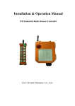
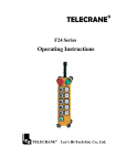
Figure 4-1 Transmitter Configuration
1- Antenna
6- F1 Pushbutton
2- Emergency Stop
7- Start Pushbutton
3- LED Indicator
8- Battery Cover
4- Motion Pushbutton
9- Rotary Key Switch
5- Aux. Pushbutton R1 ~ R4
10-Security Key
6
2
3
1