1
Step Servo Quick Tuner
Software Manual
©Copyright 2015 Applied Motion Products, Inc.
1
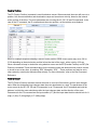
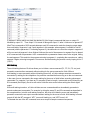
Revision History
Version
Author
1.0
Austin
1.1
Jay
1.2
JK, MC
920-0002 rev j1
Participator
Frank, Jimmy
Date
Changes
2013-7-19
Initial release
2014-12-31
Update new features in Step
Servo Quick Tuner 3.0
2015-1-21
Improved
grammar
punctuation
2
and
2
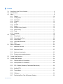
Contents
3.1
3.2
4.1
Step Servo Quick Tuner Overview ................................................................................... 6
User Interface .................................................................................................................. 8
Menu ................................................................................................................................ 9
4.1.1. Project ................................................................................................................ 10
4.1.2. Configuration ...................................................................................................... 11
4.1.3. Q program .......................................................................................................... 11
4.1.4. Connect .............................................................................................................. 12
4.1.5. Ping .................................................................................................................... 12
4.1.6. IP Table .............................................................................................................. 12
4.1.7. Option................................................................................................................. 13
4.1.8. Restore Factory Default ..................................................................................... 16
4.1.9. Alarm History...................................................................................................... 17
4.1.10. Tools ................................................................................................................... 17
4.1.11. Language ........................................................................................................... 19
4.2. Tool Bar .......................................................................................................................... 19
4.2.1. Drive Model ........................................................................................................ 19
4.2.2. Communication Port........................................................................................... 20
4.2.3. Servo Status ....................................................................................................... 20
4.2.4. Upload and Download ........................................................................................ 20
4.2.5. Stop .................................................................................................................... 21
5.1 Motor Configuration ....................................................................................................... 22
5.2
5.3
5.1.1
Maximum Currents ............................................................................................. 23
5.1.2
Maximum Speed ................................................................................................ 23
5.1.3
Maximum Acceleration ....................................................................................... 23
5.1.4
Reverse motor rotating direction ........................................................................ 24
Control Mode Selection ................................................................................................. 24
Control Mode Settings ................................................................................................... 24
5.3.1
Position Mode (I/O Controlled) ........................................................................... 25
5.3.2
Velocity Mode (I/O Controlled) ........................................................................... 28
5.3.3
SCL /Q Mode (Streaming Commands/Stand Alone) .......................................... 29
5.3.4
Modbus/RTU ...................................................................................................... 30
5.3.5
Torque Mode ...................................................................................................... 31
5.3.6
CANopen............................................................................................................ 32
5.3.7
Positioning Error Fault & Electronic Gearing...................................................... 33
920-0002 rev j1
3
5.4
6.1
6.2
7.1
7.2
7.3
8.1
8.2
8.3
8.4
10.1
10.2
10.3
10.4
10.5
11.1
I/O Configuration ............................................................................................................ 34
5.4.1
Digital I/O Configuration ..................................................................................... 34
5.4.2
Analog Input ....................................................................................................... 35
Introduction .................................................................................................................... 35
6.1.1
Velocity Control Loop (V Loop) .......................................................................... 36
6.1.2
Position Control Loop (P Loop) .......................................................................... 37
6.1.3
Notch filter .......................................................................................................... 39
Get Ready for Tuning ..................................................................................................... 39
6.2.1
Position Limit ...................................................................................................... 41
6.2.2
Tuning the Velocity Loop .................................................................................... 42
6.2.3
Tuning the Position loop ..................................................................................... 45
6.2.4
Using Auto Trigger Sampling.............................................................................. 47
Q Programmer Page ...................................................................................................... 49
Current Segment ........................................................................................................... 50
Command Editing .......................................................................................................... 50
Initialize Parameters ...................................................................................................... 52
Point to Point Move ........................................................................................................ 52
Jog ................................................................................................................................. 52
Homing .......................................................................................................................... 53
I/O Monitor ..................................................................................................................... 55
Drive Status Monitor....................................................................................................... 55
Alarm Monitor ................................................................................................................ 56
Drive Parameter Monitor ................................................................................................ 56
Register Monitor ............................................................................................................ 57
Commands .................................................................................................................... 57
11.1.1 Buffered Commands .......................................................................................... 57
11.1.2 Immediate Commands ....................................................................................... 58
11.2 Using Commands .......................................................................................................... 58
11.2.1 Commands in Q drives ....................................................................................... 59
11.2.2 SCL Utility software ............................................................................................ 60
11.3 Command Summary ...................................................................................................... 61
11.3.1 Motion Commands ............................................................................................. 62
11.3.2 Servo Commands .............................................................................................. 63
11.3.3 Configuration Commands .................................................................................. 65
920-0002 rev j1
4
11.3.4 I/O Commands ................................................................................................... 66
11.3.5 Communications Commands ............................................................................. 67
11.3.6 Q Program Commands ...................................................................................... 67
11.3.7 Register Commands .......................................................................................... 68
11.4
12.1
13.1
13.2
13.3
Host Command Reference ............................................................................................ 69
Sample Command Sequences ...................................................................................... 69
CANopen Communication ............................................................................................. 75
Why CANopen ............................................................................................................... 76
CANopen Example Programs ........................................................................................ 76
13.3.1 Profile Position Mode ......................................................................................... 76
13.3.2 Profile Velocity Mode.......................................................................................... 77
13.3.3 Homing Mode ..................................................................................................... 78
13.3.4 Normal Q Mode .................................................................................................. 78
13.3.5 Sync Q Mode ..................................................................................................... 79
13.3.6 PDO Mapping..................................................................................................... 79
13.4
14.1
14.2
14.3
14.4
14.5
14.6
Downloads ..................................................................................................................... 79
Communication Address ................................................................................................ 80
Data Encoding ............................................................................................................... 80
Communication Baud Rate & Protocol .......................................................................... 80
Function Code ............................................................................................................... 81
Modbus/RTU Data Frame .............................................................................................. 81
Application Note: Modbus/RTU from Pro-face HMI ....................................................... 85
920-0002 rev j1
5
3
Introduction
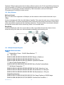
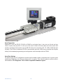
Thank you for purchasing an Applied Motion Products Step Servo product. The Step Servo is an innovative
revolution for the world of step motors; it enhances step motors with servo technology to create a product
with exceptional feature and broad capability. Applied Motion Products’ Step Servo family includes the
SSM, TSM and TXM integrated drive+motor, plus SS and SSAC series stand alone Step Servo drives.
TSM series integrated Step Servo motors
SSM series integrated Step Servo motors with Ethernet
TXM series IP65-rated integrated Step Servo motors for harsh environments
SS series Step Servo drives
SSAC series Step Servo AC drives
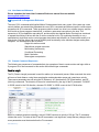
3.1
Step Servo Quick Tuner Overview
Step Servo Quick Tuner is a Windows based software application to configure, perform servo tuning,
program the Q programming, drive testing and evaluation of the Step Servo product. This help explains
how to install Step Servo Quick Tuner and how to configure and tune your Step Servo system. For
information regarding your specific hardware, such as wiring and mounting, please read the hardware
manual that came with the product.
920-0002 rev j1
6
The features of Step Servo Quick Tuner include:
y
Friendly Interface
y
Easy setup within just three steps
y
Drive setup and configuration
y
Servo tuning and sampling
y
Built-in Q programmer
y
Motion testing and monitoring
y
Write and save SCL command scripts
y
Online help integrated
y
Support for all Step Servo products in TSM/SSM/TXM/SS/SSAC series
Remember, if you get in trouble with our motor, drive or software, or if you have any suggestions
about our products and this manual, please call Applied Motion Products Customer Support: (800)
525-1609, or visit us online at www.applied-motion.com.
Software Environment:
Microsoft XP (Service Pack 3), Windows 7/8,Vista with 32bit or 64 bit
Microsoft .Net Framework 2.0
920-0002 rev j1
7
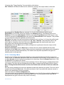
3.2
User Interface
To launch Step Servo Quick Tuner 3 on your Windows PC, click Start → Programs → Applied Motion
Products → Step Servo Quick Tuner 3 → Step Servo Quick Tuner 3.
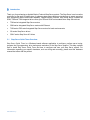
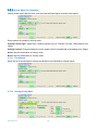
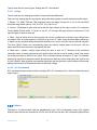
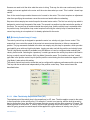
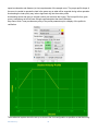
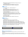
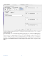
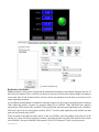
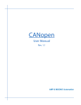
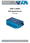
The main screen includes these sections: Menu, Tool Bar, Step 1: Configuration, Step 2: Tuning-Sampling,
Step 3: Q Programmer (Only for –Q/-C Type) and Motion Simulation. See picture below.
Menu
Tool Bar
Command
History Response
Step 1: Configuration
Step 2: Tuning-Sampling
Step 3: Q Programmer
Monitor
Motion Simulation
Menu
The main menu provides some frequently-used operations for configuration and drive control.
Tool Bar
The tool bar is used to set the communication, drive model, Servo status control, Alarm Reset, Upload &
Download.
Step 1: Configuration
This tab provides the drive configuration settings.
Step 2: Tuning-Sampling
This tab provides the tuning and sampling settings, start sample and display sampling curve diagram.
Step 3: Q Programmer
This tab provides the necessary functionality to develop and test Q programs, which are stored in the drive
and can operate stand alone or with the interaction of a host device like a PC, PLC or HMI. It is only for –Q
and –C type.
Motion Simulation
920-0002 rev j1
8
This tab provides motion testing, such as point to point motion, jogging and homing.
SCL Terminal
The SCL Terminal allows you to send SCL commands to the drive. It’s a good way to learn how to use SCL
commands before writing a custom software program to send SCL streaming commands the drive. The
SCL Terminal can also be useful for diagnostics and debugging. For more information about SCL
commands, please refer to the Host Command Reference, available at
http://www.applied-motion.com/products/software/scl-utility
Status Monitor
The Status Monitor can display I/O status, Drive status, Alarms, Parameters and Registers.
4
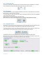
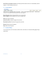
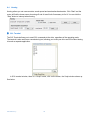
Connecting your Drive to Step Servo Quick Tuner
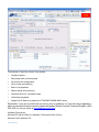
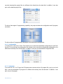
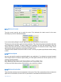
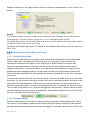
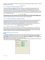
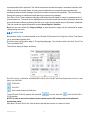
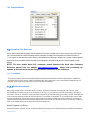
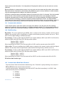
Step Servo Quick Tuner supports two connection types, serial port and Ethernet. For serial port drives, the
connection includes following steps
y Connect the drive to your PC COM port
y Launch Step Servo Quick Tuner
y Switch to RS-232 and select the COM port, see picture below
y Power up the drive
y Step Servo Quick Tuner will recognize the drive model and revision
When launching Step Servo Quick Tuner, the software will search all COM ports available and load then
into the drop down list.
After establishing the connection between the drive and Step Servo Quick Tuner, the software will switch
the baud rate to 115200 bps, no matter what the baud rate was before.
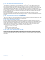
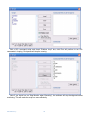
For Ethernet drives, the connection includes following steps
y Connect the drive and PC to your switch or router
y Launch Step Servo Quick Tuner
y Switch to Ethernet and input the drive’s IP address, as pictured below
y Power up the drive
Step Servo Quick Tuner will not detect the drive information automatically, you need to click "Upload"
button in the main screen to get the drive model and revision.
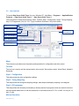
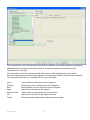
4.1
Menu
920-0002 rev j1
9
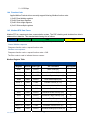
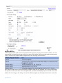
1st Stage Menu
Project
2nd Stage Menu
Hot Key
Function
Open
Ctrl+O
Open the project file (.ssprj format)
Save
Ctrl+S
Save the project file (.ssprj format)
Upload from Drive
Ctrl+U
Upload the project from the drive
Download to Drive
Ctrl+D
Download the project to the drive
Print
Ctrl+P
Print the current project
Exit
Config
Q Program
Exit Step Servo Quick Tuner
Open Config
Ctrl+Shift+O Open configuration file (.ssc format)
Save Config
Ctrl+Shift+S Save configuration file (.ssc format)
Upload from Drive
Ctrl+Shift+U Upload configuration from the drive
Download to Drive
Ctrl+Shift+D Download configuration to the drive
Print
Ctrl+Shift+P Print current configuration
Open Q Program
Open Q program file (.qpr format)
Save Q Program
Save Q program file (.qpr format)
Open Segment
Open Q segment file (.qsg format)
Save Segment
Save Q segment file (.qsg format)
Upload from Drive
Upload Q program from the drive
Download to Drive
Download Q program to the drive
Clear Q Program
Clear Q program
Set Password
Set password to secure Q program
Print Q Program
Print Q program
Connect
Connect or re-connect to the drive
Ping
Ping the Ethernet drive
IP Table
Edit the drive’s table of switch selectable IP addresses
Option
Set Alarm, Regen, Communication and other options
Restore
Restore the drive to the factory default settings
Alarm History
Display drive’s alarm history
Firmware Downloader
English
Upgrade the drive’s firmware
Pilot motion profile based on target distance, velocity,
acceleration/deceleration, etc.
Export CANopen Parameters to a file
Run CANopen Test Tool application (requires
pre-installation)
Set the application language to English
Chinese
Set the application language to Chinese
Move Profile Calculator
Tools
Export CANopen Parameters
CANopen Test Tool
Language
Help
Open the online help
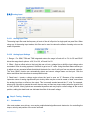
4.1.1. Project
In Project menu, Step Servo Quick Tuner can allow you to upload and download both configurations and a
Q program. Driver configuration and Q programs can be saved as a project file (.ssprj) to your local disk. It
920-0002 rev j1
10
can also download the project files to a different drive directly from the hard disk. In addition, it can also
print out the detailed project files.
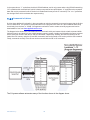
For drives that support Q programming capability, the project includes the configuration and Q program;
see below:
For drives without Q programming, the project is the same as the configuration.
4.1.2. Configuration
In Config menu, Step Servo Quick Tuner allows you to upload and download configurations to and from
the drive. It can also save as configuration file (.sscfg) to your local disk and download configurations to a
different drive directly from the hard disk. In addition, it can print out the detailed configuration files.
4.1.3. Q program
If your drive is a Q, C or IP type, the Q Program menu can save driver’s Q program file (.qpr) to your local
disk. It can also download a Q program to a different drive directly from the hard disk. In addition, it can
print out your Q program.
920-0002 rev j1
11
4.1.4. Connect
Connect Step Servo Quick Tuner to the drive.
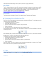
4.1.5. Ping
Ping will verify your network configuration and ensure that the software can communicate with the drive.
Click “Ping” button, the software will check drive's ARM build number and MAC ID.
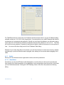
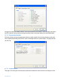
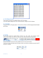
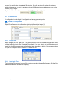
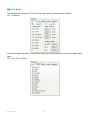
4.1.6. IP Table
IP Table is used to edit the table of switch selectable IP addresses stored in drives with Ethernet ports.
You can input up to 14 IP addresses for the rotary switch positions 1 through E.
Note: After saving the IP address table to the drive, you must power cycle the drive before a new address
can take effect.
920-0002 rev j1
12
For TXM Ethernet drives, which have no IP address selection switch, there is only one IP address setting
available, shown as 10.10.10.10 in the image above. You can set this to any valid IP address that suits the
requirements of your network and application. Should you ever forget this address, you will need a way to
recover the drive. All TXM drives include a permanently fixed recovery address of 10.10.10.10. The TXM
will use this recovery address if it powers up and does not detect a network connection for some period of
time. You can set this time delay period in the IP Address Table dialog.
Example: if you set the time delay for 5 seconds, you can force the drive to revert to the recovery address
by powering it up with the Ethernet cable unplugged, then waiting for five seconds before plugging in the
cable.
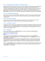
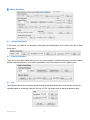
4.1.7. Option
Allows you to set the alarm mask, regeneration resistor, and other parameters
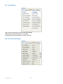
4.1.7.1 Alarm Menu
Sometimes you may see LED alarm codes displayed on your drive that you don’t want to see because
they are part of the normal operation of your application, such as tripping an end of travel limit. In this case
you can inhibit these alarms. Clicking the "LED Flashing" button in the menu will present the following
dialog.
920-0002 rev j1
13
Uncheck the alarms you want to inhibit; if your drive encounters such alarms, it will not display the alarms
by LED. However, the drive will record them and store them in the alarm history for future examination.
4.1.7.2 Regeneration Resistor
SS drives contain an internal regeneration resistor to safely capture kinetic energy returning to the drive
from a rapidly decelerating load so that it does not damage the drive or power supply. This page will help
you set it up.
4.1.7.3 Communication
This page is for setting the communication preferences between the host controller and step servo drive.
920-0002 rev j1
14
Prefix all responses with address character: Instructs the driver to respond to SCL commands with
an address character prefix.
Respond to all commands with Ack or Nack: Respond to all commands with Ack or Nak
Use CheckSum: Use CheckSum during communication
Full Duplex RS-485: Select this for full duplex, 4 wire RS-422/485 networks
4.1.7.4 Other
Velocity, Accel/Decel Unit: Unit settings for velocity, acceleration and deceleration: you can choose
revolutions per second (rps) and rev/sec/sec (rev/s/s) or revolutions per minute (rpm) and rpm/s/s.
920-0002 rev j1
15
When drive is connected: You can choose whether to automatically upload the configuration and/or Q
program from the drive when a drive is first connected to Step Servo Quick Tuner.
4.1.8. Restore Factory Default
The restore button will reset all the parameters on the drive to the default factory settings.
Note: This will erase all the parameters you have changed, so you may need to save them to a file
first.
920-0002 rev j1
16
4.1.9. Alarm History
Applied Motion Products Step Servo drives store a log of previous alarm conditions. Each time there is an
alarm, the drive stores the information of which alarms were triggered at this time. Since a fault may trigger
more than one alarm condition, the drive stores all of them for reference. This information can then be
extracted using Step Servo Quick Tuner to help with drive and system problem solving. The drive stores up
to 8 sets alarm conditions.
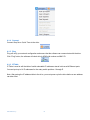
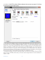
4.1.10. Tools
The Tools menu includes Firmware Downloader, Motion Profile Calculator, Export CANopen Parameters
and CANopen Test Tool, see picture below:
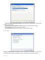
4.1.10.1 Firmware Downloader
Firmware Downloader is used to upgrade the drive firmware. Before upgrading please contact Applied
Motion Products to confirm that you get the proper firmware version to download.
920-0002 rev j1
17
Please follow this sequence to perform a firmware update:
Step 1: Select a firmware file
Step 2: Recycle the drive’s power and wait for 3 seconds
Step 3: Click the “Download” button.
Note: So far Applied Motion Products’ drives do not support multi axis networking firmware updates for
RS-485 field bus. You can only do the firmware updates for each single axis which must be offline from the
network.
4.1.10.2 Move Profile Calculator
Move Profile Calculator provides an excellent tool for the customer to simulate move profiles. The motion
parameters can convert between time and SCL parameters easily via click a button. When the drive is
connected with the software, you can click “Test Profile” to try a move per your inputs.
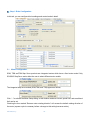
4.1.10.3 Export CANopen Parameters
After tuning is done. Export CANopen Parameters provides a tool to export the tuning parameters such as
KP , KD, VP, VI and etc. and save these parameters to a text file in a specific data format which is easy for
the customer to immigrate to their program. Below is a saved file example.
920-0002 rev j1
18
4.1.10.4 CANopen Test Tool
This provides a quick link to the installed CANopen Test Tool software.
If you have installed CANopen Test Tool, click this will launch “CANopen Test Tool” software.
4.1.11. Language
Language button has 2 language options. You can click one of them to shift the language between English
and Chinese.
4.2. Tool Bar
The Tool Bar includes the Applied Motion Products logo, drive model, drive firmware revision,
communication settings, servo status, plus the alarm reset, upload, download and stop buttons.
4.2.1. Drive Model
The Drive drop-down list shows all of the available step servo drive model numbers.
The Revision window will display a drive's firmware version once the drive is properly connected to the PC
and power is supplied.
920-0002 rev j1
19
4.2.2. Communication Port
Choose the correspondent communication port for the drive before any drive configuration. For RS-485
drives, it allows you to choose the address of the drive to which you wish to connect.
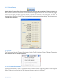
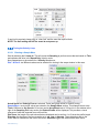
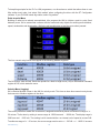
4.2.3. Servo Status
The servo enable switch is used to enable and disable the motor status. It also displays the current status:
when the button is green, the motor is enabled.
“Force EN” allows you enable the motor when a drive is connected to Step Servo Quick Tuner regardless
of the external enable input status.
Alarm reset allows you to reset the alarm, when they occurs.
NOTE: Alarms can only be cleared when the drive’s warning or fault problems are solved.
4.2.4. Upload and Download
Upload lets you copy the set up and tuning parameters from your Step Servo motor into Step Servo Quick
Tuner. This is useful if you want to make changes to a system that has already been tuned.
The Download button is used to copy settings from Step Servo Quick Tuner to your drive. Use this if you
make a change to a drive setting and want to transfer the information back to the drive.
“Upload All from Drive” and “Download All to Drive” will upload or download the whole project.
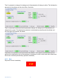
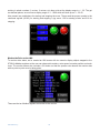
After performing an upload or download, the background of each parameter will change to a green color.
This indicates the parameter in the software and the drive match. See below.
920-0002 rev j1
20
Then if a parameter is changed, the background of that parameter will change to yellow. This indicates the
parameter in the software and the drive differs. See below.
Then if a download is performed after that parameter changes, the background of that parameter will
change back to green. This indicates the parameter is downloaded successfully and the software and
drive are again synchronized. See below.
If the driver is not powered up and connected to the software, or an upload or download has not been
performed, the background color of the parameter is transparent or white, which means the software and
driver have not been synchronized (by upload or download).
4.2.5. Stop
Stop drive’s motion immediately.
920-0002 rev j1
21
5
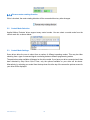
Step 1: Drive Configuration
In this tab, you can configure drive's settings and control mode in detail.
5.1
Motor Configuration
SSM, TSM andTXM Step Servo products are integrated motors which have a fixed motor model. Only
SS/SSAC Step Servo series allow the user to select different motor models.
The integrated step servo models (SSM,TSM, and TXM) appear as follows;
Click “…”to activate the Motor Setup dialog. In this window maximum current, speed limit, and accel/decel
limit can be set.
Checking the box marked “Reverse motor rotating direction” will reverse the default rotating direction of
the motor (a power cycle is necessary before a change to this setting becomes active).
920-0002 rev j1
22
5.1.1
Maximum Currents
The drive current must be set to match the motor. First, determine the rated current for the motor
according to your drive’s hardware manual.
If you are manually setting the current, type the value into the Maximum Current text box.
The step servo drive provides a peak current momentarily. This will provide greater acceleration rates than
would otherwise be possible. To assure reliable motor operation, the drive will automatically ramp the
current down after one second so that the average current does not exceed the motor’s rating. Never
continuously operate a step servo motor above its rated current.
The peak current available varies from model to model, so check your product specifications before setting
a value.
5.1.2
Maximum Speed
Here you can enter the maximum speed allowable in your application. If you attempt to command a speed
that is higher than the maximum speed setting, the final speed achieved will be the speed set in the
maximum speed parameter.
Note: Maximum Speed works with Velocity Mode and Torque Mode Only.
In Pulse Input Mode these values will be limited by your controller’s software.
5.1.3
Maximum Acceleration
This will set the maximum level of acceleration for the motor. Even if the command input tries to demand a
higher level of acceleration, the drive will only accelerate or decelerate at the maximum set level.
920-0002 rev j1
23
5.1.4
Reverse motor rotating direction
If this is checked, the motor rotating direction will be reversed without any other changes.
5.2
Control Mode Selection
Applied Motion Products’ drives support many control modes. You can select a control mode from the
control mode list, as shown below:
5.3
Control Mode Settings
Some drives allow the user to select from a number of different operating modes. This may be either
selecting from a type of command signal or selecting between different programming modes.
The particular modes available will depend on the drive model. If you have your drive connected and it has
been detected by Step Servo Quick Tuner, only the options available on your drive will be shown.
Alternatively, by selecting your model from the drop down list at the top of the screen the options screen for
your drive will be displayed.
920-0002 rev j1
24
5.3.1
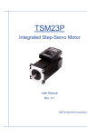
Position Mode (I/O Controlled)
Position mode has two control options: digital input and analog input.
5.3.1.1 Position Control - Digital
Pulse Input Mode is for systems where the position of the motor is determined by a digital input signal in
the form of step pulses combined with another input signal that controls the motor direction. This is also
known as “step direction mode”.
920-0002 rev j1
25
Fig 3.10 Digital Settings in Position Mode
The three modes available are:
Pulse and Direction. Accepts a signal from a motion controller or PLC. With this mode the frequency of
the pulses fed into one input (X1) determines the speed and position, while the direction of rotation is
determined by a signal fed into another input (X2). You can configure whether the X2 signal should be
closed or open to command clockwise motion.
CW and CCW Pulse. The motor will move CW or CCW depending on which input the pulse is fed into.
The drive has two inputs allocated to this feature (X1 and X2); pulses fed into one input will generate CW
motion and pulses fed into the other input will generate CCW motion.
A & B Quadrature. Sometimes called “Slave Mode”. The motor will move according to signals that are fed
to the drive from a master encoder. This encoder can be mounted on a shaft on the machine or it can be
another motor in the system. Using quadrature input mode it is possible for a number of motors to be
“daisy chained” together with the encoder output signal from each drive being fed into the next.
For all the Pulse Input modes you will need to determine a value to enter into the Electronic Gearing box.
An explanation on how to do this is given in the next section.
Direction is CW when
CW direction is determined by the polarity of input X2 which requires to be set in priority.
Smoothing Filter
Setting the electronic gearing (EG) to a low value (typically less than 2000 steps/rev) can result in
rough motion, so set the electronic gearing to a high value if possible. Some PLC’s and motion controllers
have a limited maximum pulse rate, so achieving a high move speed is only possible by setting EG to a
low value. In such cases, smooth motion can still be achieved by using the Step Smoothing Filter.
1) Smaller values give smoother performance.
2) Smoothing filter technology will introduce a time delay; this doesn’t the positioning accuracy at the
end of a move but can cause the actual motion to lag behind the command signal during the
move.
920-0002 rev j1
26
Pulse Input Complete Detection Time
Sets a period of time during which, if the drive doesn’t receive any more pulses, the move is
considered to be complete. This parameter is used for determine whether the motor is in position or not.
See detailed information on the TT command in the Host Command Reference.
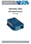
5.3.1.2 Position Control - Analog
Analog position control instructs the step servo motor to position the motor according to an analog input
command. For example, the configuration below would cause the motor to move 8000 counts clockwise
from its current position if the voltage applied to the analog input changes from 0 volts to 5 volts. If the
signal then changed to 2.5 volts, the motor would move 4000 counts CCW.
There is also option for an offset voltage and a dead band. The offset can be used to offset the position in
case the 0 volt signal from your analog command does not represent zero position on your application.
TUNING NOTE: Turning off the KD (differential gain) term will minimize analog noise affects. The higher
the “Position” gain setting the more analog noise will cause dithering.
Fig. 3.9 Analog Settings in Position Mode
920-0002 rev j1
27
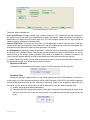
5.3.2
Velocity Mode (I/O Controlled)
Velocity mode means that the drive uses the command input signal to set the motor speed.
Some options are needed in velocity mode.
Velocity Control Type: “Speed Only” (without position error) or “Position over time” (With position error
check)
Velocity Control: Chooses whether the motor speed is fixed is proportional to the analog input voltage
Accel: Sets the acceleration in velocity mode.
Decel: Sets the deceleration in velocity mode.
5.3.2.1 Fixed Speed
Motor will run at a fixed speed, run/stop and direction are controlled by external inputs.
5.3.2.2 Analog Velocity Mode
920-0002 rev j1
28
The box labeled “Speed” enables you to define the speed that the motor will reach with the given analog
settings. For example, if the speed is set to 10 rev/sec the motor will spin in the clockwise (CW) direction at
10 revolutions per second when the analog input signal is 5V. If the analog signal is set to 1 volt, the motor
speed would be 2 rev/sec.
By setting the Speed to the maximum for your application, and not the maximum speed of the motor, you
will achieve higher resolution on the command input and better control.
The speed value can be entered as a negative value. This will allow you to select which direction the motor
will run with a positive command signal voltage.
5.3.3
SCL /Q Mode (Streaming Commands/Stand Alone)
5.3.3.1 SCL
SCL or serial command language was developed by Applied Motion Products to give users a simple way
to control a motor drive via a serial port. This eliminates the need for separate motion controllers to supply
control signals, like pulse & direction, to your drive. It also provides an easy way to interface to a variety of
industrial devices like PLCs, industrial computers, and HMIs, which most often have standard or optional
serial ports for communicating to other devices.
SCL a host controller to send instructions to drives in real time. With SCL, the drives can be operated in
RS-232 or RS-485 mode; the RS-485 option allows you to have multi-axis multi-drop applications with the
drives “daisy chained” on one serial link. When this option is selected you will need to set an address for
each drive that will share the network. Refer to Setting the Address in the next section.
Node ID
In SCL mode with RS-485 communications you will need to set the address for each drive in your system.
Simply select the address character and perform a download; in this way up to 32 drives can be connected
together on a single serial link.
For some drive models, you can only select drive’s RS-485 address by the switch directly on the drive.
920-0002 rev j1
29
Transmit delay
This sets up the transmit delay for communications between host controller and the drive. This is highly
necessary for 2 wire configurations for RS-485 communication. The host must disable its transmitter
before it can receive data. This must be done quickly before a drive begins to answer a query.
Baud rate
At power up, a drive will send a “power-up packet” to see if it can find the Step Servo Quick Tuner software.
If, after one second, it does not receive a response from Step Servo Quick Tuner, the drive will enter SCL
or Q operation, depending on the PM setting. The drive will set the baud rate according to the value stored
in the Baud Rate NV parameter. Changing this parameter will take effect on the next drive power up.
Data format
This sets the numeric format for SCL immediate queries like IV and IT. You can choose hexadecimal and
decimal. See the Host Command Reference for details.
Auto Execute Q Program at Power Up
If this is checked, the drive will execute stored Q program from segment 1 automatically at power up.
5.3.3.2 Q Program
The Q language is a superset of the SCL streaming language that allows a user to compose programs
that can be stored and executed in the drive. These programs are saved in a drive’s non-volatile memory,
and the drive can run these programs stand-alone, or with a connection to a host. The drive can be
configured to automatically run the Q program at power up, or to wait for instructions from a host, which
can start and stop the program on demand. Q programs can also be started and stopped using fieldbus
commands in CANopen and EtherNet/IP models.
By combining the ability to run a sophisticated, single-axis motion control program stand-alone with the
ability to communicate serially to a host device, Q drives offer a high level of flexibility and functionality to
the machine designer and system integrator, with available commands for motion control, multi-tasking,
conditional processing, math calculations, and data register manipulation.
Q programming is described in detail in the Host Command Reference.
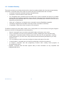
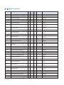
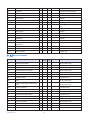
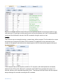
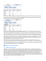
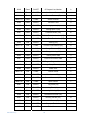
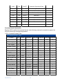
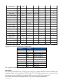
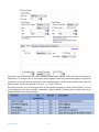
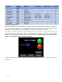
5.3.4
Modbus/RTU
Node ID
In a networked system, each drive requires a unique address. Only the drive with the matching address
will respond to the host command. In a Modbus network, address “0” is the broadcast address. It cannot
920-0002 rev j1
30
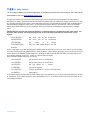
be used as an individual drive’s address. Modbus RTU drives can drive addresses from 1 to 32. Applied
Motion step servo drives use the same address for SCL and Modbus, but in a slightly different way for
each. The relationship between the Modbus Node ID and the SCL address character is shown in the table
below.
Node ID
1
2
3
4
5
6
7
SCL Address
1
2
3
4
5
6
7
8
8
Node ID
9
10
11
12
13
14
15
16
SCL Address
9
:
;
<
=
>
?
@
Node ID
17
18
19
20
21
22
23
24
SCL Address
!
"
#
$
%
&
'
(
Node ID
25
26
27
28
29
30
31
32
SCL Address
)
*
+
,
-
.
/
0
Auto Execute Q Program at Power Up
If this is checked, the drive will execute stored Q program from segment 1 automatically at power up.
32 bit word order
Big-endian: The most significant byte (MSB) value is stored at the memory location with the lowest
address; the next byte value in significance is stored at the following memory location and so on. This is
akin to left-to-right reading in hexadecimal order.
Little-endian: The most significant byte (MSB) value is stored at the memory location with the highest
address; the next byte value in significance is stored at the following memory location and so on. This is
akin to right-to-left reading in hexadecimal order.
When setting up a Modbus network, be sure to check the word order of your host device, then set your
step servo drive to match. If the word order (also called endianness) does not match, the motor will move
much farther than you command.
5.3.5
Torque Mode
When the drive is set up for Torque mode, it allows you to define the current that will be delivered and thus
the torque generated by the motor and the direction it will rotate. In this mode the speed that the motor
runs at will depend on the load applied to the motor.
WARNING - If the motor is not connected to the load or has no load applied, downloading this mode while
there is a command signal present may cause the motor to accelerate to a high speed.
920-0002 rev j1
31
Torque mode has two control types, Analog and SCL Commanded.
5.3.5.1 Analog
Torque mode has two analog input options: single ended and differential.
There are four settings that are required for getting the analog inputs to control the desired mode output:
1. Range – For SSM, TSM and TXM integrated motors the range is fixed at 0 to 5V; for SS and SSAC
drives the range has 4 options: ±10V, 0 to 10V, ±5V, and 0 to 5V.
2. Current – Establishes a gain value that scales the input voltage to the output current. For example in
Current Mode (Torque mode), if “Current” is set to 5, a 5 volt input will apply 5 amps to the motor. A 2 volt
input will apply 2 amps to the motor.
3. Offset – Sets an offset value to the input that can null out a voltage bias or shift the input voltage value
as needed. Often in analog systems it is difficult to get a true “0” value. Using the offset feature allows you
to adjust out any unwanted offsets that disturb the desire for a true 0 volt input from an external controller.
The “Auto Offset” function can automatically detect and correct voltage biases on the input. Click the
button and follow the instruction to accomplish this task.
4. Dead band – Inserts a voltage region where the input is seen as “0”. Because of the sometimes
imprecise nature of analog signals and input circuitry there may be a need to create a “dead” zone where
the analog input has no effect on the output. This is normally needed around the “0” input. For example,
when using a joystick to operate the motor the user may not want any torque output when the Joystick is at
its “Null” position. Most joysticks are somewhat imprecise and may produce a small voltage at the neutral,
adding a dead band can eliminate the effect of the small voltage.
5.3.5.2 SCL Commanded
SCL commanded torque mode works by accepting SCL GC commands from a host to control the motor’s
output torque.
5.3.6
CANopen
CANopen is a communication field bus standardized by the CAN in Automation Group (CiA). Applied
Motion Products drives are compliant to CiA 301 and CiA 402 and use the CAN 2.0B passive physical layer.
920-0002 rev j1
32
Detailed information on the Applied Motion Products CANopen implementation can be found on our
website.
Node ID
In a CANopen network, each drive needs to have a unique node ID. CANopen node ID addresses are
represented as 7 bit binary numbers, ranging from 1 to 127 (hexadecimal 0x01 to 0x7F).
For Applied Motion drives, the low 4 bits of the node ID are set by the switch on the drive, and the upper 3
bits must to be set by Step Servo Quick Tuner.
TXM drives do not have rotary switch. The Node ID and CANopen Baud rate are all set by Step Servo
Quick Tuner.
5.3.7
Positioning Error Fault & Electronic Gearing
5.3.7.1 Positioning Error Fault
Positioning error is the difference, in encoder counts, between the actual position and the commanded
position of the motor. A small amount of positioning error is a normal part of a servo system. But
sometimes the unexpected can happen. A wire might break, a sensor could fail or the motor may
encounter a physical obstruction. You might even one day forget to set up and tune a drive before
installing it into a system. In all of these cases, you’ll want to know that something is wrong as soon as
possible and without damaging anything. For this reason, the step servo drives include a position error
fault limit. Anytime the position error (as reported by the encoder) exceeds this limit, the drive cuts power
to the motor.
You can set the fault limit to as little as 10 encoder counts, or as much as 32000. When you’re first tuning
the system, you should set this value high or select “Not Used” so that the drive doesn’t shut down as you
experiment with tuning parameters. Once the drive is properly tuned and you know how much error to
expect during normal operation, you can set an appropriate fault limit. For example: set Step Servo Quick
Tuner’s scope to plot position error. Execute some aggressive sample moves, using the maximum speed
and acceleration that you plan to use in your application. If the maximum position error is, say, 50 counts,
then you could safely set the fault limit at 100.
5.3.7.2 Electronic Gearing
Electronic Gearing allows you to adjust the way that the drive responds to incoming step pulses. This is
very useful if you are replacing a step motor drive with a step servo system, because you can make the
drive have the same number of steps/revolution as the stepper. For example, you may have an 8000 count
920-0002 rev j1
33
encoder, but want the drive to operate at 200 steps/rev, like a full step drive. Or perhaps the system is
working in degrees, so you want to operate the drive at 36,000 steps/rev so that there is an even number
of steps (100) per degree.
Simply enter the number of steps/rev you want in the “Electronic Gearing” text box.
5.4
I/O Configuration
I/O configuration includes digital I/O configuration and analog input configuration.
5.4.1
Digital I/O Configuration
Digital I/O configuration is to configure the digital inputs(X) and digital outputs(Y).
5.4.1.1 FI Input filter
Applies a digital filter to a given input. The digital input must be at the same level for the time period
specified before the input state is updated. For example, if the time value is set to 100 the input must
remain high for 100 processor cycles before the input state is consider to be high. One processor cycle is
200 µsec for a Step Servo drive. A value of “0” disables the filter.
5.4.1.2 Input Noise Filter
The Input Noise Filter acts as a low-pass filter, rejecting noise above the specified frequency. Set the Pulse
Width, the software will calculate the frequency.
920-0002 rev j1
34
5.4.2
Analog Input
5.4.2.1 Analog Input Filter
The analog input filter sets the frequency in hertz of the roll off point of a single pole low pass filter. When
using any of the analog Input modes, this filter can be used to reduce the affects of analog noise on the
mode of operation.
5.4.2.2 Analog Input Settings
1. Range – For SSM, TSM and TXM integrated motors the range is fixed at 0 to 5V; for SS and SSAC
drives the range has 4 options: ±10V, 0 to 10V, ±5V and 0 to 5V.
2. Offset – Sets an offset value to the input that can null out a voltage bias or shift the input voltage value
as needed. Often in analog systems it is difficult to get a true “0” value. Using the offset feature allows you
to adjust out any unwanted offsets that disturb the desire for a true 0 volt input from an external controller.
The “Auto Offset” function can automatically detect and correct voltage biases on the input. Click the
button and follow the instructions to accomplish this task.
3. Dead band – Inserts a voltage region where the input is seen as “0”. Because of the sometimes
imprecise nature of analog signals and input circuitry there may be a need to create a “dead” zone where
the analog input has no effect on the output. This is normally needed around the “0” volts. For example,
when using a joystick to operate the motor the user may not want any torque output when the joystick is at
its “Null” position. Most joysticks are somewhat imprecise and may output a small voltage at the neutral
position; adding the dead band can eliminate the effect of the small voltage.
6
6.1
Step 2: Tuning - Sampling
Introduction
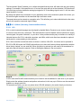
Like most modern servo drives, ours employ sophisticated algorithms and electronics for controlling the
torque, velocity and position of the motor and load.
920-0002 rev j1
35
Sensors are used to tell the drive what the motor is doing. That way, the drive can continuously alter the
voltage and current applied to the motor until the motor does what you want. This is called “closed loop
control.”
One of the control loops controls the amount of current in the motor. This circuit requires no adjustment
other than specifying the maximum current the motor can handle without overheating.
Step servo drives employ two control loops for the actual motor motion. The first is a velocity loop which is
designed to control only the speed of the motor. The second is a position loop that controls the position of
the motor. The current loop is contained inside the velocity loop, and the velocity loop is contained within
the position loop. Good position loop control requires first tuning the velocity loop. As mentioned above,
current loop tuning is not required as it is already optimized for the motor.
6.1.1
Velocity Control Loop (V Loop)
The velocity control loop is designed to operate the motor in a velocity-only type of servo control. This
means that it can control the speed of the motor but cannot cause the motor to follow a commanded
position. The jog commands available in the drive can employ only this loop for operation, which provides
good stability even with very high inertia loads. Jogging can also use both the position and velocity loops.
The JM (Jog Mode) command is available to set this feature or it can be configured when selecting the
velocity control mode. Selecting the “speed only” control type causes the velocity loop alone to be used in
the jog or velocity control functions. JM2 (Jog Mode 2) does the same. The “position over time” control
type adds in the position control loop for precise position control during the move and when stopped. JM1
(Jog Mode 1) also selects this setting.
The velocity control loop has four terms that can be configured for optimum performance with a given load.
This loop can be set and tuned independently of the position control loop. These control terms are
described below.
6.1.1.1 Gain: The Velocity Proportional Term (VP)
The simplest part of the velocity loop is the proportional, or VP, term. The drive applies current to the motor
in direct proportion to the velocity error. For example, if a motor is not moving, and the shaft is turned by
hand or some other force, the drive will increase the motor current until the motor returns to “0” speed. The
faster the motor is moved from “0” velocity, the more the opposing torque will increase. The VP term (also
called VP gain) governs how much torque will be applied for a given amount of velocity error (Vn). In
920-0002 rev j1
36
general, more load inertia or load friction, requires more torque and therefore a higher VP gain. The torque
provided by the VP term is:
T = VP * Vn
6.1.1.2 IntegGain: The Velocity Integral Term (VI)
In the previous example, applying the VP term alone will not result in perfect velocity control. If one
ounce-inch of torque were applied to the motor, it would move at a slower speed. The VP term will
increase the motor torque until it is producing as much torque as the force attempting to move it. The
motor may slow down or even stop moving but there will still be error. The VI term adds up all the error the
velocity calculation has reported and produces a torque that is added to the torque command from the VP
term. The equation for this is:
T = VP * Vn + VIΣ(V)
In the example, the VP term allowed the motor to reach equilibrium at a speed where the applied torque
equaled the torque of the VP term. Thus, the error was not zero. But the VI term continues adding up the
error and increasing the torque until the motor returns to the true target position.
6.1.1.3 FF Gain: Acceleration Feed-forward Term (KK)
Larger loads typically generate larger load Inertia. These larger inertias can be more easily controlled by
anticipating the system’s torque need. The acceleration feed-forward term does this by adding an
acceleration value to the torque command. The acceleration value is derived from the trajectory
calculation during the acceleration and deceleration phase. As can be seen in the equation below this
increased torque command is added with the VP and VI torque command values:
T = KK * A + VP * Vn + VIΣ(V)
6.1.1.4 PID Filter: Torque Command Filter Term (KC)
This fi nal term in the Velocity control loop can be considered an over-all fi lter term. In fact this term is
always used even when the drive has been placed in the Torque Control Mode where only the current
control loop is active. The fi lter is a very simple single-pole low pass fi lter that is used to limit the high
frequency response of the velocity and therefore the position control loops.
6.1.2
Position Control Loop (P Loop)
The Position Control Loop is designed to provide the typical positioning control for a servo system. All
positioning type operations use this loop including when operating in the Pulse & Direction Position
Control Mode. The Position loop can also be used in the Velocity Control Mode when the Position over
time control type option is selection or the Jog Mode is JM=1.
The Position Control Loop has three terms that can be configured for optimum performance with the given
load. These control terms are described below.
920-0002 rev j1
37
6.1.2.1 Gain: The Position Proportional Term (KP)
The simplest part of the position loop is the proportional, or KP, term. The drive applies current to the
motor in direct proportion to the position error. For example, if a motor is not moving, and the shaft is
turned by hand or some other force, the drive will increase the motor current until the motor returns to the
commanded target position (rest position). The farther the motor is moved from its target position, the
more the torque will increase. The KP term (also called KP gain) governs how much torque will be applied
for a given amount of error (Un). In general, more load inertia or load friction, requires more torque and
therefore a higher KP gain.
Because of the topology of the control loops, the position control loop output is actually a velocity
command that indirectly affects the torque command to the motor. The velocity command provided by the
P term is:
V = KP * Un
6.1.2.2 The Position Integral Term (KI) - Not Implemented
There is no KI term as it is not required because of the velocity loop which contains an Integrator term. Any
position error will taken up and corrected for in the velocity loop.
6.1.2.3 D Gain: The Derivative Term (KD)
A motor run with a pure PI controller would overreact to small errors, creating even larger errors and
becoming unstable. By predicting what a motor will do ahead of time, the large errors and instability can be
avoided. The derivative term determines this by analyzing the rate of change of the position error and
including that in the torque calculation. For example, if the motor has a position error, but the rate of
change of the error is decreasing, torque is lowered. The formula used here is:
V = KP * Un + KD * (Un – (Un-1))
where:
Un is the error in encoder counts
Un-1 is the error of the previous sample
6.1.2.4 D Filter: Torque Command Filter Term (KE)
A derivative control term can be rather noisy and even though it is effective in damping the positioning
control, it can cause objectionable audible or observable noise to the system. The filter is a very simple
single-pole low pass filter that is used to limit this high frequency noise and make the system quieter and
more stable.
920-0002 rev j1
38
6.1.3
Notch filter
For additional filtering, an over-all notch filter is added to the current command signal. This filter is similar
to the PID Filter in that it is active even when the drive is used in torque control mode. Notch filters are
typically used to filter at a particular frequency when there is a resonant component in the mechanical
system that may oscillate at that frequency. Couplers between the motor and the load can commonly do
this which may result in a control problem. When gains are increased to improve performance the system
may resonate in an uncontrollable manner. Then notch filter allows gain reduction at only the problematic
resonant frequency, allowing the over-all gain to be set higher for better system control.
The notch filter has two parameters that are described below. The notch filter can only be configured
though the Step Servo Quick Tuner interface where the Step Servo Quick Tuner software calculates the
filter constants used by the drive.
6.1.3.1 Frequency: Notch Filter Center Frequency
This defines the center frequency - the frequency where the most gain reduction occurs. For now,
finding the center frequency is a bit of a guessing game and different frequencies can be tried until
the system resonance is eliminated.
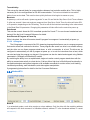
6.1.3.2 Bandwidth: Notch Filter Frequency Bandwidth
This defines the frequency span where the signal is reduced by at least 3dB. For example if the center
frequency is set to 400Hz and the bandwidth to 200 the signal will be reduced by 3dB starting at 300 Hz. It
will have the greatest reduction at 400Hz, and then will be greater than 3dB above 500Hz. When setting
the notch filter a chart is displayed that provides an indication of the
filtering that will be accomplished.
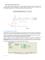
6.2 Get Ready for Tuning
Before testing a servo-system a few more parameters need to be entered. These include the max
920-0002 rev j1
39
speed, acceleration and distance (or time) requirements of the sample move. The proper profile shape of
the move is needed to operate the load in the same way as what will be expected during online operation.
Accelerating the load quickly may induce significant ring into the motion profile.
Accelerating slower and going to a higher velocity can minimize the ringing. The best profile for a given
move is sometimes arrived at more through experimentation than hard calculation.
Step Servo Quick Tuner provides easy entry of the profile parameters plus a display of the profile for
verification.
The mechanical system should be set up as close to the final configuration as possible so that the tuning
920-0002 rev j1
40
represents what will be expected. The critical components include the coupler, mechanical interface, and
similar frictional and inertial loads. As tuning can sometimes be an uncontrolled process where the
mechanical system can be damaged, care must be taken to minimize this possibility. This could include
having limit sensors or mechanical stops that help to prevent such damage.
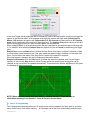
Step Servo Quick Tuner contains a sampling oscilloscope that will display of variety of measurements of
an executed move. Two plots can be displayed at one time and contain the real-time information about the
move performance. Before performing the test move, make sure the desired move information is selected.
This can include the typical information such as Actual Speed or Position
Error but also can include the Supply Voltage so that the power supply can be monitored for proper
voltage during the move.
6.2.1
Position Limit
Before servo tuning, it is recommended to set CW and CCW position limit. Step Servo Quick Tuner allows
you to set software position limit.
Switch the main configuration page to Tuning-Sampling page. You will see 4 tabs: Limit; Auto Tune; Fine
Tune, and Notch Filter.
The soft limit setting is shown as follows;
Set JOG velocity, acceleration and deceleration values, then use the arrow and flag buttons to move to and
define your soft limits:
:CCW JOG
:CW JOG
:Set Current Position As Soft Limit
To set CW and CCW limit, please click and hold
to move, and click
to set limit for CW or
CCW direction.
NOTE: In order to prevent accidents, please choose small JOG velocity and acceleration and
deceleration value.
After both CW and CCW is set, click set limit to activate the function. As shown in below:
920-0002 rev j1
41
If new limit is required, please click on “clear limit” and the reset the required limits.
NOTE: The limit setting will NOT be saved at next power up.
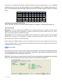
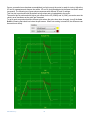
6.2.2
Tuning the Velocity Loop
6.2.2.1 Entering a Sample Move
Start by selecting the V Loop tab. This will cause the Sampling to perform moves that are based on Time
and operates the drive in the Speed Only Velocity mode.
Now parameters may be entered for a Velocity based move.
Plot 1 & Plot 2: two different values can be selected for viewing in the scope window, in this case
Actual Speed and Velocity Error are selected. These are typical values for Velocity tuning.
Sample Move: move profile values are entered in the Sample Move section. This example sets a move
Time of 300ms at a Jog Speed of 10 rev/sec and an Accel/Decel rate of 100 rev/s/s. In the window to the
right of the Sampling data entry section the Desired Profile will be displayed. This provides a visual
reference of what the expected move will look like.
Plot Zoom: the length of the plot values that are displayed can be set from 1 to 5 times the profile length.
Direction: the direction of the move can be set to cw, ccw or alternate. These directions refer to the
motor shaft as viewed from the front of the motor. Alternate toggles the direction after each move.
920-0002 rev j1
42
Start with a known direction before switching to toggle.
Sample Once: after the Start button is clicked, a single move is performed, the motor stops, and the
results will be displayed.
Sample Continuously: after the Start button is clicked, the move will be repeated and the results
displayed until the Stop button is clicked. During continuous sampling the tuning gains can be changed at
any time and will be updated automatically. This enables more dynamic adjustment of the gains for
speeding up the tuning process.
6.2.2.2 Performing a Move
Once the move settings are correct the mechanism to be moved shold also be checked to ensure it is
ready to move. It is especially important to make sure the direction is set correctly. In some cases it is wise
to select alternate to avoid running the mechanism into a hard stop. Select the Sample Once button.
Click the Start button and observe the results.
If problems occurred during the move an Alarm indicating a Fault or Warning may be displayed and need
to be cleared. The drive may be left disabled until the Alarm is cleared and the Enable button is clicked.
Note: Clicking the Alarm Reset button and then the Enable button will clear a fault and enable the
drive.
Now the motion parameters will need to be adjusted to achieve the desired move profile. The move can be
repeated by clicking the Start button. If the drive continues to fault it is possible the maximum current or
position error parameters are being exceeded. These can be set in the Drive Configuration tab.
The current setting can be checked by selecting Current in one of the Plot lists and clicking Start again to
see what current is being required of the drive during a move. The current profile of the move will be
displayed and may give a clue as to why a fault is occurring.
6.2.2.3 Adjusting Tuning Parameters
The two primary parameters for a Timed move are the Proportional (VP) & Integral (VI) gain parameters
of the velocity loop.
Starting with these two terms is a good way to begin tuning as they are the minimum required terms in
Velocity Loop tuning. The FF Gain is not required but adds to the tuning, this will be discussed later.
Note 1: The Servo On button in the Menu bar of the Step Servo Quick Tuner window under the label
Servo will disable the motor should a serious problem occur.
Note 2: The Gain values can be changed at any time during the tuning process. When the STEP SERVO
Quick Tuner software detects a change in the value it will automatically download the new value. The
Download button in the upper right of the window does not need to be clicked.
920-0002 rev j1
43
Once a successful move has been accomplished (no fault occurs) the motor is ready for tuning. Adjust the
VP and VI parameters and observe the results. VP and VI shold be adjusted at the same time and in small
increments. The following two figures shows responses with different VP and VI settings.
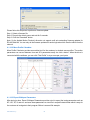
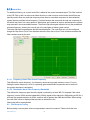
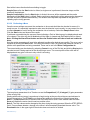
This first plot is performed with the default tuning values and no load added to the motor.
The second plot is performed with higher gain values for the VP (25000) and VI (3000), as can be seen the
velocity error decreases as the gains are increased.
To get a good comparison between different plots where the gains have been changed, turn off the Auto
Scale by clearing that check box below the plot screen. When auto scaling is turned off, the difference can
be seen more clearly.
920-0002 rev j1
44
6.2.2.4 Adding in the FF Gain (KK) parameter
The Acceleration Feed Forward (KK) applies more current to the motor to help compensate for high inertia
in the system. In a servo system more current is typically required during the acceleration and deceleration
phases of the move profile.
A reduction in the Velocity Error peak values should then be seen. As seen in this plot with the KK set to
3000 the peaks in the Velocity error have been reduced. With loads that have greater inertia this can
provide a significant improvement.
NOTE: The FF Term (KK) is not available when operating in the Pulse & Direction Control
Mode. Setting this value will have no effect.
If the Velocity Error goes too positive during acceleration, the adjustment was too large and the value
should be adjusted in smaller amounts until there is as near to zero error as possible. The
Rescale button next to the Auto Scale may be clicked at any time to re-scale the plot on the new
Velocity Error value.
6.2.2.5 Filter parameter
Step Servo has a control loop filter for special situations where the motor may resonate or may have
significant audible noise. This filter is designed as a low pass type for the control loop output.
When a system is subject to mechanical resonance, this low pass filter can be set below the natural
frequency of the system so that the control loop output does not excite the resonance.
With a large inertial load, the gain parameters, especially the VP and VI terms, may need to be set high to
get a good response. The filter may then need to be decreased in value (lower frequency) to prevent
ringing or oscillation. The default of 15000 works well in many cases but can be increased or decreased
with little risk.
6.2.2.6 Verify the Drive Current
The amount of drive current can be verified at any time during the tuning process to make sure the current
supplied to the motor is not being limited by the drive. If too much current is being required changes may
be made to the move profile. Select Current in one of the Plot selection lists and repeat the move, from
this the current can be evaluated.
6.2.2.7 Finishing up
If the Step Servo will only be operated in a Velocity Control Mode with a Speed only Control Type, the
tuning is complete. The Position Loop (P Loop) does not need to be tuned as it is not used. After verifying
the drive current, the Notch Filter may be the only setting still needing adjusting. See section on “Setting
the Notch Filter”.
If the Step Servo will be operated in a Position Control Mode, proceed to section ”Tuning the
Position Loop” below.
See Section below on “Using Auto Trigger Sampling” for tuning the Step Servo while using an external
Pulse & Direction controller.
6.2.3
Tuning the Position loop
6.2.3.1 Entering a Sample Move
Select the P Loop tab . This will cause the Sampling to do moves that are based on distance and
operates the drive in the Point to Point Positioning mode.
Now the parameters for a Position based move can be entered. There is one consideration that must be
addressed here. If the Step Servo is being operated in the Position Control Mode with a Pulse &
Direction Digital Signal Type setting and being commanded by, for example, an external Pulse and
Direction controller, the Auto Trigger option may be used to capture and plot the move. See Section on
920-0002 rev j1
45
“Using the Auto Trigger Sampling” for more details on this feature.
Plot 1 & Plot 2: two different values can be selected for viewing in the scope window, in this case
Actual Speed and Position Error are selected. For Position tuning these are typical values.
Sample Move: move profile values are entered in the Sampling section. This example sets a move
Distance of 3.00 revs at a Max Speed of 20,000 rev/sec and an Accel/Decel rate of 200 rev/s/s. In the
window to the right of the Sampling data entry section the Desired Profile will be displayed. This provides
a visual reference of what the expected move will look like.
Plot Zoom: the length of the plot values that are displayed can be set from 1 to 5 times the profile length.
Direction: the direction of the move can be set to cw, ccw or alternate. These directions refer to the
motor shaft as viewed from the front of the motor. Alternate toggles the direction after each move.
Start with a known direction before switching to toggle.
Sample Once: after the Start button is clicked, a single move is performed, the motor stops, and the
results will be displayed.
Sample Continuously: after the Start button is clicked, the move will be repeated and the results
displayed until the Stop button is clicked. During continuous sampling the tuning gains can be changed at
any time and will be updated automatically. This enables more dynamic adjustment of the gains for
speeding up the tuning process.
6.2.3.2 Performing a Move
Once the move settings are correct the mechanism to be moved shold also be checked to ensure it is
ready to move. It is especially important to make sure the direction is set correctly. In some cases it is wise
to select alternate to avoid running the mechanism into a hard stop. Select the Sample Once button. Click
the Start button and observe the results.
If problems occurred during the move an Alarm indicating a Fault or Warning may be displayed and need
to be cleared. The drive may be left disabled until the Alarm is cleared and the Enable button is clicked.
Note: Clicking the Alarm Reset button and then the Enable button will clear a fault and enable the
drive.
Now the motion parameters will need to be adjusted to achieve the desired move profile. The move can be
repeated by clicking the Start button. If the drive continues to fault it is possible the maximum current or
position error parameters are being exceeded.
These can be set in the Drive Configuration tab.
The current setting can be checked by selecting Current in one of the Plot lists and clicking Start again to
see what current is being required of the drive during a move. The current profile of the move will be
displayed and may give a clue as to why a fault is occurring.
920-0002 rev j1
46
6.2.3.3 Adjusting the Gain (KP) and Deri. Gain (KD) parameters
Adjust the KP and KD parameters and observe the results. Increasing the KP may improve the positioning
performance, but it may also cause the system to be more unstable. To counter this the KD can be
increased. The KD parameter is important: too little gain will cause the system to oscillate; too much gain
may cause the system to squeal from a high frequency oscillation. If a very springy coupler is used
between the motor and load, the KD parameter may need to be reduced until the system is stable or the
Notch Filter may need to be used to reduce the system gain at the sensitive frequency where it oscillates.
6.2.3.4 The Deri Filter (KE) parameter
With a large inertial load, the KP and KD gain parameters may need to be set high to get good response.
The filter may then need to be decreased in value (lower frequency) to prevent ringing or decrease the
derivative noise.
6.2.3.5 Filter parameter (again)
Sometimes it may also be necessary to adjust the output filter when gain values increase. The filter
frequency may then need to be decreased in value to prevent ringing or oscillation.
6.2.3.6 Verify the Drive Current
The amount of drive current can be verified at any time during the tuning process to make sure the current
supplied to the motor is not being limited by the drive. If too much current is being required changes may
be made to the move profile. Select Current in one of the Plot selection lists and repeat the move, from
this the current can be evaluated.
6.2.3.7 Finishing up
After verifying the drive current, the Notch Filter may be the only setting still needing adjusting.
See section on “Setting the Notch Filter”.
6.2.4
Using Auto Trigger Sampling
In cases where an external controller is used to perform move profiles, such as in the Position
Control Mode using Pulse & Direction input, the Auto Trigger will allow the Sampling to collect data
and display the move profile.
This sampling technique is different in that it is not triggered by the start of a move profile as the drive
cannot know when the move is actually started (remember the controller is external). Instead the Auto
Trigger waits for a predefined set of conditions to tell it when to start collecting the move profile data.
When using Auto Trigger, the primary effort is to select the conditions that will trigger the sampling. Begin
by selecting the desired trigger value in the Plot 1 list. This selection is what is monitored by the Auto
Trigger, Plot 2 is not monitored.
920-0002 rev j1
47
In the Auto Trigger tab the displayed text will indicate the value to be used and the conditions to trigger the
capture of the selected value. In the example to the right, the capture will begin when Actual Speed is
Above 1.000 rev/sec, the capture will Capture data for 0.300 seconds and there will be a 10% Capture
delay from the beginning of the capture to the trigger point. The Capture delay allows viewing of the data
prior to the trigger point so that a more complete profile can be observed.
When changing Plot 1 to other selections notice that the conditions for the capture trigger will change with
it. For example, when selecting Position Error the capture will look at Counts for determining the trigger
point.
Sample Once: when the Start button is clicked the Step Servo drive begins continuous collection of data.
It will constantly check the data to see if the value meets the capture trigger conditions. At the same time
Quick Tuner monitors the status of the Step Servo to detect if the capture is complete.
When the capture is complete the data is displayed in the profile window.
Sample Continuously: when the Start button is clicked the capture is repeated each time the trigger
condition is met until the Stop button is clicked. During continuous sampling the tuning gains can be
changed at any time and will be updated automatically. This allows more dynamic adjustment of the gains
for speeding up the tuning process
NOTE: When adjusting control loop gain values remember that the FF Term (KK) has no
effect when operating in the Position – Pulse & Direction Control Mode.
7
Step 3: Q Programming
The Q programming language allows you to create motion control programs and store them in your step
servo drive’s built-in, non-volatile memory. A Q program can be set to run automatically when the drive
920-0002 rev j1
48
powers up, or to wait for a “go” command from a host PC, PLC, HMI or other device. Q programs are
useful in creating standalone motion control devices and for creating customized, distributed control nodes
for a RS-485, Modbus, EtherNet/IP and CANopen networks.
Q programs have access to all of the drive’s control modes and move types. Other capabilities include
multitasking, looping, conditional processing, subroutines, fault handling, math calculations and data
register manipulation.
A single Q program can have 12 individual segments, each segment can have maximum 62 lines of
command.
7.1
Q Programmer Page
The Q programmer page is used for creating Q programs to be stored on and executed by your step servo
drive. At the top of the page are nine command buttons.
Open Q program: Open Q program file from your computer disk
Save Q program: Save Q program file to your computer disk
Print: Print current Q program
Upload from Drive: Upload Q program from the drive.
Download to Drive: Download current Q program to the drive.
Clear Q Program: Clear current Q program.
Execute: Execute current Q program.
Stop: Stop the current running Q program
Set Password: Set Q program password. This locks your Q program to prevent unauthorized persons
from uploading it from your drive. If you forget your password, you can enter the default password “1234”
to unlock it, but it will also erase the stored Q program.
920-0002 rev j1
49
Auto Execute Q program at power up: checking this box instructs the drive to automatically execute
segment 1 of the Q program at power up.
7.2
Current Segment
There are up to 12 segments within a Q program. Click on each segment’s tab to edit it.
its own set of command buttons that pertain only to that segment.
Each tab has
Open Q segment: Open Q segment file from your computer disk
Save Q segment: Save Q segment file from your computer disk
Print: Print current Q segment
Upload from Drive: Upload Q segment from the drive.
Download from Drive: Download Q segment from the drive.
Execute: Execute current Q segment.
Stop: Stop current Q segment.
7.3
Command Editing
If you click any box in the Cmd column, and then click on the button, the Command editing page will pop
up as follows:
920-0002 rev j1
50
The Command list is on the left hand side of the window. In addition, you can also search for commands by
alphabetical order by opening the list above the tree, or type the command name directly into the
“command” box on the right.
If the command is found, the command details will be shown on the right hand side of the window.
Command values can be entered via the parameter 1 and parameter 2 boxes if needed by the command.
The Comment field allows you to describe this line of your Q program.
Insert:
Previous:
Next:
Apply:
Apply and Next:
Ok:
Cancel:
920-0002 rev j1
Insert a blank line within the current Q segment.
Moving up by one line within the current Q segment.
Moving down by one line within the current Q segment.
Apply current command to the segment
Apply current command and move to the next line.
Apply current command to the segment and quit.
Quit the command editing window without save the change.
51
8
8.1
Motion Simulation
Initialize Parameters
In this frame you’ll want to set the speed, acceleration and deceleration to be used by the Point to Point
Move frame.
8.2
Point to Point Move
The Point to Point Move frame allows you to set a move distance, and then command a move to relative
position, absolute position or to a sensor connected to one of the step servo drive’s digital inputs.
8.3
Jog
The Jog frame allows you set the jog speed and jog acceleration/deceleration, then move the motor at a
constant speed on command. Hold the CW Jog or CCW Jog button down to start and release to stop.
920-0002 rev j1
52
8.4
Homing
Homing allows you set a sensor state, search speed and acceleration/deceleration. Click "Start" and the
motor will find the home sensor, bouncing off end of travel limits if necessary to find it. You can click the
"Stop" button to interrupt when homing.
9
SCL Terminal
The SCL Terminal allows you to send SCL commands to the drive, regardless of the operating mode.
The terminal is also useful as a commissioning tool, allowing you to test your drive and SCL without having
to launch a separate application.
In SCL terminal window, there is a “Script” button, click on the button, the Script window shows up.
See below.
920-0002 rev j1
53
Edit a SCL command script and check “Endless Loop” box, click Run will perform to run SCL
commands in looping. Click pause will stop the running.
Note if you check box on “Stop Monitor when Executing”, the software will stop background status
monitoring. This will make the script run more efficiently.
920-0002 rev j1
54
10 Status Monitor
The Status Monitor can display I/O status, Drive status, Alarms, Parameters and Registers.
10.1 I/O Monitor
It shows the Digital Input status, measures the analog input value and be able to control the digital output
status.
10.2 Drive Status Monitor
920-0002 rev j1
55
10.3 Alarm Monitor
There are two categories of alarm, faults and warnings.
A faults alarm will be indicated in red color flag.
A warning alarm will be indicated in yellow color flag.
10.4 Drive Parameter Monitor
920-0002 rev j1
56
10.5 Register Monitor
11 Appendix A: SCL Reference
SCL or Serial Command Language, was developed to give users a simple way to control a motor drive via a serial
port. This eliminates the need for separate motion controllers to supply control signals, like Pulse & Direction or
+/-10V signals, to step and servo motor drives. It also provides an easy way to interface to a variety of other industrial
devices like PLCs and HMIs, which most often have standard or optional serial ports for communicating to other
devices.
NOTE: For more details about SCL command, please download the latest Host Command
Reference manual from our website www.applied-motion.com. Check back periodically for
updates as this document may be changed without notification to the customers.
11.1 Commands
There are two types of host commands available: buffered and immediate. Buffered commands are loaded into
and executed out of the drive’s volatile command buffer, also known as the queue. Immediate commands are not
buffered: when received by the drive, they are executed immediately.
11.1.1 Buffered Commands
After being loaded into the command buffer of a drive, buffered commands are executed one at a time. (See
“Multi-tasking in Q Drives” below for an exception to this rule). If you send two buffered commands to the drive in
succession, like an FL (Feed to Length) command followed by an SS (Send String) command, the SS command sits
in the command buffer and waits to execute until the FL command is completed. The command buffer can be filled
up with commands for sequential execution without the host controller needing to wait for a specific command to
execute before sending the next command. Special buffer commands, like PS (Pause) and CT (Continue), enable the
buffer to be loaded and to pause execution until the desired time.
Stored Programs in Q Drives
Stored Q Programs, created with the Q Programmer application software, are created by using only buffered commands.
920-0002 rev j1
57
Multi-tasking in Q Drives
Multi-tasking allows for an exception to the “one at a time” rule of buffered commands. The multi-tasking feature of a
Q drive allows you to initiate a move command (FL, FP, CJ, FS, etc.) and proceed to execute other commands
without waiting for the move command to finish.
11.1.2 Immediate Commands
Immediate commands are executed right away, running in parallel with a buffered command if necessary. For
example, this allows you to check the remaining space in the buffer using the BS (Buffer Status) command, or the
immediate status of digital inputs using the IS (Input Status) command, while the drive is processing other
commands. Immediate commands are designed to access the drive at any time.
Applied Motion Products recommends waiting for an appropriate Ack/Nack response from the drive before sending
subsequent commands. This adds limited overhead but ensures that the drive has received and executed the
current command, preventing many common communication errors. If the Ack/Nack functionality cannot be
used in the application for any reason, the user should allow a 10ms delay between commands to allow the drive
sufficient time to receive and act on the last command sent.
This approach allows a host controller to get information from the drive at a high rate, most often for checking drive
status or motor position.
11.2 Using Commands
The basic structure of a command packet from the host to the drive is always a text string followed by a carriage
return (no line feed required). The text string is always composed of the command itself, followed by any parameters
used by the command. The carriage return denotes the end of transmission to the drive. Here is the basic syntax.
YXXAB<cr>
In the syntax above, “Y” symbolizes the drive’s RS-485 address, and is only required when using RS485 networking. “XX” symbolizes the command itself, which is always composed of two capital letters. “A” symbolizes
the first of two possible parameters, and “B” symbolizes the second. Parameters 1 and 2 vary in length, can be letters
or numbers, and are often optional. The “<cr>” symbolizes the carriage return which terminates the command string.
How the carriage return is generated in your application will depend on your host software.
Once a drive receives the <cr> it will determine whether or not it understood the preceding characters as a valid
command. If it did understand the command the drive will either execute or buffer the command. If Ack/ Nack is
turned on (see PR command), the drive will also send an Acknowledge character (Ack) back to the host. The Ack for
an executed command is % (percent sign), and for a buffered command is * (asterisk).
It is always recommended that the user program wait for an ACK/NACK character before subsequent commands are
sent. If the ACK/NACK functionality cannot be used in the application, a 10ms delay is recommended between
non-motion commands.
If the drive did not understand the command it will do nothing. If Ack/Nack is turned on a Nack will be sent, which is
signified by a ? (question mark). The Nack is usually accompanied by a numerical code that indicates a particular
error. To see a list of these errors see the PR command details in the Appendix of the Host Command Reference.
Responses from the drive will be sent with a similar syntax to the associated SCL command.
YXX=A<cr>
920-0002 rev j1
58
In the syntax above, “Y” symbolizes the drive’s RS-485 address, and is only present when using RS-485 networking.
“XX” symbolizes the command itself, which is always composed of two capital letters. “A” symbolizes the requested
data, and may be presented in either Decimal or Hexadecimal format (see the IF command). The “<cr>” symbolizes
the carriage return which terminates the response string.
11.2.1 Commands in Q drives
Q drives have additional functionality in that commands can also be composed into a stored program that the Q drive
can run stand-alone. The syntax for commands stored in a Q program is the same as if the commands were being
sent directly from the host, or “XXAB”. Q Programmer software is used to create stored Q programs and can be
downloaded for free from www.applied-motion.com.
The diagram below shows how commands sent from the host’s serial port interact with the volatile command buffer
(AKA the Queue), and the drive’s non-volatile program memory storage. Loading and Uploading the Queue contents
via the serial port are done with the QL and QU commands, respectively. Similarly, the Queue’s contents can be
loaded from NV memory using the QL and QX commands, and can be saved to NV memory with the QS command.
Finally, commands currently in the Queue can be executed with the QE or QX command.
The Q Programmer software automates many of the functions shown in the diagram above.
920-0002 rev j1
59
11.2.2 SCL Utility software
The SCL Utility software is an excellent application for familiarizing yourself with host commands. SCL Utility can be
downloaded for free from www.applied-motion.com
To send commands to your drive from SCL Utility simply type a command in the Command Line and press the
ENTER key to send it. (Remember that all commands are capital letters so pressing the Caps Lock key first is a good
tip). Pressing the ENTER key while in SCL Utility does two things: it terminates the command with a carriage return
and automatically sends the entire string. Try the example sequence below. In this example, note that <ENTER>
means press the ENTER key on your keyboard, which is the same as terminating the command with a carriage
return.
IMPORTANT: We recommend practicing with SCL commands with no load attached to the motor shaft. You
want the motor shaft to spin freely during startup to avoid damaging mechanical components in your
system.
AC25<ENTER>
Set
accel
rate
to
25
rev/sec/sec.
DE25<ENTER>
Set
decel
rate
to
25
rev/sec/sec
VE5<ENTER>
Set
FL20000<ENTER>
Move the motor 20000 steps in the CW
velocity
to
5
rev/sec
direction.
If your motor didn’t move after sending the FL20000 check the LEDs on your drive to see if there is an error present.
If so send the AR command (AR<ENTER>) to clear the alarm. If after clearing the alarm you see a solid green LED it
means the drive is disabled. Enable the drive by sending the ME command (ME<ENTER>) and verify that the you
see a steady, flashing green LED. Then try the above sequence again.
Here is another sample sequence you can try.
JA10<ENTER>
Set jog accel rate to 10 rev/sec/sec
JL10<ENTER>
Set jog decel rate to 10 rev/sec/sec
JS1<ENTER>
Set
CJ<ENTER>
Commence jogging
CS-1<ENTER>
Change jog speed to 1 rev/sec in CCW direction
SJ<ENTER>
Stop jogging
jog
speed
to
1
rev/sec
In the above sequence notice that the motor ramps to the new speed set by CS. This ramp is affected by the JA and
JL commands. Try the same sequence above with different JA, JL, JS, and CS values to see how the motion of the
motor shaft is affected.
920-0002 rev j1
60
11.3 Command Summary
This section contains a set of tables that list all of the Host Commands available with drives that accept streaming
commands. In each table there are a number of columns that give information about each command.
•
“Command” shows the command’s two-letter Command Code.
•
“Description” shows the name of each command.
•
“NV” designates which commands are Non-volatile: that is, which commands are saved in non-volatile
memory when the SA (Save) command is sent to the drive. Note that certain commands (PA, PB, PC, PI,
and PM) save their parameter data to non-volatile memory immediately upon execution, and need not be
followed by an SA command.
•
“Write only” or “Read only” is checked when a command is not both Read/Write compatible.
•
“Immediate” designates an immediate command (all other commands are buffered).
•
“Compatibility” shows which drives use each of the commands.
The different categories for these tables - Motion, Servo, Configuration, I/O, Communications, Q Program, Register are set up to aid you in finding particular commands quickly.
•
“Motion” commands have to do with the actual shaft rotation of the step or servo motor.
•
“Servo” commands cover servo tuning parameters, enabling / disabling the motor, and filter setup.
•
“Configuration” commands pertain to setting up the drive and motor for your application, including
tuning parameters for your servo drive, step resolution and anti-resonance parameters for your step
motor drive, etc.
•
“I/O” commands are used to control and configure the inputs and outputs of the drive.
•
“Communications” commands have to do with the configuration of the drive’s serial ports.
•
“Q Program” commands deal with programming functions when creating stored programs for
Q-programmable drives.
• “Register” commands deal with data registers. Many of these commands are only compatible with
Q-programmable drives.
920-0002 rev j1
61
11.3.1 Motion Commands
Command
Description
NV
AC
Accel Rate
•
All drives
AM
Accel Max
•
All drives
CJ
Commence Jogging
DC
Distance for FC, FM, FO, FY
•
All drives
DE
Decel Rate
•
All drives
DI
Distance or Position
•
All drives
ED
Encoder Direction
•
Servos and steppers with encoder
feedback
EF
Encoder Function
•
Servos and steppers with encoder
feedback
EG
Electronic Gearing
•
All drives
EH
Extended Homing
EI
Input Noise Filter
EP
Encoder Position
FC
Feed to Length with Speed Change
•
All drives
FD
Feed to Double Sensor
•
All drives
FE
Follow Encoder
•
All drives
FH
Find Home
•
All Step Servo drives and M2 Servo
drives
FL
Feed to Length
•
All drives
FM
Feed to Sensor with Mask Dist
•
All drives
FO
Feed to Length & Set Output
•
All drives
FP
Feed to Position
•
All drives
FS
Feed to Sensor
•
All drives
FY
Feed to Sensor with Safety Dist
•
All drives
HA
Homing Acceleration
•
All Step Servo drives and M2 Servo
drives
HC
Hard Stop Current
•
All Step Servo drives
HL
Homing Deceleration
•
All Step Servo drives and M2 Servo
drives
HO
Homing Offset
•
All Step Servo drives and M2 Servo
drives
HS
Hard Stop Homing
HV
Homing Velocity
HW
Hand Wheel
JA
Jog Accel/Decel rate
•
All drives
JC
Velocity mode second speed
•
All drives
JD
Jog Disable
•
All drives
JE
Jog Enable
•
All drives
920-0002 rev j1
write
only
•
•
•
read Immediate Compatibility
only
All drives
All Step Servo drives and M2 Servo
drives
All drives
Servos and steppers with encoder
feedback
•
All Step Servo drives
All Step Servo drives and M2 Servo
drives
•
•
62
All drives
JL
Jog Decel rate
•
All drives
JM
Jog Mode
•
Al drives (see JM command)
JS
Jog Speed
•
All drives
MD
Motor Disable
•
All drives
ME
Motor Enable
•
All drives
MR
Microstep Resolution
•
Stepper drives only
PA
Power-up Accel Current
•
STM stepper drives only
SD
Set Direction
•
STM stepper drives with Flex I/O
only
SH
Seek Home
•
SJ
Stop Jogging
•
SM
Stop the Move
•
SP
Set Absolute Position
ST
Stop Motion
All drives
•
All drives
Q drives only
All drives
•
•
All drives
VC
Velocity for Speed Change (FC)
•
All drives
VE
Velocity Setting (For Feed
Commands)
•
All drives
VM
Velocity Max
•
All drives
WM
Wait on Move
•
Q drives only
WP
Wait on Position
•
Q drives only
11.3.2 Servo Commands
Command
Description
CN
Second Control Mode
•
M2 servo drives only
CO
Node ID/ IP Address Series Number
•
M2 servo drives only
CP
Change Peak Current
•
Servo drives only
DD
Default Display Item of LEDs
•
M2 servo drives only
DS
Switching Electronic Gearing
•
M2 servo drives only
EN
Numerator of Electronic Gearing Ratio
•
M2 servo drives only
EP
Encoder Position
EU
Denominator of Electronic Gearing
Ratio
•
M2 servo drives only
FA
Function of the Single-ended Analog
Input
•
M2 servo drives only
GC
Current Command
•
GG
Controller Global Gain Selection
•
IC
Immediate Current Command
•
•
Servo drives only
IE
Immediate Encoder Position
•
•
Servo drives only
IQ
Immediate Actual Current
•
•
Servo drives only
IX
Immediate Position Error
•
•
Servo drives only
JC
Eight Jog Velocities
•
M2 servo drives only
KC
Overall Servo Filter
•
Servo drives only
KD
Differential Constant
•
Servo drives only
KE
Differential Filter
•
Servo drives only
920-0002 rev j1
NV
write
only
read
only
Immediate
Compatibility
Servo drives only
•
Servo drives only
M2 servo drives only
63
KF
Velocity Feedforward Constant
•
Servo drives only
KI
Integrator Constant
•
Servo drives only
KJ
Jerk Filter Frequency
•
SV7 Servo drives only
KK
Inertia Feedforward Constant
•
Servo drives only
KP
Proportional Constant
•
Servo drives only
KV
Velocity Feedback Constant
•
Servo drives only
MS
Control Mode Selection
•
M2 servo drives only
PF
Position Fault
•
Servo drives, drives with encoder
feedback
PH
Inhibition of the pulse command
•
M2 servo drives only
PK
Parameter Lock
•
M2 servo drives only
PL
Position Limit
•
Servo drives only
PP
Power-Up Peak Current
•
Servo drives only
PV
Second Electronic Gearing
•
M2 servo drives only
TV
Torque Ripple
•
M2 servo drives only
VI
Velocity Integrator Constant
•
Servo drives only
VP
Velocity Mode Proportional Constant
•
Servo drives only
VR
Velocity Ripple
•
M2 servo drives only
920-0002 rev j1
64
Step-Servo Quick Tuner Software Manual
11.3.3 Configuration Commands
Command
Description
AL
Alarm Code
AR
Alarm Reset
BD
Brake Disengage Delay time
•
All drives
BE
Brake Engage Delay time
•
All drives
BS
Buffer Status
CA
Change Acceleration Current
•
STM stepper drives only
CC
Change Current
•
All drives
CD
Idle Current Delay
•
Stepper drives only
CF
Anti-resonance Filter Frequency
•
Stepper drives only
CG
Anti-resonance Filter Gain
•
Stepper drives only
CI
Change Idle Current
•
Stepper drives only
CM
Control mode
•
All drives
CP
Change peak current
•
Servo drives only
DA
Define Address
•
All drives
DL
Define Limits
•
All drives
DP
Dumping Power
•
SS drives only
DR
Data Register for Capture
ED
Encoder Direction
•
Servo drives, drives with encoder
feedback
ER
Encoder or Resolution
•
Servo drives, drives with encoder
feedback
HG
4th Harmonic Filter Gain
•
Stepper drives only
HP
4th Harmonic Filter Phase
•
IA
Immediate Analog
ID
Immediate Distance
IE
Immediate Encoder
IF
Immediate Format
IQ
Immediate Current
IP
Immediate Position
IT
Immediate Temperature
IU
Immediate Voltage
IV
Immediate Velocity
LP
Software Limit CW
All Step Servo drives and M2
LM
Software Limit CCW
All Step Servo drives and M2
LV
Low Voltage Threshold
MD
Motor Disable
ME
Motor Enable
MN
Model Number
MO
Motion Output
•
All drives
MR
Microstep Resolution
•
All drives (deprecated - see EG
MV
Model & Revision
920-0002 rev j1
NV
write
only
read
only
Immediate
•
•
All drives
•
All drives
•
•
•
•
Compatibility
All drives
Q servo drives only
Stepper drives only
•
•
•
•
•
•
•
•
•
•
•
•
•
•
•
•
•
•
•
All drives
All drives
Servo drives, drives with encoder
All drives
Servo drives only
All drives
All drives
All drives
All drives
All drives
•
•
65
•
•
•
•
All drives
All drives
All drives
All drives except Blu servos
Step-Servo Quick Tuner Software Manual
•
•
Q drives only
OF
On Fault
OI
On Input
OP
Option Board
•
PA
Power-up Acceleration Current
•
PC
Power up Current
•
All drives
PD
In Position Counts
•
All Step Servo drives and M2
PE
In Position Timing
•
All Step Servo drives and M2
PF
Position Fault
•
Servo drives, drives with encoder
PI
Power up Idle Current
•
Stepper drives only
PL
In Position Limit
•
Servo drives only
PM
Power up Mode
•
All drives
PP
Power up peak current
•
Servo drives only
PW
Pass Word
RE
Restart / Reset
RL
Register Load
RS
Request Status
RV
Revision Level
Q drives only
•
•
•
•
All drives
Q drives only
•
•
•
•
•
•
•
•
•
All drives
All drives
All drives
All drives
SA
Save all NV Parameters
SC
Status Code
All drives
SD
Set Direction
•
STM stepper drives with Flex I/O
SF
Step Filter Frequency
•
Stepper drives only
SI
Enable Input usage
•
All drives
SK
Stop & Kill
TT
Pulse Complete Timing
ZC
Regen Resistor Continuous Wattage
•
All Step Servo drives and M2
S
di
BLuAC5 and STAC6 drives only
ZR
Regen Resistor Value
•
BLuAC5 and STAC6 drives only
ZT
Regen Resistor Peak Time
•
BLuAC5 and STAC6 drives only
•
•
All drives
11.3.4 I/O Commands
Command
Description
AD
Analog Deadband
•
All stepper drives and SV servo
drives
AF
Analog Filter
•
All drives
AG
Analog Velocity Gain
•
All stepper drives and SV servo
drives
AI
Alarm Input usage
•
All drives
AN
Analog Torque Gain
•
All Step Servo drives and M2
Servo drives
AO
Alarm Output usage
•
All drives
AP
Analog Position Gain
•
All drives
AS
Analog Scaling
•
All stepper drives and SV servo
drives
AT
Analog Threshold
•
All drives
920-0002 rev j1
NV
write
only
66
read
only
Immediate Compatibility
Step-Servo Quick Tuner Software Manual
•
All drives
AV
Analog Offset
AZ
Analog Zero (Auto Zero)
BD
Brake Disengage Delay time
•
All drives
BE
Brake Engage Delay time
•
All drives
BO
Brake Output usage
•
All drives
DL
Define Limits
•
All drives
EI
Input Noise Filter
•
All drives
FI
Filter Input
•
All drives (Note: not NV on Blu
servos)
FX
Filter Selected Inputs
IH
Immediate High Output
•
•
All drives
IL
Immediate Low Output
•
•
All drives
IO
Output Status
•
All drives
IS
Input Status request
•
All drives
MO
Motion Output
OI
On Input
SI
Enable Input usage
SO
Set Output
TI
Test Input
TO
Tach Output
WI
Wait on Input
•
All drives
Blu, STAC5, STAC6, SVAC3
•
•
All drives
•
Q drives only
•
All drives
•
•
All drives
Q drives only
•
TSM drives only
•
All drives
11.3.5 Communications Commands
Command
Description
NV
BR
Baud Rate
BS
Buffer Status
•
All drives
CE
Communications Error
•
All drives
•
All drives
write
only
read
only
Immediate
•
Compatibility
All drives
IF
Immediate Format
•
PB
Power up Baud Rate
•
All drives
PR
Protocol
•
All drives
TD
Transmit Delay
•
All drives
11.3.6 Q Program Commands
Command
Description
AX
Alarm Reset
MT
Multi-Tasking
NV
write
only
•
read
only
Immediate
Compatibility
All drives
Q drives only
NO
No Operation
•
OF
On Fault
•
Q drives only
OI
On Input
•
Q drives only
PS
Pause
•
All drives
QC
Queue Call
•
Q drives only
920-0002 rev j1
67
Q drives only
Step-Servo Quick Tuner Software Manual
QD
Queue Delete
•
QE
Queue Execute
•
QG
Queue Goto
•
Q drives only
QJ
Queue Jump
•
Q drives only
QK
Queue Kill
•
Q drives only
QL
Queue Load
•
QR
Queue Repeat
•
QS
Queue Save
•
Q drives only
•
•
Q drives only
Q drives only
Q drives only
•
•
Q drives only
•
Q drives only
QU
Queue Upload
QX
Queue Load & Execute
•
Q drives only
SM
Stop Move
•
Q drives only
SS
Send String
•
All drives
TI
Test Input
•
Q drives only
WD
Wait Delay using Data Register
•
Q drives only
WI
Wait for Input
•
All drives
WM
Wait for Move to complete
•
Q drives only
WP
Wait for Position in complex move
•
Q drives only
WT
Wait Time
•
Q drives only
11.3.7 Register Commands
Command
Description
CR
Compare Register
•
Q drives only
DR
Data Register for Capture
•
Q drives only
RC
Register Counter
•
Q drives only
RD
Register Decrement
•
Q drives only
RI
Register Increment
•
RL
Register Load
RM
Register Move
•
Q drives only
RR
Register Read
•
Q drives only
RU
Register Upload
•
RW
Register Write
•
RX
Register Load
R+
Register Addition
•
Q drives only
R-
Register Subtraction
•
Q drives only
R*
Register Multiplication
•
Q drives only
R/
Register Division
•
Q drives only
R&
Register Logical AND
•
Q drives only
R|
Register Logical OR
•
Q drives only
TR
Test Register
•
Q drives only
TS
Time Stamp read
•
Q drives only
920-0002 rev j1
NV
write
only
read
only
Immediate
Compatibility
Q drives only
•
Q drives only
•
Q drives only
Q drives only
68
Step-Servo Quick Tuner Software Manual
11.4 Host Command Reference
Please download the latest Host Command Reference manual from our website
www.applied-motion.com.
12 Appendix B: Q Programmer Reference
The use of SCL commands with Applied Motion Products dates back many years. A few years ago a new
control platform was created that expanded the use of SCL commands and allowed users to create stored
programs with SCL commands. These programs could be saved in a drive’s non-volatile memory, and the
drive could run these programs stand-alone, or without a permanent connection to the host. This
expansion of SCL’s capabilities was called Q, and since that time Applied Motion Products has continued
to expand the offering of drives with the Q motion controller built in. By combining the ability to run a
sophisticated, single-axis motion control program stand-alone and the ability to communicate serially to a
host device, Q drives offer a high level of flexibility and functionality to the machine designer and system
integrator. The characteristics are as follows:
Single-Axis motion control
Stand-Alone program execution
Multi-tasking functionality
Conditional Processing
Math Calculation
Data register manipulation
12.1 Sample Command Sequences
The following are sequences of commands that give examples of how to create motion and logic within a
Q program. All of the commands in this section are buffered-type commands.
Feed to Length
The FL (Feed to Length) command is used for relative (or incremental) moves. When executed, the motor
will move a fixed distance, using linear acceleration and deceleration ramps and a maximum velocity.
These move parameters are set using the DI (Distance), AC (Acceleration), DE (Deceleration), and VE
(Velocity) commands. The direction of the move is determined by the sign of the DI parameter. “DI32000”
is 32000 counts in the CW direction, whereas “DI-32000” is 32000 counts in the CCW direction.
Above is a sample sequence showing a move of 32000 counts at a velocity of 20 rps. The FL command
initiates the move. The order of the VE and DI commands is not significant, except that any changes to the
move parameters must be done before the FL command.
920-0002 rev j1
69
Step-Servo Quick Tuner Software Manual
Feed to Position
The FP (Feed to Position) command is used for absolute moves. When executed, the motor will move to a
position, with linear acceleration and deceleration ramps and a maximum velocity, based on the internal
motor position of the drive. The move parameters are set using the AC, DE, VE and DI commands. In the
case of the FP command, the DI command sets the motor position, not the relative move distance.
Above is a sample sequence showing a move to motor position 32000 counts (motor may move CW or
CCW depending on the actual motor position before the start of the move), with a velocity of 20 rps.
Other commands to keep in mind when using absolute moves are the EP (Encoder Position) and SP (Set
Position) commands. These commands allow for the encoder counts and absolute motor position counter
to be set to zero at any time, by entering “EP0” followed by “SP0”. These positions may also be set to
other values by entering the desired number directly. For more information, refer to the Host Command
Reference.
Feed to Sensor
The FS (Feed to Sensor) command causes the motor to move at a fixed velocity until an input changes
state. When the designated input changes state the motor decelerates to a stop. The parameters of the
move are set by the AC, DE, VE and DI commands. In an FS command, the DI command sets both the
distance in which the motor should stop after the input changes state and the direction of the move.
Parameters for the FS command are the input number (0-7) and the input state the drive should look for: H
(high), L (low), R (rising edge), or F (falling edge).
920-0002 rev j1
70
Step-Servo Quick Tuner Software Manual
Above is an example where the motor will move in the clockwise direction at a maximum speed of 5 rps,
until drive input X7 goes high, at which point the drive will use the distance set in the DI command (8000
counts) and the deceleration rate set in the DE command to bring the motor to a stop.
Looping
There are two ways to accomplish looping, or repeat loops, within a program. The first method is to create
an infinite loop by using the QG (Queue GoTo) command. The parameter for this command is a line
number in the segment, and whenever the sequence gets to the QG command the segment will jump to
the designated line.
In the example to above, the sequence contains an FL command, with related parameter commands
ahead of it (AC, DE, DI, VE). After the FL command is a WT (Wait Time) command with a time of 0.5
seconds, and then a QG command that points to line 1. This sequence will loop forever with the segment
always starting at line one after executing the QG command.
920-0002 rev j1
71
Step-Servo Quick Tuner Software Manual
The second method shown above for looping utilizes the QR (Queue Repeat) command. It works by
jumping to a given segment line for the number of times indicated in a user-defined data register. Any
user-defined data register will work. In the example to the right, the QG command from the previous
example has been replaced with the QR command, and parameters have been added. In this sequence
the segment will jump to line 2 for the number of times indicated in register 3. Notice on line 1 of the
segment that data register 3 has been loaded (using the RX command) with the value 5. Therefore, the FL
command in this example (as well as the DI, AC, DE, VE and WT commands) will repeat five times.
Branching
Branching in a program is done using the QJ (Queue Jump) command. Branching is different than looping
in that a branch (or jump) is done based on a tested condition. The QJ command will always work in
conjunction with one other command: TI (Test Input), TR (Test Register), or CR (Compare Register).
920-0002 rev j1
72
Step-Servo Quick Tuner Software Manual
Let’s say we have an application with two possible moves. We always want to make a CW move, unless
input X5 is low in which case we want to make a CCW move. In this example we set all of the move
parameters except distance at the top of the segment. We set accel to 300 rps/s, decel to 450 rps/s, and
velocity to 18.5 rps. There is a WT (Wait Time) of 0.25 seconds so that we may have a noticeable delay
between moves. Then, we test input X5 for a low condition using the TI (Test Input) command. If it is true
(i.e. input X5 is low), we branch (using QJ) to line 10, set the distance to -50000 counts and make a CCW
move with FL. Otherwise the program proceeds to line 7, sets the distance to 50000 counts and makes the
CW move. To prevent the CCW move from happening right after the CW move, and to continuously repeat
the segment, QG commands are placed after each FL command.
Calling
Calling is similar to using sub-routines. The QC (Queue Call) command allows us to exit a segment,
execute another segment, and then return to the original segment to the line where the “call” was initiated.
This is useful when we have a sequence of commands that is used over and over within a program. Rather
than repeatedly program these commands into our segment(s), we locate the frequently-used sequence in
its own segment, and then call that segment whenever we need to.
In the above example we are making two distinct moves (FL), one fast move and one slow move. After
each move we’d like to turn 2 outputs on and off. To accomplish this using the QC command, we must
program two segments. In this example, segment 1 is the primary (or calling) segment, and in it we
program the two distinct FL commands. We are using the same accel and decel rates for the two moves,
but the velocities and distances change. After each move we’d like to set outputs Y1 and Y2 on then off,
and rather than entering the necessary commands to do this after each FL command in segment 1, we
place the commands in segment 2 and then use the QC command to call it.
920-0002 rev j1
73
Step-Servo Quick Tuner Software Manual
In segment 2 shown above we place the desired SO (Set Output) commands that turns on output Y1
followed by output Y2. Then output Y2 is turned off along with output Y1 after it. Notice we’ve placed WT
(Wait Time) commands of 0.25 seconds between each SO command to make the changing output states
more noticeable. Segments 1 and 2 work together in this example: when segment 1 reaches its first QC
command (with the parameter “2” indicating segment 2), the subroutine to control the outputs in segment 2
will be run and call segment 1 when finished. Notice at the end of the sequence in segment 2 we’ve placed
a QC command with no parameter. A QC command with no parameter means return to the original, calling
line and segment. This results in the program returning to segment 1, completing the second move, calling
segment 2 again, returning to segment 1 once more, and then starting the process over by looping to line 1
(“QG1”).
Multi-tasking
The multi-tasking feature of Q drives allows you to initiate a move command (FL, FP, CJ, FS, etc.) and
proceed to execute other commands without waiting for the move command to finish. Without
multi-tasking (or more accurately with multi-tasking turned off), a Q drive always executes commands in
succession by waiting for the completion of a particular command before moving on to the next command.
In the case of move commands, this means waiting for the move to finish before executing subsequent
commands. For example, if you have an FL command (Feed to Length - incremental move) followed by an
SO command (Set Output), the drive will wait to finish the motor move before setting the drive’s digital
output.
With multi-tasking turned on, a Q drive initiates a move command and then immediately proceeds to
execute subsequent commands. For example, by doing the same FL and SO commands as described in
the example above, but with multi-tasking turned on, the drive will initiate the move and immediately
proceed to execute the set output command without waiting for the move to finish. Multi-tasking is turned
on and off with the MT command. “MT1” turns multi-tasking on, and “MT0” turns it off.
To illustrate the use of the MT command, here are a couple of sample command sequences.
920-0002 rev j1
74
Step-Servo Quick Tuner Software Manual
In the above command sequence, notice that multi-tasking is turned off, “MT0”. When this sequence is
executed by a drive, the FL (Feed to Length) incremental move will complete before the drive waits 0.5
seconds (WT0.50) and then sets output 1 low (SOY1L).
In the above command sequence with multi-tasking turned on, “MT1”, the drive will not wait for the FL
command to complete before executing the WT and SO commands. In other words, the drive will initiate
the FL command, then wait 0.50 seconds, and then set output 1 low. If the last distance set by the DI
command is sufficiently long, the drive’s output 1 will be set low before the FL command has completed.
This example is actually quite basic, even though it illustrates the function of multi-tasking well. If you try
these sequences with your drive, make sure the last DI command is sufficiently large enough to see a
noticeable difference in when the drive sets the output.
NOTE: Because it is physically impossible for a motor to make two moves at the same time, move
commands are always blocked even with Multi-tasking turned on. For example, if you have Multi-tasking
turned on and the program has two move commands in a row, the drive will wait and execute the second
move command only when the first move has finished.
13 Appendix C: CANopen Reference
13.1 CANopen Communication
CANopen is a communication protocol and device profile specification for embedded systems used in
automation. In terms of the OSI model, CANopen implements the layers above and including the network
layer. The CANopen standard consists of an addressing scheme, several small communication protocols
and an application layer defined by a device profile. The communication protocols have support for
network management, device monitoring and communication between nodes, including a simple transport
layer for message segmentation/desegmentation. The lower level protocol implementing the data link and
physical layers is usually Controller Area Network (CAN).
920-0002 rev j1
75
Step-Servo Quick Tuner Software Manual
The basic CANopen device and communication profiles are given in the CiA 301 specification released by
CAN in Automation.[1] Profiles for more specialized devices are built on top of this basic profile, and are
specified in numerous other standards released by CAN in Automation, such as CiA 401[2] for
I/O-modules and CiA 402[3] for motion control.
13.2 Why CANopen
Multi-axis Control
Up to 127 axes can be supported via CANopen, and the maximum communication baud rate is up to
1Mbps.
A further advantage with CAN is the Multi-Master Capability. This means that each user on the bus has the
same access rights. The access authorization alone controls the users among one another via the priority
of the communication objects and their identifiers (arbitration). This allows direct communication between
the individual users without a time-consuming "detour" over a central master.
Easy Wiring
A shielded twisted pair cable is be used as the bus cable. Less cable will cause less chance of error,
reduce the wiring cost, labor cost, whilst maintaining availability and minimizing cost.
13.3 CANopen Example Programs
13.3.1 Profile Position Mode
**** Enable Motor Power - CiA 402 State Machine ****
ID
DLC Data
$0603 $8 $2B $40 $60 $00 $06 $00 $00 $00 ‘Ready to Switch on
$0603 $8 $2B $40 $60 $00 $07 $00 $00 $00 ‘Switched on
$0603 $8 $2B $40 $60 $00 $0F $00 $00 $00 ‘Operation Enabled
**** Set to Profile Position Mode ****
$0603 $8 $2F $60 $60 $00 $01 $00 $00 $00 ‘Set to Profile Position Mode
**** Set Motion Parameters ****
$0603 $8 $23 $81 $60 $00 $F0 $00 $00 $00 ‘Set Profile Velocity to 1 rps
$0603 $8 $23 $83 $60 $00 $58 $02 $00 $00 ‘Set Acceleration to 100 rps/s
$0603 $8 $23 $84 $60 $00 $58 $02 $00 $00 ‘Set Deceleration to 100 rps/s
Single Move Absolute
$0603 $8 $23 $7A $60 $00 $40 $0D $03 $00 ‘Set Target Position to 200000 steps
$0603 $8 $2B $40 $60 $00 $1F $00 $00 $00 ‘Set New Set Point Bit to 1
920-0002 rev j1
76
Step-Servo Quick Tuner Software Manual
$0603 $8 $2B $40 $60 $00 $0F $00 $00 $00 ‘Clear New Set Point Bit
Single Move Relative
$0603 $8 $23 $7A $60 $00 $40 $0D $03 $00 ‘Set Target Position to 200000 steps
$0603 $8 $2B $40 $60 $00 $5F $00 $00 $00 ‘Set New Set Point Bit to 1
$0603 $8 $2B $40 $60 $00 $4F $00 $00 $00 ‘Clear New Set Point Bit
Multiple Move, Stopping between Moves
$0603 $8 $23 $81 $60 $00 $B0 $04 $00 $00 ‘Set Profile Velocity to 5 rps
$0603 $8 $23 $7A $60 $00 $40 $0D $03 $00 ‘Set Target Position to 200000 steps
$0603 $8 $2B $40 $60 $00 $5F $00 $00 $00 ‘Set New Set Point Bit to 1
$0603 $8 $2B $40 $60 $00 $4F $00 $00 $00 ‘Clear New Set Point Bit
$0603 $8 $23 $81 $60 $00 $60 $09 $00 $00 ‘Set Profile Velocity to 10 rps
$0603 $8 $23 $7A $60 $00 $40 $0D $03 $00 ‘Set Target Position to 600000 steps
$0603 $8 $2B $40 $60 $00 $5F $00 $00 $00 ‘Set New Set Point Bit to 1
$0603 $8 $2B $40 $60 $00 $4F $00 $00 $00 ‘Clear New Set Point Bit
Multiple Move, Continuous Motion
$0603 $8 $23 $81 $60 $00 $B0 $04 $00 $00 ‘Set Profile Velocity to 5 rps
$0603 $8 $23 $7A $60 $00 $40 $0D $03 $00 ‘Set Target Position to 200000 steps
$0603 $8 $2B $40 $60 $00 $5F $02 $00 $00 ‘Set New Set Point Bit to 1
$0603 $8 $2B $40 $60 $00 $4F $02 $00 $00 ‘Clear New Set Point Bit
$0603 $8 $23 $81 $60 $00 $60 $09 $00 $00 ‘Set Profile Velocity to 10 rps
$0603 $8 $23 $7A $60 $00 $40 $0D $03 $00 ‘Set Target Position to 600000 steps
$0603 $8 $2B $40 $60 $00 $5F $02 $00 $00 ‘Set New Set Point Bit to 1
$0603 $8 $2B $40 $60 $00 $4F $02 $00 $00 ‘Clear New Set Point Bit
Multiple Move, Immediate Change in Motion
$0603 $8 $23 $81 $60 $00 $B0 $04 $00 $00 ‘Set Profile Velocity to 5 rps
$0603 $8 $23 $7A $60 $00 $40 $0D $03 $00 ‘Set Target Position to 200000 steps
$0603 $8 $2B $40 $60 $00 $7F $02 $00 $00 ‘Set New Set Point Bit to 1
$0603 $8 $2B $40 $60 $00 $6F $02 $00 $00 ‘Clear New Set Point Bit
$0603 $8 $23 $81 $60 $00 $60 $09 $00 $00 ‘Set Profile Velocity to 10 rps
$0603 $8 $23 $7A $60 $00 $40 $0D $03 $00 ‘Set Target Position to 600000 steps
$0603 $8 $2B $40 $60 $00 $7F $02 $00 $00 ‘Set New Set Point Bit to 1
$0603 $8 $2B $40 $60 $00 $6F $02 $00 $00 ‘Clear New Set Point Bit
13.3.2 Profile Velocity Mode
**** Enable Motor Power - CiA 402 State Machine ****
ID
DLC Data
$0603 $8 $2B $40 $60 $00 $06 $00 $00 $00 ‘Ready to Switch on
$0603 $8 $2B $40 $60 $00 $07 $00 $00 $00 ‘Switched on
$0603 $8 $2B $40 $60 $00 $0F $01 $00 $00 ‘Operation Enabled; Motion Halted
920-0002 rev j1
77
Step-Servo Quick Tuner Software Manual
**** Set to Profile Velocity Mode ****
$0603 $8 $2F $60 $60 $00 $03 $00 $00 $00 ‘Set to Profile Velocity Mode
**** Set Motion Parameters ****
$0603 $8 $23 $FF $60 $00 $F0 $00 $00 $00 ‘Set Target Velocity to 1 rps
$0603 $8 $23 $83 $60 $00 $58 $02 $00 $00 ‘Set Acceleration to 100 rps/s
$0603 $8 $23 $84 $60 $00 $58 $02 $00 $00 ‘Set Deceleration to 100 rps/s
**** Start/Stop Motion ****
$0603 $8 $2B $40 $60 $00 $0F $00 $00 $00 ‘Motion Starts
$0603 $8 $23 $FF $60 $00 $60 $09 $00 $00 ‘Change Target Velocity to 10 rps
$0603 $8 $2B $40 $60 $00 $0F $01 $00 $00 ‘Motion Halts
13.3.3 Homing Mode
**** Enable Motor Power - CiA 402 State Machine ****
ID
DLC Data
$0603 $8 $2B $40 $60 $00 $06 $00 $00 $00 ‘Ready to Switch on
$0603 $8 $2B $40 $60 $00 $07 $00 $00 $00 ‘Switched on
$0603 $8 $2B $40 $60 $00 $0F $00 $00 $00 ‘Operation Enabled
**** Set to Homing Mode ****
$0603 $8 $2F $60 $60 $00 $06 $00 $00 $00 ‘Set to Homing Mode
$0603 $8 $2F $98 $60 $00 $13 $00 $00 $00 ‘Set Homing Method to 19
**** Set Motion Parameters ****
$0603 $8 $23 $9A $60 $00 $58 $02 $00 $00 ‘Set Homing Acceleration to 100rps/s
$0603 $8 $23 $99 $60 $01 $F0 $00 $00 $00 ‘Set Homing Velocity (Search for Switch) to 1rps
$0603 $8 $23 $99 $60 $02 $78 $00 $00 $00 ‘Set Index Velocity (Search for Index or Zero) to
0.5rps
$0603 $8 $23 $7C $60 $00 $40 $9C $00 $00 ‘Set Homing Offset to 40000 Steps
$0603 $8 $2F $01 $70 $00 $03 $00 $00 $00 ‘Set Homing Switch to Input 3
**** Start/Stop Homing ****
$0603 $8 $2B $40 $60 $00 $1F $00 $00 $00 ‘Homing Starts
$0603 $8 $2B $40 $60 $00 $1F $01 $00 $00 ‘Homing Stops
13.3.4 Normal Q Mode
**** Enable Motor Power - CiA 402 State Machine ****
ID
DLC Data
$0603 $8 $2B $40 $60 $00 $06 $00 $00 $00 ‘Ready to Switch on
$0603 $8 $2B $40 $60 $00 $07 $00 $00 $00 ‘Switched on
$0603 $8 $2B $40 $60 $00 $0F $00 $00 $00 ‘Operation Enabled
**** Set to Normal Q Mode ****
$0603 $8 $2F $60 $60 $00 $FF $00 $00 $00 ‘Set to Normal Q Mode
920-0002 rev j1
78
Step-Servo Quick Tuner Software Manual
$0603 $8 $2F $07 $70 $00 $01 $00 $00 $00 ‘Set Q Segment Number to 1
**** Start/Stop Q Program ****
$0603 $8 $2B $40 $60 $00 $1F $00 $00 $00 ‘Q Program Starts
$0603 $8 $2B $40 $60 $00 $1F $01 $00 $00 ‘Q Program Halts
13.3.5 Sync Q Mode
**** Enable Motor Power - CiA 402 State Machine ****
ID
DLC Data
$0603 $8 $2B $40 $60 $00 $06 $00 $00 $00 ‘Ready to Switch on
$0603 $8 $2B $40 $60 $00 $07 $00 $00 $00 ‘Switched on
$0603 $8 $2B $40 $60 $00 $0F $00 $00 $00 ‘Operation Enabled
**** Set to Sync Q Mode ****
$0603 $8 $2F $60 $60 $00 $FE $00 $00 $00 ‘Set to Sync Q Mode
$0603 $8 $2F $07 $70 $00 $01 $00 $00 $00 ‘Set Q Segment Number to 1
$0603 $8 $23 $05 $10 $00 $80 $00 $00 $00 ‘Set Sync Pulse to 0x80
**** Start/Stop Q Program ****
$80 $0 ‘Q Program Starts
$0603 $8 $2B $40 $60 $00 $0F $01 $00 $00 ‘Q Program Halts
13.3.6 PDO Mapping
****Mapping TPDO2 ****
$0000 $2 $80 $03 ‘Return back to “Pre-Operational” Mode
$0603 $8 $23 $01 $18 $01 $80 $02 $00 $80 ‘Turn off the TPDO2
$0603 $8 $2F $01 $1A $00 $00 $00 $00 $00 ‘Set Number of Mapped objects to zero
$0603 $8 $23 $01 $1A $01 $10 $00 $41 $61 ‘Map object1(0x6041) to TPDO2 subindex1.
$0603 $8 $23 $01 $1A $02 $20 $00 $0A $70 ‘Map object2(0x700A) to TPDO2 subindex2.
$0603 $8 $2F $01 $1A $00 $02 $00 $00 $00 ‘Set Number of total Mapped objects to Two
$0603 $8 $23 $01 $18 $01 $80 $02 $00 $00 ‘Turn on the TPDO2
13.4 Downloads
Eds Download
Link
CANopen User Manual
Link
14 Appendix D: Modbus/RTU Reference
The Modbus products from Applied Motion Products are based on a serial communication bus with
Modbus/RTU.
Modbus communication protocol is an industrial fieldbus communication protocol, which uses the
application layer of the OSI 7-packet transport protocol. It defines a device controller which can identify the
920-0002 rev j1
79
Step-Servo Quick Tuner Software Manual
frame structure and information. It is independent of the physical medium and can be used over various
networks.
Because Modbus is a master/slave protocol, only one node can be a master and the others, slave nodes.
Each device that is intended to communicate using Modbus is given a unique address. In serial networks,
only the node assigned as the Master may initiate a command.
A Modbus command contains the Modbus address of the device for which it is intended. Only the intended
device will act on the command, even though other devices might receive it (an exception is specific
broadcast commands sent to node 0 which are acted on but not acknowledged). All Modbus commands
contain checksum information, to allow the recipient to detect transmission errors. The basic Modbus
commands can instruct an RTU (remote terminal unit) to change the value in one of its registers, control or
read an I/O port, and command the device to send back one or more values contained in its registers.
14.1 Communication Address
In the network system, each drive requires a unique drive address. Only the drive with the matching
address will respond to the host command. In a Modbus network, address “0” is the broadcast address. It
cannot be used for an individual drive address. Modbus RTU/ASCII can set drive addresses from 1 to 31.
14.2 Data Encoding
Big-endian: The most significant byte (MSB) value is stored at the memory location with the lowest
address; the next byte value in significance is stored at the following memory location and so on. This is
akin to Left-to-Right reading in hexadecimal order.
For example: To store a 32bit data 0x12345678 into register address 40031 and 40032. 0x1234 will be
defined as MSB, and 0x5678 as LSB. With big-endian system
Register 40031 = 0x1234
Register 40032 = 0x5678
When transferring 0x12345678, the first word will be 0x1234, and the second word will be 0x5678
Little-endian: The most significant byte (MSB) value is stored at the memory location with the highest
address; the next byte value of significance is stored at the following memory location and so on.
For example: To store a 32bit data 0x12345678 into register address 40031 and 40032. 0x5678 will be
defined as MSB, and 0x1234 as LSB. With little-endian system
Register 40031 = 0x5678
Register 40032 = 0x1234
When transferring 0x12345678, the first words will be 0x5678, and the second words will be 0x1234
PR defines data transfer type.
14.3 Communication Baud Rate & Protocol
Step servo has a fixed communication data framing: 8,N,1. Date bits: 8, parity checking: none, stop bit: 1.
BR and PB define the communication baud rate.
In serial communication, changing the baud rate will NOT take effect immediately; it will ONLY take
effect at the next power up of the drive.
1 = 9600bps
2 = 19200bps
3 = 38400bps
4 = 57600bps
920-0002 rev j1
80
Step-Servo Quick Tuner Software Manual
5 = 115200bps
14.4 Function Code
Applied Motion Products drives currently support following Modbus function code:
1) 0x03: Read holding registers
2) 0x04: Read input registers
3) 0x06: Write single registers
4) 0x10: Write multiple registers
14.5 Modbus/RTU Data Frame
Modbus RTU is a master and slave communication system. The CRC checking code includes from drive’s
address bits to data bits. This standard data framing are as follows:
Address
Function Code
Data
CRC
Based on data transfer status, there can be two types of response codes:
Normal Modbus response:
Response function code = request function code
Modbus error response:
Response function code = request function code + 0x80
The Error code is used to indicate the error reason.
Modbus Register Table
Modbus Register Table
Register
Access
Data Type
SCL Command
Map Register
40001
Read
SHORT
Alarm Code (AL)
f
40002
Read
SHORT
Status Code (SC)
s
40003
Read
SHORT
Immediate Expanded Inputs (IS)
y
40004
Read
SHORT
Driver Board Inputs (ISX)
i
40005..6
Read
LONG
Encoder Position (IE, EP)
e
40007..8
Read
LONG
Immediate Absolute Position
l
40009..10
Write
LONG
Absolute Position Command
P
40011
Read
SHORT
Immediate Actual Velocity (IV0)
v
40012
Read
SHORT
Immediate Target Velocity (IV1)
w
40013
Read
SHORT
Immediate Drive Temperature (IT)
t
40014
Read
SHORT
Immediate Bus Voltage (IU)
u
40015..16
Read
LONG
Immediate Position Error (IX)
x
40017
Read
SHORT
Immediate Analog Input Value (IA)
a
920-0002 rev j1
81
Step-Servo Quick Tuner Software Manual
40018
Read
SHORT
Q Program Line Number
b
40019
Read
SHORT
Immediate Current Command (IC)
c
40020..21
Read
LONG
Relative Distance (ID)
d
40022..23
Read
LONG
Sensor Position
g
40024
Read
SHORT
Condition Code
h
40025
Read
SHORT
Analog Input 1 (IA1)
j
40026
Read
SHORT
Analog Input 2 (IA2)
k
40027
Read
SHORT
Command Mode (CM)
m
40028
R/W
SHORT
Point-to-Point Acceleration (AC)
A
40029
R/W
SHORT
Point-to-Point Deceleration (DE)
B
40030
R/W
SHORT
Velocity (VE)
V
40031..32
R/W
LONG
Point-to-Point Distance (DI)
D
40033..34
R/W
LONG
Change Distance (DC)
C
40035
R/W
SHORT
Change Velocity (VC)
U
40036
Read
SHORT
Velocity Move State
n
40037
Read
SHORT
Point-to-Point Move State
o
40038
Read
SHORT
Q Program Segment Number
p
40039
Read
SHORT
Average Clamp Power (regen)
r
40040
Read
SHORT
Phase Error
z
40041..42
R/W
LONG
Position Offset
E
40043
R/W
SHORT
Miscellaneous Flags
F
40044
R/W
SHORT
Current Command (GC)
G
40045..46
R/W
LONG
Input Counter
I
40047
R/W
SHORT
Jog Accel (JA)
40048
R/W
SHORT
Jog Decel (JL)
40049
R/W
SHORT
Jog Velocity (JS)
40050
R/W
SHORT
Accel/Decel Current (CA)
40051
R/W
SHORT
Running Current (CC)
40052
R/W
SHORT
Idle Current (CI)
40053
R/W
SHORT
Steps per Revolution
R
40054
R/W
SHORT
Pulse Counter
S
920-0002 rev j1
82
J
N
Step-Servo Quick Tuner Software Manual
40055
R/W
SHORT
Time Stamp
W
40056
R/W
SHORT
Analog Position Gain (AP)
X
40057
R/W
SHORT
Analog Threshold (AT)
Y
40058
R/W
SHORT
Analog Offset (AV
Z
40059..60
R/W
LONG
Accumulator
0
40061..62
R/W
LONG
User Defined
1
40063..64
R/W
LONG
User Defined
2
40065..66
R/W
LONG
User Defined
3
40067..68
R/W
LONG
User Defined
4
40069..70
R/W
LONG
User Defined
5
40071..72
R/W
LONG
User Defined
6
40073..74
R/W
LONG
User Defined
7
40075..76
R/W
LONG
User Defined
8
40077..78
R/W
LONG
User Defined
9
40079..80
R/W
LONG
User Defined
:
40081..82
R/W
LONG
User Defined
;
40083..84
R/W
LONG
User Defined
<
40085..86
R/W
LONG
User Defined
=
40087..88
R/W
LONG
User Defined
>
40089..90
R/W
LONG
User Defined
?
40091..92
R/W
LONG
User Defined
@
40093..94
R/W
LONG
User Defined
[
40095..96
R/W
LONG
User Defined
\
40097..98
R/W
LONG
User Defined
]
40099..100
R/W
LONG
User Defined
^
40101..102
R/W
LONG
User Defined
_
400103..104
R/W
LONG
User Defined
`
40105
R/W
SHORT
Brake Release Delay
40106
R/W
SHORT
Brake Engage Delay
40107
R/W
SHORT
Idle Current Delay
40108
R/W
SHORT
Hyperbolic Smoothing Gain
920-0002 rev j1
83
Step-Servo Quick Tuner Software Manual
40109
R/W
SHORT
Hyperbolic Smoothing Phase
40110
R/W
SHORT
Analog Filter Gain
40111..124
(reserved)
40125
R/W
SHORT
Command Opcode
40126
R/W
SHORT
Parameter 1
40127
R/W
SHORT
Parameter 2
40128
R/W
SHORT
Parameter 3
40129
R/W
SHORT
Parameter 4
40130
R/W
SHORT
Parameter 5
Command Opcode description
Register 40125 is defined as command Opcode, when following command is entered into register, the
drive will execute the corresponding operation.
1) SCL Command Encoding Table
SCL Command Encoding Table
Parameter1 Parameter2 Parameter3 Parameter4 Parameter5
2
3
4
5
×
×
×
×
×
Function
SCL
Opcode
Alarm Reset
AX
0xBA
Start Jogging
CJ
0x96
×
×
×
×
×
Stop Jogging
SJ
0xD8
×
×
×
×
×
Encoder Function
EF
0xD6
0,1,2 or 6
×
×
×
×
Encoder Position
EP
0x98
Position
×
×
×
×
Feed to Double
S
Follow Encoder
FD
0x69
I/O Point 1
FE
0xCC
I/O Point
Condition
×
×
×
Feed to Length
FL
0x66
×
×
×
×
×
Feed to Sensor with
M k Di t
Feed and Set Output
FM
0x6A
I/O Point
Condition
×
×
×
FO
0x68
I/O Point
Condition
×
×
×
Feed to Position
FP
0x67
×
×
×
×
×
Feed to Sensor
FS
0x6B
I/O Point
Condition
×
×
×
Feed to Sensor with
S f t Di t
Jog Disable
FY
0x6C
I/O Point
Condition
×
×
×
JD
0xA3
×
×
×
×
×
Jog Enable
JE
0xA2
×
×
×
×
×
Motor Disable
MD
0x9E
×
×
×
×
×
920-0002 rev j1
84
Condition 1 I/O Point 2 Condition 2
×
Step-Servo Quick Tuner Software Manual
Motor Enable
ME
0x9F
×
×
×
×
×
Seek Home
SH
0x6E
I/O Point
Condition
×
×
×
Set Position
SP
0xA5
Position
×
×
×
×
Filter Input
FI
0xC0
I/O Point
Filter Time
×
×
×
Filter Select Inputs
FX
0xD3
×
Step Filter Freq
SF
0x06
Freq
×
×
×
×
Analog Deadband
AD
0xD2
0.001 V
×
×
×
×
Alarm Reset Input
AI
0x46
I/O Point
×
×
×
Alarm Output
AO
0x47
I/O Point
×
×
×
Analog Scaling
AS
0xD1
Function
('1' '3')
Function
('1' '3')
×
×
×
Define Limits
DL
0x42
1..3
×
×
×
×
Set Output
SO
0x8B
I/O Point
Condition
×
×
×
Wait for Input
WI
0x70
×
×
×
×
×
Queue Load &
E
t
Wait Time
QX
0x78
1..12
×
×
×
×
WT
0x6F
0.01 sec
×
×
×
×
Stop Move, Kill Buffer
SK
0xE1
×
×
×
×
×
×
×
×
×
×
×
Stop Move, Kill
SKD
0xE2
×
×
×
×
×
B ff N
lD
l
For more detailed command functions description, please refer to Host Command Reference manual.
2) Digital I/O Function Selection and I/O Status table
Character
hex code
‘0’
0x30
Index of encode
‘1’
0x31
input 1 or output 1
‘2’
0x32
input 2 or output 2
‘3’
0x33
input 3 or output 3
‘4’
0x34
input 4 or output 4
‘L’
0x4C
low state (closed)
‘H’
0x48
high state (open)
‘R’
0x52
rising edge
‘F’
0x46
falling edge
14.6 Application Note: Modbus/RTU from Pro-face HMI
Introduction
This exercise demonstrates the connection and control of an Applied Motion Products STM24QF-3AE
integrated stepper drive by a Proface GP4201 HMI. The HMI will be programmed to command simple
moves and to monitor the STM24 using Modbus/RTU protocol and RS-232 communication
Your STM24 must have DSP firmware version 1.06 or later to support Modbus/RTU.
920-0002 rev j1
85
Step-Servo Quick Tuner Software Manual
Serial Connection
Modbus/RTU can use RS-232, RS-422 or RS-485 as a physical layer. It can use any bit rate and any
choice of parity and stop bits. It is the job of the user to make sure both sides are set the same and
properly connected. This exercise uses an RS-232, three wire connection (RX, TX, GND), 38400 bps and
no parity. The GP4201 includes an RS-232 communication port with a DB-9 male connector that couples
directly to the standard programming and configuration cable that ships with the STM24.
Serial Port Settings
On the drive end: use ST Configurator to set the drive for Modbus mode, command mode 21 (point to point
positioning), 38400 bps. Our drives are always set for “no parity”. This is also the place to enter the drive’s
slave address. ST Configurator 3.3.6 or later is required for Modbus support.
920-0002 rev j1
86
Step-Servo Quick Tuner Software Manual
After downloading to the drive and closing ST Configurator, be sure to power cycle the STM24 so it wakes
up at the correct bit rate.
At the HMI end, the drive is connected to the GP4201 RS-232 comm. port, leaving two USB ports and an
Ethernet connection for programming the HMI from a PC. This RS-232 port is configured in the GP-Pro EX
software by going to the Project Window and double clicking Device/PLC. Be sure to set the Manufacturer
to “Modbus‐IDA” and the Series to “General MODBUS SIO Master”. The Port should be set to COM1. Be
sure to set the slave address to match the STM24 setting that was entered into ST Configurator, in this
case “1”.
920-0002 rev j1
87
Step-Servo Quick Tuner Software Manual
Register Mapping
The Modbus protocol is all about moving data from the memory of one device to that of another. You can
move as little as one bit or you can move one or more 16 bit words. We’ll be moving words, usually one at
a time. These are the STM24 Modbus registers that we’ll be using in this exercise:
We’ll need to map those to HMI objects that will display data from the registers and in some cases allow
the operator to enter new data. This is straightforward, just add a data display object to an HMI screen and
double click it to bring up the dialog. You set the Modbus register by clicking the blue button next to the
920-0002 rev j1
88
Step-Servo Quick Tuner Software Manual
word address. In the GP Pro software, Modbus addresses show an extra zero; ignore it. You’ll only
be entering the last three digits anyway.
For the most part, the mapping is simple, just create a data display object and click the “Allow Input” box if
you want the user to be able to change the register’s contents. If you want values displayed in more
friendly units, you can select “Scaling Settings” and enter the range of values for the data register and the
display. For example, the STM24 stores speed values as 0.25 RPM. Example: say we want to work in
revs/sec with a range of 0 to 50 rev/sec, and two decimal places. Set the display range to 0 min, 5000 max.
With the two decimal places, 5000 will appear on the HMI as 50.00 rev/sec. don’t forget to click the Display
tab and set the number of decimal places and total digits to be displayed on screen.
To complete the scaling, we’ll enter the equivalent range of raw data from the register. Since the STM24
works in units of .25 RPM (1/240 rev/sec), we’ll enter a source range minimum of 0 and a maximum of
240x50 = 12000.
920-0002 rev j1
89
Step-Servo Quick Tuner Software Manual
Once all the move parameters have been mapped to data display objects, it will be easy for the operator to
adjust them. To execute a move, we’ll need to send a specific value to the command register. We placed a
pushbutton on the HMI for this, that maps to the command register (40125) and sends the fixed value 102
when pressed, which is the opcode for a point‐to‐point (FL) move.
During this exercise, we’ll be writing opcodes to the command register to initiate various actions. This is a
mere sampling of the many opcodes supported by Applied Motion Products drives. Please refer to our
Modbus literature for more information.
920-0002 rev j1
90
Step-Servo Quick Tuner Software Manual
Big Endian, Little Endian
Modbus transfers 16 bit words. That’s great for parameters like speed or acceleration because they are 16
bits. But move distance (DI) is 32 bits in our drives, as are some of the monitor values. Modbus is happy to
move more than 16 bits of data at a time, but we need to pay attention to word order or we may be in for
some unpleasant surprises.
In our Modbus implementation, we default to storing the big end of 32 bit values in the first word of memory.
That’s called big endian. Consider, for example, setting DI for 100,000. That’s 000186A0 hex, which is
stored as two 16 bit words: 0001 and 86A0. The big end of the word (the most significant word, or MSW) is
0001 and it goes into the first register location, 40031. The little (least significant) end is 86A0 and that
goes into the second word, 40032.
Great, but what if the HMI has other ideas? In fact, the GP4201 uses little endian word order for 32 bit
values, so if I write 100,000 to a memory location, it will write the little end (LSW) first and the drive will see
it as 86A00001. Not good. 86A00001 hex equals 2,258,632,705 decimal. That’s a very long move.
920-0002 rev j1
91
Step-Servo Quick Tuner Software Manual
To keep things simple for the PLC or HMI programmer, our drives have a switch that allows them to use
little endian word order. Just select “little endian” when configuring the drive with the ST Configurator
software. If your PLC/HMI needs big endian, select “big endian”.
Point-to-point Move
Building on what we’ve already accomplished, let’s program the HMI to initiate a point to point (fixed
distance) move. We’ve constructed a screen with four numerical entry objects for entering move distance,
speed, acceleration and deceleration. We’ll also add a pushbutton to start the move when pressed.
The four numeric entry boxes are mapped to the following Modbus registers:
The GO button, when clicked, sends the opcode for a feed to length move (102) to the Modbus command
register 40125, which starts the move.
Velocity Move (Jogging)
We’ve created another screen in the HMI for velocity mode. This time we have three numeric entry boxes
that connect to Modbus registers in the drive:
The velocity has been scaled into revs/second, assigned two decimal places and allowed a range of +/‐
50 rev/sec. That’s done by setting to source range to 12000 max and ‐12000 min. The display range is
5000 max and ‐5000 min. The scaling is a bit counterintuitive: our internal unit of speed is rev/sec*240.
To achieve a range of +/‐50 rev/sec, the source range must be set to +/‐50*240 = +/‐12000. If we were
920-0002 rev j1
92
Step-Servo Quick Tuner Software Manual
working in whole numbers (1 rev/sec, 2 rev/sec, etc) then we’d set the display range to +/‐50. The get
two decimal places, we must use a display range of +/‐5000 which will show up as +/‐50.00.
Also present are pushbuttons for starting and stopping the move. These send the proper opcode to the
command register (40125) for starting and stopping a jog move: 150 for starting motion and 216 for
stopping.
Monitor the Drive on the HMI
To monitor drive status, we’ve created an HMI screen with ten numeric display objects mapped to the
STM24’s Modbus registers so the user can observe drive status, motor speed, encoder position and much
more. The monitor screen also includes a GO button so that the operator can observe the monitor data
while a point-to-point move is taking place.
These are the ten Modbus registers connected to the monitor:
920-0002 rev j1
93
Step-Servo Quick Tuner Software Manual
Launching a Q Segment
One of the strengths of the Applied Motion Products Modbus implementation is distributed intelligence.
You can create and store up to 12 Q segments in the drive and launch them from the HMI. The Q
segments can then operate the motor, interact with I/O, and make decisions on their own.
The segment number connects to Modbus register 40126. The segment is loaded and executed by
clicking the GO button, which writes 120 to the Modbus command register (40125). To demonstrate the
ability for the HMI to stop a Q segment, there is a STOP button that sends the opcode 225 to the command
register. This halts the Q segment and stops any motion.
Finally, we added an intro screen with buttons to take us to the screen of our choice. This screen is shown
at power up.
920-0002 rev j1
94
Step-Servo Quick Tuner Software Manual
Complete project files for the Proface GP-PRO EX software are available at www.applied-motion.com.
920-0002 rev j1
95