1
E U R O P E A N S O U T H E R N O B S E R V A T O R Y
Organisation Européenne pour des Recherches Astronomiques dans l’Hémisphère Austral
Europäische Organisation für astronomische Forschung in der südlichen Hemisphäre
VERY LARGE TELESCOPE
INTERFACE CONTROL DOCUMENT
between the
VLT Control Software
and the
Observation Handling Subsystem
Doc.No. VLT‐ICD‐ESO‐17240‐19200
Issue 3
Date 01‐Jun‐2007
E. Allaert
A. M. Chavan
Prepared.....................................................................................................
Name
Date
Signature
G. Chiozzi,
P. Ballester
Approved...................................................................................................
Name
Date
Signature
M. Peron
Released .....................................................................................................
Name
Date
Signature
VLT PROGRAMME * TELEPHONE: +49 89 32006‐0 * FAX: +49 89 320 2362
ii
ICD between VCS and OH ‐ 3
VLT‐ICD‐ESO‐17240‐19200
ICD between VCS and OH ‐ 3
VLT‐ICD‐ESO‐17240‐19200 Change Record
Issue/
Rev.
Section/Page affected
Date
Reason/Initiation/Document/Remarks
1.0
29‐Oct‐96
All
First release
1.1
17‐Oct‐97
All
Updated to NOV97 VLT SW release
1.2
17‐May‐99
All
General revision
1.3
07‐Jun‐2000
2, 3, A
Added discussion of parallelism and sup‐
port for paramfiles; corrected some errors; made several editorial changes.
2
31‐Jul‐2002
3.4.2, A, B, C
Several modifications, see change bars.
3
01‐Jun‐2007
All
Fixed inconsistency (see VLTSW20060177); updated to current code base; ported to FrameMaker 7; removed many obsolete paragraphs and annotations; updated bibliography.
iii
iv
ICD between VCS and OH ‐ 3
VLT‐ICD‐ESO‐17240‐19200
ICD between VCS and OH ‐ 3
VLT‐ICD‐ESO‐17240‐19200 1
1 INTRODUCTION
1.1
1.2
1.3
1.4
1.5
1.6
PURPOSE. . . . . . . . . . . . . . . . . . . . . . . . . . . . . . . . . . . . . . . . . . . . . . . . . . . . . . . . . . . . . . . . . . . . . .
SCOPE . . . . . . . . . . . . . . . . . . . . . . . . . . . . . . . . . . . . . . . . . . . . . . . . . . . . . . . . . . . . . . . . . . . . . . . .
APPLICABLE DOCUMENTS . . . . . . . . . . . . . . . . . . . . . . . . . . . . . . . . . . . . . . . . . . . . . . . . . . . . .
REFERENCE DOCUMENTS . . . . . . . . . . . . . . . . . . . . . . . . . . . . . . . . . . . . . . . . . . . . . . . . . . . . . .
ABBREVIATIONS AND ACRONYMS. . . . . . . . . . . . . . . . . . . . . . . . . . . . . . . . . . . . . . . . . . . . . .
GLOSSARY . . . . . . . . . . . . . . . . . . . . . . . . . . . . . . . . . . . . . . . . . . . . . . . . . . . . . . . . . . . . . . . . . . . .
2 DEFINITIONS
2.1
2.2
2.3
2.4
2.5
2.6
2.7
2.8
3.4
1
1
1
1
1
2
5
Interface systems . . . . . . . . . . . . . . . . . . . . . . . . . . . . . . . . . . . . . . . . . . . . . . . . . . . . . . . . . . . . . . . . 5
Common Concepts and Tools. . . . . . . . . . . . . . . . . . . . . . . . . . . . . . . . . . . . . . . . . . . . . . . . . . . . . . . 6
Schedule server. . . . . . . . . . . . . . . . . . . . . . . . . . . . . . . . . . . . . . . . . . . . . . . . . . . . . . . . . . . . . . . . . . 7
2.3.1 Data exchange . . . . . . . . . . . . . . . . . . . . . . . . . . . . . . . . . . . . . . . . . . . . . . . . . . . . . . . . . . . . 7
2.3.2 Location . . . . . . . . . . . . . . . . . . . . . . . . . . . . . . . . . . . . . . . . . . . . . . . . . . . . . . . . . . . . . . . . . 7
Phase II procedure . . . . . . . . . . . . . . . . . . . . . . . . . . . . . . . . . . . . . . . . . . . . . . . . . . . . . . . . . . . . . . . 7
Scheduling procedure . . . . . . . . . . . . . . . . . . . . . . . . . . . . . . . . . . . . . . . . . . . . . . . . . . . . . . . . . . . . . 7
VCS procedure . . . . . . . . . . . . . . . . . . . . . . . . . . . . . . . . . . . . . . . . . . . . . . . . . . . . . . . . . . . . . . . . . . 8
2.6.1 Observation blocks to templates . . . . . . . . . . . . . . . . . . . . . . . . . . . . . . . . . . . . . . . . . . . . . . 8
2.6.2 Templates to exposures . . . . . . . . . . . . . . . . . . . . . . . . . . . . . . . . . . . . . . . . . . . . . . . . . . . . . 9
Generic template. . . . . . . . . . . . . . . . . . . . . . . . . . . . . . . . . . . . . . . . . . . . . . . . . . . . . . . . . . . . . . . . 10
Exchanged files. . . . . . . . . . . . . . . . . . . . . . . . . . . . . . . . . . . . . . . . . . . . . . . . . . . . . . . . . . . . . . . . . 10
2.8.1 File names . . . . . . . . . . . . . . . . . . . . . . . . . . . . . . . . . . . . . . . . . . . . . . . . . . . . . . . . . . . . . . 10
2.8.2 File contents . . . . . . . . . . . . . . . . . . . . . . . . . . . . . . . . . . . . . . . . . . . . . . . . . . . . . . . . . . . . . 11
3 SOFTWARE INTERFACE
3.1
3.2
3.3
1
Introduction . . . . . . . . . . . . . . . . . . . . . . . . . . . . . . . . . . . . . . . . . . . . . . . . . . . . . . . . . . . . . . . . . . .
Transfer policy . . . . . . . . . . . . . . . . . . . . . . . . . . . . . . . . . . . . . . . . . . . . . . . . . . . . . . . . . . . . . . . . .
Client-server . . . . . . . . . . . . . . . . . . . . . . . . . . . . . . . . . . . . . . . . . . . . . . . . . . . . . . . . . . . . . . . . . . .
3.3.1 Functions implemented by the Schedule server. . . . . . . . . . . . . . . . . . . . . . . . . . . . . . . . . .
3.3.2 Functions implemented by BOB . . . . . . . . . . . . . . . . . . . . . . . . . . . . . . . . . . . . . . . . . . . . .
Asynchronous . . . . . . . . . . . . . . . . . . . . . . . . . . . . . . . . . . . . . . . . . . . . . . . . . . . . . . . . . . . . . . . . . .
3.4.1 ObsBlockStatus . . . . . . . . . . . . . . . . . . . . . . . . . . . . . . . . . . . . . . . . . . . . . . . . . . . . . . . . . .
3.4.2 TemplateStatus . . . . . . . . . . . . . . . . . . . . . . . . . . . . . . . . . . . . . . . . . . . . . . . . . . . . . . . . . . .
3.4.3 PAFReady . . . . . . . . . . . . . . . . . . . . . . . . . . . . . . . . . . . . . . . . . . . . . . . . . . . . . . . . . . . . . .
A APPENDIX: Template Signature Files
A.1 Introduction . . . . . . . . . . . . . . . . . . . . . . . . . . . . . . . . . . . . . . . . . . . . . . . . . . . . . . . . . . . . . . . . . . .
A.2 An example. . . . . . . . . . . . . . . . . . . . . . . . . . . . . . . . . . . . . . . . . . . . . . . . . . . . . . . . . . . . . . . . . . . .
A.2.1 PAF keyword length limits . . . . . . . . . . . . . . . . . . . . . . . . . . . . . . . . . . . . . . . . . . . . . . . . .
A.3 PAF keywords . . . . . . . . . . . . . . . . . . . . . . . . . . . . . . . . . . . . . . . . . . . . . . . . . . . . . . . . . . . . . . . . .
A.4 TPL keywords. . . . . . . . . . . . . . . . . . . . . . . . . . . . . . . . . . . . . . . . . . . . . . . . . . . . . . . . . . . . . . . . . .
A.5 Template parameters. . . . . . . . . . . . . . . . . . . . . . . . . . . . . . . . . . . . . . . . . . . . . . . . . . . . . . . . . . . . .
A.5.1 TPL.PARAM keywords . . . . . . . . . . . . . . . . . . . . . . . . . . . . . . . . . . . . . . . . . . . . . . . . . . . .
A.5.2 TYPE keywords . . . . . . . . . . . . . . . . . . . . . . . . . . . . . . . . . . . . . . . . . . . . . . . . . . . . . . . . . .
13
13
13
14
15
15
17
17
18
18
19
19
19
20
21
21
22
22
23
2
ICD between VCS and OH ‐ 3
VLT‐ICD‐ESO‐17240‐19200
A.5.3 RANGE keywords . . . . . . . . . . . . . . . . . . . . . . . . . . . . . . . . . . . . . . . . . . . . . . . . . . . . . . . . 24
A.5.4 DEFAULT keywords . . . . . . . . . . . . . . . . . . . . . . . . . . . . . . . . . . . . . . . . . . . . . . . . . . . . . . 26
A.5.5 VALUE keywords . . . . . . . . . . . . . . . . . . . . . . . . . . . . . . . . . . . . . . . . . . . . . . . . . . . . . . . . 26
A.5.6 LABEL keywords. . . . . . . . . . . . . . . . . . . . . . . . . . . . . . . . . . . . . . . . . . . . . . . . . . . . . . . . . 26
A.5.7 MINIHELP keywords . . . . . . . . . . . . . . . . . . . . . . . . . . . . . . . . . . . . . . . . . . . . . . . . . . . . . 26
A.5.8 HIDE keywords . . . . . . . . . . . . . . . . . . . . . . . . . . . . . . . . . . . . . . . . . . . . . . . . . . . . . . . . . . 27
A.6 Estimating an Observation Block’s execution time . . . . . . . . . . . . . . . . . . . . . . . . . . . . . . . . . . . . . 27
A.7 TEL.TARG parameters in Acquisition templates. . . . . . . . . . . . . . . . . . . . . . . . . . . . . . . . . . . . . . . 27
A.8 TSF parameters of type paramfile. . . . . . . . . . . . . . . . . . . . . . . . . . . . . . . . . . . . . . . . . . . . . . . . . . . 28
A.8.1 Syntax . . . . . . . . . . . . . . . . . . . . . . . . . . . . . . . . . . . . . . . . . . . . . . . . . . . . . . . . . . . . . . . . . . 28
A.8.2 Meaningful header keywords . . . . . . . . . . . . . . . . . . . . . . . . . . . . . . . . . . . . . . . . . . . . . . . . 28
A.8.3 Meaningful application keywords . . . . . . . . . . . . . . . . . . . . . . . . . . . . . . . . . . . . . . . . . . . . 29
A.8.4 Displaying paramfile parameters . . . . . . . . . . . . . . . . . . . . . . . . . . . . . . . . . . . . . . . . . . . . . 30
B APPENDIX: Instrument Summary Files
B.1
B.2
B.3
B.4
B.5
B.6
B.7
B.8
31
Rationale . . . . . . . . . . . . . . . . . . . . . . . . . . . . . . . . . . . . . . . . . . . . . . . . . . . . . . . . . . . . . . . . . . . . . . 31
Requirements . . . . . . . . . . . . . . . . . . . . . . . . . . . . . . . . . . . . . . . . . . . . . . . . . . . . . . . . . . . . . . . . . . 31
Instrument Summary Files syntax . . . . . . . . . . . . . . . . . . . . . . . . . . . . . . . . . . . . . . . . . . . . . . . . . . 31
PAF keywords. . . . . . . . . . . . . . . . . . . . . . . . . . . . . . . . . . . . . . . . . . . . . . . . . . . . . . . . . . . . . . . . . . 32
Instrument Summary Files and Template Signature Files . . . . . . . . . . . . . . . . . . . . . . . . . . . . . . . . 32
Mandatory tags . . . . . . . . . . . . . . . . . . . . . . . . . . . . . . . . . . . . . . . . . . . . . . . . . . . . . . . . . . . . . . . . . 33
Aliases. . . . . . . . . . . . . . . . . . . . . . . . . . . . . . . . . . . . . . . . . . . . . . . . . . . . . . . . . . . . . . . . . . . . . . . . 34
An example Instrument Summary File . . . . . . . . . . . . . . . . . . . . . . . . . . . . . . . . . . . . . . . . . . . . . . . 35
C APPENDIX: Observation Block Descriptors
37
C.1 General description . . . . . . . . . . . . . . . . . . . . . . . . . . . . . . . . . . . . . . . . . . . . . . . . . . . . . . . . . . . . . . 37
C.2 Parameter processing and formatting . . . . . . . . . . . . . . . . . . . . . . . . . . . . . . . . . . . . . . . . . . . . . . . . 37
C.3 An example . . . . . . . . . . . . . . . . . . . . . . . . . . . . . . . . . . . . . . . . . . . . . . . . . . . . . . . . . . . . . . . . . . . . 38
D APPENDIX: Instrument Packages
41
D.1 Preparing an Instrument Package . . . . . . . . . . . . . . . . . . . . . . . . . . . . . . . . . . . . . . . . . . . . . . . . . . . 41
D.2 Verifying an Instrument Package . . . . . . . . . . . . . . . . . . . . . . . . . . . . . . . . . . . . . . . . . . . . . . . . . . . 41
ICD between VCS and OH - 3
1
1.1
VLT-ICD-ESO-17240-19200
1
INTRODUCTION
PURPOSE
This document defines the requirements for the interface between the VLT Control Software and the Observation Handling subsystem of the VLT Data Flow System, which includes the Phase 2 Proposal Preparation system (P2PP) and the Observing Tool system (OT). The intended readers of this document are those designing or implementing the interface functions described here, and those designing or implementing software making use of these functions.
1.2
SCOPE
This document describes only the program interface between the VLT Control Software and the Ob‐
servation Handling subsystem.
1.3
APPLICABLE DOCUMENTS
The following documents, of the exact issue shown, form a part of this document to the extent spec‐
ified herein. In the event of conflict between the documents referenced herein and the contents of this document, the contents of this document shall be considered as a superseding requirement
[1] VLT‐SPE‐ESO‐17212‐0001, 5, 30/09/2005 ‐‐ VLT Instrumentation Software Specification
[2] VLT‐SPE‐ESO‐17240‐0385, 4, 13/01/2005 ‐‐ VLT Instrumentation Common Software Specification
1.4
REFERENCE DOCUMENTS
The following documents are referenced in this document. [3] VLT‐MAN‐ESO‐17220‐0737, 3, 28/03/2002 ‐‐ VLT SW HOS ‐ Sequencer User Manual
[4] VLT‐MAN‐ESO‐17210‐0690, 5, 31/03/2002 ‐‐ VLT SW GUI User Manual
[5] VLT‐SPE‐ESO‐19000‐0749, 1.11, 07/08/1996 — VLT On‐line Data Flow Requirement Specification
[6] VLT‐MAN‐ESO‐17220‐1332, 6, 25/01/2007 ‐‐ BOB User Manual
1.5
ABBREVIATIONS AND ACRONYMS
The following abbreviations and acronyms are used in this document:
ADD
Architectural Design Document
API
Application Programmer’s Interface
BOB
Broker for Observation Blocks
DDD
Detailed Design Document
DFS
Data Flow System
DICB
(ESO) Data Interface Control Board
GUI
Graphical User Interface
IDD
Instrument Description Database
INS
Instrumentation control software (a module within VCS)
IRCF
Instrument Reference Configuration File
2
1.6
ICD between VCS and OH - 3
VLT-ICD-ESO-17240-19200
IWS
Instrument Workstation
MOBS
Multiple Observation SoftwareOBObservation Block
OBD
Observation Block Descriptor file
OHS
Observation Handling subsystem
OS
Observation Software (a module within INS)
OSS
Observer Support Software (a module within INS)
OT
Observing Tool
P2PP
The Phase II Proposal Preparation system
TBD
To Be Defined
TCS
Telescope Control System (a module within VCS)
VCS
VLT Control Software
WS
Workstation
GLOSSARY
Observation
A set of related exposures involving a single target
Observation block
Represents a high level view of VLT operations. An observation block is the smallest schedulable observational unit for the VLT. It is a rather complex entity, containing all information necessary to execute sequentially and without interruption a set of correlated exposures, involving a single target (i.e. a single telescope preset). It contains a.o. one or more template calls, i.e. it describes what templates to call with which parameters. Consequently, during Phase 2 Proposal Preparation, observers will have to build observation blocks, using the tools provided for that purpose, by selecting templates, defining parameters, and giving additional requirements for scheduling and data reduction.
See also [5].
Phase II Proposal Preparation The P2PP system assists the user in preparing Observation Blocks.
Schedule server
A process that runs within OHS and provides schedule information (observation blocks to be executed) to VCS, upon request.
Scheduling parameters server
A process that runs within VCS and provides scheduling parameters (current weather conditions, current instrumental configuration, etc.) to OHS, upon request.
Scheduling resources
Schedules depend on the availability of resources: for instance, each observation block needs a specific telescope, instrument, instrument configuration and detector, in order to be schedulable — that is to say, in order to be executed. The resources needed by an observation block are called scheduling resources. Setup file
A setup file is an ASCII file in a special format, describing setup parameters for exactly one exposure. If a setup file contains all settable parameters of the complete equipment, it is called a reference setup file. In the other case it is called partial setup file. An example of the latter is a telescope setup file, with (part of) the necessary information to setup the telescope for a particular exposure (not to be confused with target list, which contains target information about a related ICD between VCS and OH - 3
VLT-ICD-ESO-17240-19200
3
set of exposures). Other examples of partial setup files are instrument setup files and detector setup files.
Short Hierarchical Format
A format derived from the Hierarchical FITS keywords; used in parameter files (setup files, instrument configuration files, etc.). This is also referred to as Short‐FITS.
Template
An entity containing a Sequencer script, dealing with the setup and execution of one or more exposures. Its existence is due to the recognition that some telescope, instrument and detector operations are needed often, and that it is convenient to group these operations together in a special unit. It is literally a “template”, to which a set of parameters belong whose specific values determine the exact behaviour of its execution. The end‐user who operates an instrument via templates will only be exposed to a limited set of template parameters, instead of all the parameters of the setup files. Templates are also called standard sequence.
Technically, a template is an object belonging to the Template class, and has several components, one of them being the Sequencer script defined above. Other components are the template signature file and the template parameter GUI. Templates should generally have the complexity of setting up and executing one ore more exposures.
Template call
The name of the template to execute, with its parameter values.
Template server
A process that runs within VCS and provides information about templates, upon request.
Template signature file
This is a description of a template and its parameters. It contains a.o. information about the type and allowed ranges of the parameters, so that a trivial validity check can already be performed when parameters are entered via the template parameter GUI.
4
ICD between VCS and OH - 3
VLT-ICD-ESO-17240-19200
ICD between VCS and OH - 3
2
VLT-ICD-ESO-17240-19200
5
DEFINITIONS
2.1
Interface systems
This ICD covers the interface between the VLT Control Software (VCS) and the Observation Han‐
dling subsystem of the Data Flow System (DFS), and specifically to the
• Observing Tool (OT);
• Phase II Proposal Preparation tools (P2PP). The interface has 2 main components:
• a set of concepts, files, file formats and tools which are shared between OHS and VCS, i.e. on both sides of the interface.
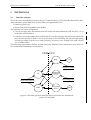
• a client/server relationship between OHS and VCS for the exchange of information; either side may assume the role of client or server, at any time. In the following, the processes providing services are called Template server and Scheduling parameters server (within VCS) and Schedule server (within OHS).
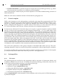
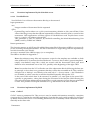
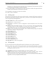
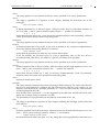
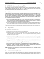
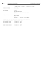
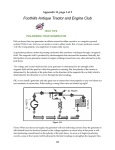
The following figure shows the flow of data among the different clients and servers; note that con‐
trol (command) relationships are not shown.
OHS VCS
BOB
OS
Sequencer scripts
OT
Scheduling
Parameters
Server
Ins Config Files
Observation Blocks
P2PP
Template
Server
OSS
Figure 1: The main processes and data flows involved in the interface be‐
tween VCS and OHS.
6
ICD between VCS and OH - 3
2.2
VLT-ICD-ESO-17240-19200
Common Concepts and Tools1
The basic unit for OHS and the Scheduling tools, and more generally for the entire VLT Data Flow, is the observation block. Although within VCS smaller units exist, VCS obviously needs to be aware of this concept, and must know how to decompose observation blocks into units of its own. Apart from this technical requirement, the end‐user will also want to have at the telescope the same tools at his disposal as the ones he was exposed to during P2PP; so some of these tools may need to be incorpo‐
rated into VCS as well.
An observation block contains a reference to an observation description which in turn contains refer‐
ences to one or more templates. For observation blocks involving target acquisition, the first template is always an acquisition template. This acquisition template will always be executed by VCS, inde‐
pendent of the history of observations, thereby guaranteeing that observation blocks remain inde‐
pendent units and can be reordered by the scheduler2. The subsequent templates in one observation block can each deal with one or more exposures, or can also be acquisition templates if further target acquisition is required within the same observation block. Although there is technically nothing against having several templates within a single observation block, the aim is to keep observation blocks as small and simple as possible, so they remain manageable (and schedulable).
The different components of observation blocks and templates which are known to both OHS and VCS are:
• Observation blocks: during P2PP a set of observation blocks are defined, which are after checking submitted to the Scheduling tools. The VCS retrieves these observation blocks later on, requesting them from OHS applications like P2PP and OT. VCS then needs to break down each observation block in a set of template calls. VCS itself does not allow to build observation blocks. VCS can only modify the observation blocks at the level of template parameters and the setups of individual exposures; i.e., VCS cannot add/remove/rearrange templates nor exposures to/from/of an observation block without invalidating the rest of the data‐flow process. Any modification of template or setup parameters needs to be recorded in the FITS headers.
• Template calls: are either defined with P2PP during the building of observation blocks, or alternatively within VCS at the telescope. The VCS needs to resolve each template call into individual actions, with their corresponding setups.
• Template selector: a GUI which allows to select a particular template name. P2PP does not need to know the contents of the template (standard sequencer script) itself, the name of the file will do (relying on the configuration management control exercised by VCS on these files). This filename plus a short description is part of the template signature file.
• Template Signature File: a file containing a description of the template and its parameters. It gives a.o. the name, the type and the range of the parameters, plus the filename and short description of the template itself. It is written in short hierarchical format.
1. See the glossary in section 1.6 for additional explanation of terms.
2. However, the time needed to execute an acquisition template does depend on the history of obser‐
vations – in the case of two consecutive observation blocks sharing the same target, it is up to the ob‐
server to decide whether to repeat an acquisition or keep the current telescope pointing. This affects the accuracy with which one can estimate the time needed to execute an observation block, and conse‐
quently the precision of the generated short term schedule.
ICD between VCS and OH - 3
2.3
2.3.1
VLT-ICD-ESO-17240-19200
7
Schedule server
Data exchange
The following information must be sent by the OHS at the request of VCS:
• the list of the next few observation blocks to execute.
2.3.2
Location
The Schedule server resides on one of the DFS workstations.
2.4
Phase II procedure
The task of P2PP is to build observation blocks which can then be submitted to the Scheduling Tools. The observation block is a rather complex entity, containing data and methods necessary to execute a set of correlated exposures, involving a single telescope preset. P2PP has the task of com‐
pleting all the information required for an observation block to be executable, and guaranteeing its consistency. However, here we describe only these components of the observation block and P2PP’s actions which are within the scope of this document, i.e. mainly templates and template operations.
A major component of an observation block as an object is the ObservationDescription. As the name implies, this entity describes how the observation must be performed. It is in turn made of one or more template calls. A template call is simply the template name plus a set of values for the template parameters.
To define a template call, the end‐user needs to perform two actions consecutively:
1. select a template;
2. define the values of the parameters with which this template has to be executed. This is done via a template parameter GUI.
Template calls are stored within the observation block.
Values for template parameters can be checked for correctness. Some checks can be performed by checking values against the template signature: type and range checks for individual parameters may can be done this way. More complex checks, involving combinations of parameters, can only be performed by the OSS (via the Template server of the VCS) because they require interaction with the VLT real‐time database.
Note that OHS applications are capable of dealing with templates which can be executed in parallel, and will support parallel execution. The implementation of this support is TBD.
2.5
Scheduling procedure
The OHS operator defines the subset of observing blocks which are eligible for execution during the following night(s); it is activated by the operator before the beginning of the observing night, and whenever there is a change in the instrumental configuration requiring a redefinition of the set of candidate observation blocks.
The OHS operator defines the actual time‐line for the night; rescheduling is activated by any signif‐
icant change in input parameters, like:
• weather conditions;
8
ICD between VCS and OH - 3
VLT-ICD-ESO-17240-19200
• required scheduling strategy (defined by the operator);
• instrumental configuration (signalled by the VCS);
• set of eligible observation blocks (whenever an observation block is started, or the operator has completed a run).
Upon request, OHS transfers observation blocks to the VCS; transfer takes place after OB’s are con‐
verted to an intermediate format (which includes only the relevant information). Intermediate for‐
mat is TBD; transferred information includes: • observation block’s identification information;
• all template calls1;
• all other OB information that must end up in the FITS headers of the generated data frames.
2.6
VCS procedure
Telescope, instrument and detector setup files constitute the most direct interface to operate the VLT. They are loaded by the Observation Software (OS), under control of the operator, and fed to the Telescope, Instrument and Detector Control Software, respectively. Instrument scientists and ob‐
servers/operators can store values for parameters in setup files by means of a user friendly GUI, which is part of the VLT Observation Support Software (OSS). They are then stored in a repository, on disc, for subsequent retrieval by OS.
This rather interactive way of operating an instrument is not the only possible way, as OS can also be run programmatically by the Sequencer. The latter tool can send command sequences to OS. These sequences are stored in ASCII files called Sequencer scripts. The concept of templates and ob‐
servation blocks relies on this capability.
Still, OS itself is not aware of the existence of observation blocks. This means that the observation blocks, handed over to VCS by the Scheduler, must be reduced into single exposures. This happens in two distinct steps, as observation blocks embed templates, which on their turn deal with expo‐
sures.
2.6.1
Observation blocks to templates
An observation block contains a list of template calls, which will be executed sequentially and with‐
out interruption (unless the operator intervenes). A new observation block will not be started during the execution of one OB, with the possible exception of an instrument that can handle two or more observations in parallel (see below). So the sequence of actions from VCS’s point of view is:
1. by default, given the volatility of the schedule, VCS queries OHS every time it is about to start a new observation block; however, in case the link to OHS goes down, more than one OB is requested for. For each observation VCS receives a.o. the list of template calls; these template calls refer to Sequencer scripts and reference setup files which are already available in the VCS;
2. check compatibility of this set of template calls with the current instrument configuration;
3. request the Sequencer to execute the next‐in‐line Sequencer script, with the parameters as indicated in the template call
1. Template calls normally refer to Sequencer scripts and reference setup files which are already avail‐
able to the VCS. Calls to generic templates, however, include the actual setup files and override param‐
eters – see 2.7.
ICD between VCS and OH - 3
VLT-ICD-ESO-17240-19200
9
4. update the status display GUI, indicating which template is currently being executed.
5. upon reception of termination of the template loop back to 3., until the last template is finished; after that, return status information to OHS.
The status is displayed in a tabular form, and this GUI also includes only the following control but‐
tons:
• START: to start the execution of the next selected observation block (usually the first in‐line, unless through standard selection mechanisms another observation block has been selected). • ABORT: to abort as soon as possible the current observation block, i.e. when the currently executing template is finished. Remark that this template is not aborted by force, but is rather informed that the ABORT button was pressed and hence its script should try to terminate/
abort in a clean way. A subpanel allows the operator to specify (a) the reason of the abort action, and (b) whether execution of the OB can/should be repeated.
• PAUSE/CONTINUE: to pause the observation block after termination of the current template; or to continue a paused observation block.
• REPEAT: to signal that the current observation block needs to be repeated. This signals to OHS the operator’s decision, and implies an ABORT if not given before.
Parallelism: There are some instruments which can prepare for a next set of observations without disturbing the ongoing ones. Whenever this preparation lasts a substantial amount of time, it be‐
comes actually a requirement that it takes place ʺin the backgroundʺ, i.e. in parallel with the cur‐
rently ongoing observation block. A typical example is the positioning of fibres on a focal plate, of which there are at least two ‐ one for the ongoing set of observations, and one for the next.
This is dealt with by scanning through the OBs received from OHS for particular keywords, and ex‐
ecuting the corresponding templates in the background.
Whenever the first OB is finished, VCS will anyway request again the set of next OBs to execute. As the OB which will now be on the top of the queue has already gone through (part of) its prepara‐
tion, it will be able to skip that particular phase.
2.6.2
Templates to exposures
The Sequencer receives a request from VCS to execute a particular template, with a corresponding set of parameters. The operation is then as follows
1. receive the template call;
2. check compatibility of this particular template call with the current instrument configuration1;
3. step through the script; this includes sending setup‐ and start‐commands to OS;
4. at the same time, update the status display GUI, indicating at what point of the template the Sequencer currently is.
The Sequencer GUI includes the following control buttons:
• START: to start the execution of the next template.
• ABORT: to abort as soon as possible the current Sequencer script. Remark that this script is not terminated by force, but is rather informed that the ABORT button was pressed and hence should try to abort gracefully.
1. Inclusion of these checks will depend on measured performance
10
ICD between VCS and OH - 3
VLT-ICD-ESO-17240-19200
• PAUSE/CONTINUE: to pause the Sequencer script at the next possible opportunity, e.g. before the next exposure is started; or to continue a paused template.
Other control buttons which may be part of the Sequencer GUI will be disabled during execution of observation blocks.
Note: this GUI can be combined with the GUI described in paragraph 2.6.1
2.7
Generic template
P2PP is only foreseen to work with templates, not directly with setup files as prepared by OSS. This implies a.o. that there are no setup files transferred by the Medium Term Scheduler to the VLT Con‐
trol SW e.g. during preparation of the night, but template calls instead (as part of observation blocks). Templates are designed for a specific mode of observation, so it may seem that OHS and VCS will not be able to deal with any scenario which has not a template designed for it.
For that reason, OHS and VCS also deal with generic templates. A generic template is similar to MOBS (see [2]), in that its list of parameters can be configured interactively ‐‐ i.e., it is a table editor, with one line per observation and one column per parameter. One of the first parameters is always the name of a reference setup file, which gives the defaults for a certain mode of observation. These ref‐
erence setup files are provided by the instrument designers and maintained by ESO; they cannot be modified by P2PP. The additional parameters in the generic template can be individual, specific set‐
up‐parameters, like exposure time. They can also be the names of partial setup files (instrument, de‐
tector and target setup file), which are prepared with OSS. In the latter case it means that several parameters are grouped together in a file. Individual parameters are specified explicitly to override values contained either in the reference setup file or the partial setup files. Obviously, in case there are no partial setup files prepared with OSS, the number of columns in this generic template table will depend on the complexity of the instrument and the mode of observation.
The GUI for the parameters of this generic template is the MOBS table editor (see [6]). The corre‐
sponding Sequencer script is to execute all exposures sequentially, without imposing any condition.
For generic templates the exposure time must be explicitly specified as a parameter of the template (i.e. computed may not be used as the value of tpl.execTime ‐ see Appendix A).
2.8
2.8.1
Exchanged files
File names
The following files are involved in the preparation and/or execution of observation blocks, and available at P2PP/OT and VCS level. To facilitate the selection (filtering) of these files, they have all to be created with particular extensions, according to their type.
1. template signature file: <templateName>.tsf
2. Sequencer script: <templateName>.seq
3. Observation Block Description: <anyName>.obd
4. template reference setup file: <anyName>.ref
5. instrument configuration file: <instrName>.cfg
where <templateName> is the basename for that template, used as first part for all files belonging to a particular template.
ICD between VCS and OH - 3
VLT-ICD-ESO-17240-19200
11
The reference setup file belonging to a certain template is not required to have the same basename, as its name is kept in the template signature file. Its name just has to conform to the rules specified in [2], which require a .ref extension.
2.8.2
File contents
1. The Template Signature File is written in the parameter file format, whose semantics and syntax is determined by the DICB, and described in [2]. Every record in this file is conforming to the short hierarchical format. TSFs are described in Appendix A.
2. The Sequencer script is in the Sequencer language – see [3].
3. The Observation Block Description file is described in Appendix C
4. The Template Reference Setup file is described in [2]. 5. The Instrument Configuration File is described in [2].
12
ICD between VCS and OH - 3
VLT-ICD-ESO-17240-19200
ICD between VCS and OH - 3
3
VLT-ICD-ESO-17240-19200
13
SOFTWARE INTERFACE
3.1
Introduction
The functionality described by the API below makes use of the CCS Message System Interface (see [3]), both on the VCS and the OHS side.
Tcl/Tk clients will request services via the seq_msgSendCommand(n) function; clients written in other languages will use a language‐specific API. Servers will package the requested information as an ASCII string and simply return it, or – should the string be longer than 8KB – they will subdivide it in smaller chunks, to be returned with seq_msgSendReply(n).
Clients will finally concatenate all results obtained with seq_msgRecvReply(n) and/or whatever is returned by the command: the resulting string is the requested service. Error codes are returned by the seq_msgRecvReply(n)function itself.
3.2
Transfer policy
The transfer of information between OHS and VCS is governed by two policies:
• client‐server: one side requests information, and waits synchronously until information is returned, or some transfer error condition arises. Both OHS and VCS may act as servers to the other side; for instance, OHS may query the VCS for the current dynamic configuration of an environment; VCS may request OHS to return the list of the next observation blocks to execute.
Interface functions conforming to this policy are collected in section 3.3 below.
• asynchronous: one side transfers information to the other side, without prior request, and without further action on either side. It is expected that only the VCS will signal asynchronous events to OHS: for instance, VCS may inform OHS that it started the execution of an observation block. Interface functions conforming to this policy are collected in section 3.4 below.
14
ICD between VCS and OH - 3
3.3
VLT-ICD-ESO-17240-19200
Client‐server
Server processes are BOB, the Template server and Scheduling parameters server (part of VCS) and the Schedule server (part of OHS); OHS does not provide run‐time services to the other elements. The fol‐
lowing table summarizes the client‐server API: the Server ID column specifies the string used to identify the server process at run time1.
Client
Server
Server ID
Services
OHS
Template
bob
GetPAF
VCS
Schedule
schedule
NextObsBlocks 3.3.1.1
1. This scheme applies to the current CCS based implementation. Actually, this name can have its Unix process‐id appended to it, or also have a completely different name, depending on which parameters this process received as run‐string. The exact name is given by the parameter process‐name of the PAFReady event (sec. 3.4.3).
ICD between VCS and OH - 3
3.3.1
VLT-ICD-ESO-17240-19200
15
Functions implemented by the Schedule server
3.3.1.1 NextObsBlocks
NextObsBlocks: List of the next observation block(s) to be executed.
Input parameters: num
Integer number of observation blocks requested
offline
Optional flag: can be either true or false (case insensitive); defaults to false (not off‐line). If the value of this flag is true, then the OBs are requested for off‐line execution; that is, not an on‐line instrument. OHS applications will then ignore all ObsBlockStatus and TemplateStatus events (secs. 3.4.1 and 3.4.2) relative to those OBs.
This parameter is used, for instance, by the BOB controlling the Mask Manufacturing Unit (MMU) used by FORS2 and VIMOS.
Return parameters: This function returns an ASCII text file called Observation Block Descriptor (OBD) in parameter file format, including the standard headers. The file is returned as a single string; lines are separated by newline characters (ASCII 0x20).
An error is returned if the OBD is empty (i.e. no templates).
The OBD is described in Appendix C.
Note: that reference setup files and sequencer scripts for the template are available on both sides (OHS and VCS) and need not be transferred ‐‐ however, the so called “generic templates” employ user‐defined setup files, which are stored with the observation block and need therefore to be transferred over to the VCS, possibly at the beginning of the night. TBD.
Note: It is unclear how the VCS will make use of the observation blocks following the first one: in principle, in fact, there is no guarantee that they will be the executable at all. They could be thought of as a “backup” set of blocks, to be used only if — for any reason — the Scheduler is not available, in which case they would be scheduled manually through the VCS.
In the case of OBs which have to be executed ʺin parallelʺ (i.e. some part of the second OB ‐ typically its preparation ‐ takes place during the execution of the first) the OBs following the first one will include additional information like a rough estimate of when they are scheduled to start. This permits to anticipate estimates for e.g. the airmass at the start of this OB. 3.3.2
Functions implemented by BOB
3.3.2.1 GetPAF
GetPAF: return a parameter file. This service is used to transfer information created by a template script on the VCS side back to an OHS application. Note that the reply could possibly get chopped up before transmission due to CCS buffering limitations, but re‐assembly can be taken care of auto‐
matically at the client side.
Parameters:
16
ICD between VCS and OH - 3
VLT-ICD-ESO-17240-19200
pathname
Absolute pathname of the parameter file.
transient
Flag: PAF is transient; allowed values are true and false (case insensitive).
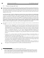
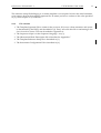
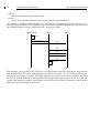
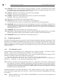
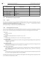
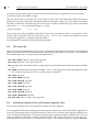
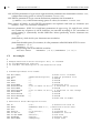
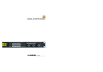
This request is usually issued in response to a PAFReady event originating from the VCS (sec. 3.4.3). The event is generated by some template script when it has completed preparing the parameter file; the complete chain of events is depicted in the “event trace” below.
Template script
BOB
OHS
build PAF
"PAF is ready..."
(return)
PAFReady
GetPAF
PAF0
PAF1
PAFn
delete PAF
The template script produces the PAF file to be transferred to the OHS application, then informs BOB that the PAF file is ready. BOB generates a PAFReady event (sec. 3.4.3) to inform the OHS appli‐
cation that such a file is available. The OHS application can then request that parameter file using the GetPAF service: BOB will transfer (possibly chopping the file up in sections, as shown in the dia‐
gram). If the transfer completes successfully, and if the file was declared “transient”, BOB will then delete it to avoid cluttering its disk space.
ICD between VCS and OH - 3
3.4
VLT-ICD-ESO-17240-19200
17
Asynchronous
The following table summarizes the asynchronous API.
3.4.1
From
To
Message
VCS
OHS
ObsBlockStatus 3.4.1
VCS
OHS
TemplateStatus3.4.2
VCS
OHS
PAFReady 3.4.3
ObsBlockStatus
ObsBlockStatus: The status of an observation block has changed1, either as the result of its automatic execution, or triggered by operator intervention.
Parameters:
Observation block identification: this is the value of the OBS.ID keyword (see NextObsBlock, 3.3.1.1).
Timestamp: the UTC value returned by the VLT Time System, as a time‐string in the ISO format. Format: “ccyy-mm-ddThh:mm:ss.ff”.
NewStatus: one of the following:
VERIFYFAIL: verification of OB failed, execution cannot be started; message information includes an error code describing which OB information item failed verification.
STARTED: execution of OB started.
PAUSED: OB execution was suspended.
CONTINUED: OB execution was resumed after suspension.
ABORTED: OB execution was interrupted and cannot be resumed; message information includes a textual description of the reason.
MUSTREPEAT: OB execution couldn’t be completed and should be restarted later; message information includes a textual description of the reason.
TERMINATED: OB completed successfully.
CONFIGURED: the instrument was configured, the OB was effectively not executed..
Message: a text message (meaningful only when NewStatus is one of VERIFYFAIL ABORTED or MUSTREPEAT)
The parameters are returned as Tcl list of strings. For instance:
1. The Scheduler might possibly like to receive intermediate progress messages so that the remaining execution time of an OB can be better estimated. However, since the Scheduler does not look at the contents of an OB, this is another tricky question. It could be interesting to let the Scheduler compare, at the level of single templates, the expected execution time and the actual one. From the difference, (i) the Scheduler might, then, be able to refine its estimates in the more objective and realistic way and (ii) the Observatory could recognize trends and patterns in the operating efficiency.
18
ICD between VCS and OH - 3
VLT-ICD-ESO-17240-19200
125672 1997-11-05T23:34:45.67 VERIFYFAIL “Value out of range”
3.4.2
TemplateStatus
TemplateStatus: The status of a template has changed.
Parameters:
Observation block identification: value of the OBS.ID keyword (see Appendix C).
Template identification: sequence number of the Template within the OB (1, 2, 3,...).
Timestamp: the UTC value returned by the VLT Time System, as a time‐string in the ISO format. Format: “ccyy-mm-ddThh:mm:ss.ff”.
NewStatus: one of the following:
STARTED: execution of template started (no ExtraInfo).
ABORTED: template execution was interrupted and cannot be resumed; ExtraInfo includes a textual description of the reason.
MUSTREPEAT: template execution couldn’t be completed and should be restarted later; ExtraInfo includes a textual description of the reason.
TERMINATED: template completed successfully. Normally no ExtraInfo: however, in the case of an acquisition template, ExtraInfo includes the acquired coordinates (RA and Dec)
ExtraInfo: depends on NewStatus
The parameters are returned as Tcl list of strings. For instance:
671 1 1997-11-05T23:34:45.67 TERMINATED 033473.1 -734427.6
3.4.3
PAFReady
PAFReady: a parameter file is available for download. This event usually triggers a GetPAF request, see sec. 3.3.2.1 for details.
Parameters:
env‐name
Name of the environment to query.
process‐name
Name of the process to query.
pathname
Absolute pathname of the parameter file.
transient
Flag: PAF is transient; allowed values are true and false (case insensitive).
The parameters are returned as list of strings. For instance:
PAFReady wusg1 bob /tmp/my-file.paf true
ICD between VCS and OH - 3
A
A.1
VLT-ICD-ESO-17240-19200
19
APPENDIX: Template Signature Files
Introduction
Template Signature Files (TSFs) describe an observing template’s interface (or API) ; that is, its type and parameters, plus some other description and housekeeping information. This information is sufficient to call the template from within an Observation Block, but it does not include the se‐
quencer script implementing the template, nor its reference setup data. In this Appendix we de‐
scribe the format and structure of Template Signature Files, first by giving a small example, then proceeding to describe a TSF’s structure and the meaning of its keywords.
A.2
An example
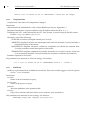
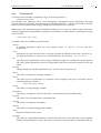
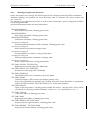
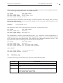
The easiest way of describing a TSF is probably that of presenting an example. Here we show an ex‐
ample template for SUSI: the file is a set of keyword/value pairs in parameter file format (see [2] for a description of the syntax).
#
# Template signature file for SUSI_img_calib_FlatField
#
PAF.HDR.START
PAF.TYPE
“Template Signature”;
# Type of parameter file
PAF.ID
“$Id: SUSI_img_calib_FlatField.tsf,v 1.1 1996/07/23$”
PAF.NAME
“SUSI_img_calib_FlatField”;
# Parameter file NAME
PAF.DESC
“Example Template Signature File”;
PAF.CRTE.NAME “A M Chavan“;
# Who created par. file
PAF.CRTE.DAYTIM
“12-Jul-96“;
# Date and time of creation
PAF.LCHG.NAME
“A M Chavan“;
# Who did last change
PAF.LCHG.DAYTIM
“23-Jul-96“;
# Date and time of last change
PAF.CHCK.NAME
“checksum.exe“;
# Appl. checking par. file
PAF.CHCK.DAYTIM
“23-Jul-96“;
# Date and time of last check
PAF.CHCK.CHECKSUM
“aG10y76TT5fdghsfgaKXf“;# Parameter file checksum
PAF.HDR.END
TPL.INSTRUM
TPL.MODE
TPL.VERSION
TPL.REFSUP
TPL.PRESEQ
TPL.GUI
TPL.TYPE
TPL.EXECTIME
TPL.DID
TPL.OVERHEAD
TPL.RESOURCES
“SUSI”;
# This is a template for SUSI
““;
# Not applicable for SUSI
“0.1 alpha”;
# (any string)
“SUSI_img_calib_FlatField.ref”;# Reference setup file
“SUSI_img_calib_FlatField.seq”;# Sequencer script
““;
# reserved
“science”;
# science, calib, ...
“computed”;
# can be “computed” or a number
“ESO-VLT-DIC.TPL-1.0”;# currently ignored
“”;
# reserved
“”;
# reserved
# NOTE
#
The following list of parameters should be ordered so that
#
those parameters which are most likely to be changed by the user
#
appear at the top!
#
This will make the user interface easier to operate.
20
ICD between VCS and OH - 3
VLT-ICD-ESO-17240-19200
#############################################################
# LABEL and MINIHELP keywords help the user understand the template
TPL.PARAM
“DET.UIT1”;
DET.UIT1.TYPE
“intlist”;
DET.UIT1.RANGE
“1..10000”;
DET.UIT1.DEFAULT
“1”;
DET.UIT1.LABEL
“Exposure time”;
DET.UIT1.MINIHELP
“Exposure time in seconds; min. 1, max. 10000”;
#############################################################
# READOUTMODE has the obsolete TARGIND keyword
TPL.PARAM
“DET.READOUTMODE”;
DET.READOUTMODE.TYPE
“keyword”;
DET.READOUTMODE.RANGE
“slow fast”;
DET.READOUTMODE.DEFAULT “slow”;
DET.READOUTMODE.TARGIND "T";
# OBSOLETE, to be phased out
#############################################################
# BINNING has the VALUE keyword; it is a constant parameter
TPL.PARAM
“DET.BINNING”;
DET.BINNING.TYPE
“integer”;
DET.BINNING.VALUE
“1”;
# 1-1, 1-2, 1-4, 1-8
#############################################################
# CCDWINDOW’s RANGE and DEFAULT keywords query the instrument
TPL.PARAM
“DET.CCDWINDOW”;
DET.CCDWINDOW.TYPE
“intrect”;
DET.CCDWINDOW.RANGE
“QUERY-INST getCCDWindow”;# Query instrument
DET.CCDWINDOW.DEFAULT
“QUERY-INST getCCDWindow”;# Query instrument
#############################################################
# POSANG’s RANGE is -9999 and any number between 0 and 360 (excluded)
TPL.PARAM
“DET.POSANG”;
DET.POSANG.TYPE
“number”;
DET.POSANG.RANGE
“-9999 0..359.99”
DET.POSANG.DEFAULT
“0”
#############################################################
# There is no default filter
TPL.PARAM
“INS.FILTER”;
INS.FILTER.TYPE
“keyword”;
INS.FILTER.RANGE
“QUERY-INST getFilters”;# Query instrument
INS.FILTER.DEFAULT
““;
#
A.2.1
PAF keyword length limits
The DICB document specifies — if rather vaguely — the maximaum length of PAF keywords. Clar‐
ifications have been requested to DICB; in the meantime however, both the OHS and the VCS shall respect the following conventions.
Categories (like INS): 3 letters
Subsystems (like TARG): ʺgenerally maximum 4 charactersʺ, not including numeric index some subsystems may require (OPTI1, OPTI2,...).
ICD between VCS and OH - 3
VLT-ICD-ESO-17240-19200
21
Maximum two of these subsystems keywords can be concatenated. That restriction is (at least) for all the keywords that end up in the FITS headers.
Parameters (like NAME): ʺas FITS primary keywords, max 8 chars, whereby only uppercase letters, unmbers, dash and undescore characters are allowedʺ.
So an expample of a maximum size keyword would be:
CAT.SUBS1.SUBS2.PARAMETE
A.3
PAF keywords
Since TSFs are in parameter file (PAF) format, the file includes a standard PAF header, described in the DICB document about parameter (setup) files: [2]. However, most standard PAF header key‐
words are ignored by OHS applications. PAF.HDR.START: Has no value, and is ignored.
PAF.TYPE: Must be “Template Signature”.
PAF.ID: Ignored. It should be used for configuration control information, like TSF revision number, etc.
PAF.NAME: Identifies the template. Example: “SUSI_img_calib_FlatField”. This string should follow the naming scheme for TSFs described in [2], and it must match the pathname of the TSF (which in this case is SUSI_img_calib_FlatField.tsf), without the .tsf extension. PAF.DESC: One‐line description of the template, used to build mini‐help strings for interactive applications. Example: “Twilight flat fields”.
PAF.CRTE.NAME: Ignored.
PAF.CRTE.DAYTIM: Ignored.
PAF.LCHG.NAME: Ignored.
PAF.LCHG.DAYTIM: Ignored.
PAF.CHCK.NAME: Ignored.
PAF.CHCK.DAYTIM: Ignored.
PAF.CHCK.CHECKSUM: Ignored.
PAF.HDR.END: Has no value, and is ignored.
A.4
TPL keywords
TPL keyword/value pairs describe template‐specific information; none of them are ignored.
Note: there will be some specific TPL keywords needed to deal with parallel templates (see sections 2.4 and 2.6.1). They are not yet included in this section. This document will be updated as DICB approves these keywords.
TPL.INSTRUM: Instrument for which the template was written. Example: “SUSI”.
TPL.MODE: Instrument mode for which the template was written. Example: “RILD”. TSFs for modeless instruments, like SUSI, should set this keyword to the empty string (““).
This keyword and its value will be extracted from the TSF and inserted into the OBD (see Appendix C) for every template the OBD contains.
22
ICD between VCS and OH - 3
VLT-ICD-ESO-17240-19200
TPL.VERSION: Version of the template (a string). Example: “0.1 alpha”. Note that this value should be updated with every new version of the TSF, and should be managed through some source file control system, like CMM, RCS, SCCS or CVS.
TPL.REFSUP: Pathname of the reference setup file for the template. Example: “SUSI_img_calib_FlatField.ref”.
TPL.PRESEQ: Pathname of the predefined sequencer script file for the template. Example: “SUSI_img_calib_FlatField.seq”.
TPL.GUI: Reserved: should be set to the empty string (““).
TPL.TYPE: Must be one of: science, calib, acquisition, test, and generic.
It can also be parallel or offline, in which case no data (FITS files) will be generated.
TPL.EXECTIME: expected execution time of the template in seconds: can be either a number or the word computed. In the latter case, the expected execution time is computed according to a standard algorithm, which requires the template to have one of a number of specific parameter combinations (see sec. A.6).
TPL.OVERHEAD: Reserved: should be set to the empty string (““).
TPL.DID: Name of the template dictionary used to write this Template Signature File. It is currently ignored, but will be used in future releases to check consistency across the interfaces.
TPL.RESOURCES: Reserved: should be set to the empty string (““).
A.5
Template parameters
The third, and usually largest, group of keyword/value pairs define the template’s parameters. Each parameter is described by a standard group of keywords, which define the parameter’s name, type, allowed range, etc. Note that the list of template parameters should be ordered so that parameters which are most likely to be changed by the user appear at the top. This will make the user interface easier to operate.
A.5.1
TPL.PARAM keywords
Each parameter is introduced by a TPL.PARAM keyword; its value is a string — the name of the pa‐
rameter — and is in turn a PAF keyword. Example: “DET.READOUT.MODE”. The first sub‐keyword of the parameter name (“DET” in the example) identifies the category of the parameter. Allowed values for a parameter’s category are:
ADA AOS COU DEL DETi DPR INS ISS LGS OCS PAF SEQ TEL TPL
where DETi stands for any one of DET, DET1, DET2, etc. Only uppercase characters, numerals, un‐
derscore (“_”), and dot (“.”) are allowed in a parameter’s name.
Note: All these categories can in principle have indices (i.e. when there is more than 1 subsystem of that category), and this is explicitly permitted by the DICB document. Until recently, the DET category was the only case now where these indices appear. However, this may soon change, as we’ll have to do with instruments like FLAMES which can deal with GIRAFFE, UVES nd the Fibre Positioner simultaneously.
Template parameters are further described by TYPE, RANGE, DEFAULT, VALUE, LABEL, and MINIHELP keywords (a further keyword, TARGIND, is allowed for backwards compatibility, but should be avoided). Note: RANGE, DEFAULT, VALUE, LABEL, and MINIHELP keywords can be also expressed as ISF references (sec. B.5).
ICD between VCS and OH - 3
A.5.2
VLT-ICD-ESO-17240-19200
23
TYPE keywords
TYPE keywords describe a parameter’s type, and are expressed as:
parameter‐name.TYPE
For example, DET.READOUT.MODE.TYPE. Specifying a parameter’s type is mandatory; the type implies a set of legal values (thus driving the verification routines — see the discussion of RANGE
keywords below), and which widgets will be used to build the user interface.
Note: some of the parameter types are defined as being lists, or sequences. Unless written otherwise, sequence elements are separated by whitespace: for instance, a valid value for a parameter of type intlist could be
1200 1200 600 1200
Available values for TYPE keywords include:
boolean
A boolean parameter which can only assume values “T” and “F”, for true and false, respectively.
coord
Parameters of type coord are used to express celestial coordinates in the form “hh:mm:ss.sss” (for right ascension) or “dd:mm:ss.sss” (for declination). For instance, -09:31:43.80. file
The value of file parameters is a text string of arbitrary length. No verification is performed on the value of these parameters; the GUI widget allows the user to load the content of a file, and edit it.
filename
These parameters hold file pathnames, like “/home/forsteam/setup/slit1.paf”.
intlist
The value is a sequence of integer numbers.
intrect
The value of intrect parameters is a sequence of four integers: this type is normally used to represent detector windows:
min‐x min‐y max‐x max‐y
integer
The value is a single integer number.
keywordlist
The value is a sequence of keywords, that is, words taken from a predefined list.
keyword
The value is a word taken from a predefined list.
numlist
The value is a sequence of numbers.
number
The value is a single floating‐point number.
object
Reserved: should not be used.
paramfile
The value of a paramfile parameter is ASCII text taken from a disk file, like a file parameter. Unlike a file parameter, however, the syntax of such text must be that of a Parameter File [2]. 24
ICD between VCS and OH - 3
VLT-ICD-ESO-17240-19200
Some special keywords allow OHS and VCS applications to extract information from the text.
TSF parameters of type paramfile are described in more detail in sec. A.8.
pixel
These parameters hold pixel (detector) positions, represented as a pair of integers.
string
The value is a string of ASCII characters.
target
Reserved: should not be used.
A.5.3
RANGE keywords
A template parameter’s value is checked at veriouis stages against its legal range, and an error alert is issued if the verification process fails. RANGE TSF keywords describe the allowed range for a pa‐
rameter’s value, and are expressed as:
parameter‐name.RANGE
For example, DET.READOUT.MODE.RANGE. The specification of a parameter’s legal range depends on its type, as explained below. Note: if the RANGE of a parameter is the empty string (““), any value of the same type as the pa‐
rameter will be accepted as a legal value. For example, if the TYPE of a parameter is integer, and its RANGE is the empty string, then any integer will be interpreted as a legal value. The RANGE keyword is mandatory for all parameter types, with the followig exceptions, in which case it should not be given:
(a) boolean parameters;
(b) parameters for which a VALUE keyword is also given (see below).
boolean
The range of a boolean parameter is implicitly defined by its type; the RANGE keyword for these parameters should be omitted (it will be ignored, in any case).
coord
The range of a coord parameter should be set to ra, if the value is a right ascension, or dec, otherwise. Note: in the current version of the OHS applications the range of a coord parameter is ignored, and the name of the parameter is used to infer whether the value should be considered a right ascension (for TARG.ALPHA parameters) or a declination (for TARG.DELTA).
file
No verification is performed on the value of these parameters; however, the value of the RANGE keyword is used to configure the File Selection Box used by the GUI widget. So, for instance, if the RANGE of a file parameter is *.fims, only files with the .fims extension will be displayed in the FSB (P2PP V.1.2.2 or later).
Note that the Unix convention *.* is not supported on the OHS side, and should not be used: please use an empty string to indicate “any file”.
filename
No verification is performed on the value of these parameters; however, the value of the RANGE keyword is used to configure the File Selection Box used by the GUI widget. So, for instance, if the RANGE of a filename parameter is *.tsf, only files with the .tsf extension will be displayed in the FSB (P2PP V.1.2.2 or later).
ICD between VCS and OH - 3
VLT-ICD-ESO-17240-19200
25
intlist
The range applies to every element in the list, and is specified as for integer parameters. intrect
The range is specified as a sequence of four integers, defining the maximum size of the rectangle:
min‐x min‐y max‐x max‐y
integer
A blank‐separated list of allowed values. Allowed values may be individual numbers or min..max pairs — that is, pairs of numbers joined by the ʺ..ʺ symbol. For instance: -1 0 1..5 8
means that allowed values are ‐1, zero, 8 and any number between 1 and 5 (included). Allowed values don’t need to be specified in increasing order.
keywordlist
The range applies to every element in the list, and is specified as for keyword parameters. keyword
A blank‐separated list of keywords. A keyword is defined as any sequence of alphanumeric characters without intervening blanks. For instance: slow normal fast
means that the parameter can take any one of those three values.
If the list includes the keyword Special (case is significant), then in fact any value is considered valid. This allows, for instance, “special” user filters to be specified.
numlist
The range applies to every element in the list, and is specified as for number parameters. number
A blank‐separated list of allowed values. Allowed values may be single numbers or min..max
pairs ‐‐ that is, pairs of numbers joined by the ʺ..ʺ symbol. For instance: -1 0 1..2.5 3.5
means that allowed values are ‐1, zero, 3.5 and any number between 1 and 2.5 (included). Allowed values don’t need to be specified in increasing order.
object
Reserved: should not be used.
paramfile
The value of these parameters must be a text string in PAF format [2]. The value of the RANGE
keyword is used instead to configure the File Selection Box used by GUI widgets. So, for instance, if the RANGE of a paramfile parameter is *.mmo, only files with the .mmo extension will be displayed in the FSB.
Note that the Unix convention *.* is not supported on the OHS side, and should not be used: please use an empty string to indicate “any file”.
TSF parameters of type paramfile are described in more detail in sec. A.8.
pixel
The range is specified as a sequence of four integers, defining the rectangle within which the pixel may be:
min‐x min‐y max‐x max‐y string
A blank‐separated list of allowed values. Allowed values may be individual strings or min‐max
pairs — that is, pairs of strings joined by a dash (ʺ‐ʺ). For instance: alpha bravo-echo zero
means that allowed values are alpha, zero, any string that is lexicographically in between bravo
26
ICD between VCS and OH - 3
VLT-ICD-ESO-17240-19200
and echo (included); case is significant, so that Delta is not within this list of allowed values. Allowed values don’t need to be specified in any order.
target
Reserved: should not be used.
A.5.4
DEFAULT keywords
DEFAULT keywords describe the default value for a parameter’s value, and are expressed as:
parameter‐name.DEFAULT
In the example, DET.READOUT.MODE.DEFAULT. The default value of a parameter should in gener‐
al belong to the parameter’s legal range; however, when no reasonable default value exists, this key‐
word should be set to the NODEFAULT string.
The DEFAULT keyword is mandatory for all parameter types, unless a VALUE keyword is also giv‐
en (see below), in which case it DEFAULT keywords will be ignored and should not be given.
Note: a DEFAULT keyword can be also expressed as an ISF reference (see B.5).
A.5.5
VALUE keywords
VALUE keywords describe the assigned value for a parameter’s value, and are expressed as:
parameter‐name.VALUE
For example, DET.READOUT.MODE.VALUE. Parameters for which a VALUE keyword is given are effectively constant and read‐only, only assuming the specified value. In fact, such parameters are not even displayed on OHS interactive GUIs. If a VALUE keyword is given, RANGE and DE‐
FAULT keywords (see above) will be ignored, and should not be given; the parameter will not ap‐
pear in the OBD (see Appendix C).
A.5.6
LABEL keywords
LABEL keywords allow to specify a label to be displayed next to a parameter’s entry widget on OHS GUIs; they are are expressed as:
parameter‐name.LABEL
For example, DET.READOUT.MODE.LABEL. LABEL keywords are not mandatory: if a LABEL key‐
word is not given, the parameter name (stripped of the category subkeyword; like DET, INS, etc.) will be used to label the entry widget, leading to less user‐friendly template parameter GUIs. Param‐
eter labels should be expressive and concise, in order not to take up too much screen space.
Template developers are strongly encouraged to provide LABEL keywords for all parameters.
A.5.7
MINIHELP keywords
MINIHELP keywords allow to specify a string to be displayed in the mini‐help area of the OHS ap‐
plications when the mouse cursor enters a parameter’s entry widget; MINIHELP keywords are are expressed as:
parameter‐name.MINIHELP
For example, DET.READOUT.MODE.MINIHELP. MINIHELP keywords are not mandatory: if the keyword is not given, a brief standard minihelp string will be displayed for that parameter, leading to less user‐friendly template parameter GUIs.
Template developers are strongly encouraged to provide MINIHELP keywords for all parameters.
ICD between VCS and OH - 3
A.5.8
VLT-ICD-ESO-17240-19200
27
HIDE keywords
HIDE keywords can be used to turn off the display of the parameter in the GUI of OHS applica‐
tions. HIDE keywords are are expressed as:
parameter‐name.HIDE
For example, INS.ADP1.HIDE. HIDE keywords are not mandatory: if the keyword is not given, or its value is empty, the parameter will be displayed by all OHS applications. If the value is OHS, the parameter will not be displayed by any OHS application.
If the value is P2PP, OT, etc, the corresponding application will not display the parameter in any of its GUIs.
A.6
Estimating an Observation Block’s execution time
This section was obsolete and therefore removed.
A.7
TEL.TARG parameters in Acquisition templates
Because of the special structure of the Observation Blocks handled by the Data Flow System, TEL.TARG parameters of Acquisition Templates are given a special treatment within OHS applica‐
tions. Such parameters describe the astonomical body to be acquired and observed, just like the Target attached to each Observation Block. This implied having duplicated and possibly inconsis‐
tent information, and it was decided to leave the astonomical body description only within the Tar‐
get object, and to hide TEL.TARG parameters from the OB author. When preparing an OBD file (see Appendix B), values extracted from Target fields are used to initialize the Acquisition template pa‐
rameters.
The following table describes the correspondence between TEL.TARG parameters and Target fields. Parameters found in the leftmost column will not be displayed in the Acquisition Template parameter GUI.
Note:
MOS Acquisition Templates for instruments like FORS1/FORS2 and VIMOS/NIRMOS, which retrieve Target information from special setup files, should not include any of the following parameters in the Acquisition Template Signature Files.
Parameter name
Target field
TEL.TARG.ALPHA
Right ascension
TEL.TARG.RA
Right ascension
TEL.TARG.DELTA
Declination
TEL.TARG.DEC
Declination
TEL.TARG.EPOCH
A number like “2000.0”
TEL.TARG.EQUINOX
A string like “J2000”
TEL.TARG.PMA
Proper motion in right ascension
TEL.TARG.PROPRA
Proper motion in right ascension
Notes
Target coordinated are not always given in J2000
28
ICD between VCS and OH - 3
Parameter name
VLT-ICD-ESO-17240-19200
Target field
TEL.TARG.PMD
Proper motion in declination
TEL.TARG.PROPDEC
Proper motion in declination
TEL.TARG.COLOR
Color
TEL.TARG.MAG
Magnitude
TEL.TARG.NAME
Name
A.8
A.8.1
Notes
TSF parameters of type paramfile
Syntax
The value of a parameter of type paramfile is ASCII text, and it must conform to PAF file syntax (see [2]). However, newlines and double quotes are escaped (as “\n” and “\”” respectively), so that in practice the contents of this file is seen as a string.
The empty string is a valid value for a paramfile parameter.
A.8.2
Meaningful header keywords
Keywords PAF.HDR.START and PAF.HDR.END are needed for syntactical completeness, and they have no value. The following keywords might be processed by OHS applications and/or BOB: PAF.TYPE
Must be Paramfile PAF.NAME
Must be the file’s basename. For instance: cluster‐a.adp. PAF.DESC
Can be empty. Normally used to store a short description of the file. PAF.CRTE.NAME
Must be set to the name and version number of the application generating the file, separated by whitespace: for instance:
FIMS 1.5p2
PAF.CRTE.DAYTIM
Must be set to the date and time the paramfile file was generated, encoded according to the ISO conventions. For instance: 1999-10-21T20:17:45.000 PAF.CHCK.CHECKSUM
Can be empty. If it is not empty, it must be set to a checksum string, computed according to the FITS Checksum proposal by Seaman and Pence, 1995 (see http://archive.eso.org/
dicb/checksum/).
PAF.ID
This should be some unique ID, based for instance on the current time and date and process ID, etc. Can be used by operation teams to track problems. All other PAF header keywords are ignored by OHS applications, although other components of the VCS or DFS may require them as well.
ICD between VCS and OH - 3
A.8.3
VLT-ICD-ESO-17240-19200
29
Meaningful application keywords If they are found in the paramfile, the following keywords will be processed by P2PP as indicated.
Alternate spellings are possible for some keywords, like for instance TEL.TARG.ALPHA and TEL.TARG.RA. The precise set of supported keywords, as well as their actual name, can be configured in P2PP’s site.cf configuration file. See the documentation there for more information.
SIM.ATM.AIRMASS
Max airmass constraint, a floating‐point value. SIM.ATM.ZSEEING Max seeing constraint, a floating‐point value. SIM.ATM.ALTSTREHL
Strehl ratio constraint, a floating‐point value. currently not configured
Fractional lunar illumination (FLI) constraint, a floating‐point value. currently not configured
Moon distance constraint, an integer value. currently not configured
Sky transparency constraint, a string (unchecked). currently not configured
Telescope tempereature constraint, an integer value. currently not configured
Water vapour constraint, a string (unchecked). TEL.TARG.ALPHA, TEL.TARG.RA
Right ascension of the target, like 120036.780 TEL.TARG.DELTA, TEL.TARG.DEC
Declination of the target, like ‐544109.000 TEL.TARG.EQUINOX
The reference date for a coordinate system, like J2000 TEL.TARG.NAME
Can be left empty, will be used on the display panel(s) only. Note: if the paramfile text includes any of these keywords, there should be no parameters called TEL.TARG.ALPHA, TEL.TARG.DELTA, etc., in the same template. TEL.TARG.EPOCH
Epoch of the observation, a floating‐point number like 1999.5. Only the first 6 chars will be considered (i.e. the string will be truncated), so that 1999.55 is equivalent to 1999.5
TEL.TARG.COLOR
Color of the object, a floating‐point value.
TEL.TARG.MAG
Magnitude of the object, a floating‐point value.
TEL.TARG.PRORA, TEL.TARG.PMA
Proper motion in right ascension, a floating‐point value.
TEL.TARG.PRODEC, TEL.TARG.PMD
Proper motion in declination, a floating‐point value.
30
ICD between VCS and OH - 3
VLT-ICD-ESO-17240-19200
TPL.FILE.DIRNAME
This keyword is mandatory. The paramfile text is saved to disk by BOB, and this keyword specifies where. If it is empty, the corresponding disk file will be created in the $INS_ROOT/
$INS_USER/MISC directory. Otherwise, the value of this keyword must be the absolute pathname of the directory in which the disk file will be created. The complete pathname for the disk file will be constructed by appending a forward slash (the ʺ/ʺ characterfs) and then the value of the PAF.NAME keyword to the value of this keyword; in other words, the pathname to use is decided by the observation preparation tool and is written within the file itself. Some environment variables will be resolved by BOB at run time. (Variables resolved by BOB at runtime include: $INS_ROOT, $INS_USER, $TCLTK_ROOT, $INTROOT, $VLTROOT, etc.) For instance: if this keyword is set to the value $INS_ROOT/tmp, and PAF.NAME is myfile.adp, and the $INS_ROOT environment variable, in the environment where BOB is running, is set to /insroot, then the text file will be created as: /insroot/tmp/
myfile.adp
If a file with that pathname already exists, BOB will attempt to overwrite it; in that case, an error may be raised; for instance, if file permissions are not sufficient. BOB will also return an error message if (a) for some reason the file cannot be created (write permission error, non‐existing directory, etc.), or (b) if the resulting pathname is not within the directory subtree rooted at $INS_ROOT. In other words, BOB will not permit to execute such OBs, and may even not display their contents.
Note also that BOB may delete all files created through this mechanism; see the definition of the TPL.FILE.KEEP keyword. TPL.FILE.KEEP
Boolean, indicating whether the file needs to be kept (because it may be needed by subsequent OBs). In the absence of this keyword, or if it is set to ʺFʺ, BOB will delete this file as soon as the OB finishes. If this keyword is set to ʺTʺ, BOB will not do any file clean‐up, shifting this responsibility then to the user/ operator. A.8.4
Displaying paramfile parameters
A.8.4.1 BOB
In the BOB GUI, the value displayed for parameters of type paramfile is the value of the TPL.FILE.DIRNAME keyword (which defaults to $INS_ROOT/$INS_USER/MISC/<parametername>, see above). A.8.4.2 P2PP
In the P2PP GUI, the value displayed for parameters of type paramfile is the value of the PAF.NAME keyword.
ICD between VCS and OH - 3
B
VLT-ICD-ESO-17240-19200
31
APPENDIX: Instrument Summary Files
This appendix defines the Instrument Summary File (ISF) schema, implemented within the Obser‐
vation Handling Subsystem (OHS), like P2PP, OT, etc. We describe the format and content of the ISFs and their relationship with Template Signature Files (TSF).
B.1
Rationale
OHS applications need some knowledge about the instruments for which Observation Blocks (OB) are created and executed. This knowledge could be hard‐coded in the software, in the form of vari‐
able and method declarations: this approach proved effective in the early stages of development (namely, when SUSI was the only supported instrument), but turned out to be not scalable, inflexi‐
ble, and difficult to support. In particular:
1. lists of configurable elements (filter lists, etc.) are written in the source files of the applications: when instrument teams decide to update them, the updates have to be reported in the source files, and a new release of the software needs to be distributed;
2. every new instrument to be supported by OHS applications needs to be likewise modeled in the system, and this is simply too expensive to do for the User Support Systems (USS) group.
Clearly, we needed to give OHS applications the instrument knowledge they need in a better way. B.2
Requirements
The requirements of the schema were:
1. OHS applications need only to model a generic instrument;
2. instrument‐specific knowledge, like available modes and configurable elements lists (components lists) are external to the code, and can be updated without requiring a software upgrade (the ʺplug‐inʺ concept).
3. instrument‐specific knowledge is maintained by the instrument teams, like the TSFs; since this is obviously an added burden for the instrument teams, the schema must be as easy as possible to setup and maintain;
4. the new schema must be compatible with dynamic instrument configuration information coming from the OS (see ICD, ReqInstConfig service). However, the format of that info is still TBD, which leaves us some freedom in the present definition;
5. to the extent that this is possible, existing TSFs (SUSI, EMMI) should not be changed;
6. the new schema must scale gracefully to future Instrument Description Databases (IDD);
7. it must be possible to integrate the new schema with the Pipeline groupʹs Instrument Description Files (IDFs), to support Exposure Time Calculators.
NOTE: instrument modes where more channels are used in parallel, like DIMD for EMMI, are not yet fully supported. B.3
Instrument Summary Files syntax
Rather than trying to describe the optical layout of an instrument, the main idea behind ISFs is that of giving a name (or ʺtagʺ) to all configurable elements of an instrument, together with a value (or set 32
ICD between VCS and OH - 3
VLT-ICD-ESO-17240-19200
of values) for that name: tags are used to connect ISFs and TSFs, as explained in the next section. An ISF can define any number of tags.
ISFs are ASCII files in parameter file format (see [2]), like TSFs and Observation Block Descriptor (OBD) files; however, the syntax of parameter files is extended to allow for ʺlongʺ values (more than 256 chars, multi‐line). The following line of an ISF, for instance, defines the tag LONGSLITLRANGE
with value 2.7..340 (a numerical range, 2.7 to 340):
LONGSLITLRANGE
"2.7..340"
Tags can be any string compatible with the PF format, like for instance GRAT1.LIST (however, the ALIAS suffix is reserved, and is not allowed for tag — see sec. B.7). Values must follow the syntax described in appendix A, Template Signature Files.
An example ISF is attached at the end of this appendix.
B.4
PAF keywords
Since TSFs are in parameter file (PAF) format, an Instrument Summary File includes a standard PAF header, described in the DICB document about parameter (setup) files: [2]. However, most standard PAF header keywords are ignored by OHS applications. PAF.HDR.START: Has no value, and is ignored.
PAF.TYPE: Must be “Instrument Summary”.
PAF.ID: Ignored. It should be used for configuration control information, like TSF revision number, etc.
PAF.NAME: Identifies the instrument. Example: “SOFI”. This string must match the pathname of the ISF (which in this case is SOFI.isf), without the .isf extension. PAF.DESC: Ignored.
PAF.CRTE.NAME: Ignored.
PAF.CRTE.DAYTIM: Ignored.
PAF.LCHG.NAME: Ignored.
PAF.LCHG.DAYTIM: Ignored.
PAF.CHCK.NAME: Ignored.
PAF.CHCK.DAYTIM: Ignored.
PAF.CHCK.CHECKSUM: Ignored.
PAF.HDR.END: Has no value, and is ignored.
B.5
Instrument Summary Files and Template Signature Files
This section describes how TSFs and ISFs are linked and used together.
ISFs complement TSFs by providing instrument‐specific information. This split TSF/ISF approach al‐
lows for a central repository of such information, which does not need to be explicitly spelled out in every TSF for that instrument. For instance, should a new readout mode be available for a CCD, it is easier to update one ISF than to change all related TSFs; TSFs refer to ISFs by way of the TPL.INSTRUM keyword: if the value of TPL.INSTRUM is ʺEMMIʺ, the corresponding ISF is simply EMMI.isf.
ICD between VCS and OH - 3
VLT-ICD-ESO-17240-19200
33
TSFs encode instrument templates by providing a set of PF keywords for each template parameter: see the following example taken from an example template:
TPL.PARAM
DET.READ.SPEED.TYPE
DET.READ.SPEED.RANGE
DET.READ.SPEED.DEFAULT
"DET.READ.SPEED"
"keyword"
"slow normal fast"
"normal"
Instrument‐specific information, like the range of readout speeds in the example above, could be hard‐coded in the template. As an alternative, though, one can write that same information in the ISF with the READOUTS tag:
READOUTS
"slow normal fast"
and reference it in the TSF via the READOUTS tag and the ISF special keyword:
TPL.PARAM
DET.READ.SPEED.TYPE
DET.READ.SPEED.RANGE
DET.READ.SPEED.DEFAULT
"DET.READ.SPEED"
"keyword"
"ISF READOUTS"
"normal"
The combination of an ISF keyword and ISF tag, like “ISF READOUTS” in the example above, is called an ISF reference. Note that for backwards compatibility, QUERY-INST is also allowed in place of ISF; its usage is however deprecated). The choice of tags is absolutely arbitrary: in fact, a TSF keyword can be used as an ISF tag as well. In the TSF one would have:
TPL.PARAM
DET.READ.SPEED.TYPE
DET.READ.SPEED.RANGE
DET.READ.SPEED.DEFAULT
"DET.READ.SPEED"
"keyword"
"ISF DET.READ.SPEED.RANGE"
"ISF DET.READ.SPEED.DEFAULT"
and in the ISF:
DET.READ.SPEED.RANGE
DET.READ.SPEED.DEFAULT
B.6
"slow normal fast"
"normal"
Mandatory tags
A number of ISF tags are mandatory; they are listed in the following table.
Name
Description
VERSION
Version number of the ISF; for example: 1.0
TELESCOPE
Name of telescope on which the instrument is mounted; for example: NTT
MODES
All available modes for the instrument: can be left empty for single mode instruments. For example: RILD BIMG REMD BLMD DIMD
34
B.7
ICD between VCS and OH - 3
VLT-ICD-ESO-17240-19200
Name
Description
PIXEL.SIZE
Pixel size in arcsecs; for example: 0.13
Multi‐CCD instruments, like EMMI, must define this tag as a ʺmode aliasʺ: see sec. B.7.
Instruments with adjustable pixel size, like FORS, should set this word to a meaningful value.
CCD.WINDOW
Image pixel range for the CCD: <low-x> <low-y> <high-x> <high-y>. For example: 1 1 2086 2048
Multi‐CCD instruments must define this tag as a ʺmode aliasʺ: see sec. B.7.
Aliases
Tags can be aliased: i.e. several alternative tags can be defined, all referring to the same value. In gen‐
eral, ISF writers need to concern themselves with aliases only if the instrument they want to describe can be operated in different modes, like EMMI. In fact, although simple aliases can be freely used, mode aliases are introduced to support multi‐mode instruments only. Aliases are created with an ALIAS line: GRAT1.ALIAS "ECHELLE.GRATINGS"
In its simpler form, like the example above, the alias is a single string; the original tag (GRAT1) and its new alias (ECHELLE.GRATINGS) can be referenced indifferently by the TSFs. Note that any num‐
ber of aliases can be created for the same tag.
The more complex mode alias allows mode‐specific references from TSFs to ISFs. A mode alias is composed of a pair of strings: the first one — the actual alias — is arbitrary, while the second must be one of the mode names listed next to the mandatory MODES keyword (sec. B.6). In the example below, a mode alias (CCD.WINDOW) is defined for tags BLUE.CCD.WINDOW and RED.CCD.WINDOW: RED.CCD.WINDOW
BLUE.CCD.WINDOW
RED.CCD.WINDOW.ALIAS
RED.CCD.WINDOW.ALIAS
BLUE.CCD.WINDOW.ALIAS
BLUE.CCD.WINDOW.ALIAS
"1 1 2086 2046"
"1 1 1124 1024"
"CCD.WINDOW RILD"
"CCD.WINDOW REMD"
"CCD.WINDOW BIMG"
"CCD.WINDOW BLMD"
It will be easier to understand mode aliases like “CCD.WINDOW RILD” if one reads them back‐
wards, as follows: “when in a RILD template a parameter makes an ISF reference to CCD.WINDOW, the value associated to the RED.CCD.WINDOW tag must be used”. In other words, with the aliases defined above, any TSF can reference the correct CCD window information by using the mode alias:
DET.WIN1.RANGE
"ISF CCD.WINDOW"
The system will then resolve the alias transparently using information about the template mode. See the example ISF in sec. B.8 for an example of how to implement the mandatory PIXEL.SIZE tag as a mode alias.
ICD between VCS and OH - 3
B.8
VLT-ICD-ESO-17240-19200
An example Instrument Summary File
This example Instrument Summary File is loosely based of the EMMI ISF.
# $Id: EMMI.isf,v 1.8 1998/07/10 13:30:49 vltsccm Exp $
# EMMI instrument configuration file
PAF.HDR.START;
# Marks start of header
PAF.TYPE
"Instrument Summmary"; # Type of parameter file
PAF.ID "\$Id: EMMI.isf,v 1.8 1998/07/10 13:30:49 vltsccm Exp $"
PAF.NAME
"EMMI";
# Parameter file NAME
PAF.DESC
"EMMI Instrument Summmary File";
PAF.CRTE.NAME
"C Boarotto";
# Who created par. file
PAF.CRTE.DAYTIM
"05-Dec-97";
# Date and time of creation
PAF.LCHG.NAME
"O Hainaut";
# Who did last change
PAF.LCHG.DAYTIM
"05-Jul-98";
# Date and time of last change
PAF.CHCK.NAME
"";
# Appl. checking par. file
PAF.CHCK.DAYTIM
"";
# Date and time of last check
PAF.CHCK.CHECKSUM
"";
# Parameter file checksum
PAF.HDR.END
#---------------------------------------------------------------------# MANDATORY TAGS
#---------------------------------------------------------------------VERSION
TELESCOPE
MODES
"1.8";
"NTT";
"RILD BIMG REMD BLMD DIMD"
# Version number of this ISF
# Name of the telescope.
# Available modes
# Mandatory tags CCD.WINDOW and PIXEL.SIZE are implemented as "mode aliases"
RED.CCD.WINDOW
RED.CCD.WINDOW.ALIAS
RED.CCD.WINDOW.ALIAS
"1 1 2086 2046"; # Red arm CCD
"CCDWINDOW RILD"
"CCDWINDOW REMD"
BLUE.CCD.WINDOW
"1 1 1124 1024"; # Blue arm CCD
BLUE.CCD.WINDOW.ALIAS"CCDWINDOW BIMG"
BLUE.CCD.WINDOW.ALIAS"CCDWINDOW BLMD"
RED.PIXEL.SIZE
RED.PIXEL.SIZE.ALIAS
RED.PIXEL.SIZE.ALIAS
"0.27"; # Red arm CCD pixel size
"PIXEL.SIZE RILD"
"PIXEL.SIZE REMD"
BLUE.PIXEL.SIZE
BLUE.PIXEL.SIZE.ALIAS
BLUE.PIXEL.SIZE.ALIAS
"0.37"; # Blue arm CCD pixel size
"PIXEL.SIZE BIMG"
"PIXEL.SIZE BLMD"
#---------------------------------------------------------------------# OTHER TAGS
#---------------------------------------------------------------------RED.CCD.CENTER
BLUE.CCD.CENTER
CALIB.LAMPS
"1024 1024";
# Coordinates of center, red
"512 512";
# Coordinates of center, blue
"{} FFRed FFBlue LambdaRed LambdaBlue
35
36
ICD between VCS and OH - 3
VLT-ICD-ESO-17240-19200
HgCdZn Ne Fe Ar Th He"; # Calibration lamps
LONGSLIT.WRANGE
LONGSLIT.LRANGE
"0.2..10"
"3.0..330"
RED.FILTERS
"Free
BG38#643 BG39#769
...
Special"; # Red arm filter wheel
BLUE.FILTERS
"Free
B#603 B#604
...
Special"; # Blue arm filter wheel
# EMMI TSFs use the (obsolete) "getFilters" ISF reference,
# so we need to define "mode aliases" for it
RED.FILTERS.ALIAS
RED.FILTERS.ALIAS
"getFilters RILD"
"getFilters REMD"
BLUE.FILTERS.ALIAS
BLUE.FILTERS.ALIAS
"getFilters BIMG"
"getFilters BLMD"
ICD between VCS and OH - 3
C
C.1
VLT-ICD-ESO-17240-19200
37
APPENDIX: Observation Block Descriptors
General description
An Observation Block Descriptor (OBD) contains a sequence of textual descriptions of Observation Blocks (at least one); descriptions include: (a) observation block identification; (b) all template calls associated with the block’s ObservationDescription; (c) all other information stored in the observation block which needs to be included in the FITS headers of the generated frames. Each OB in the descriptor is described by a number of OB‐specific lines, followed by the Template calls. Each Template call, in turn, consists of number of Template‐specific lines, followed by a keyword/value line for each template parameter.
OB‐specific lines are:
OBS.ID
Identification of the Observation Block (a number)
OBS.NAME
User‐assigned Observation Block name (a string)
OBS.GRP
Currently unused (always 0)
OBS.PROG.ID
ID of the observing programme this OB belongs to (a string like “59.E0288(A)”)
OBS.PI-COI.ID
ID of the PI of the observing programme (a number like 999)
OBS.PI-COI.NAME Name of the PI of the observing programme (a string like “Allaert”)
OBS.OBSERVER
Name of the observer (a string like “Chavan”)
OBS.TARG.NAME
User‐assigned target name (a string like “M 100”)
OBS.EXECTIME
Estimated execution time of the Observation Block, in seconds.
Template‐specific lines are:
TPL.ID
Identification (short name) of the template (a string like “Blue Imaging:
Internal Lamp or Dome Flat Field”, taken from the PAF.DESC
keyword of the TSF)
TPL.NAME
Template name (a string like “BIMGCT02“, taken from the PAF.NAME
keyword of the TSF)
TPL.MODE
Template mode (a string like “BIMG“, taken from the TPL.MODE keyword of the TSF)
Parameter values are associated to parameter names, as they appear in the Template Signature File (see Appendix A). An example OBD file is shown below.
C.2
Parameter processing and formatting
Some parameter classes are processed and formatted in special ways in the process of generating the OBD file.
VALUE parameters: parameter for which a VALUE keyword is given (i.e., constant parameters) are not included in the OBD.
TARG.EQUINOX parameters: the value is always stripped of the leading alphabetical character, if any (for instance, J2000 becomes 2000). In other words: target coordinates are expected to be in the “J” coordinate system orientation.
38
ICD between VCS and OH - 3
VLT-ICD-ESO-17240-19200
XXX.ALPHA parameters of type coord: right ascension parameters are formatted as hhmmss.sss, without intervening spaces or colons; for instance 120300.000.
XXX.DELTA parameters of type coord: declination parameters are formatted as
[-]ddmmss.sss, without intervening spaces or colons; for instance -670254.000.
Filter names: all blanks in XXX.FILTER parameters are replaced with hash (#) characters (for instance, “ESO 506” becomes “ESO#506”).
Free‐text parameters: (P2PP V.1.2.2 and later) parameters of types string, file, and filename, which can contain any sequence of ASCII characters, are encoded according to Tcl conventions to avoid creating a syntactically invalid OBD files. More specifically, newline characters are encoded as \n
(backslash+n), while double‐quote characters are encoded as \”
(backslash+double‐quote). For instance, if a file parameter called INS.MOS.SETUP is set to:
KEYWORD1 “0.5”
KEYWORD2 “1.76”
the corresponding line in the OBD file vould be:
INS.MOS.SETUP
“KEYWORD1 \“0.5\”\nKEYWORD2 \“1.76\””
C.3
An example
#
# Example Observation Block Descriptor file, as returned
# by the NextObsBlocks function.
# It includes the description of one Observation Clock
#
# Standard parameter file header
PAF.HDR.START;
PAF.TYPE
PAF.ID
PAF.NAME
PAF.DESC
PAF.CRTE.NAME
PAF.CRTE.DAYTIM
PAF.LCHG.NAME
PAF.LCHG.DAYTIM
PAF.CHCK.NAME
PAF.CHCK.DAYTIM
PAF.CHCK.CHECKSUM
PAF.HDR.END;
#
“ObsBlockDescription”; #
““;
#
““;
#
““;
#
“OT”;
#
“1997-11-05T23:34:45.67”;
““;
#
“1997-11-05T23:34:45.67”;
““;
#
““;
#
““;
#
#
Marks start of header
Type of parameter file
Unused
Unused
Unused
Observing Tool
# Date+time of creation
Unused
# Date+time of last change
Unused
Unused
Unused
Marks end of header
# Observation Block description follows
OBS.ID
OBS.NAME
OBS.GRP
OBS.PROG.ID
OBS.PI-COI.ID
OBS.PI-COI.NAME
OBS.OBSERVER
OBS.TARG.NAME
“671”;
“BIMGCT02-dome-x-3”;
“0”;
“59.E-0288(A)”;
“6000”;
“Allaert”;
“Chavan”;
“dummyTarg”;
# Observation block ID
# Observation block name
# Unused
# Programme ID
# Numerical user ID
# User name
# Observer name
# Target name
ICD between VCS and OH - 3
VLT-ICD-ESO-17240-19200
TPL.ID
TPL.NAME
TPL.MODE
TEL.RA
TEL.DEC
TEL.EQUINOX
TEL.PROPMOTIONRA
TEL.PROPMOTIONDEC
TEL.GSRA
TEL.GSDEC
TEL.GSEPOCH
TEL.GSCOLOR
“BIMGAT02”
“Target in field center and use guide star”
“BIMG”
“120300.000”;
“-670005.400”;
“2000”;
“0”;
“0”;
“120331”;
“-670200”;
“J2000”;
““;
TPL.ID
TPL.NAME
TPL.MODE
DET.READOUTMODE
DET.XBINNING
DET.YBINNING
DET.CCDWINDOW
DET.POSANG
INS.FILTER
INS.SETUP
SEQ.NEXPO
DET.EXPTIMES
TEL.RAOFFSETS
TEL.DECOFFSETS
“BIMGAT02”
“Imaging in jitter mode”
“BIMG”
“slow”;
“1”;
“1”;
“0 0 2047 2047”
“0”
“ESO#502”;
“Example \”file\” parameter, it is\ntwo lines long.”;
“2”;
“450”;
“0 8”;
“0 0”;
39
40
ICD between VCS and OH - 3
VLT-ICD-ESO-17240-19200
ICD between VCS and OH - 3
VLT-ICD-ESO-17240-19200
41
D APPENDIX: Instrument Packages
Instrument Packages (IPs) encode instrument‐specific information for use by the Observation Han‐
dling Subsystem of the VLT On‐line Data Flow System.
The main components of an IP are the Instrument Summary File (instrument.isf, see Appendix A) and the set of Template Signature Files (*.tsf; see Appendix B) for an instrument.
ISFs and TSFs are grouped within Instrument Packages by the instrument teams; IPs are then sent to the User Support Group for distribution. The installation of new Instrument Packages on top of existing P2PP/OT installations is described in the on‐line P2PP/OT installation instructions.
D.1
Preparing an Instrument Package
Instrument Packages are gzipped tar files. The procedure to create an IP is outlined below, using EMMI for illustration purposes.
1. cd to a working directory, and create ‐‐ if necessary ‐‐ a directory called instruments: mkdir instruments
2. If necessary, delete all existing files relative to your instrument, then create a subdirectory of instruments called EMMI; that is:
rm -rf instruments/EMMI*
mkdir instruments/EMMI
3. Copy the Instrument Summary File to the instruments directory.
cp -p <...>/EMMI.isf instruments
4. Copy the Template Signature Files to the instruments/EMMI directory.
cp -p <...>/*.tsf instruments/EMMI
5. Make a gzipped tar file of the instruments directory. The tar file name must begin with the instrument’s name, and include an indication of the release date, like EMMI‐IP‐yyyymmdd.tar:
tar cvf EMMI-IP-19980715.tar instruments/EMMI*
gzip EMMI-IP-19980715.tar
D.2
Verifying an Instrument Package
In order to verify that the Instrument Package you built is correct, just run the following Unix pipe‐
line on the gzipped tar file (here we’re using an IP for SOFI as an example):
gunzip -c SOFI-IP-19980905.tar.gz | tar tf You should see something like the following:
instruments/SOFI/SOFI_img_acq_MoveToPixel.tsf
instruments/SOFI/SOFI_img_acq_MoveToSlit.tsf
instruments/SOFI/SOFI_img_acq_Polarimetry.tsf
instruments/SOFI/SOFI_img_acq_Preset.tsf
... other TSFs ...
instruments/SOFI/SOFI_spec_obs_AutoNodOnSlit.tsf
instruments/SOFI/SOFI_spec_obs_GenericSpectro.tsf
instruments/SOFI.isf
Notice that the SOFI ISF is in the instruments directory, not in the SOFI directory.
42
ICD between VCS and OH - 3
VLT-ICD-ESO-17240-19200