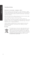
1
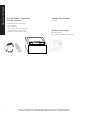
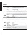
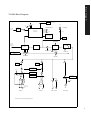
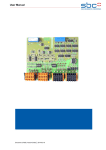
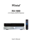
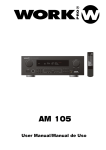
User’s Manual
TX-300V Studio Transmitter
Phonak Communications AG
Laenggasse 17
3280 Murten
Switzerland
T +41 (0) 26 672 96 72
F +41 (0) 26 672 96 77
[email protected]
www.phonakcom.ch
Welcome to Phonak
TX-300V Studio Transmitter
Package Contents
•
•
•
•
•
•
i
TX-300V Studio Transmitter
Power Supply
User’s Manual
Telescoping Antenna Radials (2)
Antenna Mounting Assembly
50 Ohm Coaxial Cable (7.6m)
Phonak Part Number
116-1938
Optional Accessories
Rack Mount Kit
(part number 116-1940, see page 14)
Phonak™ and the Phonak Logo are registered trademarks of Phonak Communications AG.
TX-300V_2006_01_20 © 2006 Phonak Communications AG. All Rights Reserved.
Specifications. . . . . . . . . . . . . . . . . . . . . . . . . . . . . . . . . . . . . . . . . . . . . . . . . . . . . . . 4
Block Diagram . . . . . . . . . . . . . . . . . . . . . . . . . . . . . . . . . . . . . . . . . . . . . . . . . . . . . . 5
Quick Reference . . . . . . . . . . . . . . . . . . . . . . . . . . . . . . . . . . . . . . . . . . . . . . . . . . . . 6
Setup Instructions . . . . . . . . . . . . . . . . . . . . . . . . . . . . . . . . . . . . . . . . . . . . . . . . . . . 7
Operating Instructions. . . . . . . . . . . . . . . . . . . . . . . . . . . . . . . . . . . . . . . . . . . . . . . . 9
Audio Control . . . . . . . . . . . . . . . . . . . . . . . . . . . . . . . . . . . . . . . . . . . . . . . . . . . . . . 9
RF Reception Maximization Strategies. . . . . . . . . . . . . . . . . . . . . . . . . . . . . . . . . . 10
Troubleshooting. . . . . . . . . . . . . . . . . . . . . . . . . . . . . . . . . . . . . . . . . . . . . . . . . . . . 11
Compliance Notice . . . . . . . . . . . . . . . . . . . . . . . . . . . . . . . . . . . . . . . . . . . . . . . . . 12
Warranty . . . . . . . . . . . . . . . . . . . . . . . . . . . . . . . . . . . . . . . . . . . . . . . . . . . . . . . . . 13
Optional Accessories . . . . . . . . . . . . . . . . . . . . . . . . . . . . . . . . . . . . . . . . . . . . . . . . 14
Table of Contents
Table of Contents
Specifications
Specifications
RF
Audio
Controls
Indicators
Power
Physical
Environmental
4
Frequency Accuracy
/-.005% stability 0 to 50C
Transmitter Stability
50 PPM
Output Power
50mW, 100mW, 300mW (Actual power for each frequency set by Phonak)
Antenna
Dipole Antenna (Included with Transmitter)
Antenna Connector
BNC
Compliance
FCC Part 15, Industry Canada, RoHS
System Distortion
<2% total harmonic distortion (THD) at 80% deviation
Audio Input 1
Rear panel. Female-XLR and phone combo connector, balanced. 0/-55 dBu (line/mic)
nominal input level adjustable
Audio Input 2
Rear panel, (2) Phono connectors, unbalanced, -10/+10 dBu nominal input level adjustable,
+30 dBu maximum, impedance 100k ohms
Combined Audio Output (Mix)
Rear panel, (2) Phono connectors, unbalanced, 0 dBu nominal output level, +19 dBu maximum, impedance 10 ohms
Headphone Output
Front panel, (1) 3.5 mm connector, unbalanced, adjustable output level
Front Panel
Power, Test Tone on/off, Channel up/down, Input Level, Mix Level, Contour, Headset Level
Rear Panel
Input 1 Level (Line, Mic, Mic-Phantom Power), Input 2 Level (-10/+10 dBu), RF Power (low,
mid, high)
Internal Adjustments
Compression ratio for audio processor
Programming
Processing on/off
Input 1 and Input 2, Mix VU Meters
8 Green, 2 Red
Processing
Indicated by a green LED when on
RF Power
Indicated on the LCD Display
Power
Red LED illuminates when the unit is powered up
LCD Display
Channel designation, lock status, RF Power Level, programming
Test Tone
Red LED illuminates when test tone enabled
Power Supply Type
In-line power supply
Power Supply Input
115/230VAC, 50/60Hz
Power Supply Output
12VDC, 1.3 A
Power Supply Connector
5.0 mm (.02 in) 2.5 mm (OD x .01 in) ID, barrel type
Compliance
CE, UL
Dimensions W x D x H
20.3 x 20 x 4.45 cm (8.0 x 8.0 x 1.75 in)
Unit Weight
1.4 kg (3.0 lbs)
Unit Weight with Power Supply
2.0 kg (4.4 lbs)
Shipping Weight
2 kg (5.0 lbs)
Rack Mounting
½ rack unit, optional rack mount not included. Order Phonak part number 116-1940
Temperature - Operation
&)WRÝ)
Temperature - Storage
&)WRÝ)
Humidity
0 to 95% relative humidity, non-condensing
Block Diagram
TX-300V Block Diagram
POWER
On
RS-232
DB-9 Connector
Programming
3.5MM
Off
Red
LED
115/230VAC
50/60 Hz
CHANNELSELECT
Universal
Power Supply
(included)
MONITOR
Up
12VDC, 1.3A
Power Supply
CPU Module
Volume
Down
Phonak LCD Display
MIX Level
VU Meter
Compression Ratio
(internal adjustment)
Remote
Antenna
(included)
Pre-emphasis
Transmitter RF
Modulation
Processing
ANTENNA
MIX LEVEL
Low
Functions controlled by the
CPU Module
Mid
Green
LED
On
High
RF POWER
CONTOUR
Off
PROCESS
Input 1 VU
Meter
Input 2 VU
Meter
Input Level POT
Front Panel
12VDC
Input 1 Level Select
Line, Mic, Mic-Phantom Pwr
Mic
Line
Mic
Phantom Pwr
Input 2 Level Select
-10dBu, +10dBu
+10dBu
Test Tone Button
Front Panel
-10dBu
ON
OFF
Red
LED
Female XLR - ¼“
Combo Connector
2/Tip
3/Ring
Phone
Phone
400Hz
1/Sleeve
INPUT 1
INPUT 2
MIX OUTPUT
TEST TONE
All switches are shown in their default positions.
5
Quick Reference
Quick Reference
TX-300V Front Panel: Controls & Displays
Indicates
Process Mode
is active
Adjust audio input levels
of Input 1 and Input 2
here. See page 9 for more
information
Power
ON / OFF
Test Tone:
Activates a tone to
aid system setup
Indicates audio input
level of Input 1 and
Input 2
LCD: Shows
which channel
is selected
Shows mixed
audio level
Mix Level: Adjust so
the Mix Level meter
occasionally lights
the red LED
Contour: Equalization
adjustment. Turn counterclockwise for voice and
clockwise for music
Channel Select Up:
Press for 3 seconds
to lock on current
channel
Monitor Port:
Plug in a headset
and adjust volume
Channel Select Down:
Press for 8 seconds to
enter program mode.
See page 9 for more
information
TX-300V Back Panel: Connections & Settings
Remote Antenna Connection:
See page 8 for details on
antennas that can be attached
here
Mix Output: These connectors
contain a mix of Input 1 and
Input 2. They are unbalanced
phono connectors; and the
output level is -10dBu
Input 2: Set switch to
match the level of your
Input 2 audio source.
Input 1: Used for balanced
connection of a microphone or
line level input. This combination
connector accepts either XLR or
phone connectors
Serial Port:
Used for programming
Set RF Power level here (¼ , ½
and Full). See page 7 for guidelines on setting power levels
6
The power supply
connects here
Input 2: Connect unbalanced
audio to these phono connectors, input level -10dBu or
+10dBu
Select Line, Mic or Mic+Phantom
Power. Line is balanced 0
dBu input level, Mic is -55dBu,
+12VDC supplied in PH PWR
position. If not using input 1, leave
in line position.
Setup
TX-300V Studio Setup Instructions
Unpack the Product
Remove outer packaging and plastic cover. Inspect for
physical damage.
Mount in Rack (if necessary)
If rack mounting the unit, install the optional rack
mount kit (part 116-1940) according to the instructions
included with the kit, then install the TX-300V in the
rack.
Input 1
Connect the audio source(s) to one or both audio input
connections. Input 1 offers a choice of a balanced XLR
or phone connector.
Back of TX-300V with XLR connected to
Input 1
Line
Mic
Rack Mount with dual unit installed
Rack Mount with single unit installed
Connect Power
Plug the power supply into the power connector on the
back panel, then plug the power supply into an outlet.
Plug your microphone into Input 1 and move the input
select switch to Mic (for dynamic microphones) or Mic
+ PH Power (for condenser microphones).
XLR Wiring
Use only the original power supply:
- AC Adaptor, Input: 115/230VAC,
50/60Hz and Output: 120VDC, 1.3A,
Model SP48-151000A
Set RF Power
Set the RF POWER switch on the back of the unit to
Full, ½ or ¼ (Level is indicated on the LCD display).
The amount of transmitted RF power that you will need
depends on your application. If you are operating multiple transmitters in the same environment, it is best to
set the transmitter’s output power to its lowest level to
reduce the possibility of interference.
Full Power
Mic with
Phantom
Power
1/2 Power
Phone Wiring
- +
1/4 Power
Connect Audio Inputs
The TX-300V has two audio input options: Input 1
and Input 2. Input 1 is a balanced connection using
either an XLR or phono connector. Input 2 has two
unbalanced mixing phono connectors. Use Input 1 if
you are using a microphone or if you have a balanced
connection such as from a professional audio mixer (you
can also use Input 1 for unbalanced connections). Use
Input 2 to connect to an unbalanced audio source.
Input 2
Plug your unbalanced audio source into Input 2 and
select the audio level switch for -10dBu or +10dBu, to
match the audio level coming from your equipment.
7
Setup continued
TX-300V Setup Instructions continued
Antenna Installation
Your TX-300V Studio Transmitter Set includes a remote antenna that
features two adjustable-length radials. Extending these radials to the
correct length is extremely important for the system to achieve maximum
transmission range.
Use the following process to determine how long to set your antenna radial
lengths:
1) Determine the average of the highest and lowest frequencies you will
use with this transmitter. (Example: If you are going to use 182.50 MHz
and 186.250 MHz then take the average of 182.50 +186.250 and then
divide by 2=184.375MHz).
2) Divide 7500 by the average frequency (in MHz), then subtract 5 from
this result. The solution to this equation is the length in centimeters to set
your radials to. (Example: 7500/184.375=40.68. 40.68-5= 35.68cm radial
length).
3) Extend the two adjustable length radials to the calculated length
(Example: 40.68 centimeters). Screw the two radials to the antenna
mounting assembly.
4) Install the antenna mounting assembly in desired location, preferably
high on a wall, away from any metal objects and with minimal obstuctions
between antenna and location of receivers and orient ground side downward as indicated on the plastic housing.
5) Connect the RG 58, 50 Ohm coaxial cable to the BNC connectors on
the antenna and on the transmitter.
8
TX-300V Operation
TX-300V Operating Instructions
Power Unit On
Turn power on by pressing the power button.
Select a Channel
Select the transmit channel by pressing the channel
select UP and DOWN buttons.
Channel Select
UP and DOWN buttons
Lock on Channel
Once you determine your transmit channel, you can
lock the transmitter on that channel. To lock a
channel, hold the Channel Select
“Up” button for 3 seconds until
the padlock icon appears on the
display. To unlock,
repeat this process and the padlock icon will disappear.
Test Tone (if necessary)
To broadcast a test tone, press the test tone button.
This helps to test receivers when no audio source is
available.
Press Test Tone
button here
TX-300V Audio Control
Adjust Audio Input Level
Adjust the input knob counterclockwise to add gain
to Input 1. This will decrease gain to Input 2. Adjust
input knob clockwise to add gain to Input 2. This will
decrease gain to Input 1. If you have two audio sources
connected to both Input 1 and 2, adjust the level of
one input using the VU meter, then adjust the output
level of the other audio source. Adjust the input level
until the left VU meter(s) occasionally illuminate the
red LEDs. Illumination of the red LEDs indicates the
unit is in limiting. Limiting is required so that the unit
does not over-modulate the transmitter. If you don’t
want any audio limiting to occur, make sure the red
LEDs never illuminate. If
you want a highly limited
signal, turn the audio gain
up so the red LEDs
illuminate often.
Adjust Contour
Adjust the Contour knob counterclockwise if your
audio source is mostly
voice. Adjust the knob
clockwise if your audio
source is mostly music.
The Contour knob adjusts
the relative equalization of
the unit. This equalization
boosts or cuts frequencies above 5 kHz.
Adjust Mix Level
Adjust the mix level until the
right VU meter occasionally
illuminates the red LED. This
is the level adjustment for the
combined output from Input 1
and Input 2.
Process Mode
Process mode is used for Audio Gain Control (AGC).
With the process mode enabled, the TX-300V will
automatically adjust for inconsistent signal input levels
by raising or lowering the signal level accordingly to
provide a consistent sound output level. This feature
should be used in applications where a consistent
sound level is important and the input levels vary
substantially. Typically you would not want to engage
the Process Mode when a speaker’s emphasis is critical
to the message they are conveying.
Your TX-300V has been shipped to you with process
mode enabled. To enable or disable process mode hold
the channel select “Down” button for 8 seconds while
the unit is on. After 8 seconds the
unit will go into program mode
and the program (PGM) icon will PGM
appear on the LCD.
Once in the program mode, the Process feature can be
toggled on and off by pressing the channel select “Up”
button.
LED lit when Process
is enabled
9
RF Reception
RF Reception Maximization Strategies
For proper and dependable operation, Phonak receivers need to receive a
strong and consistent signal from the originating transmitter. The following
strategies should be used to maximize this signal:
1. When designing and installing your system, keep in mind that the
location of the transmitting antenna is critical to maximize broadcast range.
2. Eliminate or minimize obstructions between the transmitter and
receiver(s).
3. Minimize the distance between the transmitter and receiver(s).
4. Move the transmitting antenna away from metal or conductive objects.
5. Place the transmitting antenna as high as possible.
6. Orient the transmitting antenna vertically.
7. Position the RF Power switch on the back of the TX-300V to full RF
Power, unless lower power is necessary (see page 7).
8. Extend radials to the correct length for selected frequencies (see page 8).
CAUTION: When installing antennas, ensure the antenna is clear of power
lines.
10
Troubleshooting
TX-300V Troubleshooting
The TX-300V has no power
Make sure the power transformer is connected to a power source and is connected to the jack marked
“Power Input”. Make sure the POWER button is pressed in.
There is no audio or the audio level is too low
Make sure that your audio source is properly connected to Input 1 and/or Input 2. The Input 1 or
Input 2 switches must be in the correct position for the appropriate input level. For example: if you
are using the output of a mixer on Input 2, the switch should be in the -10dBu position. If it were
to be in the +10dBu position, the level would be too low. Also, check the Input knob to ensure it is
properly adjusted. You should be able to see the VU meter deflect on Input 1 or Input 2
corresponding with the input level of the audio source. You can listen to the audio source by
connecting a headset to the front panel jack and adjusting the Monitor volume control.
If the level of audio into the transmitter is low and can’t be corrected using the level input switches,
the audio processor can be turned on to boost the signal (see page 7 to set, page 9 for description of
Process Mode).
The audio is distorted
Check to make sure you have the input level select switches in the proper position. You may be
providing too much audio level for the input stage to handle.
There is hum in the audio
Make sure you have properly grounded the audio source to the TX-300V. Check the connections from
the audio source to the TX-300V. If you can, try to use a balanced audio source - this will reduce the
chance of creating hum. Connect a ground wire from the TX-300V to ground and/or to the ground of
the source audio.
There is a tone
The Test Tone button has been pressed (its LED light is on). Push the Test Tone button to turn off
the tone.
The Audio Input 1 sounds “tinny”
If you are using an unbalanced audio source, make sure Pin 3 on the XLR or the ring on the phone plug
is grounded.
I can pick up the signal on the receiver, but it sounds like it’s not tuned in
Check to make sure the transmitter and receiver are on exactly the same channel. It’s a good idea to
lock the channels once they have been set. To lock theTX-300V, press the UP button for a 3 seconds.
End users are adjusting the unit
First, lock the channel by pressing and holding the channel select UP button for 3 seconds. Consider
removing the Input, Mix Level and Contour knobs. You can order a rack mount kit part number
116-1940 from Phonak which offers a security cover that will limit access to the unit.
11
Compliance Notice
Declaration of Conformity / Compliance Notice
Phonak Communications AG, Laenggasse 17, CH-3280 Murten confirms
that the Studio Transmitter TX-300V corresponds to the standards EN 300
422, EN 300 454, EN 301 489-1/-9 and FCC 47 C.F.R. Part 74, including
all necessary annexes.
Please check with your local Phonak distributor, if you need a license from
your local regulatory agency to operate the system.
This transmitter may only be used to provide auditory assistance to
persons in studio, stage and entertainment settings and persons with hearing
disabilities. Two-way voice communications and all other types of uses not
mentioned above are expressly prohibited.
Caution: Changes or modifications not expressly approved by the party
responsible for compliance could void the user’s authority to operate
Phonak equipment.
Recycling
The symbol with the crossed out disposal bin indicates that
equipment shall not be treated as household waste. Please
hand over your old or unused equipment to the applicable
collection point for the recycling of electrical and electronic
equipment. By ensuring this product is disposed of correctly,
you will help prevent potential negative effects on the
environment and human health.
12
Compliance Notice
Compliance Notice
Warranty
Warranty
Phonak offers you a comprehensive global warranty which becomes
effective on the date of purchase. Please ask your local Phonak
distributor about the details and duration. This warranty covers any repairs
due to defects in material and/or workmanship. The warranty does not
cover damage from improper handling or care, exposure to chemicals,
immersion in water or undue stress. Damage caused by third parties or
non-authorized service centers renders the Phonak warranty null and void.
This warranty does not include any service performed by a local distributor
in their office.
Serial number: _________________________________
Date of purchase:_________________________________
Contacting Phonak
Address:
Phone:
Fax:
Phonak Communications AG
Laenggasse 17
3280 Murten
Switzerland
Web Site:
www.phonakcom.ch
Email:
[email protected]
+41 (0) 26 672 96 72
+41(0) 26 672 96 77
13
Optional Accessory
Rack Mount Kit
116-1940 Rack Mounting Kit
Includes components for single and dual rack configuration and a
security cover
14
Phonak Communications AG
Laenggasse 17
3280 Murten
Switzerland
T +41 (0) 26 672 96 72
F +41 (0) 26 672 96 77
[email protected]
www.phonakcom.ch
16
16