1
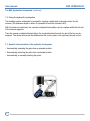
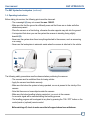
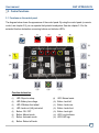
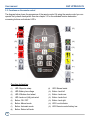
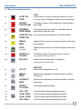
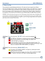
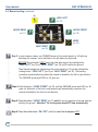
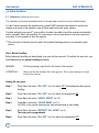
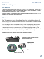
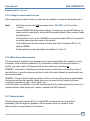
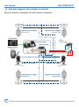
User manual
E&P HYDRAULICS
LEVELSYSTEM
C A R A V A N
HYDRAULIC LEVELSYSTEM
CARAVAN
(6 supports)
ENGLISH
User manual
E&P HYDRAULICS
Copyright © 2014, E&P Hydraulics
This manual is copyrighted, with all rights reserved. Under the copyright laws, this may not, in whole or
in part, be copied, photocopied, reproduced, translated or converted to any electronic medium or
machine readable from without prior written consent of E&P Hydraulics.
Limited Warranty
Under all circumstances this manual should be read thoroughly, before installing and/or using the
product. In no event shall E&P Hydraulics be liable for any direct, indirect, special consequential or
incidental damages arising out of the use or inability to use this documentation or product, even if
advised of the possibility of such damages.
E&P Hydraulics reserves the right to change parts of the device at any time without preceding or direct
announcement to the client.
E&P Hydraulics reserves the right to revise the manual(s), and to make changes in the contents
without obligation to notify any person or entity of the revision or change. A registration number
appears on the product. Make sure that this official registration number has not been removed. It
should be used whenever servicing by E&P Hydraulics or an authorized E&P Hydraulics dealer is
necessary.
Important
This equipment has been tested and found to comply with the limits valid for this device, pursuant to
EN300220, EN301489, EN60950 rules conform 868MHZ. These limits are designed to provide
reasonable protection against harmful interference when this product is operated in a commercial
environment. Any unauthorized changes or modifications to this device could void the user’s authority
to operate this equipment.
For CE-countries:
This device is in conformity with the CE standards. Please note that this device can ONLY be used
with the official E&P Hydraulics level system parts to conform to these standards.
E&P Hydraulics - user manual - caravan - UK vers.- 08-01-15
User manual
E&P HYDRAULICS
Index
Preface
page 4
The E&P Hydraulic levelsystem
1.1 Operating of the levelsystem
1.2 Using the levelsystem
1.3 Specific characteristics of the levelsystem
1.4 Operating instructions
page
page
page
page
Chapter 2
Safety warnings
page 8
Chapter 3
Control functions
3.1 Functions on the control panel
3.2 Functions on the remote control
3.3 Extensive function declaration
page 9
page 10
page 11
Operating the levelsystem
4.1 Automatic levelling
4.2 Manual (by hand) levelling
4.3 Retracting the jacks
page 12
page 13
page 15
Extra functions
5.1 Setting the zero point (calibration)
5.2 Remote control programming (optional)
5.3 Emergency pump (when installed)
page 16
page 17
page 20
Chapter 6
Schematic diagram
page 22
Chapter 7
Remarks and recommendations
page 23
Chapter 8
Troubleshooting (error mode)
page 24
Chapter 9
Maintenance
page 25
Chapter 10
Warranty
page 26
Chapter 11
Notes
page 27
Chapter 1
Chapter 4
Chapter 5
5
6
6
7
3
User manual
E&P HYDRAULICS
Preface
With the purchase of the E&P Hydraulics levelsystem your caravan will be automatically levelled and/or
put stable placed with one push of a button.
Never a caravan:
• that moves when you walk through it, or if it is windy.
• which you suffer from unwanted opening or closing doors.
• where the shower water runs through to the wrong side caused by height differences.
• wherein you have the problem of sleeping in a lean angle.
All issues that are fixed with the E&P Hydraulics levelsystem.
The ergonomic design ensures effortless handling and the sympathetic good looks will automatically
enhance your working environment. It is based on proven E&P Hydraulics technology which forms the
basis of all our E&P Hydraulics products. After installation one button operates the entire system.
Within the E&P Hydraulics strategic vision this products is 100% user friendly and reliable.
This philosophy does not only apply to our customers (end users). Also the technicians installing this
device/system at the dealers are very important to us. This product greatly depends on a proper,
professional installation. That’s the reason why E&P Hydraulics do all they can do to support the
people who are responsible for installing our products for you.
This manual is part of our policy. In this manual we explain how to use the general characteristics as
easy and efficient as possible.Precisely follow these instructions for the installation, because installing
the E&P Hydraulics levelsystem is a precise job. Fully installing the system requires a high level of skill.
After all, we are dealing with equipment that must be able to withstand huge forces, something that is
often underrated by people with insufficient technical training. If the installation is not performed
correctly, serious damages could result in a short time, and even personal injury. Therefore this system
may only be installed by professional technicians with sufficient practical experience and a thorough
relevant technical training. At all times, the installer will bear sole responsibility for the assembly of the
system.
This product is based on hundreds of test hours as well as many successful installations. If you follow
this manual step-by-step, you will see what a wonderful, user friendly, quality product this is. However
there will always be aspects that can be improved. If you have any suggestions, remarks or questions
concerning this product or manual, please do not hesitate to contact us.
On behalf of E&P Hydraulics,
Eric Klinkenberg & Pierre Blom
4
User manual
E&P HYDRAULICS
1. The E&P Hydraulics levelsystem
1.1 Operating of the levelsystem
The E&P Hydraulics levelling system is an electrically/hydraulically driven system.
A hydraulic pump is powered by a 12V direct current motor, which will pump hydraulic oil through a
system of hydraulic hoses two hydraulic axle-supports and four hydraulic corner-supports, with the aim
of stabilizing and levelling the caravan. Mounted to this pump are the oil reservoir, the valve block and
solenoid (magnetic) valves.
The E&P Hydraulics levelsystem is electronically controlled by an operating system or so called mainunit, which is mounted at a central location in the caravan.
The levelsystem can be operated either fully automatically or manually by means of a built-in control
panel and/or (optional) remote control. Most frequently the control panel is mounted in the sidewall at
the entrance of the caravan.
The jacks have the weight bearing and levelling capacity your caravan requires. Each axle-support has
a 180 mm. foot plate on a flexible pivot, guaranteeing the greatest firmness possible on any surface.
B.
A.
A. Axle-supports (2 pcs)
B. Corner-supports (4 pcs)
C. Control panel
D.
C.
F.
E. Protective casing (pump housing)
E.
G.
D. Remote control (optional)
F. Hydraulic pump
G. Operating system (main-unit)
5
User manual
E&P HYDRAULICS
The E&P Hydraulics levelsystem (continued)
1.2 Using the hydraulic levelsystem
The levelling system is designed to be used for creating a stable and horizontal position for the
caravan. (the maximum slope on which it is possible to level the caravan is 8%).
With the electronic spirit-level, the caravan is adjusted horizontally over its complete width with the aid
of the two axle supports.
Then the caravan is adjusted horizontally in the longitudinal direction with the aid of the four corner
supports. The whole caravan will be stabilized via the control panel or the (optional) remote control.
1.3 Specific characteristics of the hydraulic levelsystem
• Automatically extending the jacks from a retracted position.
• Automatically retracting the jacks from a extended position.
• Automatically or manually levelling the jacks.
6
User manual
E&P HYDRAULICS
The E&P Hydraulics levelsystem (continued)
1.4 Operating instructions
Before taking into service, the following points must be observed:
• The noseweight (A) may not exceed the max. 100 KG.
• Make sure the that the ground is sufficiently even and that there are no holes and/other
obstuctions present.
• Place the caravan on a firm footing, otherwise the axle supports may sink into the ground.
• It is important that when you use the system the caravan is standing facing slightly
downhill (B).
• Never use the system when there is anything attached to the caravan, such as an awning
or a canopy.
• Never use the levelsystem in automatic mode when the caravan is attached to the vehicle.
A.
B.
Max. 100 KG
The following safety precautions must be observed when positioning the caravan:
• The caravan must be unhitched from its towing vehicle.
• Apply the caravan hand-brake securely.
• Make sure that when the system is being operated, no-one is present in the vicinity of the
caravan.
• Note that there are no loose objects under the caravan.
• Make sure that when levelling is being carried out, no-one is in the caravan.
• An acoustic signal will be sounded during the levelling process.
• The levelling program cab be stopped at any time by pressing the “ON / OFF” button on the
control panel or (optional) remote control.
Before driving off, check to make sure that all supports have been withdrawn.
7
User manual
E&P HYDRAULICS
2. Safety warnings
Fail we to observe the following warnings may lead to damage to the caravan and/or serious physical
injuries.
• Using the E&P Hydraulics levelling system for other purposes than supporting the caravan is officially
forbidden according to E&P Hydraulics limited warranty.
• This product is exclusively developed as a levelling system and is not designed to be used for other
work underneath the caravan. If the system is utilised to help with changing a wheel, it is the
responsibility of the user to ensure the caravan is secured safely in position. Never lie underneath a
jacked-up vehicle, as this is dangerous and could result in serious injury! Please always refer to your
caravan manufacturer’s recommended jacking procedures.
• When the system is operating, all persons and animals should keep their distance.
• Body parts (e.g. hands and eyes) should never come into contact with released fluids. Oil leaving the
hydraulic levelling system may be under high pressure and could cause serious injuries to the skin.
Consult a doctor immediately in case of accident.
• The caravan should be parked on a solid, non-slippery surface. The parking location must
be free of holes and free of waste and surrounding objects.
• If the caravan is parked on very soft soil, you must place a support plate under each jack in order to
distribute the weight.
• Check that the installation of the hydraulic levelsystem is performed by a skilled mechanic with
sufficient practical experience and technical E&P Hydraulics training.
• In case of repairs/malfunctions to the hydraulic levelsystem: know what you are doing. Never try to
repair it yourself, but consult your installer or dealer.
• Fully read this user manual before using the hydraulic levelsystem.
• After deploying the hydraulic levelsystem ALWAYS make an inspection tour around the caravan, just
to be sure the caravan stands stable (all hydraulic jacks are on the ground).
8
User manual
E&P HYDRAULICS
3. Control functions
3.1 Functions on the control panel
The diagram below shows the appearance of the control panel. By using the control panel (or remote
control, see chapter 3.2) you can operate the hydraulic levelsystem. See also chapter 3.3 for the
extended function declaration concerning buttons and indicator LED’s.
(16)
(1)
(2)
(3)
(4)
(5)
(9)
(6)
(10)
(7)
(11)
(8)
(13)
(12)
(14)
Function declaration:
(7)
LED: Slope too steep
LED: Battery low voltage
LED: Withdraw front wheel
LED: Jacks not (fully) retracted
Button: ON / OFF
Button: Manual mode
Button: Automatic mode
(8)
Button: Retract all Jacks
(1)
(2)
(3)
(4)
(5)
(6)
(9)
(10)
(11)
(12)
(13)
(14)
(16)
LED: Manual mode
Button: Jack left
Button: Jacks rear
Button: Jacks front
Button: Jack right
LED: Level indicator
LED: E&P logo
9
User manual
E&P HYDRAULICS
3.2 Functions on the remote control
The diagram below shows the appearance of the remote control. By using the remote control you can
operate the hydraulic levelsystem. See also chapter 3.3 for the extended function declaration
concerning buttons and indicator LED’s.
(1)
(12)
(3)
(10)
(14)
(2)
(13)
(15)
(4)
(5)
(9)
(7)
(11)
(6)
(8)
Function declaration:
(1)
(2)
(3)
(4)
(5)
(6)
(7)
(8)
10
LED: Slope too steep
LED: Battery low voltage
LED: Withdraw front wheel
LED: Jacks not (fully) retracted
Button: ON / OFF
Button: Manual mode
Button: Automatic mode
Button: Retract all Jacks
(9)
(10)
(11)
(12)
(13)
(14)
(15)
LED: Manual mode
Button: Jack left
Button: Jacks rear
Button: Jacks front
Button: Jack right
LED: Level indicator
LED: Remote control battery low
User manual
E&P HYDRAULICS
3.3 Extensive function declaration
(1)
SLOPE TOO
STEEP
LED’s
In this position the caravan cannot be levelled. (the surface
is not even enough) If necessary switch over to manual mode.
(2)
BATTERY
LOW VOLTAGE
The battery is empty or the voltage is too low to be able to
work safely.
(3)
WITHDRAW
FRONT WHEEL
The caravan is too high at the front, withdrawn the frontwheel and the LED will go out.
(4)
JACKS NOT (fully) One or more jacks are extended or not fully retracted.
RETRACTED
(9)
MANUAL
MODE
Indicates that the caravan can now be brought to the correct
level manually.
(14)
LEVEL
Indicates that the caravan can now be brought to the correct
level.
(zero point)
(15)
(16)
BATTERY 9V
VOLTAGE
The battery voltage of the remote control is too low.
E&P LOGO
Indicates that the levelsystem is switched on.
(only present on the remote control)
(only present on the control panel)
(5)
ON / OFF
BUTTONS
Switches the levelsystem on or off.
(6)
MANUAL
MODE
Switches the levelsystem into manual mode for levelling
the caravan.
(7)
AUTOMATIC
MODE
Switches the levelsystem into automatic mode for levelling
the caravan.
(8)
RETRACT
ALL JACKS
Automatically retracts all jacks.
(10)
JACK LEFT
JACKS REAR
JACKS FRONT
JACK RIGHT
Controls retracting and extending the left jack.
Controls retracting and extending the rear jacks.
Controls retracting and extending the front jacks.
Controls retracting and extending the right jack.
(11)
(12)
(13)
11
User manual
E&P HYDRAULICS
4. Operating the levelsystem
4.1 Automatic levelling
The procedure for automatic deployment/extension of the axle and corner supports is as follows.
(1)
(2)
(3)
ON/ OFF
(no. 5)
AUTOMATIC MODE
(no. 7)
Step 1 Press 1x on the button “ON / OFF” (no.5) to switch the levelsystem ON.
The “E&P-logo” LED lights up, indicating that the levelsystem is switched on.
When there is insufficient or no battery voltage, the indicator LED
‘’LOW VOLTAGE’’ (no.2) lights up.
In automatic levelling, the caravan must be tilted a few degrees forwards. The
system will indicate whether you have positioned the caravan level enough. If you
have not, the indicator LED “FRONT WHEEL” (no.3) lights up, and the system
cannot be started automatically. The front wheel must be wound down.
When the caravan leans too steeply, the indicator LED ‘’SLOPE TOO STEEP’’
(no.1) lights up.
REMARK: When the caravan leans too steeply, the caravan cannot be auto matically levelled. You now have two options: Stop the levelling procedure and
place the caravan on a flatter surface and start again with automatic levelling
procedure. Or go further with manual levelling procedure.
Step 2 Press 1x on the button “AUTOMATIC MODE” (no.7) to start the automatic
levelling procedure.
When the levelling procedure is complete, the indicator LED “LEVEL” (no.14)
lights up GREEN.
REMARK: Depending on the angle of the terrain and type of caravan, the
automatic levelling procedure takes about 1 minute.
Step 3 Press 1x on the button “ON / OFF” (no.5) to switch the levelsystem OFF.
12
User manual
E&P HYDRAULICS
4.2 Manual levelling
The procedure for manual deployment/extension of the axle and corner supports is as follows:
The manual levelling function is mainly used when automatic levelling is not possible due to a large tilt
of the caravan. With the help of this feature it is also possible to change the position of the caravan;
think of your sleeping comfort. Most people prefer to sleep with their head up slightly. Depending on
the orientation of the caravan with this feature you can manually adjust the angle where necessary.
REMARK: On the side where the caravan is low, fill the space under the axle support (footplate) with
some boards to compensate the difference in height. This will avoid the risk it is not possible to level
the caravan due to a too large difference in height. In case of too large height difference the hydraulic
jacks may come to the end of their stroke.
(9)
(1)
(2)
(3)
ON / OFF
(no.5)
MANUAL MODE
(no.6)
Step 1 Press 1x on the button “ON / OFF” (no.5) to switch the levelsystem ON.
The “E&P-logo” LED lights up, indicating that the levelsystem is switched on.
When there is insufficient or no battery voltage, the indicator LED
‘’LOW VOLTAGE’’ (no.2) lights up.
In manual levelling, the caravan must be tilted a few degrees forwards. The
system will indicate whether you have positioned the caravan level enough. If you
have not, the indicator LED “FRONT WHEEL” (no.3) lights up.
Step 2 Press 1x on the button “MANUAL MODE” (no.6).
The indicator LED ‘’MANUAL MODE’’ (no.9) lights up, indicating the manual
levelling procedure may begin.
When the caravan leans too steeply, the indicator LED ‘’SLOPE TOO STEEP’’
(no.1) lights up, although this LED lights up, you are able to level.
13
User manual
E&P HYDRAULICS
4.2 Manual levelling (continued)
(9)
JACK LEFT
(no.10)
JACKS REAR
(no.11)
JACKS FRONT
(no.12)
LEVEL
(no.14)
JACK RIGHT
(no.13)
Step 3 In most common cases, one ORANGE arrow on the control panel (no.14) lights up
indicating the caravan has to be lifted on the left side or the right side.
BEFORE lifting this side: FIRST lower the other axle-support by holding button
“JACK LEFT” (no.10) or “JACK RIGHT” (no.13) until it touches the ground.
Then the axle-support as indicated on the control panel (no.14) can be extended by
holding button “JACK LEFT” (no.10) or “JACK RIGHT” (no.13). The levelling
procedure automatically stops when the caravan is levelled in the left to right direction.
The ORANGE arrow level LED (no.14) goes out.
Step 4 Hold the button “JACKS FRONT” (no.12), until the ORANGE arrow level LED (no.14)
goes out. Extention of the front corner supports will automatically stop when the
caravan is levelled in the front to rear direction.
Step 5 Press the button “JACKS REAR” (no.11) until the corner supports at the rear side are
touching the ground. Attention! The level system does NOT stop automatically.
Step 6 Press 1x on the button “ON / OFF” (no.5) to switch the levelsystem OFF.
14
User manual
E&P HYDRAULICS
4.3 Retracting the jacks
Follow the procedure below to retract the axle and corner supports.
(4)
ON / OFF
(no.5)
RETRACT ALL
JACKS (no.8)
Step 1 Press 1x on the button “ON / OFF” (no.5) to switch the levelsystem ON.
The “E&P-logo” LED lights up, indicating that the levelsystem is switched on.
Step 2 Press 1x on the button “RETRACT ALL JACKS” (no.8).
The indicator LED ‘’JACKS NOT FULLY RETRACTED’’ (no. 4) goes out
when all jacks have been fully retracted.
Step 3 Press 1x on the button “ON / OFF” (no.5) to switch the levelsystem OFF.
IMPORTANT: Before departure ensure all supports have been retracted.
15
User manual
E&P HYDRAULICS
5. Extra functions
5.1 Calibration (setting the zero point)
The calibration procedure described below has already been carried out at your dealer/installer.
You don’t have to perform this procedure by yourself. E&P Hydraulics has decided to include this
chapter as an extra in this manual in case of failure and/or service & repair matters.
Consider setting the zero point** as a condition to make it possible to level the caravan automaticallyand/or manually. When this operation, for some reason, has not been done or has been carried out
incorrectly, it is not possible to level the caravan.
** The zero point is the point (level) to which the hydraulic leveling system (in an automatic cycle)
returns.
Start: Manual levelling
Before automatic levelling can be activated, you must set the zero point. For setting the zero point, you
must first perform the manual levelling procedure.
REMARK:
Do this by placing a spirit level in the center of the caravan.
ATTENTION !
Never put the rear brackets first to the ground. This in case creating too much
load on the caravan.
Setting the zero point
Step 1
Press 1x on the button “ON / OFF” (no.5) to switch OFF the levelsystem after manual
levelling.
Step 2
Press 1x on the button “ON / OFF” (no.5) to switch the levelsystem ON.
Step 3
Press 5x on the button “JACKS FRONT” (no.12)
Step 4
Press 5x on the button “JACKS REAR” (no.11)
All LED’s on the control panel light up. (the vehicle stands in zero mode)
Step 5
Press 3x on the button “RETRACT ALL JACKS” (no.8)
The zero point is programmed.
Step 6
Press 1x on the button “ON / OFF” (no.5) to switch the levelsystem OFF.
16
User manual
E&P HYDRAULICS
5.2 Remote control programming
5.2.1 Introduction
The procedure described below has already been carried out at your dealer/installer. You don’t have to
perform this procedure by yourself. E&P Hydraulics has decided to include this chapter as an extra in
this manual, in case of failure and/or service & repair matters.
When this operation, for some reason, has not been done or has been carried out incorrectly, it is not
possible to level the caravan with the remote control.
5.2.2. Antenna
Check if there is an antenna connection on the operating system (see picture below). If this is not the
case, the remote control CANNOT communicate with the hydraulic levelling system. In principle, the
antenna connector and the antenna are always present when you purchase the levelsystem including
a remote control unit.
If you purchased the remote control at a later stage (i.e. not with the levelsystem), then you should
remember that this antenna connection on the operating system (main-unit) could be missing.
The presence of the antenna is dependent on the age of the levelsystem. After January 2013, all
operating systems have this antenna connector. In this case, the dealer/installer can directly connect
the antenna to the operating system (the antenna is supplied with the remote control)
Below is the picture of the operating system including the antenna connection.
Operating system with antenna connection
(built in protective casing)
Operating system
(main-unit)
Antenna
Antenna connection
17
User manual
E&P HYDRAULICS
Remote control (continued)
5.2.3. Battery
Remove the battery-cover on the rear side of the remote control by firmly pressing the cover and then
sliding out. Insert the 9V battery and carefully reassemble the battery-cover (in most cases the battery
is already fitted)
Remote control
Battery 9V
Product CE label
Battery-cover
Registraton label
5.2.4 Programming the remote control (calibrate/pair)
Step 1
In order to pair the remote control to the system, remove the fuse (30Amp.) in the
cable assembly of the hydraulic levelsystem.
Step 2
Press the buttons “AUTOMATIC MODE” (no.7) and “RETRACT ALL JACKS” (no.8)
simultaneously.
When done, the Indicator LED (no.14) with the surrounding 4 arrows starts blinking
GREEN/ORANGE rapidly. This means the remote control is looking for its receiver,
mounted within the operating system.
Step 3
Reconnect the fuse to the system.
- The pairing process should be made within a certain time (apr. 20 sec.)
- The remote control turns off automatically.
- When the Indicator LED (no.14) goes off, the pairing process is complete.
18
User manual
E&P HYDRAULICS
Remote control (continued)
5.2.5 Putting the remote control into use
After programming the remote control you now have the possibility to operate the levelsystem with it.
Step 1
Switch the remote control ON by pressing button “ON / OFF” (no.5) for at least
1 second.
Now the GREEN LED will light up by flashing. As long as you see this LED flashing, the
remote control is searching for contact with the operating system. When contact is made
the flashing stops.
The illumination of one, or two, ORANGE arrows on the indicator LED (no.14) central on
the control panel shows the position of the caravan.
In the unlikely event that the caravan is already level, then the indicator LED (no.14)
lights up GREEN.
Further operation goes as described in the chapters 4.1 up to 4.3
5.2.6 Which device takes command
The device which is switched on first (remote control or control panel) takes the command to control
the system, until that device is switched off. If you would like to switch from one control device to
another, you need to switch off the power from the device that was in operation first.
REMARK 1: In the event of switching over from the remote control to the control panel: you have to
wait a little time, to give the system enough time to switch off contact between the remote control and
the operating system.
REMARK 2: It may be that the operating system is built in such a way that receiving a signal between
the remote control and the operating system works poorly or even not at all (caused by caravan
construction materials e.g. steel, wood, plastics, etc.).
In this case there is a possibility to move the antenna away from the operating system by means of an
optional extension cable (length max. 2 meters, available from E&P Hydraulics).
5.2.7 Battery Indicator
When the battery level indicator LED (no.15) lights RED, the device does not stop working
immediately. After this signal it is possible to use the remote control apr. another 4 times.
Make sure there is a spare battery in the caravan.
19
User manual
E&P HYDRAULICS
5.3 Emergency pump (optional)
5.3.1 Introduction
The optional Emergency hand pump allows the levelsystem to be operated manually, in the
(emergency) event the system is defective, or (more likely) because there is not enough battery
voltage present.
This possibility is offered by E&P Hydraulic for situations where, for whatever reason, the levelsystem
does not withdraw its support jacks and is therefore preventing you from driving, or moving, the
caravan.
We call it an "emergency situation" because in practice the time for withdrawing the hydraulic jacks is,
most often, also the time of a (planned) departure. By not automatically withdrawing the support jacks
you can no longer move, with adverse consequences.
Therefore, E&P Hydraulics offers you the possibility to integrate an emergency hand pump, for the
levelsystem. As the name implies, it is a pump operated by hand that controls (the withdrawal of) all
jacks. This means that the time of your departure, transport or movement can be guaranteed.
The emergency hand pump is mounted under the caravan in such a way that it is accessible from the
side.
Protective pump housing with the
connections to the emergency pump.
20
Emergency hand-pump.
User manual
E&P HYDRAULICS
Emergency pump (continued)
5.3.2 Putting the Emergency pump into use
When actually using the emergency hand pump operation, proceed as follows:
Step 1
Using the Allen key, turn the gold hexagon bolt on the emergency hand pump
clockwise to the right (open position).
Step 2
Place the metal tube (handle) into the black holder on the emergency hand pump
assembly.
Pump (back and forth) with the metal tube until all hydraulic jacks are withdrawn.
(all jacks will be withdrawn at the same time)
The moment you feel pressure (resistance) building up during this movement is the sign
the jacks are fully withdrawn.
Step 3
Remove the metal tube from the holder.
Step 4
Using the Allen key, turn the gold hexagon bolt on the emergency hand pump
assembly carefully, anticlockwise, to the left until it locks (closed position).
.
Attention ! carefully turn to the locked (closed) position
Step 1
Step 4
Gold colored hexagon bolt
carefully open and close
Place the metal tube into the holder
and pump until you start to feel pressure
Step 2 / 3
21
User manual
E&P HYDRAULICS
6. Schematic diagram of the hydraulic levelsystem
Below the schematic view/diagram of the E&P Hydraulics levelsystem.
●
●
Hydraulic corner support
front side: left
Hydraulic corner support
front side: right
Control panel
Battery
(not included)
Operating system
Hydraulic Pump
Remote control
(optional)
●●●●●
-
+
●
●
Hydraulic axle support
left
Hydraulic axle support
right
Hydraulic corner support
rear side: left
Hydraulic corner support
rear side: right
●
●
22
Fuse
User manual
E&P HYDRAULICS
7. Remarks and recommendations
Below is an overview concerning remarks and recommendations (tips) for the hydraulic levelsystem:
• After 4 minutes of no operation, the system will switch off automatically.
• The automatic levelling cycle can only be started after all jacks have been retracted. If the jacks are
not retracted when the automatic cycle starts, the system will do this automatically. So it is not
possible to make short adjustments to the jacks; the system will always first completely retract its
jacks.
• At a low battery voltage, the system will automatically switch off.
• Jacks are extended and you accidentally drive off: the system will immediately give an alarm and the
jacks are automatically retracted as soon as the hand brake is disengaged. In case of vehicles with
a pneumatic brake installation, this takes place when the engine is started.
• All normal functions of the system are switched off, in error mode.
• The jacks always operate 2 at a time at 1 side. The left side, right side, front side and rear side.
Only when retracting do all 4 operate at the same time.
• During winter conditions (e.g. in snow and ice) put something (e.g. a piece of carpet) under the
jacks to avoid sliding.
• Manual operation is mainly recommended for uneven surfaces.
• In manual operation, all four jacks should always be extended before levelling starts.
• The system cannot handle all angles, the limit values differ per caravan.
• If the system makes a slope angle that is too big and no longer responds to requests for automatic
levelling, we recommend bringing the vehicle as close as possible to the zero point in manual mode.
23
User manual
E&P HYDRAULICS
8. Troubleshooting
In case of an error message, check or the caravan stands not too high at the front (front wheel must be
withdrawn), whether the battery has sufficient voltage, whether the oil level is correct, whether there is
any damage to the jacks, and check all the cables.
If this does not lead to a solution for the fault, the fault could be located in the drive units. As the drive
unit does not have any repairable parts, you should contact your E&P Hydraulics dealer/installer.
Under normal circumstances, all LED’s are off and the unit will only respond by pressing the button
“ON / OFF” (no.5) switching the levelsystem on.
Problem
Possible causes
Solution(s)
● The system fails to start **
Battery voltage low.
● Recharge the battery,
Charger is defective or there
is no voltage being supplied.
Oil level to low or no oil in the
system.
● Check for any oil-leaks.
● The red battery lamp lights
up.
● When the red battery lamp
Lights continuously, the
Installation is switched off
for 4 minutes.
● The support jacks do not
extend towards the ground
when the pump is running.
● The system does not work
automatically, lamp front
wheel lights up.
** NOTHING works, even no
LED signal.
The pump is not working
correctly.
Repair or exchange.
There is no or bad electronic
connection.
Check cables for loss of
voltage.
Caravan stands too high on
the front side.
● Withdrawn the front wheel.
Possible cause: the battery is
fully out of order (<5V)
IMPORTANT: For all other reports and/or mal-functioning of the system, please contact your
dealer/installer.
24
User manual
E&P HYDRAULICS
9. Maintenance
The E&P Hydraulics levelsystem does not have parts that need to be maintained periodically. When
parts have been taken apart, the warranty will become invalid. If necessary parts could be substituded,
repaired and/or exchanged (warranty). Please contact your E&P Hydraulics dealer/installer if
necessary.
WARNING: In control/service-works secure the caravan by placing suitable stands under the caravan.
By not doing this you create a real danger of personal injury or serious accident.
Preventative controls
• Periodically checking the hydraulic oil level. (ONLY by dealer/installer)
• The hydraulic oil (type: Pentosin CHF 11S ) preventative replace after apr. 36 months.
• Periodically check the electronic cables and connections.
• Periodically check the hydraulic jacks.
• Remove dirt, sand, mud and other contamination that settles during use, it may obstruct the
operation of the hydraulic leveling system.
• If the jacks remain extended for a longer period of time, the exposed legs should be protected
by spraying them with a silicon lubricant, to help prevent corrosion. If the caravan is located in
a salty environment, this should be done regularly.
• In winter (slippery) conditions we advise you to take additional safety and precautionary measures.
Especially because your safety during operation of the system. For optimal performance under
extreme conditions (- 30 degrees) we recommend the use of a special hydraulic oil for low
temperatures (consult an authorized dealer).
Furthermore, during the winter period we have to deal with situations in which de-icing salt will tack to
the outside of the system. Preventative maintenance should be:
• Good cleaning of the jacks.
• Clean the stainless steel cylinder (piston rod) and spray with a silicone lubricant.
• Remove dirt from the stainless steel foot plate (especially at the bottom, this is the area your
caravan stands on)
• Try to put the caravan in a location as clean and flat as possible.
• Place a piece of rubber (e.g. piece of carpet) between the frozen (slippery) surface and the
the footplate.
• Before leaving make an additional check round the caravan, if necessary remove snow and
ice from the jacks, then you are free to withdraw the jacks.
25
User manual
E&P HYDRAULICS
10. Warranty
Repairs to the caravan must be performed by dealers recognized by E&P Hydraulics. For systems
which are not (or cannot be) changed, installed or repaired by a recognized E&P Hydraulics dealer,
the warranty cannot be used.
E&P Hydraulics gives guarantees for parts of its hydraulic levelsystem against faults in material and
manufacturing for a period of 24 months starting from the date of purchase. If an E&P Hydraulics
product was checked by an official E&P Hydraulics dealer and a fault in material or manufacturing was
discovered within the aforementioned period, E&P Hydraulics is able to choose the following actions:
• Repairing or replacing the faulty part for free in E&P Hydraulics factory or another location
determined by E&P Hydraulics.
• Sending a mechanic to the location where the caravan is at that moment, in order to repair or
replace the product/part on site.
• Writing out a credit note for the defective product/part.
All warranty claims require a product test and approval by (a dealer of) E&P Hydraulics. All repairs
must be approved by E&P Hydraulics before the work starts. There can be no exceptions to this
procedure. Immediately contact E&P Hydraulics directly before trying to perform a repair or change to
your E&P Hydraulics product. Claims for alleged damages to products are only allowed if
E&P Hydraulics has had the opportunity to check the claim.
The warranty becomes invalid when:
If the buyer modifies the system, or if the buyer makes settings independently. In case of abuse or
negligence, overloading, damage through accident, incorrect loading or incorrect weight distribution,
damage through improper use or improper maintenance, connection to wrong parts or repair attempts
by other persons than the acknowledged E&P Hydraulics dealer/installer.
This warranty does not apply to physical damage, damage as a result of force majeure, in case of
commercial use or adaptation of the product or for products that are sold as a special offer
and/or ‘with defects’.
This warranty will become invalid if the product’s identification criteria, which were attached in the
factory, are changed or removed.
26
User manual
E&P HYDRAULICS
11. Notes
27
User manual
E&P HYDRAULICS
E&P Hydraulics NEDERLAND
www.ep-hydraulics.nl
[email protected]
telefoon: + 31 (0) 252 626 151
E&P Hydraulics DEUTSCHLAND
www.ep-hydraulics.de
[email protected]
telefon: + 49 (0) 2274 700 397
E&P Hydraulics UNITED KINGDOM
www.ep-hydraulics.co.uk
[email protected]
phone: + 44 (0)1254 297 785
E&P Hydraulics FRANCE
www.ep-france.com
[email protected]
téléphone: +33 (0) 9 70 40 61 49
E&P Hydraulics NORGE
www.ep-hydraulics.no
[email protected]
telefon: + 47 480 783 78
E&P Hydraulics SVERIGE
www.ep-hydraulics.se
[email protected]
telefon: + 46 (0) 705 640 725
E&P Hydraulics DEALER
LEVELSYSTEM
www.ep-hydraulics.eu
Made in Holland


![MapInfo [v9.5 - v10.0] User manual PDF](http://vs1.manualzilla.com/store/data/005662542_1-c58f11f989f54f88b5c049879cd1b1b4-150x150.png)