1
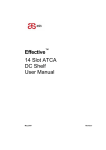
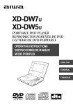
3U 2-Slot ATCA AC/DC Shelf User Manual Proprietary Notice The information contained in this document is proprietary to ASIS Ltd. Use or transfer of this document or the information contained herein without the express written consent of ASIS Ltd. is prohibited. Doc No.: DOC00043 Rev: 2.0 November 2012 Legal Notice and Warranty Information in this document is provided in connection with Asis products. No license, express or implied, by Estoppel or otherwise, to any intellectual property rights is granted by this document. except as provided in Asis terms and conditions of sale for such products, Asis assumes no liability whatsoever, and Asis disclaims any expressed or implied warranty, relating to sale and/or use of Asis products including liability or warranties relating to fitness for a particular purpose, merchant ability, or infringement of any patent, copyright or other intellectual property right. Asis warranty will be for the quality of the shelf for a period of one year after the shipment of the product. Asis may make changes to specifications and product descriptions at any time, without notice. ASIS Ltd. © 2012 Contact Information Asis Headquarters North America Office 27 Shaked St. 11067 Caminito Arcada Industrial Estate - Hevel Modi'im San Diego, CA, 92131USA Shoham 73199, ISRAEL Telephone: Telephone: +972-73-233-6633 Fax: +972-73-233-6634 858 776-1421 E-mail: [email protected] E-mail:[email protected] See the ASIS web site at http://www.asis-pro.com 3U 2 Slot ATCA AC/DC Shelf 2 User Manual Version 2.0 Preface Always keep this manual close to relevant maintenance workstations and reference it prior to and during maintenance activities including any required testing. Applicable Documents For Asis product information and additional resources, please visit the Asis website at www.asis-pro.com. Downloads (manuals, release notes, software, etc.) are available via the Technical Support Library product links at www.asis-pro.com (for registered customers). Information about PICMG (PCI Industrial Computer Manufacturers Group) and the ATCA standard may be accessed on the PICMG Web site at www.picmg.com. Revision History Number Date Comments Author 1.0.1 Jan 2009 Initial release Ilan Bar 1.0.2 Jan 2009 Picture update, power supply to 1500w Ilan Bar 2.0 Nov 2012 rewrite Boaz Bar-Ilan 3U 2 Slot ATCA AC/DC Shelf 3 User Manual Version 2.0 Terms and Acronyms Acronym Meaning ANSI American National Standards Institute ATCA Advanced Telecom Computing Architecture Backplane CE Chassis Passive circuit board providing the connectors for the front boards. Power distribution, management and auxiliary signal connections are supported "Conformité Européenne" ("European Conformity") Enclosure containing subrack, backplane, boards, cooling devices, PEMs. Same as Shelf CFM Cubic Feet per Minute – airflow measurement unit ETSI European Telecommunications Standards Institute FCC Federal Communications Commission FRU Field Replaceable Unit HS Hot swap IPMB Intelligent Platform Management Bus IPMC Intelligent Platform Management Controller IPMI Intelligent Platform Management Interface NEBS Network Equipment Building Systems NRTL Nationally Recognized Testing Laboratories PEM Power Entry Module RTM Rear Transmission Module ShMC Shelf Management Controller, synonymous with Shelf Manager Shelf See Chassis UL Underwriters Laboratories- safety standards 3U 2 Slot ATCA AC/DC Shelf 4 User Manual Version 2.0 Before You Begin Before you begin using this product, or any installation or service operation, please read the following safety information: Attention to these warnings helps prevent personal injuries and damage to the products. It is your responsibility to use the product in an appropriate manner. This product must not be used in any way that may cause personal injury or property damage. You are responsible if the product is used for any intention other than its designated purpose or in disregard of Asis Ltd. instructions. Asis Ltd. shall assume no responsibility for such use of the product. The product is used for its designated purpose if it is used in accordance with its product documentation and within its performance limits. Using the product requires technical skills and a basic knowledge of English. It is therefore essential that only skilled and specialized staff or thoroughly trained personnel withthe required skills be allowed to use the product. Keep the basic safety instructions and the product documentation in a safe place and pass them on to the subsequent users. Applicable local or national safety regulations and rules for the prevention of accidents must be observed in all work performed. 3U 2 Slot ATCA AC/DC Shelf 5 User Manual Version 2.0 Tags and Their Meaning The following indicators are used in the product documentation in order to warn the reader about risks and dangers: Indicates a hazardous situation which, if not avoided, will result in death or serious injury. Indicates the possibility of incorrect operation which can result in damage to the product. Indicates a hazardous situation involving electricity which, if not avoided, can result in death or serious injury. Indicates a hazardous situation involving Electrostatic Discharge (ESD) which, if not avoided, can result in damage to the product. Indicates that components or equipment are heavy and care should be taken to avoid lifting incorrectly. More than one technician is required to lift and carry this equipment. Incorrect lifting can be dangerous to the personnel lifting and may result in dropping and damaging the components or equipment. Indicates a hazardous situation involving touching a moving fan which, if not avoided, can result in serious injury. Indicates that information related to grounding is provided. Indicates that information related to safety or system proper information is provided. 3U 2 Slot ATCA AC/DC Shelf 6 User Manual Version 2.0 Table of Contents Preface .......................................................................................................... 3 Applicable Documents ................................................................................. 3 Revision History ........................................................................................... 3 Terms and Acronyms ................................................................................... 4 Before You Begin ......................................................................................... 5 Tags and Their Meaning ............................................................................... 6 1 Safety Overview ................................................................................. 10 1.1 Safety Conditions of Acceptability ........................................................................... 10 1.2 General Safety Practices ........................................................................................ 10 2 About the 3U Shelf ............................................................................. 14 2.1 Shelf Components Diagrams .................................................................................. 15 2.1.1 Shelf - Front View .............................................................................................................. 15 2.1.2 Shelf – Back View ............................................................................................................. 16 2.2 Shelf Environmental Requirements ......................................................................... 17 2.3 Shelf's IPMB Interconnection .................................................................................. 18 2.3.1 Shelf's DC Power Distribution ............................................................................................ 19 2.4 Shelf Components ................................................................................................... 20 2.4.1 Card Cage ......................................................................................................................... 20 2.4.2 Backplane ......................................................................................................................... 20 2.4.3 Shelf Manager ................................................................................................................... 23 2.4.4 AC Power Configuration .................................................................................................... 26 2.4.5 DC Power Configuration .................................................................................................... 29 2.4.6 Fan Tray ............................................................................................................................ 30 2.4.7 Air Filter Tray ..................................................................................................................... 32 2.4.8 Blank Panels with Air Baffles ............................................................................................. 32 2.4.9 Shelf ID EEPROM Chips ................................................................................................... 33 2.4.10 Cable Management ........................................................................................................... 34 3 Installing the Shelf ............................................................................. 35 3.1 3.2 3.3 Installation Requirements ........................................................................................ 35 Required Tools ........................................................................................................ 35 Site Planning ........................................................................................................... 36 3U 2 Slot ATCA AC/DC Shelf 7 User Manual Version 2.0 3.3.1 Preventing Electromagnetic Interference ........................................................................... 36 3.3.2 Preparing for Rack Installation ........................................................................................... 37 3.4 3.5 3.6 3.7 3.8 3.9 Checking Package Contents ................................................................................... 38 Installation Overview ............................................................................................... 38 Mounting the Shelf on the Rack .............................................................................. 39 Earthing the Shelf .................................................................................................... 40 ESD Safety Requirements ...................................................................................... 41 Electrical Connections ............................................................................................. 42 3.9.1 Connecting AC Power ....................................................................................................... 43 3.9.2 Connecting DC Power ....................................................................................................... 43 3.10 Inserting Front and Rear Boards ............................................................................. 44 3.11 Shelf Power-Up ....................................................................................................... 44 4 Maintenance ....................................................................................... 45 4.1 4.2 4.3 4.4 Resetting the Shelf .................................................................................................. 45 Front and Rear Board Replacement ....................................................................... 46 Cleaning and Replacing the Air Filter ...................................................................... 46 Replacing the Power Entry Module (PEM) .............................................................. 47 4.4.1 Removing the PEM............................................................................................................ 47 4.4.2 Inserting the PEM .............................................................................................................. 47 4.5 Replacing a Power Supply ...................................................................................... 48 4.5.1 Removing the Power Supply ............................................................................................. 48 4.5.2 Inserting the Power Supply ................................................................................................ 48 4.6 4.7 Cleaning / Replacing the Power Supply Filter ......................................................... 49 Replacing a Shelf Manager Board .......................................................................... 50 4.7.1 Removing a Shelf Manager Board ..................................................................................... 50 4.7.2 Inserting Shelf Manager Board .......................................................................................... 50 4.8 4.9 Replacing the Shelf Manager Board Battery ........................................................... 51 Replacing a Fan Tray .............................................................................................. 52 4.9.1 Removing a Fan Tray ........................................................................................................ 52 4.9.2 Inserting a Fan Tray .......................................................................................................... 52 4.10 Replacing the EEPROM Board ............................................................................... 53 4.10.1 Removing the EEPROM Board ......................................................................................... 53 4.10.2 Inserting the EEPROM Board ............................................................................................ 54 4.11 Periodic Maintenance Summary ............................................................................. 54 3U 2 Slot ATCA AC/DC Shelf 8 User Manual Version 2.0 5 6 Troubleshooting ................................................................................. 55 Regulatory and Certification Information ......................................... 57 6.1 6.2 6.3 Safety Compliance .................................................................................................. 57 EMC Compliance - Class A Compliance ................................................................. 57 Additional Certifications ........................................................................................... 58 7 Technical Specifications.................................................................... 59 3U 2 Slot ATCA AC/DC Shelf 9 User Manual Version 2.0 1 1.1 Safety Overview Safety Conditions of Acceptability This equipment is considered Class I product. This equipment has been evaluated for use in a Pollution Degree 2 environment. This equipment has been evaluated for use in a 50C (122F) ambient temperature (AC Version) and in an 55 C (131F) (DC Version) This equipment was tested in a branch circuit protected by a 20A circuit breaker (AC Version). The mains supply cord set used to connect the equipment to AC supply mains must be of an approved type acceptable by the authorities in the country where the equipment is deployed. Boards/blades installed in the shelf card cage are to be of a separately approved type, provided with basic insulation (input to operator accessible connectors and input to conductive parts). 1.2 The DC Version of this shelf is intended for installation in restricted access locations. General Safety Practices Keep personnel away from live circuits! Only trained personnel may open or remove components, remove equipment covers for internal subassembly, replace components, or any internal adjustment. Only qualified, experienced, authorized electronics service personnel may access the interior of the equipment. In the event of an equipment malfunction, all repairs must be performed either by an Asis technician or by an authorized agent. It is the customer responsibility to report the need for service to Asis or to one of its authorized agents. For service information, contact Asis customer support. Never turn on any equipment when there is evidence of fire, exposure to water, or structural damage. 3U 2 Slot ATCA AC/DC Shelf 10 User Manual Version 2.0 Before handling the product, read the instructions and safety guidelines on the following pages to prevent damage to the product and to ensure your own personal safety. Use extreme caution when installing or removing components. Refer to the installation instructions in this document for precautions and procedures. If you have any questions, please contact ASIS Technical Support. Always follow the procedural instructions for the removal and replacement of components in sequence. Remove all metal jewelry before servicing the system. Metal jewelry may inadvertently be caught on a component and cause an electrical short, which may result in shelf outage and possible physical injury. Never push objects of any kind through openings in the equipment as they may touch dangerous voltage points or short components, resulting in fire or electric shock. Beware Electrical shock hazard! The power supplies produce high voltage and energy hazards, which can cause death or serious injury. In any case do not open the power supply case. Under certain conditions, dangerous voltages may exist even with the power cords are disconnected. Before any attempt to service the device, be sure that the device is electrically isolated. System control, equipment and electronic controllers are connected to hazardous line voltages. When servicing the system, extreme care should be taken to protect against shock. High voltages are present inside the shelf when the unit's power is plugged into an electrical outlet. Turn off system power source, turn off the power supplies and then disconnect the power cord from its source before removing the shelf cover. Turning off the circuit breakers do not remove power to components. Do not connect or disconnect any cables or perform installation, maintenance, or reconfiguration of this shelf during an electrical storm. 3U 2 Slot ATCA AC/DC Shelf 11 User Manual Version 2.0 Caution Risk of explosion if battery is replaced by an incorrect type. Dispose of used batteries according to the instructions. Attention Il y a risqué d'explosion si les batteries remplacée par une batterie de type incorrect. mettre au rebut les batteries usages conformément aux instructions. An earth connection is essential before connecting the power supply. Courant de fuite élevé raccordement à la terre indispensable avant le raccordement au réseau. Caution This unit has more than one power supply cord. Disconnect power supply cords before servicing to avoid electric shock. Attention Cet appareil comporte plus d'un cordon d'alimentation. A afin de prévenir les chocs électriques, de brancher les cordons d'alimentation avant de faire le dépannage main. 3U 2 Slot ATCA AC/DC Shelf 12 User Manual Version 2.0 Many components described in this document can be damaged by Electrostatic Discharge (ESD). Follow the precautions described here and before specific procedures detailed in the document to protect static-sensitive components from ESD-related damage. Static electricity can harm system components. Perform service at an ESD workstation and follow proper ESD procedure to reduce the risk of damage to components. ASIS strongly encourages you to follow proper ESD procedure, which can include wrist straps, when servicing equipment. Take the following steps to prevent damage from Electrostatic Discharge (ESD): When unpacking a static-sensitive component from its shipping carton, do not remove the component’s antistatic packing material until you are ready to install the component in the system. Just before unwrapping the antistatic packaging, be sure you are at an ESD workstation or grounded. This will discharge any static electricity that may have built up in your body. When transporting a sensitive component, first place it in an antistatic container or packaging. Handle all sensitive components at an ESD workstation. If possible, use antistatic floor pads and workbench pads. Handle components and boards with care. Don’t touch the components or contacts on a board. Hold a board by its edges or by its metal mounting bracket. Do not handle or store system boards near strong electrostatic, electromagnetic, magnetic, or radioactive fields. 3U 2 Slot ATCA AC/DC Shelf 13 User Manual Version 2.0 2 About the 3U Shelf The 3U 2-Slot ATCA AC/DC Shelf hosts up to 2 application blades and RTMs in a 3U height chassis. The shelf is 19" rack mounted and complies with the Advanced Telecommunications Computing Architecture – PICMG3.1standard. It is designed to meet NEBS and ETSI standards and is UL and CE certified. The shelf is intended for high availability and high reliability applications such as telecom and internet communications and incorporates Field Replaceable Units (FRUs), thus enabling easy and fast field maintenance with minimum or no downtime. Its backplane has various fabric connectivity optimized for performance at 2.5Gbps and10Gbps per pair (40Gbps per channel), including triplicated mesh. The shelf is evaluated as Information Technology Equipment (ITE) and may be installed in central offices, telecommunication centers, offices, computer rooms, and similar commercial type locations. It incorporates the latest technologies available to reduce its price while maintaining performance and reliability. The shelf offers optional redundancy for power input and management functions and is designed to withstand extreme conditions (to meet rigid Telco requirements). An ASIS cable-holder frame is fitted to both sides of the mounting flanges of the shelf, to allow for neat placement of cables attached to the shelf or any of the components it contains. The shelf is available in AC and DC configurations, 90-240VAC or -48/-60 VDC. It contains redundant hot swappable IPMI v1.5 Shelf Manager boards based on Pigeon Point technology ShMM Sentry 500 and utilizes push cooling. The shelf is available in the following configurations: AC Configurations 3U with 2 power supplies of1500W each DC Configuration 3U with 2 PEMs, each with a rating of -48/-60 VDC 40A 3U 2 Slot ATCA AC/DC Shelf 14 User Manual Version 2.0 Table 1: Shelf Dimensions/Weight Dimension Value Width 448mm (17.637”) (19'' rack mount) Height 133.35mm (5.25“) (3U) Depth 413.4mm (16.275'') Weight Value Assembled shelf 3U AC configuration (including 2power supplies) - 14.4Kg (31.75lbs) (includes two fan trays 3U DC configuration (including 2 PEMs) - 11Kg (25.25lbs) &2 shelf managers) 2.1 Shelf Components Diagrams The key components of the shelf are shown in the diagrams of this section. 2.1.1 Shelf - Front View Figure 1: Shelf Components - AC Configuration – Front View 3U 2 Slot ATCA AC/DC Shelf 15 User Manual Version 2.0 Table 2: Shelf Front Components - AC Configuration # Component Description 1 Mounting flanges Mounting flanges on each side to be fastened to the19-inch rack. 2 Shelf managers Two shelf managers, controlling and managing the shelf. SM no.1 is the lower board and SM no.2 is the upper board. 3 ESD terminal Front ESD wrist strap terminal. 4 Card cage Portion of the shelf that holds the blades that are plugged into the backplane. Mechanically compliant with all aspects of PICMG 3.1. 5 Fan tray Fan tray cools the shelf. 6 Air filter tray Keeps the airflow free of dust and particles. 7 AC power supplies Integral 2x 1500W power supplies (only in AC configuration) 2.1.2 Shelf – Back View Figure 2: Shelf Components – Rear View Table 3: Rear Side Components # Component Description 1 EEPROM chips Two shelf ID EEPROM chips under the left-side rear cover. 2 Grounding point Allows shelf grounding to the rack. 3 ESD terminal Rear ESD wrist strap terminal. 4 Blank panels / PEMs Blank panels in AC configuration and PEMs in DC configuration 5 Backplane Supports up to 2 third-party ATCA-compliant front boards, and the complementary rear transition modules (RTM). 6 Card cage Portion of the shelf that holds the blades that are plugged into the backplane rear side. Mechanically compliant with all aspects 3U 2 Slot ATCA AC/DC Shelf 16 User Manual Version 2.0 # Component Description of PICMG 3.1. 7 2.2 AC inlet panel Supports up to 2 power supplies Shelf Environmental Requirements The typical operation temperature and humidity range for the Asis shelf are detailed in the table below. Table 4: Temperature and Humidity Range Temperature Range for Operation AC configuration: o o o o -5 C to 50 C (23 F to 131 F) DC configuration: o o o o -5 C to 55 C (23 F to 131 F) Relative Humidity Range for Operation 5%-95% non-condensed The standard environment of a computer room has an ambient temperature of 20 to 25 °C (68 to 77 °F) and relative humidity of 30-50% during normal operation. Lower temperatures result in better performance and longer MTBF of the equipment. These temperatures apply to the temperature of the air along the length of the cabinet front door. All cabinets draw in ambient air for cooling from the right side, passing through the air filter and discharge heated exhaust air from the left side. There must be sufficient clearance between the Asis shelf and any other systems that may exhaust warm air to allow sufficient cooling. Proper room cooling is vital for the safe and correct operation of the shelf. The site cooling system must have adequate capacity for cooling the room. The air flow in the room must be so designed to prevent recirculation of hot air. Improper room cooling design can result in “environment overload” air temperature gradients causing reduced reliability, component failure, data loss or system shutdown. 3U 2 Slot ATCA AC/DC Shelf 17 User Manual Version 2.0 2.3 Shelf's IPMB Interconnection Figure 3: Shelf Manager Boards Interconnection Diagram 3U 2 Slot ATCA AC/DC Shelf 18 User Manual Version 2.0 2.3.1 Shelf's DC Power Distribution The diagram below shows the shelf’s PEM power distribution. Figure 4: PEMs Power Distribution 3U 2 Slot ATCA AC/DC Shelf 19 User Manual Version 2.0 2.4 Shelf Components All components are factory-mounted in the shelf. The shelf contains the following components: Card cage and backplane Power supplies – relevant for AC power configurations that include up to two AC power supplies PEMs – relevant for chassis with DC power configurations that include two DC power-entry modules Shelf manager boards – two shelf manager boards EEPROMs - two identical EEPROM chips -contain data about the shelf, such as serial number and manufacturer and about the board’s setup, such as shelf thermal budget and slot population. Fan tray - push air flow. Hot-swappable, provides side to side cooling, and is designed to provide full redundancy cooling to components on the front and rear of the shelf. Air filter tray — Keeps the airflow free of dust and particles. Blank Panels — For air flow management. The front and back framework of the shelf incorporate electrostatic discharge (ESD) points, as defined by PICMG 3.0 R2.0 AdvancedTCA™ standard. 2.4.1 Card Cage The shelf’s card cage consists of: The backplane. Right and left guide rails to hold the front and rear boards that plug into the backplane. The card cage supports up to 2 8U front boards (blades), and 2 8U rear transition module (RTM) boards. 2.4.2 Backplane The AdvancedTCA™ compliant backplane, interfaces with up to 28U third-party ATCA-compliant front boards and the complementary rear RTMs and provides interconnectivity between all of the shelf’s components. There are no active components on the backplane and no removable or serviceable parts. 3U 2 Slot ATCA AC/DC Shelf 20 User Manual Version 2.0 Additional backplane features include: Fabric interface with dual-star or triple-replicated mesh interconnect. The fabric interface grid consisting of eight differential pairs per channel The base interface grid consisting of four differential pairs per channel. Bussed IPMI. Hub connections corresponding to slots 1 and 2. Full compliance with AdvancedTCA™ electrical and mechanical specifications. Dual-star Ethernet signaling environment on the Base interface 10, 100-BASE-T dual star Base Interconnect capability. Update- channel interfaces for active and standby synchronization, and mesh topology handling 10Gbps per differential pair The backplane has two functional zones. 2.4.2.1 Update-Channel Connections The update channels are backplane interfaces between pairs of front boards that operate on a redundant basis. Application software can use the update channel for redundancy interlock, or to provide a direct connection that bypasses the (indirect) fabric interface. The figure below shows the locations of the module slot allocations when viewed from the front. The physical and the logical slot allocations are the same for this shelf. The slots are numbered 1 to 2 from bottom to top. Figure 5 – Slot Allocations 2.4.2.2 Base Interface The base interface is comprised of a single row of signal pins for a total of four signal pairs per base channel. In total, the base interface contains up to2 base channels for a total of 8 possible signal pairs per board/slot. A base channel can be used to support a 10/100/1000 BASE-T port. The base interface channel is detailed in the diagram below. 3U 2 Slot ATCA AC/DC Shelf 21 User Manual Version 2.0 Figure 6: Base Interface Channel 2.4.2.3 Fabric Interface The fabric interface allocates signal pairs differently than the base interface. A fabric channel is comprised of two rows of signal pairs for a total of eight signal pairs per channel. Thus, each connector supports up to five channels available for board to board connectivity. A channel may also be viewed as being comprised of four 2-pair ports. 2.4.2.4 Synchronization Clock Interface The backplane supports a set of synchronization clock buses that can exchange synchronization timing information. This synchronization can be used for system-wide and intersystem synchronization purposes, which are important in some applications, such as those involving synchronous time division multiplex (TDM). Table 5: Synchronization Clock and Update Channel Pin Assignments Row # Interface Px20 Connector Pairs ab 1 Clks 2 Update channel cd ef gh CLK1A+ CLK1A- CLK1B+ CLK1B- CLK2A+ CLK2A- CLK2B+ CLK2B- Tx4(UP)+ Tx4(UP)- Rx4(UP)+ Rx4(UP)- CLK3A+ CLK3A- CLK3B+ CLK3B- &Clks The update channels are routed to adjacent slots. Slot 1 connects to Slot 2. 3U 2 Slot ATCA AC/DC Shelf 22 User Manual Version 2.0 Figure 7: Backplane Layout 2.4.2.5 Extra-Low Voltage (SELV) Circuit Connection SELV is a voltage that does not exceed a peak of 42.4 VAC or 60 VDC. The ports labeled LAN, COM, and USB are SELV circuits. SELV circuits must only be connected to other SELV circuits. 2.4.3 Shelf Manager The shelf manager board controls and manages the shelf. It controls the fans speed, monitor temperatures across the shelf, manage the hot swap insertion and extraction of modules and boards, as well as various additional tasks. For detailed information on the Shelf Manager board, refer to the Asis ATCA Shelf Manager User Manual. Figure 8: Shelf Manager Board The shelf manager board is a field replaceable unit with the following features and functionality: 3U 2 Slot ATCA AC/DC Shelf 23 User Manual Version 2.0 2.4.3.1 Fan tray powering and control – RJ45 serial port LED Alarms display Telco Alarms control and display Hosting of the Pigeon point ShMM500 management module Front Ethernet connection. Rear Ethernet connection Hot swap capability providing 12V to the fan trays Shelf Manager Front Panel The diagram and table below detail the connection ports and LED indicators of the shelf manager panel. Figure 9: Shelf Manager Board – Front Panel Table 6: Shelf Manager Board – Front Panel # Component Description 1 ATCA Extraction latch Used for extraction & insertion of the board from the shelf 2 RST Reset push-button 3 LEDs General, alarm and Application LED indicators 4 ACO Alarm Cutoff push button 5 Serial port Serial RS232 communication, RJ 45 connector 6 ETH port Ethernet communication, RJ-45 connector. The following is indicated by the Ethernet connector LED's: Green – Line activity Yellow – 100Mbs 7 Telco alarm The Telco alarm connector is a mini D-type 15 pin connector 8 Locking captive screw Used for securing the shelf manager board inside the shelf 3U 2 Slot ATCA AC/DC Shelf 24 User Manual Version 2.0 2.4.3.2 LED Indicators The front panel of the shelf manager board features nine LEDs arranged in three groups. General LEDs Alarm LEDs Application-defined LEDs The figure and tables below details these LED indicators. Figure 10: Shelf Manager Board – LEDs Indicators Table 7: LED Functions - General LEDs LED Status Description ACT Green Shelf manager is active Red Shelf manager failure Green blink Shelf manager is inactive Green Local voltage supply on Shelf manager is good OFF Local voltage failure Steady Blue Shelf manager is powering up or ready for extraction Blinking blue Shelf manager hot swap process OFF Shelf manager is operating PWR HS (hot swap) Table 8: LED Functions - Telco Alarm LEDs LED Status Description CRT (Critical) OFF Normal operation Red System alarm event OFF Normal operation Red System alarm event OFF Normal operation Red System alarm event MJR(Major) MNR (Minor) 3U 2 Slot ATCA AC/DC Shelf 25 User Manual Version 2.0 Table 9: LED Functions: Application-Defined LEDs LED Status Description Green / Red As defined by application A B C Boot-up LED Status All LED's light up for about 40 seconds during Shelf manager board boot-up. 2.4.4 AC Power Configuration The AC Power Configuration provides power to the shelf via field replaceable and hot swappable, 90 VAC to 240 VAC, power supplies (PSs). The shelf is equipped with AC power inlets located in the rear of the shelf and each power supply has one power inlet. The power cord(s) is considered the disconnect device to the main AC power. The socket outlets that the AC power cables plug into must be installed near the equipment and must be easily accessible. Each power supply provides the following output power: 1500W in 220VAC 1200W in 110VAC. 3U 2 Slot ATCA AC/DC Shelf 26 User Manual Version 2.0 Figure 11: ATCA Power Supply One power supply is capable of energizing a fully loaded chassis. The number of power supplies needed is calculated based on the actual load of the third-party boards while taking into account redundancy requirements. Table 10: AC Configuration Component Distribution Maximum Number Number of PSU & Input Voltage Maximum Load of Boards and Redundancy (1+1) Range (V) (Boards and RTM) RTMs(1) 2 (1+1) 100-170 1520 W 2 170-240 2120 W 2 (1) Under full load of 300 W-front boards/blades and 20 W-rear boards 2.4.4.1 AC Power Supply Panels The AC power supply panel and its LED indicators are detailed in the figure and tables below. Figure 12: AC Power Supply Panels Table 11: AC Power supply Panels # Component Description 2/6 Locking captive screws Used for securing the PS inside the shelf. 3 Extraction latch Used for extraction & insertion of the PS inside the shelf. 4 LEDs Provides visual Indications regards the PS status, see par 2 .2.6.3. 3U 2 Slot ATCA AC/DC Shelf 27 User Manual Version 2.0 # Component Description 5 Air filter Used for air filtering from solid particulates such as dust. 2.4.4.2 AC Power Supply LED Indicators The AC power supplies include LED indicators and are detailed in the tables below. Table 12: AC Configuration AC Power 3 Power Supplies - LED Indicators LED Status Description AC OK Green / OFF Green indicates AC power supply is OK, OFF indicates AC power supply is OFF DC OK Green / OFF Green indicates DC power supply is OK, OFF indicates DC power supply is OFF H. Swap 2.4.4.3 Steady Blue Power supply is powering up or ready for extraction Blinking blue Power supply hot swap process OFF Power supply is operating AC Power Cable Use a power cord rated for the local voltage, 15/10amps, 2 poles, 3 wires. The connector can be terminated to 14 through 16 AWG (gauge) cord only. UL, CSA, VDE approved. The cable is to contain a female connector IEC 60320 C13 on one end and your standard domestic AC power plug that fits your power AC sockets on the other end. 3U 2 Slot ATCA AC/DC Shelf 28 User Manual Version 2.0 2.4.5 DC Power Configuration The DC power configuration consists of two Power Entry Modules (PEMs), each with a rating of -48/-60 VDC 40A. The PEMs provide EMC power filtering and over-current protection to the shelf. Each PEM is capable of supplying 100% of shelf power and is a field replaceable unit. The two-PEM configuration provides full redundancy and the PEMs are located in the bottom-rear of the shelf. Figure 13: DC Power Entry Module The DC configuration does not come equipped with its own power source. The customer must provide a mains DC distribution system that includes batteries and branch circuit breaker of 40A per PEM. The customer must also provide 2 sets of 2 10AWG wires and appropriate lugs for connecting to the PEMs’ terminal blocks. The PEM’s panel contains switches and LED indicators, depicted in the figure and table below. Figure 14: DC PEM – Front Panel Table 13: PEM – Front Panel # Component Description 1 Locking captive screw Used for securing the PEM inside the shelf. 2 Extraction latch Used for extraction & insertion of the PEM inside the shelf. 3 Screw fastener Screw fastener for plastic protective cover to shield the terminal blocs. 3U 2 Slot ATCA AC/DC Shelf 29 User Manual Version 2.0 # Component Description 4 Terminal blocks VReturn .terminals 5 Terminal blocks -48/60 VDC terminals. Do not remove a PEM while an electrical charge remains in the wiring. Before replacing a PEM, verify that power source is disconnected and isolated. PEM's circuit breaker has only one pole and disconnects only the -48V lead. The RETURN lead is constantly connected. 2.4.6 Fan Tray The hot-swappable fan tray contains four 80x80mm fans that supply air for cooling the chassis and blades. The fan tray connects to the fan board backplane, where it plugs into power and control connectors. The air comes in from the right side and exits through the left side of the shelf. 200W for front board and 20W for RTM per slot is supported. Figure 15: Fan Tray In case of single fan failure, the other fan tray in addition to the remaining fans in the same tray will provide the required cooling to dissipate the heat generated by the occupied slots. If a failure occurs, it is recommended to replace a fan tray as soon as possible. It is recommended to replace a malfunctioning fan tray as soon as possible. 3U 2 Slot ATCA AC/DC Shelf 30 User Manual Version 2.0 Refrain from clogging air input and exhaust during shelf operation. 2.4.6.1 Fan Tray Panel The fan tray panel is detailed in the figure and table below. Figure 16: Fan Tray – Front panel Table 14: Fan Tray – Front panel # Component Description 1 ESD terminal Rear ESD wrist strap terminal. 2 Locking captive screw Used for securing the fan tray inside the shelf. 3 Status LED Each fan tray has an indication LED, which indicates fans functioning status. 4 Handle 2.4.6.2 Enables easy extraction of the fan tray for replacement. Fan Tray LED Indicators The fan tray Status LED has two functions, depicted in the table below. Table 15: Fan Tray Status LED Functions LED Status Description Green Normal operation, fans are functioning properly. Red Failure in at least one of the voltages (-48V_A, -48V_B or 12V or 3.3V) or I²C fault. Blinking Red Fan fault 3U 2 Slot ATCA AC/DC Shelf 31 User Manual Version 2.0 2.4.7 Air Filter Tray A NEBS-GR63-compatible air filter is installed on the shelf. The filter is field-serviceable, and can be extracted for periodic cleaning or replacement. The filter is accessible from the front of the card cage. A shelf-based micro-switch detects the installed filter and reports its presence to the shelf manager. Figure 17: Air Filter Tray The air filter must be cleaned periodically. Cleaning frequency depends on how dusty the chassis environment is. It is recommended that the air filter be washed once every three months. For details on air-filter maintenance, see section. 4 .5.10. 2.4.8 Blank Panels with Air Baffles Compliance with ATCA's temperature specifications requires a steady air flow in the shelf. To insure a steady air flow, either the shelf must be fully populated or a blank filler panel must be installedto fill all front and rear empty slots. 3U 2 Slot ATCA AC/DC Shelf 32 User Manual Version 2.0 Figure 18: Blank Board Panel and Blank RTM Panel Table 16: Blank Board Panel and Blank RTM Panel 2.4.9 # Component Description 1 Blank board panel Blank board front module panels, with air baffle. 2 Blank RTM panel Blank RTM panels, with air baffle. Shelf ID EEPROM Chips There are two hot swappable shelf ID EEPROM chips (1 are shown in the figure below), housed in the rear of the shelf on a small board. The EEPROMs store product and manufacturer information such as shelf serial number, part number, backplane routing assignment, and shelf heat budget. Figure 19: Shelf ID EEPROM chips (rear cover removed) When the shelf manager board boots up, it compares the information stored in the two EEPROMs: 3U 2 Slot ATCA AC/DC Shelf 33 User Manual Version 2.0 If EEPROM data coincides, it is loaded and saved in the shelf manager board and the shelf initializes. In case of a mismatch, the data on the EEPROMs is compared with the last saved configuration in the shelf manager board: If the saved configuration matches one of the EEPROMs it is assumed to be the right one and it is stored in both EEPROMs. If the three configurations are all different, the shelf manager board does not boot up. 2.4.10 Cable Management The shelf incorporates two cable holder frames fitted on the sides of the front of the chassis near the mounting flanges. Figure 20: Cable Holder Frames Table 17: Cable Holder Frames # Version 1 Front upper cable holder frame 2 Rear bottom cable holder frame Cables attached to the cable holders must be allowed to move freely. Insure that a service loop of minimal required length is maintained. 3U 2 Slot ATCA AC/DC Shelf 34 User Manual Version 2.0 3 Installing the Shelf Installing the shelf and preparation for its usage is comprised of some or all of the following tasks: Site planning. Checking package contents. Installation overview. Rack mounting. Inserting the front and rear boards into the shelf. Shelf power-up. Due to the danger of introducing additional hazards, do not install substitute parts or perform any unauthorized modification of the shelf. Before installing the shelf, note which cables are to be needed for equipment and power, and whether they are to be connected in the front or rear of the shelf. 3.1 Installation Requirements The shelf must be installed only in a restricted access area and according to the national electrical codes in your country. For North America, equipment must be installed in accordance to the US National Electrical Code (NEC) Articles 110–6, 110–17, and 110–18, and the Canadian Electrical Code (CEC), Sections 2-202 and 2-308. 3.2 Required Tools To install the shelf in a standard 19" rack, the following tools are required: Standard Philips screwdriver set. Wrench. ESD Wrist Strap. 3U 2 Slot ATCA AC/DC Shelf 35 User Manual Version 2.0 3.3 Site Planning Select a location for the shelf that provides adequate room for operating and servicing. The system is designed to operate in a typical office environment. Choose a site that is: Clean and free of airborne particles (other than normal room dust). Well ventilated and away from sources of heat including direct sunlight. Away from sources of vibration or physical shock. Isolated from strong electromagnetic fields produced by electrical devices. In regions that are susceptible to electrical storms, we recommend you plug your system into a surge suppressor. For AC systems, provide properly grounded wall outlets and branch circuit breaker of 16A for each of the power supplies. For DC systems, provide mains DC distribution system that includes for each PEM an external battery and a branch circuit breaker of 50A. Provided with sufficient space to access and replace the power supply modules, fan tray, front and rear boards. Provided with sufficient space at the front and sides of the cage to enable free airflow to cool the boards and power supplies. Only qualified personnel should be involved with this installation procedure. 3.3.1 Preventing Electromagnetic Interference The shelf emits electromagnetic waves that may interfere with nearby equipment. Conversely, nearby electronic equipment may emit electromagnetic waves that interfere with the shelf. 3U 2 Slot ATCA AC/DC Shelf 36 User Manual Version 2.0 To prevent such interferences: The EMC, EMI, and RFI specifications of the shelf and all nearby equipment should be considered when choosing the placement of the shelf and surrounding equipment. In the shelf and most other equipment, the use of fillers panels in unoccupied slots is necessary to keep the product’s emissions within their specified limits. Do not use blank faceplates in place of fillers. Keep slots populated with active modules directly next to each other and fillers directly adjacent to the outermost active modules. If the shelf experiences unexpected and intermittent data errors, carefully consider the possibility of electromagnetic interference from nearby equipment as a possible source of the problem. 3.3.2 Preparing for Rack Installation The 3U 2-Slot ATCA AC/DC shelf is to be installed in a standard 19" rack. All sides of the shelf must be easily accessible. To maintain proper cooling, the equipment rack must provide sufficient airflow to the front and rear of the shelf. The rack must also include ventilation sufficient to provide exhaust of a maximum of 3800W or 13000 BTUs (British Thermal Units) per hour for the shelf. The selected rack and the ventilation provided must be suitable to the environment in which the shelf is to be used. The prerequisites for setting up the 3U 2-Slot ATCA AC/DC shelf for use in the facility involve: If a rack is used, it should be properly earthed. To ensure sufficient airflow for the individual boards in the shelf, allow at least two inches of clearance at the air inlets and outlets. 3U 2 Slot ATCA AC/DC Shelf 37 User Manual Version 2.0 3.4 Checking Package Contents The items listed below are included in the 3U 2-Slot ATCA AC/DC shelf package. Check that all items in the package are intact: Shelf with backplane. Shelf management boards Fan trays. Air filter tray. Power-Entry Modules (DC Configuration) or Power supplies (AC Configuration). Cable-management holders. Use of equipment damaged during delivery could prevent proper functioning of the Shelf and/or cause permanent damage to it. Check all pins, screws and other components before using any of the package contents. Do not use power supplies and PEM simultaneously. 3.5 Installation Overview The phases of the Shelf installation are listed below and described in detail in the sections 0 to 3.10. 1. Mount the shelf in the rack. 2. Connect the shelf to earth. 3. Wear an ESD wrist band and connect it to an ESD point on the shelf. 4. Insert front and rear boards. 5. Connect the shelf to its power source. For AC power, connect the AC power cables. For DC power, connect the PEMs to the mains DC distribution system. 6. Power up the shelf. 3U 2 Slot ATCA AC/DC Shelf 38 User Manual Version 2.0 3.6 Mounting the Shelf on the Rack The’ shelf is provided with mounting flanges on either side of the front of the chassis, appropriate for standard 19-inch racks. Prior for rack mounting: Confirm the rack is stable so that the weight of the shelf does not cause it to tip over. Rack mounting is tube carried out by at least two technicians. Four M6x10 screws are needed to mount the shelf on the rack. The 3U shelf is heavy. It weighs between 11Kg (325.25lbs) and 14.4Kg (31.75lbs). To mount the shelf on the rack: 1. Install support L brackets on the rack. 2. Lift and insert the shelf into the rack, grasping the base on the front and the back. Lift it and fit it onto the L brackets in the rack. The shelf must be leveled and not positioned at an angle in the rack. The rack’s doors must be able to be closed. 3. While one person is holding the shelf in place, a second person fastens the shelf to the rack rails using four screws (not provided), two on each side of the chassis or as appropriate for your rack type. 3U 2 Slot ATCA AC/DC Shelf 39 User Manual Version 2.0 3.7 Earthing the Shelf The shelf includes a two-hole earthing lug. 6 AWG grounding cable is to be used with this lug. Grounding design must comply with the country or local electrical codes. In the United States, grounding must comply with Article 250 of the NEC unless superseded by local codes. An earthing connection is essential before connecting the power supply. Courant de fuite élevé raccordement à la terre indispensable avant le raccordement au réseau. There must be an uninterruptable safety earth ground from the main power source to the shelf. Whenever it is likely that the protection has been impaired, disconnect the power cord until the ground has been restored. To avoid the potential for an electrical shock hazard, the safety-grounding conductor must be determined based on the feed current rating and cable length. Figure 21: Rear grounding screws To connect the earthing: 1. On the rear of the shelf, locate the earthing connection on the left. 2. Using the appropriate wrench, unfasten the two nuts and remove the lug. 3. Crimp 6 AWG grounding wire to the lug. 3U 2 Slot ATCA AC/DC Shelf 40 User Manual Version 2.0 3.8 4. Return the lug to its place of the shelf and refasten the nuts. 5. Connect the ground wire to the appropriate ground connection to the building’s earthing system. ESD Safety Requirements Electronic components on printed circuit boards are extremely sensitive to static electricity. Normal amounts of static electricity generated by clothing can damage electronic equipment. To reduce the risk of damage due to electrostatic discharge when installing or servicing electronic equipment, use anti-static grounding straps and mats. The shelf contains two (ESD) grounding sockets, one at the front of the shelf and one in the rear of the shelf. Persons involved in the shelf installation must wear an ESD Wrist Strap and attached to one of these grounding sockets. Any person involved in handling the shelf or board installation or replacement is required to wear an ESD Wrist Strap, see item #3, in Figure 1on page15, and item #3, in Figure 2 on page 16. Figure 22 - Front ESD Socket 3U 2 Slot ATCA AC/DC Shelf 41 User Manual Version 2.0 Figure 23 - Rear ESD Socket To prepare ESD protection: 1. Locate the ESD grounding sockets on the shelf. Refer to the figure above, Front ESD point (1) and Back ESD point (2). 2. Attach a wrist strap for electrostatic discharge (ESD) and connect it to one of the ESD grounding points on the shelf using a banana plug or an alligator clip. 3.9 Electrical Connections This shelf is supplied with either AC or DC power. For AC power configurations, the power outlets to be utilized must contain a third connection for grounding. An electrical outlet that is not correctly wired could place hazardous voltage on the metal parts of the system or the devices that attach to the system. It is the responsibility of the Customer to ensure that the outlet is correctly wired and grounded to prevent an electrical shock. Ensure the building’s power circuit breakers are turned off BEFORE you connect the system’s power cord(s) to the building power. Overloading a branch circuit is potentially a fire hazard and a shock hazard under certain conditions. To avoid these hazards, ensure that the shelf current consumption do not exceed branch circuit protection requirements. Refer to the information that is provided in this document or the power rating label on the shelf. The input voltage range and power rating are marked the shelf by a label on the side of the shelf. Ensure that the voltages and frequency rating of the power receptacle match the electrical rating label on the equipment. 3U 2 Slot ATCA AC/DC Shelf 42 User Manual Version 2.0 3.9.1 Connecting AC Power For power cables in AC configurations – use a C13 type connector with a 15Amp cable.For more information, see Section 2.4.4.3 on page 28. To connect AC power: 3.9.2 1. Check circuit breaker at the mains is off. 2. Insert an AC power cable into each AC power inlet on the rear-bottom of the shelf. Connecting DC Power For DC power cable, use Panduit PanduitLCA10-10-L barrel with 10 AWG cables. While the power cables are being connected to the PEM, the power source and the PEM's circuit breakers must be OFF. To connect DC power: 1. Set the branch circuit breakers at the mains to the Off position. 2. Using an appropriate screwdriver, remove the protective plastic cover. 3. Using an appropriate screwdriver, where the PEM is marked Return and -48 -60 VDC, unfasten the screws. 4. Connect two 10AWG wire leads to two lugs and fasten them to the locations marked -48 -60 VDC. 5. Crimp two 10AWG wire leads to two lugs and fasten them to the location marked Return. 6. Using an appropriate screwdriver, attach the protective plastic cover. 7. Connect the two + wire leads and attached to the + terminal on the mains DC distribution system battery. 8. Connect the two wire leads and attached to the – terminal on the mains DC distribution system battery. 9. Using a volt meter, verify that the polarity and the range are correct. 3U 2 Slot ATCA AC/DC Shelf 43 User Manual Version 2.0 3.10 Inserting Front and Rear Boards Follow the manufacturer’s instructions for inserting front and rear RTM boards. To insert the front and rear boards: Insert Third-party boards according to the manufacturer's instructions, making sure they are properly-positioned in their slots and are secured to their respective connectors. Third-party boards must be ATCA-compliant. Third-party boards should be inserted only after the installation, power-up and testing procedures of the shelf have been completed. 3.11 Shelf Power-Up For AC power, share the power cables among more than one electrical phase to ensure the supply of power should one phase fail. For information on connecting AC power, see section 3 .9.1 on page 43. For information on connecting DC power, see 3 .9.2 on page 43. To power up the shelf: 1. At the mains, set the branch circuit breakers to the On position. 2. Wait up to one minute for the shelf to stabilize. 3. Check that the LEDs of each shelf component appear in normal mode. 3U 2 Slot ATCA AC/DC Shelf 44 User Manual Version 2.0 4 Maintenance Caution This unit has more than one power supply cord. Disconnect the appropriate power supply cords before servicing to avoid electric shock as per the requirements of each procedure. Attention Cet appareil comporte plus d'un cordon d'alimentation Débranchez les cordons d'alimentation appropriés avant de réparerpour éviter un chocélectrique, conformément aux exigencies de chaque procédure. The covers on the product and the latches locking components in place are to be closed at all times except for service by trained service personnel. All covers must be returned to their locations and latches locked at the conclusion of the service operation. This section provides general guidelines for performing preventive and corrective maintenance on the shelf. Any person involved in handling the shelf or board installation or replacement is required to wear an ESD wrist strap, see item #3, in Figure 1on page15, and item #3, in Figure 2 on page 16. For more information, see section 3 .8 ESD Safety Requirements on page 41. 4.1 Resetting the Shelf If for any reason the shelf manager board is not responding, you can use the shelf reset options. To reset the shelf: On one of the Shelf Manager board front panel, press the Reset button or Extract one of the Shelf Manager board from the shelf, and re-insert it. 3U 2 Slot ATCA AC/DC Shelf 45 User Manual Version 2.0 4.2 Front and Rear Board Replacement To replace the front and rear boards: Remove and insert third-party boards according to the manufacturer's instructions, making sure they are properly-positioned in their slots and are secured to their respective connectors. Third-party boards must be ATCA-compliant. 4.3 Cleaning and Replacing the Air Filter The air filter must be checked regularly to ensure media durability and eliminate residual dust build-up that can cause air flow resistance. The air filter must be cleaned every three months. Regardless, the air filter must be replaced every year. ASIS do not recommend storing air filters for several months or years at a time. Instead, purchase cost-effective quantities and keep sufficient inventories for no more than a few months. To clean or replace the air filter: 1. On the front of the shelf, unscrew the captive screws(2) of the fan tray (1) and pull it out. Figure 24: Air Filter Removal for Inspection Cleaning the Air Filter 2. Clean the air filter with slightly compressed air, vacuum, and/or rinsed with clean water. 3. If a degreaser is required, use only a mild detergent, such as, dishwashing liquid. Avoid using harsh solvents or cleaning agents. 4. Allow the filter to dry. 3U 2 Slot ATCA AC/DC Shelf 46 User Manual Version 2.0 Replacing the Air Filter 5. Locate the direction-indicator arrow on the edge of the replacement air filter and position the air filter correctly. 4.4 6. On the shelf front, filter holder, inset the air filter into the slot and slide it in. 7. Return the grill to its place, aligning the screws to the holes at each end and fasten its screws. Replacing the Power Entry Module (PEM) If PEM redundancy is implemented, one of the PEMs may be extracted without stopping service. While the power cables are being connected to the PEM, the power source and the PEM's circuit breakers must be OFF. 4.4.1 Removing the PEM While following the directions in this section, refer to the figure above. To extract the PEM: 1. Extract the PEM half-way until the blue H/S LED is on, indicating the PEM is ready for swapping. 2. 3. Using an appropriate screwdriver, remove the protective plastic cover (3). 4. Using an appropriate screwdriver, where the PEM is marked Return and -48/ -60 VDC, unfasten the screws and remove the lugs. 4.4.2 5. Release two captive screws (1). 6. Using the extracting latch (9), pull out the PEM. Inserting the PEM While following the directions in this section, refer to Error! Reference source not found.above. 3U 2 Slot ATCA AC/DC Shelf 47 User Manual Version 2.0 To install the PEM: 1. Slide the replacement PEM into the slot until it plugs into the backplane connector. 2. Fasten two captive screws (2) on the front side of the panel. 3. Using an appropriate screwdriver, remove the protective plastic cover. 4. Using an appropriate screwdriver, where the PEM is marked Return and -48/ -60 VDC, attached each lug to the appropriate location and tightly fasten the screws. 4.5 5. Return the protection cover (6) to its location. 6. Using a voltmeter, verify that the polarity and the range are correct. 7. Set the branch circuit breaker at the mains to the On position. Replacing a Power Supply If power supply redundancy is implemented, one of the power supplies can be extracted / inserted without interfering with the normal operation of the shelf. 4.5.1 Removing the Power Supply To extract the power supply: 1. On the bottom-front of the shelf, release the two captive screws (1) of the power supply to be replaced and partially open the extraction latch (2). 4.5.2 2. Wait until the power supply’s hot swap blue LED (3) lights steady 3. Pull the extraction latch (2) until the power supply is out. Inserting the Power Supply Refer to Error! Reference source not found. above while following the directions in this section. To insert the power supply: 1. With the replacement power supply extraction latch (2) open, slide it into the slot until it plugs into the backplane connector. 3U 2 Slot ATCA AC/DC Shelf 48 User Manual Version 2.0 The latch is not an ejector. Do not bend it too far to the left. Doing so can damage the latch. 4.6 2. Lock the extraction latch (2) in place. 3. Fasten the two captive screws (1) securing the power supply in position. 4. Verify that the power supply’s LEDs (3) are illuminating green. Cleaning / Replacing the Power Supply Filter The filter of each power supply must be checked regularly to ensure media durability and eliminate residual dust build-up that can cause air flow resistance. The air filter must be cleaned every three months. Regardless, the air filter must be replaced every year. ASIS do not recommend storing air filters for several months or years at a time. Instead, purchase cost-effective quantities and keep sufficient inventories for no more than a few months. Figure 25: Replacing the Power Supply Filter To clean or replace a power supply filter: 1. Using tweezers pull out the filter out of its holder. Cleaning the Filter 2. Clean the filter with slightly compressed air, vacuum, and/or rinsed with clean water. 3. If a degreaser is required, use only a mild detergent, such as, dishwashing liquid. Avoid using harsh solvents or cleaning agents. 4. Allow the filter to dry. 3U 2 Slot ATCA AC/DC Shelf 49 User Manual Version 2.0 Replacing the Filter 5. If you are replacing the filter with new material, cut the material to the size. You can use the old filter to make a pattern against a piece of paper. 6. Using tweezers push out the filter into its holder, making sure it is spread out over the complete area. 4.7 Replacing a Shelf Manager Board In the event that a shelf manager board needs to be replaced it is a hot-swappable field replaceable unit. 4.7.1 Removing a Shelf Manager Board Follow the directions in this section using the figure above. To extract a shelf manager board (1): 1. Release two captive screws (2) and partially open the extraction latch (3). The latch is not an ejector. Do not bend it too far to the left. Doing so can damage the latch. 4.7.2 2. Wait for the HS blue LED (4) lights steady. 3. Using the extraction latch (3), pull out the shelf manager out. Inserting Shelf Manager Board Follow the directions in this section using the figure above. To insert a shelf manager board: 1. With the shelf manager board extraction latch (3) open, slide it into the slot until it plugs into the backplane connector. 2. Lock the extraction latch (3) in place. 3. Fasten two captive screws (21) on the both ends of the panel. 3U 2 Slot ATCA AC/DC Shelf 50 User Manual Version 2.0 4. The shelf manager’s LEDs illuminate for a period of few seconds. The blue LED (4) starts to blink until the shelf manager confirms that its checksum is identical to that of the EEPROM. All LEDs turn off, except for the ACT and PWR LEDs, which illuminate green. Verify that the LEDs appear as in normal operation. 4.8 Replacing the Shelf Manager Board Battery The Shelf Manager board contains a coin battery which maintains the date and time memory. The average life span of a typical coin battery is two to three years. According to settings, when the battery needs to be replaced, an alarm is triggered. Caution Risk of explosion if the battery is replaced by an incorrect type. Dispose of used batteries according to local regulations. ATTENTION Il y a risque d'explosion si la batterie estrem placée par une batterie de type incorrect. Mettre au rebut les batteries usagées conformément aux instructions. Figure 26: Shelf Manager Board Battery To replace the battery: 1. Wear an ESD wrist strap and connect to the ESD terminal on the front of the shelf. 2. Follow the directions for removing a shelf manager board in section 4 .7.1Removing a Shelf Manager Board on page 50. 3. Place the board on static-free surface. 4. Locate the battery and pull away the retention clip and remove the battery. 5. On the new battery, identify the top. 3U 2 Slot ATCA AC/DC Shelf 51 User Manual Version 2.0 6. Slip the battery under the retention clip and slide it into place. 7. Follow the directions to replace the shelf manager board in section 4.7.2Inserting Shelf Manager Board on page 50. 4.9 Replacing a Fan Tray Access to the fan trays is at the top-rear of the shelf. Each fan is hot-swappable and requires no powering down of the shelf. A malfunctioning fan tray should be replaced immediately, in order to prevent thermal damage to the installed application boards. Use care when handling the fan trays, and do not handle them from the connectors. Improper handling of the fan trays could cause damage to the connector pins. Do not handle a fan tray while the fans are rotating. The fan tray assembly contains mechanical moving parts (fans). Use care when servicing this assembly. 4.9.1 Removing a Fan Tray While following the directions in this section, refer to Error! Reference source not found. above. To extract the fan tray: 4.9.2 1. On the fan tray (1) to be replaced, unscrew the captive screws (2). 2. Grasping the handle (3), pull the fan tray out. 3. Wait for the fans to stop in full (could take a few seconds). Inserting a Fan Tray While following the directions in this section, refer to Error! Reference source not found. above. To insert the fan tray: 1. Insert the replaceable fan tray, pushing it back all the way. 2. Verify that the fan tray is secured. 3U 2 Slot ATCA AC/DC Shelf 52 User Manual Version 2.0 3. Verify that all its fans are operating properly. 4. Its status LED (1) illuminates Red for a few seconds and then turns green. Verify that that LED is green. 5. Fasten the captive screws (2). 4.10 Replacing the EEPROM Board Figure 27: EEPROM Replacement 4.10.1 Removing the EEPROM Board When following the directions in the section, refer to Figure 27 above. To remove the EEPROM: 1. Shut down the system, and on the rear panel (1) on the right, unfasten the captive screws (2). 2. Carefully remove the EEPROM boards (one or the other). 3U 2 Slot ATCA AC/DC Shelf 53 User Manual Version 2.0 4.10.2 Inserting the EEPROM Board When following the directions in the section, refer to Figure 27 above. To insert the EEPROM: 1. Shut down the system and insert the new EEPROM into place, making sure it is inserted into the socket properly. 2. Refasten the rear panel using the captive screws. 4.11 Periodic Maintenance Summary Air filter The air filter must be cleaned every three months and replaced every year Power supply The PS air filter must be cleaned every three months and replaced every year 3U 2 Slot ATCA AC/DC Shelf 54 User Manual Version 2.0 5 Troubleshooting The table below summarizes potential problems and recommended solutions. Table 1: Troubleshooting Potential Failures Problem Probable Cause Solution Shelf manager does not boot up Shelf manager is not in fully Check that the shelf manager board is properly: inserted in the cage. properly inserted in the cage; Verify One or more of the LEDs fails to Shelf manager malfunction. that the ejector clip is closed. light during boot-up, or return to Replace the shelf manager. their status as described in par 4.4.3, above. The blue LED does not blink. Fans fail to operate at power up Fan tray is not in fully inserted in Replace fan trays. the cage. Replace the shelf manager. Shelf manager is not in fully inserted in the cage. Shelf manager malfunction. Fan tray boards malfunction. Fan speed does not decrease Shelf manager board Replace the shelf manager. after boot-up is completed malfunctions. Boot sequence does not One of the Backplane's Replace EEPROM board. complete, and the blue LED connectors is damaged. Replace shelf. continues to blink after the Shelf EEPROM board issue. Manager board has been replaced and all relevant monitor commands have been performed Fan tray LED is lit red One or more of the fans are not Pull the fan tray slightly out for few working. seconds until all fans stop spinning, Logic malfunction. and re-insert it. Replace fan tray. Replace shelf manager. 3U 2 Slot ATCA AC/DC Shelf 55 User Manual Version 2.0 Problem Probable Cause Solution Circuit Breaker trips off Shelf power trouble. Remove all third-party and shelf manager to isolate the malfunction. Replace Power Entry Module. Shelf experiences unexpected Electromagnetic interference Carefully check nearby equipment for and intermittent data errors may be coming from nearby electromagnetic interference and make equipment as a possible source the necessary modifications. of the problem 3U 2 Slot ATCA AC/DC Shelf 56 User Manual Version 2.0 6 Regulatory and Certification Information The shelf holds certifications and complies with a comprehensive list of regulations. Some regulation tests may have to be repeated for the system level (shelf with third-partyboards).System level regulation approvals are the integrator responsibility. Asis offers support for system level certification. 6.1 Safety Compliance The self complies with the following safety requirements: 6.2 UL60950-1 /CSA 60950-1 (USA / Canada) EN60950-1 (Europe) IEC60950-1 (International), CB Certificate & Report including all group and country deviations Low Voltage Directive 2006/95/CE (Europe) EMC Compliance - Class A Compliance The shelf has been tested and verified to comply with the following electromagnetic compatibility (EMC) regulations: FCC /ICES-003 - Emissions (USA/Canada) CISPR 22 - Emissions (International) EN55022 - Emissions (Europe) EN55024 - Immunity (Europe) EN61000-3-2 - Harmonics (Europe) EN61000-3-3 - Voltage Flicker (Europe) EMC Directive 2004/108/EC (Europe) VCCI Emissions (Japan) 3U 2 Slot ATCA AC/DC Shelf 57 User Manual Version 2.0 6.3 Additional Certifications The shelf holds hold certifications for the following: MET Listing (US/Canada) CSA Listing CE Declaration of Conformity (Europe) NEBS level-3 FCC/ICES-003 Class A Verification Report (USA/Canada) 3U 2 Slot ATCA AC/DC Shelf 58 User Manual Version 2.0 7 Technical Specifications This section details the technical specifications for each of the shelf’s elements. Category or Property Description/Value Physical Number of slots 2 slot 8Ux280mm (11”), front boards 2 slot 70mm (2.73 inches), RTMs Dimensions Width -448mm (17.637”) (19'' rack mount) Height- 133.35mm (5.25“) (3U) Depth - 413.4mm (16.275'') Not including handles, latches and cable holders Weight – Assembled 3U AC configuration (including 2power supplies) - (31.75lbs) shelf 3U DC configuration (including 2 PEMs)- 11Kg (25.25lbs) Other Front and rear ESD jack Front rack flanges Front cable management tray Compliance PICMG 3.0 R.2.0 Environmental Criteria Temperature Range for Operation AC configuration: o o o o -5 C to 55 C (23 F to 131 F) DC configuration: o o o o -5 C to 55 C (23 F to 131 F) Storage Temperature: -40°C to 70°C (-40°F to 158°F) Humidity 5% to 95%,non-condensed Accessibility Front Shelf Manager, Fan Trays, Front Boards, Air Filter Tray, Power Supplies Rear PEMs, RTMs, EEPROM boards 3U 2 Slot ATCA AC/DC Shelf 59 User Manual Version 2.0 Category or Property Description/Value Backplane Bus architecture Up to 2 third-party ATCA-compliant front boards Mesh and three-replicated mesh Dual redundant Shelf Manager board Bussed IPMB Base interface Base channel interconnect between two ATCA slots, with support for 10/100/1000 BASE-T Ethernet; base channel 1 is allocated to Shelf Manager board. Fabric interface Fabric channel interconnect between two ATCA slots; Replicated fabric channel upon request. Hub slots 2 logical slots 1 and 2; Update channels Physical slot 1&2 IPMB support Dual redundant, full IPMB support with Asis shelf manager Power AC Power Supply Three/five/six front redundant, self-cooled, hot swappable, integral power supply; Input power 90 – 240 VAC. DC input -48 VDC/-60 VDC; one feed per PEM (A or B), designed to carry 50 Amp Redundancy Dual redundant PEM modules, each capable of supplying 100% of shelf power. 1+1 AC power supplies EMC filtering Dual redundant EMC filtered power feeds PEMs provide common-mode and differential-mode filtering for conducted emissions, reducing differential-to-common-mode conversion Cooling Number of fans Front hot-pluggable fan tray with 4, N+1, axial fans for front and RTM slots Fan speed Variable speed under shelf manager control Air filter Front washable field replaceable NEBS GR63 compatible air filter Alarm I/O Alarm I/O On shelf manager Alarm I/O interfaces 15-pin MicroDA-15P connector. Supports 4 outputs (Major, Minor, Critical, Power) and 2 inputs (Major and Minor Reset) 3U 2 Slot ATCA AC/DC Shelf 60 User Manual Version 2.0 Category or Property Description/Value Regulatory Safety UL60950 certified CAN/CSA C22.2 No. 60950-1-07 including A1: 2011 ANSI/UL 60950-1-2011 CE and FCC CE compliant and FCC part 15 certified Environment Designed to meet NEBS and ETSI EMC Supports FCC part 15 EMI EMI gaskets and hardware spacing conforms to FCC part B 3U 2 Slot ATCA AC/DC Shelf 61 User Manual Version 2.0