1
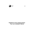
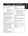
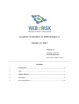
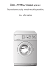
USER MANUAL
DC100G
UNI-RAM CORPORATION • ONTARIO • CANADA
Revision 2010-06
MANUAL - SOLVENT RECYCLER - PRINTING INDUSTRY
DC100G
Revision 2010-06
CONTENTS
INTRODUCTION ............................................................................................................ 3
CAUTIONS AND WARNINGS ........................................................................................ 3
FEATURES AND SPECIFICATIONS ............................................................................. 4
SAFETY FEATURES ...................................................................................................... 4
SOLVENT REQUIREMENTS AND DEFINITIONS ......................................................... 4
DELIVERY INSPECTION ............................................................................................... 5
LOCATION ..................................................................................................................... 5
SET UP AND CONNECTIONS ...................................................................................... 6
OPERATING PARAMETERS ......................................................................................... 9
OPERATION .............................................................................................................. ..10
OPERATION STATUS MESSAGES ............................................................................. 11
ERROR MESSAGES AND TROUBLESHOOTING ...................................................... 12
MAINTENANCE........................................................................................................... 14
REPLACEMENT PARTS ............................................................................................... 15
THEORY OF OPERATION ............................................................................................ 16
WARRANTY ................................................................................................................. 17
2
MANUAL - SOLVENT RECYCLER - PRINTING INDUSTRY
DC100G
Revision 2010-06
INTRODUCTION
Uni-ram holds many patents on designs used in its innovative products. Every machine is tested for compliance with Quality Assurance standards. Follow the instructions on preparation, use and operation to
operate this machine safely and effectively. Ensure that this manual is readily available to the operator at
all times. If you have any questions about the operation of this machine, contact:
North America:
Uni-ram Technical Service
1-800-417- 9133
Other Continents:
Contact Your Supplier
CAUTIONS AND WARNINGS
•
•
•
•
•
•
•
•
•
The operator should wear protective clothing in accordance with local safety and environmental
regulations, with a minimum of face goggles and gloves along with an apron and respirator if required.
Always disconnect the power source before performing maintenance.
DO NOT SMOKE OR USE THIS EQUIPMENT NEAR A POTENTIAL SOURCE OF IGNITION SUCH
AS SPARKS OR AN OPEN FLAME. This unit must be located at least 6 feet (1.8 m) from all potential
sources of ignition including electrical receptacles, switches, pilot lights, fixtures and contacts when
installed in a non - hazardous locations.
The ambient temperature must be between 5°C (41°F) to 35°C (95°F).
DO NOT RECYCLE NITROCELLULOSE WHICH IS EXTREMELY VOLATILE. IT AUTOMATICALLY
IGNITES AT 135 °C TO 166 °C (275°F TO 330 °F). Do not install, operate or maintain this equipment
where the auto ignition temperature of the solvent is lower than 250 °C (482°F).
Do not install, operate or maintain this equipment where the auto ignition temperature of the hazardous atmosphere(s) is lower than 250 °C (482°F).
Solvents that are recycled can be flammable. Establish and follow safe practices to store and handle
solvents.
Units must be installed by a qualified electrician.
Install on a dedicated circuit with sufficient current capacity (see specifications section).
3
MANUAL - SOLVENT RECYCLER - PRINTING INDUSTRY
DC100G
Revision 2010-06
FEATURES AND SPECIFICATIONS
All Uni-ram Solvent Recyclers feature rapid-start direct electric heating of solvent and a short cooldown time due to high-efficiency condensers and air cooling with a motor driven fan.
SAFETY FEATURES
• This unit is certified under UL standard 2208 and CSA standards C22.2 No. 30 and No. 88 for use in
non-hazardous locations as well as for use in hazardous locations Class 1, Division 1, Group D –
T2A and Class 1, Division 2, Group D -T2A.
• Explosion proof construction and intrinsically safe electric circuitry.
• Computer controlled with many built-in safety programs including temperature control of all
critical points including tank, condenser and fan motor.
• Self Diagnostic error messages are displayed on the Display Panel.
• Dual lid cover system.
Warranty: 1 year on unit, 2 years on pump.
*Note on voltage:
SPECIFICATIONS
MODEL
DC100G
VOLTAGE (V)
220/240*
RECOMMENDED CIRCUIT AMPS
30
MAX TEMPERATURE SET POINT
240°C
TANK SIZE
CONDENSER AND FITTING
LID GASKET
SHIPPING DIMENSIONS (WDH)
WEIGHT (LB/KG)
Operating the unit at a lower voltage
(eg: 208V) may result in reduced performance.
20 US GAL (80L)
STAINLESS STEEL
VITON
47” X 27” X 50”
450/205
SOLVENT REQUIREMENTS
Dirty solvent to be distilled must meet each requirement described below. Be sure to read the MSDS
(Material Solvent Data Sheet) on the properties of the pure solvent to be recyled.
•
The BP (Boiling Point) of the dirty solvent must be less than 240°C (464°F). BP increases with greater
contamination. Note: Recycle recently contaminated solvent only. Standing solvent can become acidic
over time.
•
The auto-ignition temperature of the solvent to be distilled must be higher than 250°C (482°F) for safe
operation. Do not recycle Nitrocellulose. The auto ignition temperature is 135°C (275°F).
•
For good water separation to occur, the organic (oil-based) component of the solvent mixture must be
non-miscible in water and have a specific gravity of 0.85 or less.
DEFINITIONS
Flash Point: The lowest temperature at which the vapor of a solvent can be made to ignite momentarily in air.
Auto-ignition temperature (often referred to as “ignition temperature” or “ignition point”): the temperature at which
solvent ignites by itself.
4
MANUAL - SOLVENT RECYCLER - PRINTING INDUSTRY
DC100G
Revision 2010-06
DELIVERY INSPECTION
•
Inspect the shipping carton for any sign of transport damage. Carefully remove the unit from the shipping carton and check the unit for damage. Report any transport damage immediately to the carrier
and your vendor. Initiate a freight claim with the carrier. The manufacturer is not responsible for freight
damage.
•
Check for the parts listed and/or shown below. If any parts are missing, contact your supplier. Additional consumables and accessories are also listed.
Level the unit using the adjustable feet and install the Door Handle (included in the ACCESSORY KIT).
•
CONNECTION HOSE KITS
ACCESSORY KIT
CONTENTS
Manual
Door Handle & 2 Screws
Connection Hose Kits
(see photo on right)
Drum Mixer
Lid Gasket
WATER OUT
DIRTY
SOLVENT IN
CLEAN
SOLVENT OUT
DRUM MIXER
LOCATION
This unit is certified for use in non-hazardous and hazardous locations
Class 1, Division 1 Group D and Class 1, Division 2, Group D.
•
Non-hazardous Locations:
If using a plug rated for non-hazardous locations, the unit must be located outside of a hazardous location. In such a location, we recommend that the receptacle be located a minimum of 6 feet from the
unit and a minimum of 3 feet from the floor. We also recommend that the unit be located at least 6 feet
from electrical receptacles, switches, pilot lights, fixtures etc. To clarify the definition of an appropriate location, contact your local authority. This unit must be connected to the power supply only
by a qualified electrician in accordance with an appropriate Electrical Code.
•
Hazardous Location:
In hazardous locations (Class 1, Division 1, Group D and Class 1, Division 2, Group D), the power
cord must be connected to the main power supply only by a qualified electrician, in accordance with
the National Electrical Code. This equipment must be properly connected to an explosion proof outlet
(receptacle or hard wired).
Select a Location That Meets EACH AND EVERY Requirement, Described Below.
1) Comply with the instructions in the section: CAUTIONS AND WARNINGS.
2) Make sure that the unit is placed in a in a location so that there is plenty of space to manoeuver
the drums, especially when they are full. There must also be enough space behind the unit to accomodate al the hoses, connections and required ventilation. Ensure that the safety lid and door opens fully.
The unit must be in a location where people or equipment cannot disturb the cables or connections. The
cord must be connected directly to the main power supply; an extension cord cannot be used.
5
MANUAL - SOLVENT RECYCLER - PRINTING INDUSTRY
DC100G
Revision 2010-06
SETUP AND CONNECTIONS
1. PLACEMENT OF CONTAINERS
2. POWER CONNECTION
3. AIR CONNECTION
4. LEVEL SENSOR TUBES, SOLVENT-WATER HOSES, DRUM MIXER AIR LINE
5. GROUNDING WIRES
6. CONTAINER CONNECTIONS and ADJUSTNG THE LEVEL SENSOR TUBES
7. DRUM MIXER
8. RECEIVING TANK / WATER SEPARATOR - PRIMING and CONNECTIONS
1. PLACEMENT OF CONTAINERS
Arrange the three containers, shown in the following diagram, in a convenient way that does not block
the free flow of air around the unit. Note: the full containers will be very heavy. Make sure there is
enough space to manoeuver them in a safe manner.
2. POWER CONNECTION
Connect the unit to a dedicated 20A, 200/240V branch circuit using one of the methods described in the
Location section. Note: operating the unit at a lower voltage (eg: 208V) may result in reduced performance. On first power up and when the unit is ready to begin a new cycle, the Display Panel shows
“READY S.P. = XXX°C”. (SP = Set Point, XXX is the set point temperature).
SAFETY
COVER
TANK LID
LID GASKET
CONTROL PANEL
(KEYPAD)
SERVICE PANEL
CLEAN-WATER CONTAINER
FLOAT
DRUM MIXER IN
DIRTY-SOLVENT CONTAINER
CLEAN-SOLVENT CONTAINER
WASTE INK
CONTAINER
6
WATER
SEPARATOR
(INSIDE)
MANUAL - SOLVENT RECYCLER - PRINTING INDUSTRY
DC100G
Revision 2010-06
3. AIR CONNECTION
This unit is equipped with air operated Dual Diaphragm pumps and requires a supply of clean, dry air of at
least 85 PSI (6 kg/cm2) and 2 CFM. Note: If necessary , install a Moisture Filter.
Apply teflon tape to the Air Inlet Fitting (1/4” NPT Female Threads) and connect the Moisture Filter to it, if
necessary. Connect the air supply to the Filter. Connect the air supply directly if a Filter is not used. Make
sure that there are no leakages at the connections. Also make sure that the air is free of dust, rust and
other contaminants. Drain the Moisture Filter before each recycling.
4. LEVEL SENSOR TUBES (ONE RED, ONE CLEAR), SOLVENT-WATER HOSES (3 BLACK), DRUM
MIXER AIR LINE (ORANGE)
Using the picture and table on the next page as a guide, connect the various tubes and hoses to the correct connectors at the back of the solvent recycler.
CONNECTION DIAGRAM
A2
L1
L2
GR
A3
A1
F1
F2
A4
E1
E2
E3
A5
A6
A7
F3
CAUTION: BOTH GROUNDING WIRES
(GR) MUST BE ATTACHED AS SHOWN
A2 Not Used
A1 Air Supply Line with Moisture
Filter (Filter is optional)
L1 Clear Tube for Clean-Water Level Sensor F1 Clean Water OUT to drum
L2 Red Tube for Clean-Solvent Level Sensor F2 Clean Solvent OUT to drum
A3 Not Used
A4 Drain Pressure Toggle Switch*
E1 Remote Status Light (Optional)
E3 Not Used
A5 Air Line for Drum Mixer (Orange Tube)
A6 Not Used
A7 Not Used
F3 Dirty Solvent-Water Mixture IN
E2 Not Used
from dirty drum
* Pressurizes the Distillation Tank during waste draining to improve the flow of exceptionally viscous (thick) material. The default is OFF. Turn ON only when necessary.
7
MANUAL - SOLVENT RECYCLER - PRINTING INDUSTRY
DC100G
Revision 2010-06
5. GROUNDING WIRES
To prevent the build up of static electricity, any container containing solvent must be grounded. The hose
for the dirty solvent and the clean solvent comes with green grounding wire. Connect one end to the
grounding screw on the back of the unit and the other to, either the rim of the solvent container if it is
metal or to the metal pickup rod, if the container is plastic use the “alligator clamp” provided on the container end of the wire to connect to the pick up tube.
6. CONTAINER CONNECTIONS and ADJUSTNG THE LEVEL SENSOR TUBES
The three Connection Kits each have a long metal rod at the container end. This rod is to be placed in the
appropriate drum or container so that it sits on the bottom. See the diagram, Connection Diagram.
The CLEAN-WATER and CLEAN-SOLVENT rods also have a shorter metal tube attached to the long
rod. This shorter metal tube and the attached plastic tube (either red or clear) are part of the level sensing
system. To work correctly and prevent overflow, the position of the shorter metal tube must be adjusted
up or down (using the set screw) so that the bottom opening is about 6 inches below the top of the drum
or container. This tube should not require adjustment if a standard 55 US Gal drum is used. However, if a
smaller container is used, the position will have to be adjusted, as described.
7. DRUM MIXER
• Insert the shaft into the motor section and tighten the Allen screws well.
• Remove the “bung” from the larger opening of the Dirty Solvent Container. Insert the impellor and shaft
into the drum and screw the motor into the opening making sure it is tight. Caution: the motor must
be tightly installed so that the shaft is held in a vertical postion away from the wall of the Drum.
• Connect the Drum Mixer Air Line (orange) to the mixer. Use an air line lubricator (not supplied).
• The speed of the mixer may be adjusted by adjusting the air flow using the Ball Valve (included). The
on-off and duration of mixing is controlled by the computer.
Notes:
1. This Drum Mixer can only be used with a standard 55 US Gal Drum.
2. To prolong the life of the mixer motor, an air line lubricator (not supplied) is recommended. It must be
installed only on the Drum Mixer Air Line (orange). To prevent serious damage to the machine,
DO NOT use an air line lubricator on the main air line.
8. RECEIVING TANK / WATER SEPARATOR - PRIMING and CONNECTIONS
• On initial setup, to prime the separator, add two litres of tap water through the opening in the left side
of the tank (No. 2 below).
• The connections shown below are made at the factory. Use the following information if the connections
are removed and need to be restored.
1
4
3
5
2
1
SOLVENT OUT PUMP
2
WATER OUT PUMP
3
AIR LINE (BLUE)
4
LEVEL SENSOR #1
5
LEVEL SENSOR #2
6
WATER SEPARATOR TANK
7
SOLVENT/WATER MIXTURE INLET
6
7
8
MANUAL - SOLVENT RECYCLER - PRINTING INDUSTRY
DC100G
Revision 2010-06
OPERATING PARAMETERS
The computer is pre-set at the factory and the initial setup of the unit is usually done by a Uni-ram-certified technician. If the inititial solvent mixture is changed or the initial settings need to be fine-tuned, changes can be made by the operator in SETUP mode, described below. For advice on changing the settings,
or to correct a problem during the operation of the unit, call for service (section, INTRODUCTION).
SETUP MODE
We recommend that only personnel with expert understanding of the unit adjust the settings. Adjust set
tings only when the display reads: “READY S.P. = xxx°C”. To start SETUP, press and hold SETUP key
and press START. Use + or - key to adjust setting. To move to the next parameter, press OK.
STEP DISPLAY
KEY TO KEY TO DESCRIPTION
ADJUST ACCEPT
1
LOW AIR PRESSURE
NA
Appears if Air supply is not yet connected.
2
READY S.P. = 200°C
NA
Indicates unit is ready and set to 200°C
3
SET-UP MODE
NA
Indicates SETUP mode is active
4
CYCLES # = 1
+ OR -
OK
Change to 2, see Example Scenario
5
SET-PT = 200°C
+ OR -
OK
Depends on BP of waste mixture
6
LO TEMP PWR = 100%
+ OR -
OK
7
HI TEMP PWR = 80%
+ OR -
OK
8
SWITCH TEMP = 200°
+ OR -
OK
Adjust together to compensate for excessively vigourous vapourization which can
cause leakage at the Lid Gasket.
9
MIXING = 5M
+ OR -
OK
The Drum Mixer mixes the waste mixture.
10
REF. TIME =1H00M
+ OR -
OK
“Refill Time” = duration of Refill Cycle;
Range: 1-24 hours; best setting is max
without loss of ouput
OK
Minimize to allow more Refill Time; best
setting determined by Drain Temp, the nature of the waste content and the “DOWN
SLOPE” setting (set at the factoy or during initial setup).
OK
Increase to lower the viscosity of the
waste or to allow a shorter Post Heat
setting or to reduce the Cool Down time;
decrease if too much odour
11
POST HEAT = 0H00M
12
DRAIN TEMP = 100°C
13
READY S.P. = 200°C
+ OR -
+ OR NA
Indicates unit is ready and set to 200°C
9
MANUAL - SOLVENT RECYCLER - PRINTING INDUSTRY
DC100G
Revision 2010-06
OPERATION
A A typical setting is where CYCLES # = 2 cycles, each cycle is 12-15 hours each.) The operation consists of the following:
1. Press START
The unit will operate continuously for 24 -30 hours and drain the drum of dirty solvent producing clean
solvent and distilled water.
2. CHECK CONTAINERS HOLDING DIRTY SOLVENT, CLEAN SOLVENT AND CLEAN WATER
At the end of the batch remove the dirty drunm, clean solvent drum and clean water drum as necessary. Prepare drums for the next batch.
3. DISPOSE of WASTE INK
Clean the tank, lid and float and dispose of the waste ink residue in the regular waste ink drum.
4. CLEANING AND CHECKING THE DISTILLATION TANK, LID AND FLOAT AFTER EACH “BATCH”
To ensure maximum performance, it is extremely important to clean and maintain the Distillation Tank,
Lid and Float system as follows:
•
Wear protective clothing according to local regulations. A minimum of solvent resistant gloves, googles
and mask are recommended.
•
Make sure the unit is in “READY” mode.
•
Open Safety Cover fully.
•
Unlatch and open the Tank Lid. Use EXTREME CAUTION to avoid damage to the Float System, •
Using a cloth soaked in clean solvent, wipe the Tank Lid interior and the exposed part of the Lid Gasket.
•
While supporting the Float System firmly with one hand, clean the float ball and stem with the other.
•
When finished, check that the float moves freely and that all hardware is tight. If neccesary, re-tighten
any loose hardware.
•
To help in the cleaning of the Tank interior, add solvent to the Tank automatically by activating the
CLEANING MODE cycle: push and hold O.K. button then press STOP. The DISPLAY will read
“CLEANING MODE ?”.
•
Press START to continue or STOP to cancel. If you continue, the drain is closed and the filling pump
runs for about 10 seconds to add some solvent to the tank. This is followed by heating, if necessary.
•
The DISPLAY will then read “READY TO CLEAN” for 5 seconds followed by “PUSH O.K. TO DRAIN”.
Do not press O.K. yet. Proceed with the cleaning.
•
Using a cloth soaked in clean solvent, wipe the Tank walls and bottom. If the residue is baked on,
scrape it off carefully so as to avoid damaging the Tank. When finished, press the O.K. button to
drain the tank.
•
When the Tank is fully drained, wipe the walls clean with a clean cloth.
•
IMPORTANT: Proper sealing of the Tank Lid is essential for both efficiency and safety. Check
that the Lid Gasket is properly seated in the groove and that it is clean. Replace if damaged or
worn (see Maintenance section). Also make sure that the Tank sealing surface is clean and free
of debris.
•
Close the Tank Lid, latch it and lock it down.
•
Check the Lid Tension (sealing tightness). If the Lid appears to be loose in any way or leaking solvent, read and follow the instructions given in the Maintenance Section of this Manual.
• Close the Safety Cover and check that the Locking Mechanism is working properly.
Notes: During the first cycle, check all connections for leaks and watch for any Error Messages. See the
section Error Messages and Troubleshooting for more information on each Error Message.
10
MANUAL - SOLVENT RECYCLER - PRINTING INDUSTRY
DC100G
Revision 2010-06
OPERATIONAL STATUS MESSAGES
The following messages are displayed during normal operation.
DISPLAY
DESCRIPTION
READY S.P. = 200°C
Indicates unit is ready and set to 200°C
DRAIN VALVE CLOSED
Displays for about 5 sec.
AGITATE LEFT = xM
Counts down in minutes.
FILLING
Displays during filling.
HEAT ON
Displays for about 5 sec.
SET-PT = 200°C
Alternates with TANK = xxx°C and VAP EX. = xxx°C
*REFILL = xHxM
Displays during REFILL, counts down in hours and minutes.
*POST HEAT = xHxM
Displays during POST HEAT, counts down in hours and minutes.
TANK = xxx°C
Alternates with SET-PT = 200°C and VAP EX. = xxx°C
VAP EX. = xxx°C
Alternates with SET-PT = 200°C and TANK = xxx°C
COOLING
T1 = xxx°C
Alternate during COOLING.
DRAIN VALVE OPEN
Displays for about 5 sec.
FINAL TRANSFER
Displays during TRANSFER.
READY S.P. = 200°C
Indicates unit is ready and set to 200°C
*REFILL occurs first followed by POST HEAT.
Note: the POST HEAT phase may continue for a while without displaying if the distillation process has
been manually set to a longer time. COOLING will begin when POST HEAT is finished.
11
MANUAL - SOLVENT RECYCLER - PRINTING INDUSTRY
DC100G
Revision 2010-06
ERROR MESSAGES AND TROUBLE SHOOTING
If an abnormal condition is detected by the unit’s Self-diagnostic System, the Display Panel shows one of
the following error messages. To get help in correcting the problem note the massage and call for service.
MESSAGE
DESCRIPTION
REMARKS
LIGHTS & BUZZER
DISCONNECT POWER
Temperature at TC#1
continues to rise by
more than 30˚C within
10 minutes after Heater
is turned off.
Defective Heater TRIAC RED FLASH & BUZZER
is the most likely cause.
Power supply must be
disconnected as soon
as possible.
COND THERMOSTAT
Condenser Thermostat
is open during initial
fault monitoring cycle
Unit will not start
when START button is
pressed until the condenser cools down.
YELLOW STEADY
CONDSR OVER-HEAT
Condenser Thermostat
is open up to 10 min.
Automatically stop
heater.
RED STEADY
CHECK FAN
After 10 min.
Automatically stop process except Fan.
RED STEADY
CHK TANK SENSOR
TC#1 has broken connection
Automatically stop
process
RED STEADY
CHK COND. SENSOR
TC#2 has broken connection
Automatically stop
process
RED STEADY
CHK BOILER FLOAT
If Float shows FULL,
after draining Debris,
Automatically stop
process
YELLOW FLASHING
SEPARATOR FLOAT
One of Level Sensor
Floats of Water Separator is stuck at full position. (Not closed in 90
seconds)
Automatically stop proYELLOW FLASHING
cess. Check Level sensors and transfer pumps
for defect. Press START
to resume process from
where stopped.
CHK HEAT CIRCUIT
Operation and Selftest message. There is
opening in Heater circuit
LOW AIR PRESSURE
Before and during air
solenoid operation.
Automatically stop proYELLOW FLASHING
cess. Pressure recovery
will re-start from where it
stopped.
LOW WASTE LEVEL
Filling time-out in Initial
Filling. (Both Boiler
Level Sensor #1 and #2
did not open.)
Process is terminated.
Replenish waste source
and press START
button, operation will
resume from where it
stopped.
REFILL TIME-OUT
Float Switch did not
The process will be
open within pre-set refill- competed and this
ing time.
display will show at the
end. Pressing STOP
button will return to
READY mode.
YELLOW STEADY
12
YELLOW STEADY
YELLOW STEADY
MANUAL - SOLVENT RECYCLER - PRINTING INDUSTRY
DC100G
Revision 2010-06
ERROR MESSAGES AND TROUBLE SHOOTING - continued
MESSAGE
DESCRIPTION
REMARKS
LIGHTS & BUZZER
BOILING TIME-OUT
No vapor within factory
pre-set time.
Automatically stop
process
YELLOW STEADY
LO VOLTAGE RESET
Low Voltage power
supply happened during
process.
Automatically stop
YELLOW STEADY
process. Press “START”
and it will resume from
where it stopped.
RESET OCCURRED
Power supply irregularity happened during
process.
The process was
automatically stopped.
Press “START” and it
will resume from where
it was stopped.
YELLOW STEADY
WAIT FOR READY
This message is displayed for 5 seconds
when START button is
pressed before READY
mode.
After 5 seconds, display
will return to COOLING
T=XXXC.
N/A
OUTPUT DRUM FULL
Water Drum or Solvent
Drum Level Sensor (NC
Micro Switch) detects
FULL level..
Automatically stop process. Replace the clean
pail and press “START”.
It will resume from
where it stopped.
YELLOW FLASHING
DEBRIS PAIL FULL
Debris weight sensor
(NC Micro Switch) detects FULL weight..
Automatically stop proYELLOW FLASHING
cess. Empty the debris
pail and press “START”.
It will resume from
where it stopped.
WATCH DOG RESET
Software integrity has
Automatically stop probeen temporarily halted. cess. Press “START”. It
will resume from where
it stopped.
YELLOW FLASHING
ILLEGAL OPCODE
Software malfunction
Automatically stop prohappened and has been cess. Press “START”. It
temporarily halted.
will resume from where
it stopped.
YELLOW FLASHING
ILLEGAL ADDRESS
Software malfunction
Automatically stop prohappened and has been cess. Press “START”. It
temporarily halted.
will resume from where
it stopped.
YELLOW FLASHING
13
MANUAL - SOLVENT RECYCLER - PRINTING INDUSTRY
DC100G
Revision 2010-06
MAINTENANCE
CAUTION: Wear protective clothing according to local regulations. A minimum of solvent resistant
gloves, googles and mask are recommended.
CHECKING AND INCREASING LID TENSION (BY ADJUSTING THE SPRING BOLT)
Some decrease in tension or lid tightness is normal with average use. This procedurre should
only be done if the Lid is leaking solvent or there is excessive looseness.
Before following this procedure, check for a worn Lid Gasket or loose Hinge Bolts. Replace the Lid Gasket or tighten the Hinge Bolts as needed. If the Lid appears to be sealing tightly but is leaking solvent,
the poblem may be a blockage in the solvent flow path or a set point that is too high for the solvent being
recycled. Call for service. If the Lid is not leaking solvent but still appears to be too loose, follow this procedure to increase the Lid tension.
This procedure tightens the Lid by increasing
the tension on the spring attached to the Lid Bar
Spring Bolt Assembly. The Lid and Bolt Assembly is carefully designed as a Safety Pressure
Relief system to prevent a dangerous build up of
pressure inside the closed tank. Do not adjust
the Spring Holding Nut by more than 2 full
turns maximum. If 2 full turns do not solve the
problem, call for service.
Bolt Head
Spring Holding Nut
•
•
Spring Bolt Assembly
While holding the Bolt Head with a wrench,
turn the Spring Holding Nut no more than a
1/2 turn at a time. Turn in a counter- clockwise direction (as you look down on it).
After each 1/2 turn, operate the unit normally
and check for leaks.
REPOSITIONING LID and TIGHTENING HINGE BOLTS
The Hinge bolts can loosen over time, causing the lid to shift off center. This can lead to an inadequate
seal and leaking around the Gasket. Loosen the bolts, reposition the lid and re-tighten the bolts.
Hinge
Spring Bolt Assembly
Cross Bar
14
MANUAL - SOLVENT RECYCLER - PRINTING INDUSTRY
DC100G
Revision 2010-06
MAINTENANCE
REPLACING LID GASKET
Remove the old gasket by prying it out gently with a screw driver. Place the new gasket in the groove and
press in firmly all around.
REPLACEMENT PARTS
DESCRIPTION
PART NO.
SAFETY COVER
960-3310
KEYPAD
900-3461
DIAPHRAGM PUMP, 2”
UDP2TS
DIAPHRAGM PUMP, 4”
UDP4TASS
DRUM MIXER
960-9040
LID GASKET, VITON
965-2150V
DOOR HANDLE & 2 SCREWS
120-318S & 99-404S
CONNECTION KIT, SOLVENT IN
965-4910
CONNECTION KIT, SOLVENT OUT
965-4920
CONNECTION KIT, WATER OUT
965-4930
15
MANUAL - SOLVENT RECYCLER - PRINTING INDUSTRY
DC100G
Revision 2010-06
THEORY OF OPERATION - DISTILLATION PROCESS
Waste solvent consists of the original solvent plus liquid and solid materials picked up during use of the
solvent. Recycling separates the original solvent from the waste materials. During the recycling process,
the distillation tank fills with dirty solvent and the heating element heats the mixture. The solvent mixture
boils and the vapour passes through a cooling condenser where purified, clean solvent, ready for use
condenses out. Waste materials in the dirty solvent boil at a temperature substantially above the Temperature Set Point so they remain in the distillation tank for disposal.
Solvent Recycling
Vapour Outlet tube
(vapor moves
to cooling condenser
from distillation tank)
Distillation
Tank
Condenser
(cools vapor
to a liquid)
Heating Element
Receiving Pail
(contains clean,
recycled solvent)
Distillation Cycle
1.
2.
3.
4.
5.
6.
Heating starts, temperatue rises
Vapourization starts
Vapourization ends, AUTO SHUT-OFF / BAKE TIME starts (see SETUP)
Baking finishes, cooling begins
Cooling is complete
Separation occurs
Temp SET
POINT
4
2
3
5
1
TEMP TIME
16
6
MANUAL - SOLVENT RECYCLER - PRINTING INDUSTRY
DC100G
Revision 2010-06
Full Product Warranty
These Uni-ram products have been engineered and manufactured to high performance standards. Each
unit has been subjected to detailed factory testing before shipment.
This product comes with a one-year full warranty from the date of purchase. Uni-ram Corporation reserves the right to repair or replace the unit, free of charge, to the original purchaser if a part is found to
be defective in material or workmanship as determined by factory service personnel. The items listed
below under “Conditions of Warranty” as consumables are not covered.
Uni-ram reserves the right to direct the customer to ship the unit collect to the Uni-ram factory or to an approved Service Center for repair using the Uni-ram Return Goods Procedure or to repair the unit on-site.
To prevent damage in transport, the purchaser must ship the unit in the original packaging or use alternate adequate packaging. All units must be shipped clean and free of solvent.
Conditions of Warranty:
As Uni-ram Corporation has no control over the working conditions or circumstances under which the
purchaser stores, handles or uses the product, Uni-ram makes no warranty or claim, either expressed or
implied with respect to this product’s fitness for any purpose or the result to be obtained from its use. This
condition applies to the sale of all products and no representative or distributor of Uni-ram Corporation
has the authority to waive or change these conditions.
This warranty applies only to the original purchaser and does not apply if the unit has been misused,
overloaded, neglected, altered or used for any purpose other than those specified in the operating and
installation instructions. Deterioration due to normal wear is not covered by this warranty. Damage due to
accident, transportation, fire, floods or acts of God is also not covered. Units whose serial numbers have
been altered or removed are not covered. The warranty is invalid if unauthorized abrasives are used in
this unit. Unauthorized attempts at self-repair or alterations by the owner also invalidate this warranty.
Interior or exterior finishes are not covered by this warranty.
Consumable Items are not covered by this warranty.
This warranty replaces all other warranties expressed or implied by statute or otherwise.
To make a claim, call Uni-ram Service at 1-800-417-9133 and quote the serial number of the unit.
SERIAL NUMBER: ___________________________________________
PURCHASE DATE: ____________________________________________
PURCHASED FROM: ________________________________________________
17