1
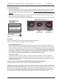
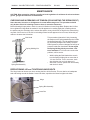
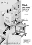
MANUAL - SOLVENT RECYCLER - PRINTING INDUSTRY
DC100G
Revision 2010-06
5. GROUNDING WIRES
To prevent the build up of static electricity, any container containing solvent must be grounded. The hose
for the dirty solvent and the clean solvent comes with green grounding wire. Connect one end to the
grounding screw on the back of the unit and the other to, either the rim of the solvent container if it is
metal or to the metal pickup rod, if the container is plastic use the “alligator clamp” provided on the container end of the wire to connect to the pick up tube.
6. CONTAINER CONNECTIONS and ADJUSTNG THE LEVEL SENSOR TUBES
The three Connection Kits each have a long metal rod at the container end. This rod is to be placed in the
appropriate drum or container so that it sits on the bottom. See the diagram, Connection Diagram.
The CLEAN-WATER and CLEAN-SOLVENT rods also have a shorter metal tube attached to the long
rod. This shorter metal tube and the attached plastic tube (either red or clear) are part of the level sensing
system. To work correctly and prevent overflow, the position of the shorter metal tube must be adjusted
up or down (using the set screw) so that the bottom opening is about 6 inches below the top of the drum
or container. This tube should not require adjustment if a standard 55 US Gal drum is used. However, if a
smaller container is used, the position will have to be adjusted, as described.
7. DRUM MIXER
• Insert the shaft into the motor section and tighten the Allen screws well.
• Remove the “bung” from the larger opening of the Dirty Solvent Container. Insert the impellor and shaft
into the drum and screw the motor into the opening making sure it is tight. Caution: the motor must
be tightly installed so that the shaft is held in a vertical postion away from the wall of the Drum.
• Connect the Drum Mixer Air Line (orange) to the mixer. Use an air line lubricator (not supplied).
• The speed of the mixer may be adjusted by adjusting the air flow using the Ball Valve (included). The
on-off and duration of mixing is controlled by the computer.
Notes:
1. This Drum Mixer can only be used with a standard 55 US Gal Drum.
2. To prolong the life of the mixer motor, an air line lubricator (not supplied) is recommended. It must be
installed only on the Drum Mixer Air Line (orange). To prevent serious damage to the machine,
DO NOT use an air line lubricator on the main air line.
8. RECEIVING TANK / WATER SEPARATOR - PRIMING and CONNECTIONS
• On initial setup, to prime the separator, add two litres of tap water through the opening in the left side
of the tank (No. 2 below).
• The connections shown below are made at the factory. Use the following information if the connections
are removed and need to be restored.
1
4
3
5
2
1
SOLVENT OUT PUMP
2
WATER OUT PUMP
3
AIR LINE (BLUE)
4
LEVEL SENSOR #1
5
LEVEL SENSOR #2
6
WATER SEPARATOR TANK
7
SOLVENT/WATER MIXTURE INLET
6
7
8