1
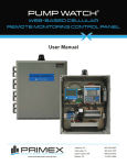
PUMP WATCH MULTI ™ WEB-BASED CELLULAR REMOTE MONITORING CONTROL PANEL User Manual 844-4PRIMEX (477-4639) WWW.PRIMEXCONTROLS.COM Ashland, OH 800-363-5842 Clearwater, FL 800-349-1905 Detroit Lakes, MN 888-342-5753 Milford, OH 513-831-9959 WARNINGS Failure to read and understand the information provided in this manual may result in personal injury or death, damage to the product or product failure. Please read each section in its entirety and be sure you understand the information provided in the section and related sections before attempting any of the procedures or operations given. Failure to follow these precautions could result in serious injury or death. Keep these instructions with warranty after installation. This product must be installed in accordance with National Electrical Code, ANSI/NFPA 70 so as to prevent moisture from entering or accumulating within the controller housing. ELECTRICAL SHOCK HAZARD A qualified service person must install and service this product according to applicable codes and electrical schematics. Disconnect power prior to servicing any equipment within the Pump Watch™ Multi panel. • Do not connect power to this equipment if it has been damaged or has any missing parts. • Do not install in areas with: excessive or conductive dust, corrosive or flammable gas, moisture or rain, excessive head, regular impact shocks, or excessive vibration. EXPLOSION OR FIRE HAZARD Do not use this product with flammable liquids. Do not install in hazardous locations as defined by National Electrical Code, ANSI/NFPA 70. PRIMEX® Pump Watch™ Remote Monitoring Panel User Manual TABLE OF CONTENTS Introduction & Ordering Information ........................................................... 1 Pump Watch™ Multi Panel Introduction ...................................................... 2 Receiving and Inspection............................................................................ 2 Tools & Additional Materials Required ....................................................... 3 Mounting the Pump Watch™ Multi Panel .................................................... 4 Wiring Methods ........................................................................................... 5 System View ............................................................................................... 6 Wiring .......................................................................................................... 7 Sensor Wiring ............................................................................................. 8 Pump Watch™ Multi Troubleshooting.......................................................... 9 Station View™ Multi Introduction & Specifications .................................... 10 Programming ............................................................................................ 11 I/O Terminal Configuration........................................................................ 24 Dimensions & Mounting ............................................................................ 24 Pump Watch™ Gateway Features............................................................. 25 Home Screen ............................................................................................ 26 System Setup ........................................................................................... 26 Pump Watch™ Gateway Troubleshooting ................................................. 27 Activation and Service .............................................................................. 28 Logging In ................................................................................................. 28 Access Levels ........................................................................................... 29 Viewing/Searching for Gateways .............................................................. 30 Placing Controllers on the Map ................................................................ 32 User Setup ................................................................................................ 33 Dashboard ................................................................................................ 34 Station Setup ............................................................................................ 35 Editing Labels ........................................................................................... 36 Station Data Visualization ......................................................................... 37 Alarm Notification Setup ........................................................................... 38 Reports & Trending................................................................................... 39 PRIMEX® Pump Watch™ Remote Monitoring Panel User Manual INTRODUCTION Designed for almost any system requiring remote monitoring of key data, the Pump Watch™ is a simple and effective tool for management of a system via a cellular network. Alarms are monitored and service personnel notified in the event of a failure. Data logging and trending of critical information enables the User to visually track system performance and recognize impending problems. The station data can be visualized in a simple and intuitive way from your web browser on a PC, tablet or smart phone. ORDERING INFORMATION Pump Watch™ Multi Panel (NEMA 4 enclosure). Note: All Pump Watch™ units include 2 years of cellular service. 1. 2. Pump Watch™ Multi For installation outside a control panel or for retrofit applications Includes: • 14x12x6 NEMA 4X thermoplastic enclosure • Pump Watch™ Gateway • DC Power supply and battery backup • Requires 120 VAC supply power 7711 • I/O terminals for hardwiring with existing control panel ™ • Station View - Multi mode (no control) • Can monitor almost any system or configuration 7711 77 7 71 711 7 1 11 1 Pump Watch™ Multi Options • High Gain Antenna (pole mounted) • Low Loss Cable - 40ft (cable cannot be spliced.) PRIMEX® 1 Pump Watch™ Multi Panel User Manual PUMP WATCH™ MULTI INTRODUCTION The Pump Watch™ Multi remote monitoring system is designed to be connected to almost any system or control panel. The Pump Watch™ Multi control panel is a more flexible version of the Pump Watch™ Retro system dedicated to wastewater lift station controls. All of this data is then relayed to the cloud, via a cellular network, to a secure website, and can be accessed and monitored from virtually anywhere in the world. RECEIVING AND INSPECTION PUMP WATCH MULTI ® WEB-BASED CELLULAR REMOTE MONITORING CONTROL PANEL User Manual WWW.PRIMEXCONTROLS.COM PRIMEX® 2 Ashland, OH 800-363-5842 Clearwater, FL 800-349-1905 Detroit Lakes, MN 888-342-5753 Milford, OH 513-831-9959 Pump Watch™ Multi Panel User Manual TOOLS & ADDITIONAL MATERIALS REQUIRED Drill and drill-bit Phillips screwdriver Lag bolts Liquid-tight conduit Wire cutter Wire stripper Flat screwdriver Small flat screwdriver Machine screws *Submersible Pressure Transducer Liquid-tight conduit fittings Conduit Caulking gun and Silicone caulking Ratchet with sockets Unistrut *May already be available in the existing lift station control panel. PRIMEX® 3 Pump Watch™ Multi Panel User Manual MOUNTING THE PUMP WATCH™ MULTI PANEL Mount the Pump Watch™ panel using a solid base such as treated posts with a treated plywood overlay. Mounting on Unistrut or other metal structure is also common. Please use the appropriate hardware for securely anchoring the panel to the metal structure. TOOLS & MATERIALS NEEDED Lag bolts Drill and drill-bit Circular saw Ratchet with sockets Treated Posts Treated Plywood ! WARNING! Do not mount the panel where there is the possibility of water submergence. PRIMEX® 4 Pump Watch™ Multi Panel User Manual WIRING METHODS When wiring the Pump Watch™ panel, be sure to use liquid-tight conduit or strain relief fittings. TOOLS & MATERIALS NEEDED 7711 771 7 77 7 71 11 11 Drill and drill-bit Flat screwdriver Caulking gun and Silicone caulking CONDUIT OPTIONS OR Liquid-tight conduit fittings Conduit Liquid-tight conduit Use liquid tight fittings and conduit to run cables between the Pump Watch™ Multi and the Lift Station control panel. Do not run conduit from the Pump Watch™ Multi to the wet well. PRIMEX® 5 Pump Watch™ Multi Panel User Manual SYSTEM VIEW PUMP WATCH™ MULTI INSTALLATION EXAMPLE PRIMEX® 6 Pump Watch™ Multi Panel User Manual WIRING SCHEMATIC PRIMEX® 7 Pump Watch™ Multi Panel User Manual SENSOR WIRING PUMP RUN SIGNAL EXAMPLE Wire the pump run inputs to a non-powered auxiliary contact in the control panel, which closes when the pump is called to run. These must be wired for each pump. Motor contactor auxiliary contacts for reference only. Actual contactor configuration may differ. PRIMEX® 8 Pump Watch™ Multi Panel User Manual PUMP WATCH™ MULTI TROUBLESHOOTING PROBLEM No reading from transducer. (level, current, etc.) No flow reading is present. Station View™ Multi controller display is off. CAUSE (S) Transducer wired incorrectly. Damaged or broken cable. Faulty transducer. The Station View™ Multi controller is configured incorrectly. Damaged or broken cable. Faulty flow meter. There is no power supplying the panel. The main breaker is off. The fuse is blown. Faulty power supply. Faulty Station View™ Multi controller. The Pump Watch™ panel is not powered on. The Pump Watch™ web interface is not updating. Repair/connect the supply power. Turn the main breaker on. Check for damaged or shorted wiring and replace the fuse. Check for a green indicator on the power supply and call factory for a replacement if not illuminated. Call factory for a replacement. Ensure panel is powered. Move the Pump Watch™ panel to a less obstructed location The cellular signal strength is too or purchase a high gain, poleweak. mountable antenna to increase cellular strength. The Pump Watch™ website is experiencing problems. PRIMEX® SOLUTION (S) Check transducer connection. Repair the transducer cable. Replace the transducer. Check the Station View™ Multi controller flow configuration. Repair the flow meter cable. Replace the flow meter. 9 Call the AMI™ customer support number. 1-888-280-2060 Pump Watch™ Multi Panel User Manual STATION VIEW™ MULTI INTRODUCTION & SPECIFICATIONS GENERAL Control system monitoring. 4-20mA transducer monitoring (configurable) Pump flow monitoring with level transducer or flow meter (pulsed) Digital input monitoring (configurable) Graphic display with easy navigation and intuitive setup. LCD backlit display. 128x64 pixels Real Time clock NEMA 4X (Front panel) REMOTE TELEMETRY UNIT FEATURES: Level/flow monitoring Tank level in feet Pump run indication SYSTEM Number of starts for each pump/24hrs Run time for each pump/24hrsGPM for each pump (with transducer) Real time clock Password protection ELECTRICAL SPECIFICATIONS (configurable I/O) 10 Digital inputs Pump 1, 2, 3 Run Alarm 1, 2, 3, 4, 5, 6 (User defined) 2 analog inputs (4-20mA) AI0 (User defined) AI1 (Level transducer) 4 Relay ouputs CR1, CR2, CR3 (Remote controlled relays) CR4 (Remote Control Alarm Acknowledge) 24Vdc power, 5.2W Battery backup COMMUNICATION Serial port: RS 485 Modbus RTU slave CERTIFICATION UL listed POWER UP SCREEN & REVISION PRIMEX® 10 Station View™ Multi Controller User Manual PROGRAMMING MAIN SCREEN The main screen gives the operator an overview of the pump station status. Level Transducer Mode Connected to Pump Watch® Alarm indication Pumps Running Message Display KEY PAD OPERATION The remote telemetry unit keypad is used for screen navigation and data entry. Press F1 to acknowledge alarms PRIMEX® 11 Station View™ Multi Controller User Manual MAIN MENU NAVIGATION Navigation from the Main screen to the Menu Screens. Press PRIMEX® to go back to the previous screen at any time. 12 Station View™ Multi Controller User Manual ACTIVE ALARMS If an alarm event occurs, it is displayed on the message bar on the Main Screen. A flashing alarm bell is also displayed. Possible alarms include: # DISPLAY DEFINITION FIX 0 HIGH LEVEL ALARM Level in the wet well has exceeded the High Level set point Check pump operation, check in flow, check level transducer 1 LOW LEVEL ALARM Level in the wet well has exceeded the Low Level set point Check pump operation, check in flow, check level transducer 2 LEVEL XDCR FAULT Transducer signal less than 4mA Check transducer connection, check transducer and vent tube 3 AIO HIGH ALARM AIO signal exceeded AIO high set point Check system monitored by AIO 4 AIO LOW ALARM AIO signal below AIO low set point Check system monitored by AIO 5 AIO SENSOR FAULT Transducer signal is less than 4mA Check transducer connection, check transducer vent if applicable 6 ALARM 1 Alarm 1 signal active Check system monitored by Alarm 1 input 7 ALARM 2 Alarm 2 signal active Check system monitored by Alarm 2 input 8 ALARM 3 Alarm 3 signal active Check system monitored by Alarm 3 input 9 ALARM 4 Alarm 4 signal active Check system monitored by Alarm 4 input 10 ALARM 5 Alarm 5 signal active Check system monitored by Alarm 5 input 11 ALARM 6 Alarm 6 signal active Check system monitored by Alarm 6 input PRIMEX® 13 Station View™ Multi Controller User Manual SET UP This menu is used for setting up the number of pumps in the system, level sensing data, flow sensing, current sensing, dry run alarm, max. run time, high amp alarm, the system date/time, the system password, and the pump data. Press PRIMEX® to go back to the previous screen at any time. 14 Station View™ Multi Controller User Manual LEVEL SETUP The Station View™ Multi controller is intended to use an analog (4-20mA) transducer to monitor the level of the wet well, as well as for flow calculations. The use of the level transducer can be configured here. Level Config. Level Config. Transducer: Used F1: Set Levels Transducer: Not Used F1: Set Levels F2: Set Transducer F2: Set Transducer Level Setpoints 2.0 Low 3.0 Stop 4.0 Start 7.0 High 1 2 3 4 5 6 7 8 9 0 Level Setpoints 2.0 Low 3.0 Stop 4.0 Start 7.0 High Level Setpoints 3.0 Stop 4.0 Start Start pump 7.0 High 1 2 3 4 5 6 7 8 9 Start 0 Level Setpoints 2.0 Low 3.0 Stop 4.0 Start Stop 7.0 High Level Setpoints 2.0 Low Diameter Volume for Flow Calculation Stop pump The Level Setpoints are not used for controlling the pump. They are used for volumetric flow calculation and alarms only. The flow calculation is based on the diameter of the tank (see Flow Setup), the Start and Stop Level Setpoints, and the fill and discharge times. Both In-Flow and Discharge flow are calculated during every cycle. Low = Low level alarm. Activates a low level (transducer) alarm condition. Stop = Stop level. The flow calculation cycle will stop. (Set a few inches above the actual pump stop level.) Start = Start level. The flow calculation cycle begins. (Set a few inches below the actual pump start level.) High = High level alarm. Activates a high level (transducer) alarm condition. Transducer setup example: 0-10 psi range level transducer = 0-23.0 ft. (1 psi = 2.30 ft.) Set 20mA = 23.0 ft. Some transducers are already calibrated in feet. (e.g. Max value for 20mA is 99.9 ft) When using a submersible pressure transducer, 0.0 ft. represents the level at the bottom of the transducer and not the wet well. If the transducer is mounted 2.0 ft off the bottom of the tank. Set the offset = 2.0 ft. (Max value - 10.0 ~ 10.0 ft) Press PRIMEX® to go back to the previous screen at any time. 15 Station View™ Multi Controller User Manual FLOW SETUP Volumetric flow measurement is available when a level transducer is used in a cylindrical tank. The controller calculates the volume of liquid based on the level. The flow is flow rate is calculated by using the volume and the fill/discharge times. The in-flow and the discharge flow is measured. The controller can also use the flow meter with a pulse output to measure the flow of the system. Alternatively, the flow measurements can be disabled. Flow Config. Flow Config. Flow Sensor: Level F1: Tank Dim. Flow Sensor: Pulse F1: Tank Dim. F2: Pulse Setup F2: Pulse Setup Flow Config. Flow Sensor: Not Used F1: Tank Dim. F2: Pulse Setup Gallons per Pulse Volumetric Flow Tank diameter 4 4.4 1 2 3 1 2 3 4 5 6 4 5 6 7 8 9 7 8 9 Press 0 When using a rectangular tank, the equivalent diameter would be: d=2 LxW/ Example: A 10X10 tank would equate to a diameter of 11.28. Enter this value and get the flow calculations as if it was a cylindrical tank. L= length, W= width. 0 to go back to the previous screen at any time. AIO SENSOR SETUP The controller is able to be used with any 4-20mA transducer to measure any analog value for pumps in the system. The AIO measurement can also be disabled. AIO Setup AIO Setup 10.0 10.0 Used Used 1 2 3 4 5 6 7 8 9 AIO Setup 0 10.0 Not Used Press PRIMEX® to go back to the previous screen at any time. 16 Station View™ Multi Controller User Manual AIO LOW SETUP AIO Low setup is used to monitor a “low alarm” condition on the AIO analog input. AIO Low Alarm 4.0 AIO Low Alarm 4.0 Setpoint Setpoint 1:00 Trip Delay 1:00 Trip Delay 1 2 3 1 2 3 4 5 6 4 5 6 7 8 9 7 8 9 Press 0 0 to go back to the previous screen at any time. AIO HIGH SETUP AIO High setup is used to monitor a “high alarm” condition on the AIO analog input. AIO High Alarm 4.0 AIO High Alarm 4.0 Setpoint Setpoint 1:00 Trip Delay 1:00 Trip Delay 1 2 3 1 2 3 4 5 6 4 5 6 7 8 9 7 8 9 Press PRIMEX® 0 0 to go back to the previous screen at any time. 17 Station View™ Multi Controller User Manual TIME & DATE SETUP It is important that the correct time and date is entered for accurate logging and alarm data collection. Time & Date Time & Date 12:00:00 1/15/14 12:00:00 Wed 1/15/14 Wed 1 2 3 1 2 3 4 5 6 4 5 6 7 8 9 7 8 9 Press 0 0 to go back to the previous screen at any time. PASSWORD SETUP The password function is designed to prevent unauthorized access to the Menu. Set to “0” to disable this function. The password entry screen will appear when entering the menu if the password function is enabled. Press PRIMEX® 1 2 3 4 5 6 7 8 9 0 to go back to the previous screen at any time. 18 Station View™ Multi Controller User Manual PUMP DATA SETUP The Pump Data screen is for information only. It is a record of the pump HP, Volts, and FLA. This data can be viewed remotely when connected to the Pump Watch™ cellular monitoring system. Pump Data 444 HP 444 Vac Pump Data Pump Data 444.4 FLA 10 HP 230 Vac 28.4 FLA 10 HP 230 Vac 28.4 FLA 1 2 3 1 2 3 1 2 3 4 5 6 4 5 6 4 5 6 7 8 9 7 8 9 7 8 9 Press 0 0 0 to go back to the previous screen at any time. I/O STATUS These screens can be used to view all the digital and analog inputs and relay output status. These screens make troubleshooting simple. Digital inputs and output change color when ON. Digital Outputs can be tested by pressing buttons 7, 8, 9 and 0, only while the digital I/O screen is active. Menu I/O Status Analog 0 1 2 3 4 Digital Out 5 6 7 8 9 0 1 2 3 Digital In PRIMEX® (Simul. 7890) Digital ANO 99.9 mA AN1 99.9 mA 19 99.9 99.9 ft Station View™ Multi Controller User Manual I/O STATUS INPUT TERMINALS INPUT TERMINALS TERM INPUT 15 I0 DIGITAL PNP TYPE FLOWMETER (HIGH SPEED PULSED) DESCRIPTION 14 I1 DIGITAL PNP PUMP 1 RUNNING 13 I2 DIGITAL PNP PUMP 2 RUNNING 12 I3 DIGITAL PNP PUMP 3 RUNNING 11 I4 DIGITAL PNP ALARM 1 10 I5 DIGITAL PNP ALARM 2 9 I6 DIGITAL PNP ALARM 3 8 I7 DIGITAL PNP ALARM 4 7 I8 DIGITAL PNP ALARM 5 6 I9 DIGITAL PNP ALARM 6 5 AN1 4-20 mA LEVEL TRANSDUCER 4 AN0 4-20 mA ANALOG INPUT (CONFIGURABLE) 3 GRND 2 0V POWER SUPPLY 0V 1 24V POWER SUPPLY +24Vdc GROUND I/O STATUS OUTPUT TERMINALS OUTPUT TERMINALS TERM 1 2 3 4 5 6 7 8 9 10 11 12 INPUT O0 O1 O2 O3 O4 O5 TYPE DESCRIPTION RELAY C RELAY 1 RELAY NO RELAY C RELAY 2 RELAY NO RELAY C RELAY 3 RELAY NO RELAY C ALARM ACKNOWLEDGE RELAY NO RELAY C NOT USED RELAY NO RELAY C NOT USED RELAY NO 13 O6 TRANSISTOR NOT USED 14 O7 TRANSISTOR NOT USED PRIMEX® 20 Station View™ Multi Controller User Manual DATA LOG The Station View™ Multi controller will log daily station data for 7 days + today’s data since midnight. This data is very useful for tracking high in-flow events and pump performance. Menu Data Log Today P1 P1 124 123 Cyc P2Pump 2 Cyc 567 min P2 678 min Sunday P1 P1 126 125 Cyc P2Pump 2 Cyc 567 min P2 678 min Saturday P1 P1 112 Cyc P2Pump 122 2 Cyc 560 min P2 678 min Cyc = number of cycles (pump starts) min = pump run time in minutes Press PRIMEX® to go back to the previous screen at any time. 21 Station View™ Multi Controller User Manual STATION LOG The Station View™ Multi controller will log station data continually throughout the day. This data is very useful for tracking the current pump performance. The pumping cycles, run time, incoming flow, and current pump flow data is displayed. Menu Station Station 24h P1 P2 P3 Press GPM Minutes Pump 2 7 IN 234 8 232 9 230 12 Cycles 123 124 125 to go back to the previous screen at any time. ALARMS The Station View™ Multi controller will log station alarm data continually. This data is very useful for tracking any recurring abnormalities in the pumping system. The date and time of the activation of each alarm, when the alarm was cleared, when the alarm was acknowledged, and the total duration of the alarm can be viewed on this screen. Menu Alarms Alarm History Group ID 0 001 Rise Fall Ack Res Press PRIMEX® HIGH LEVEL FLOAT 12/31/13 09:50 Duration Pump 2 12/31/13 09:51 00:01:00 12/31/13 09:50 12/31/13 09:51 to go back to the previous screen at any time. 22 Station View™ Multi Controller User Manual ALARMS ACKNOWLEDGE The controller is equipped with an alarm acknowledge function. Upon a fault event, the user will be required to Acknowledge the fault by pressing F1 on the main screen or by remotely pressing the Ack button on the Pump Watch™ web portal. When this function is enabled, the timer will start after a fault, and if not acknowledged before time out, a general fault will occur and notify other users. Disable if not needed. Alarms Ack. Alarms Ack. 99:99 99:99 Press PRIMEX® 1 2 3 4 5 6 7 8 9 Alarms Ack. 99:99 0 Used to go back to the previous screen at any time. 23 Station View™ Multi Controller User Manual I/O TERMINAL CONFIGURATION DIMENSIONS AND MOUNTING PRIMEX® 24 Station View™ Multi Controller User Manual PUMP WATCH GATEWAY FEATURES ™ Front View Cellular Antenna Selector Knob “Back” Button Display Screen “OK” Button Indicator Lights TTL Connector Ethernet Port Modbus Connector Power Connection 24VDC Top View Bootloader Connector Program Switch Sim Card Slot Cellular Antenna Mini USB Connector PRIMEX® 25 Pump Watch™ Cellular Remote Monitor User Manual HOME SCREEN The Home screen displays four (4) different options and is your gateway to all features. Aqua Management, Inc Modbus PLC Monitor Setup SYSTEM SETUP DATE AND TIME 1. Turn the Select knob until the arrow is in front of Date Time and click the OK button. 2. Turn the Select knob until the arrow is in front of Hour (military time) and click the OK button. 3. Turn the Select knob to reach desired hour and click the OK button to accept. 4. Repeat the process for Hour, Second, Month, Day, Year as necessary. 5. Click on the Back button to return to the Setup screen. Setup Date Time Comm COMM From the Setup screen, turn the Select knob until the arrow is in front of Comm and click the OK button. This screen will give you the following information: • Unit ID • MAC Address • RSSI (reception strength) • Carrier • APN • IP Address • Port • Online/Offline Status Unit ID: XXXX MAC Adr: 0 0 5 0 C 2 F 1 A 1 2 0 RSSI :12 Carrier : X X XXXX APN: nPhase… Ico XX . XX . XX . XX Port : XXXX Status: O N L I N E This screen will also give you the current application version and date of the most recent update. PRIMEX® 26 Pump Watch™ Cellular Remote Monitor User Manual PUMP WATCH™ GATEWAY TROUBLESHOOTING PLC COMMMUNICATION If your device is not communicating with the external device you are connected to, you need to check the PLC connection. To check the status from the main screen, turn the Select knob until the arrow is in front of Monitor. Aqua Management, Inc Monitor TUE HH:MM.SS MMM/DD/YY Modbus PLC Last Poll : PLC Comm : OK Rules : Monitor Setup HH:MM.SS PLC Comm should read “OK” if the external device is communicating with the controller. ERROR CODES 0X0100 TEMP_RULE_BIT 0X0200 ACTION_BIT 0X1000 MULTI1_BIT 0X2000 MULTI2_BIT 0X4000 MULTI3_BIT 0X8000 MULTI4_BIT GATEWAY COMMUNICATION If the Gateway is comminicating to the external device, the User is unable to view the data on the user interface or control device remotely, the connection may be disrupted. The user can check the Gateway’s signal strength (RSSI) on the Pump Watch™ unit. RSSI THRESHOLDS RSSI is a measurement of the power present in a received radio signal (Received Signal Strength Indicator). The larger the number, the better the reception. Below is a guideline for appropriate strength thresholds. 1-5 = very poor (no communication) 6-8 = poor (inconsistent communication) 9-11 = good (little to no communication issues) >12 = best SUPPORT For additional support, contact the AMI support team at: (888) 280-2060 [email protected] PRIMEX® 27 Pump Watch™ Cellular Remote Monitor User Manual ACTIVATION AND SERVICE All Pump Watch™ systems are provided with 2 years of pre-paid cellular service. Activation of your account is required for the device to operate. For activation, please call AMI (Aqua management Incorporated). Please specify that you are requesting activation of a Pump Watch™ device. Aqua Management Incorporated 6280 S. Valley View Blvd. Suite 212 Las Vegas, NV 89118 Telephone: (888) 280-2060 email: [email protected] http://www.aquamanagement.com/ Please have the following information available when calling: • Authorized contract person • Emergency contact person • Email address • Phone number • Physical address • Pump Watch™ Gateway ID number CREATING A USERNAME AND PASSWORD A Username will be given to you from AMI along with a generic password. Upon your first login, you will be prompted to enter in a new password, as well as verifying/updating contact information. LOGGING IN Click on the following link or type in the following URL in your browser to open the login screen. http://www.primexlogin.com Google Chrome or Mozilla Firefox are the recommended web browsers. PRIMEX® 28 Pump Watch™ Cellular Remote Monitor User Manual CUSTOMER SERVICE AGREEMENT AND TERMS OF USE This agreement outlines the agreement between AMI and the end User and must be agreed to before access to the cloud interface is allowed. An automatic email is generated and sent to the email address you entered. Follow the link in the email to verify and activate your account. After logging in again, you will need to agree to the Terms of Use. These steps only need to be completed during the initial setup and activation of your account. Notes: The end User should activate this product. When the initial 2 year of cellular service comes to an end, AMI will contact you directly and review renewal options. The primary User (Account Admin) will be able to add additional Users for login and alarm notification. The cellular service plan provided with the Pump Watch™ only covers text (SMS), and data for the Pump Watch™ unit. It does not cover Text and Data service charges incurred for the use of your personal cell phone or tablet. ACCESS LEVELS The (name for cloud service or www.ami-central.com) portal has three (3) levels of controls. • Dealer • Account Admin (Your Level) • User 1 2 3 Run Reports X View Gateway Data X X Search Gateways X Name Gateways X X Configure Gateways2 X Place Gateways on Map1 Create Users X Assign Gateways to Accounts Create Account Admins Dealer Account Admin3 User Create Accounts Note! You may have multiple Account Admins and Users per account, but each Account Admin or User can only be assigned to one Account. X X X X X X X X X X X With privileges assigned with privileges assigned Accound Admin and User can work within assigned account only PRIMEX® 29 Pump Watch™ Cellular Remote Monitor User Manual VIEWING/SEARCHING FOR GATEWAYS After you complete the registration procedure, you have access to your account and all of the controllers contained within. There are multiple ways to search for/find/select a controller. • From Map • From List • From Tree View • Search by Controller Name or ID • Sort by Controller Name or ID FROM MAP When you log in, the interactive map appears on the main screen. If your controller(s) have already been located on the map, it will appear here (the next section explains how to place the controllers on the map). Hover your mouse over a controller to see the device ID and other pertinent information. To select a controller, click on the controller icon. Click on Controller FROM LIST Clicking the button on the top of the page displays the available controllers by icon only. Hover your mouse over a controller to see the device ID and other pertinent information. To select a controller, click on the controller icon. PRIMEX® 30 Pump Watch™ Cellular Remote Monitor User Manual FROM TREE VIEW On the left side of the window, all controllers in the account are permanently displayed and can be clicked at any time to move from one controller to another. To select a controller from the Tree View, click on the controller icon. SEARCH BY CONTROLLER ID OR NAME Clicking the at the top of the main page brings up an additional box where you can search for a controller by the name or ID. or PRIMEX® 31 Pump Watch™ Cellular Remote Monitor User Manual SORT BY CONTROLLER ID OR NAME You may also sort your controllers by Name or ID by using the Sort by feature towards the top of the main page. Clicking on Name, places controllers in alphabetical order based on controller name. Clicking on ID, places controllers in numerical order based on the given ID of the unit (which cannot be changed). PLACING CONTROLLERS ON THE MAP In AMI-central, Account Admins can place individual controllers on the map interface powered by Google Imagery. PLACING A CONTROLLER ON THE MAP • • Click at the top of the main screen. Click on to expand the Unlocated controllers in Summary box. • Click on the magnifying glass (Locate Address), or zoom in manually on the map. • • • • Zoom In or Out until desired location is clearly in the viewing window Click on the controller you want to place. Move the cursor to map location and right click. Click Save Position. Note: Account Admins need special permissions to activate this feature. Contact AMI™ for assistance. PRIMEX® 32 Pump Watch™ Cellular Remote Monitor User Manual USER SETUP As an Account Admin, you can create a standard User, but not other Account Admins. To set up additional Account Admins, you need to contact the Dealer level admin or AMI support. NEW USER SETUP • Click • Click • Click at the top of the page. and fill out the form. Login Name - Username Password - password Confirm Password - confirm password Primary Email - Primary email address or cell phone number to send alerts. Secondary Email - Secondary email address or cell phone number to send alerts. (Using Email to Test - see below) Phone - optional Fax - optional Comments - optional Access Level = USER Account = your account name Enable = check box to save the information and create the User. EMAIL TO TEXT AT&T - [email protected] Verizon - [email protected] T-Mobile - [email protected] Sprint PCS - [email protected] Virgin Mobile - [email protected] US Cellular - [email protected] Nextel - [email protected] Boost - [email protected] Alltel - [email protected] Example: If your phone number is 111-333-2222, and you are with Verizon, the email you should enter to receive a text for notification is: [email protected] EDIT EXISTING USER • • • • • Click at the top of the page. Click on the User you wish to change. Click . Edit the fields you wish to change. (Note: You can NOT change the Login Name.) Click to save the information and update the User. DELETE EXISTING USER • Click • Click on the User you wish to delete. • • Click . Confirm in the pop up box. PRIMEX® at the top of the page. 33 Pump Watch™ Cellular Remote Monitor User Manual DASHBOARD Ensure that the controller at the pump station has been properly configured. The functionality of this system is dependent on the setup of the remote controller. (See Pump Watch™ Multi or Station View™ Controller User manual for more information.) Back Station controllers available for monitoring your account User setup Station Setup Station name and controller number Update screen data with the latest values from the remote controller. (The data on the screen may not contain the latest uploaded values when opening.) PRIMEX® 34 Pump Watch™ Cellular Remote Monitor User Manual STATION SETUP Station ID (Cannot be edited) This number is on the Pump Watch® Gateway Enter station designation Example: LS#24A (Lift Station 24A) PRIMEX® 35 Pump Watch™ Cellular Remote Monitor User Manual EDITING LABELS Double click on the Main tab. The display will change to the edit screen (similar to the one shown next). If it dows not, you may not have clearance level to do so. Contact your distributor for further information. Simply move your cursor into the text box and edit. To save, click on the PRIMEX® . To cancel, click on the 36 . Pump Watch™ Cellular Remote Monitor User Manual STATION DATA VISUALIZATION Use the button to retrieve the latest values from the remote controller. Pump Starts Pump Runtime Pump Discharge Flow Pump Running Status Update Push Button General Fault (any Fault) Station In-flow Configurable Relay Activation Push Buttons Acknowledge Push Button Configurable Analog Input Wet Well Level Pump Data Configurable Alarms (1-6) Analog Input High Alarms Analog Input Low Alarms STATION FAULTS General Fault: If any fault is active, the general fault will turn on after a time delay if not acknowledged. Alarm 1-6: Configurable alarm conditions. LEVEL FAULTS High Level Transducer: The level in the wet well is higher than the High Level set point in the controller. Low Level Transducer: The level in the wet well is lower than the Low Level set point in the controller. RELAY 1, 2, 3 By pressing on a relay button, you will energize the equivalent relay in the panel. The relay will only stay ON for 1 second, then it will turn OFF automatically. CAUTION/DANGER Machine may start unexpectedly and cause serious injury or death. You must have confirmation that all personnel are free and clear from moving parts and the electrical panel before activating the relay remotely. Only allow qualified operators to remotely activate the relay. The relay remote operation must be part of a fail safe electrical circuit that would shutdown the equipment before failing or cause damage/injury. Local and National safety codes must be followed. PRIMEX® 37 Pump Watch™ Cellular Remote Monitor User Manual ALARM NOTIFICATION SETUP EMAIL/TEXT ALARM NOTIFICATIONS Click on the alarm indicator to launch the “Led Alerts” dialog box. Click on “Select Users” to select which User will be notified when the alarm goes ON (condition set Alert), and when the alarm goes OFF (condition reset alert). Multiple Users may be selected for notification. To create additional Users, see “NEW USER SETUP” on page 33. Type in the Alert text message that will be delivered. You do not need to include the name of the station in the text as it is always sent as part of the notification. Wait a few seconds for the screen to update with the latest values from the cloud prior to making changes. Example of alarm notification Email: Subject: Alert Controller # [7156] LS # 42 (142 Street) From: [email protected] Date: Thu 01/23/2014 9:09 PM To: XXXXXXX #3 Power fail SMS (text) From: [email protected] Alert Controller # [7156] LS # 42 (142 Street) #3 Power fail PRIMEX® 38 Pump Watch™ Cellular Remote Monitor User Manual ACKNOWLEDGE FAULT FUNCTION The Acknowledge Fault function must be enabled at the Station View™ screen at the station. When enabled, a timer value must be entered (1min to 24h range). When disabled, the General fault alarm occurs immediately after any alarm. If any fault occurs, the indicator will turn red. The User must press the button before ™ alarm will be activated. the timer set in the Station View times out. IF not pressed in time, the This alarm can be set to notify back up personnel, as alarms are active but not acknowledged in time. When the alarm is acknowledged, a notification message is sent via email and/or SMS (text). REPORTS & TRENDING Reports, data logging, and trending are available for visualization and downloading. These are very useful tools for evaluating the health of the pumps and for detecting sudden invents that may alter the normal operation of the station. Example: High inflow from water infiltration from a storm or other event. ACCESSING THE REPORT SCREEN Click PRIMEX® at the top of the page. 39 Pump Watch™ Cellular Remote Monitor User Manual To select which value to trend, select from the drop down menu: To select the time frame, click on Start Date. Click on to create the graph. To view a particular time frame, use the Zoom function. Simply click and drag on the graph. Use your mouse to view and follow the graph to view specific point value. Click on PRIMEX® to view export options. 40 Pump Watch™ Cellular Remote Monitor User Manual To view the data in tabular format, click on . To view Email notifications sent to Users, click on . All notifications sent are logged and can be viewed in a tabular format. The table can be exported to an Excel spreadsheet. (See sample below.) MessageTime DeliveredTime ToAddress 1/10/2014 8:57 1/10/2014 8:57 [email protected] Alert Controller # [7156] PumpWatch 2 Subject Generator Fault TextPart 1/10/2014 8:52 1/10/2014 8:50 [email protected] Alert Controller # [7156] PumpWatch 2 Power Fail 1/10/2014 8:50 1/10/2014 8:50 [email protected] Alert Controller # [7156] PumpWatch 2 Overtemp 1/10/2014 8:36 1/10/2014 8:26 [email protected] Alert Controller # [7156] PumpWatch 2 Fault Acknowledged 1/10/2014 8:29 1/10/2014 8:29 [email protected] Alert Controller # [7156] PumpWatch 2 Power Fail When you are finished with your session, please logout of the system. Click PRIMEX® . 41 Pump Watch™ Cellular Remote Monitor User Manual NOTES PRIMEX® 42 Pump Watch™ Cellular Remote Monitor User Manual 844-4PRIMEX (477-4639) WWW.PRIMEXCONTROLS.COM Ashland, OH 800-363-5842 Clearwater, FL 800-349-1905 Detroit Lakes, MN 888-342-5753 Milford, OH 513-831-9959 PN 1043299A © 2014 SJE-Rhombus® Rev 01/15 PRIMEX is a trademark of SJE-Rhombus®