1
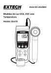
PH METER
Model : PH-208
Your purchase of this PH
METER marks a step
forward for you into the
field
of
precision
measurement.
Although
this PH METER is a
complex
and
delicate
instrument, its durable
structure will allow many
years of use if proper
operating techniques are
developed. Please read
the following instructions
carefully and always keep
this manual within easy
reach.
OPERATION MANUAL
TABLE OF CONTENTS
1.
FEATURES............................................................ 1
2. SPECIFICATIONS................................................... 2
3. FRONT PANEL DESCRIPTION.................................. 4
4. PH CALIBRATING PROCEDURE................................6
4-1 Calibrating Consideration...................................6
4-2 Requiring Equipment for calibration................... 6
4-3 Two Points Calibration...................................... 6
4-4 Signal Point Calibration..................................... 8
4-5 Others............................................................. 9
5. PH TEMPERATURE COMPENSATION........................ 10
5-1 Manual temperature compensation.................... 10
5-2 Automatic temperature compensation................14
6. MEASURING PROCEDURE....................................... 14
6-1 PH Measurement..............................................14
6-2 mV Measurement............................................. 15
6-3 Temp. Measurement.........................................15
7. AUTO POWER DISABLE.......................................... 18
8. RS232 PC SERIAL INTERFACE.................................18
9. BATTERY REPLACEMENT........................................ 20
10. OPTIONAL PROBES & ACCESSORIES....................... 20
;
1. FEATURES
* Professional PH/mV METER.
PH range : 0 to 14 PH x 0.01 PH.
mV range : -1999 mV to 1999 mV.
* The instrument is with mV ( millivolt ) function for
mV measurement ( cooperate with optional ORP probe
to be a professional ORP meter)
* Wide manual temperature compensation adjustment
can be easily operated by push button on the front panel.
* Optional ATC (Automatic Temp. Compensation) probe is
available for PH measurement.
* Microprocessor circuit assures high accuracy and reliable
performance.
* Large LCD, dual function display.
* Records Maximum and Minimum readings with recall.
* Data hold.
* Auto shut off saves battery life.
* Powered by 006P DC 9V battery.
* RS 232 computer serial interface.
* ℃ or ℉ can be converted by push button on the front panel.
* PH calibration is easily to be done by push button on the
front panel.
* Using the durable, long-lasting components and a strong
lightweight ABS-plastic housing case.
* PH function with high input impedance avoids measuring
error.
* Wide applications: water conditioning, aquariums, beverage,
fish hatcheries, food processing, photography, laboratory,
paper industry, plating industry, quality control, school &
college.
1
2. SPECIFICATIONS
2-1 General Specifications
Circuit
Display
Measurement
Custom one-chip of microprocessor LSI
circuit.
51 mm x 32 mm, dual function LCD display,
15 mm ( 0.6" ) digit size.
PH
0 to 14 PH
mV
-1999 mV to 1999 mV
10^12 ohm
Input
Impedance
Temperature
Manual
Compensation
for pH
Automatic
measurement ( ATC )
pH
Calibration
Data hold
Memory
Recall
Power off
Data Output
Overload
indication
PH
Electrode
0 to 100 ℃, be adjusted by
push button on front panel.
With the optional TEMP.
probe ( TP-07 )
0 to 65 ℃.
PH7, PH4, and PH10, 3 points calibration
ensure the best linearity and accuracy.
Hold the current reading value on the display.
Maximum and Minimum reading values can
be saved and retrieved by record function.
Auto shut off saves battery life, or manual
off by push button.
RS 232 computer serial interface.
"- - - -" symbol on the display.
Optional,
Any PH electrode with BNC connector.
Operating
0 ℃ to 50 ℃(32 ℉ to 122 ℉).
Temperature
2
Operating
Humidity
Max. 80% RH.
Sampling Time Approx. 0.8 second.
Power Supply 006P DC 9V battery
( Alkaline or Heavy duty type ).
Power Current Approx. DC 7 mA.
Weight
250 g/0.55 LB ( battery included ).
Size ( meter ) 195 x 68 x 30 mm ( 7.6 x 2.6 x 1.2 inch ).
Standard
Instruction manual...........1 PC.
Accessories
Optional
Probes &
Accessories
PH electrodes :
* General purpose PH electrode, PE-03
* General purpose PH electrode, PE-11
* Professional PH electrode, PE-01
* Spear tip PH electrode, PE-04HD, PE-06HD
(Ref. page 20) ATC temp. probe, TP-07
PH electrodes + Temp. Probe, PE-03K7
ORP electrode, ORP-14
Hard carrying case, CA-06
RS232 cable, UPCB-02
RS232 cable, USB-01
Application Software, SW-U801-WIN
2-2 Electrical Specifications (23 ± 5 ℃)
Measurement Range
PH
mV
Resolution Accuracy
0 to 14 PH
0 to 1999 mV
0.01 PH
1 mV
± (0.02 PH + 2 d)
± (0.5% + 2 d)
* PH accuracy is based on calibrated meter only.
* Specification tests under the environment RF Field Strength
less than 3 V/M & frequency less than 30 MHz only.
3
3. FRONT PANEL DESCRIPTION
Fig. 1
4
Fig. 2
3-1
3-2
3-3
3-4
3-5
3-6
3-7
3-8
3-9
3-10
3-11
3-12
3-13
3-14
3-15
Fig. 3
Display
Power Button
REC. Button
Hold Button
℃,℉ Button/Up Button
PH/mV Button/Left Button
TEMP. C Button
CAL Button/Down Button
Battery Compartment/Cover
PH BNC Input Socket
ATC Probe Input Socket
RS-232 Out Terminal
Stand
PH 7 VR
PH 4/PH 10 VR
5
4. PH CALIBRATION PROCEDURE
4-1 Calibration Consideration
The most ideal PH ELECTRODE generates 0 mV at PH
7.00 ( 177.4 mV at PH 4 ) and PH-208 has been always
calibrated with signals which simulate the most ideal PH
ELECTRODE ( based on 25℃ ambient environment ).
However not every PH ELECTRODE is as accurate as the
most ideal one, so calibration procedures are necessary
to be done before the first time measurement. In
addition to the first time measurement, users are also
recommended to execute the calibration procedures to
ensure the high accuracy measurement.
4-2 Required Equipment for Calibration
1) PH ELECTRODE ( optional ).
2) PH buffer solutions ( optional ).
4-3 Two Points Calibration Procedure
1) Power on the instrument by pressing the " Power
Button " ( 3-2, Fig. 1 ).
2) Press the " PH/mV Button " ( 3-6, Fig. 1 ) to let meter be
operated under the PH function with a " PH " symbol on the
display.
3) Adjust the " Temperature Compensation Value " to make
it same as the temperature value of the pH buffer
solution.
Manual temperature compensation value adjustment
procedure, please refer to 5-1 (Page 10).
Automatic temperature compensation value adjustment
procedure, please refer to 5-2 (Page 14).
6
4) PH 7 calibration
Connect the PH ELECTRODE with the " BNC socket "
( 3-10, Fig. 1 ) and immerse the electrode in the PH7
buffer solution.
Press the " CAL Button " ( 3-8, Fig. 1 ) then the upper
display shows texts of " CAL " and the lower display
shows the default calibration value.
CAL
7.00
* The texts " CAL " will flash for around 5 seconds.
After that, the meter calibrates itself automatically.
The upper display will show the calibrated value,
the lower display will show the temperature value.
7.00
25.0
5) PH 4 or PH 10 calibration
Rinse the electrode with distilled water.
Immerse the electrode in the PH4 buffer solution ( or PH10
buffer solution ).
Press the " CAL Button " ( 3-8, Fig. 1 ) then the upper
display shows texts of " CAL " and the lower display
shows the default calibration value.
7
CAL
4.00
* The texts " CAL " will flash for around 5 seconds.
After that, the meter calibrate itself automatically.
The upper display will show the calibrated value,
the lower display will show the temperature value.
4.00
25.0
6) Rinse the electrode with distilled water again.
7) Repeat above (4) to (5) procedures two times at least.
8) The instrument and electrode are now finished the
" TWO POINTS CALIBRATION " & ready for the
measurement.
4-4 Signal Point Calibration
If PH4 and PH10 buffer solution are not available, single
point (PH7) calibration can be executed from procedures
of 4-3 (1) to (4). However for more accurate measuring
result and linearity, two points calibration is always
recommended.
8
4-5 Others
Above calibration procedures effect only when reading value
within 1 PH of the calibration point.
However if the reading value beyond
* 1 PH of PH 7 ( > PH8, < PH6 )
* 1 PH of PH 4 ( > PH5, < PH3 )
* 1 PH of PH 10 ( > PH11, < PH9 )
the calibration procedures are :
1) Connect the PH ELECTRODE to the " PH BNC Input
Socket " ( 3-10, Fig. 1 ).
2) Power on the instrument by pressing the " Power
Button " ( 3-2, Fig. 1 ).
3) Press the " PH/mV Button " ( 3-6, Fig. 1 ) to select
the PH function with a "PH" symbol on the display
4) Set the " Manual temperature compensation " value to 25 ℃
refer to 5-1 calibration procedures, page 10.
5) Place the electrode into the standard solution ( PH7, PH4 or
PH10 ) , then the instrument will have the PH value on the
display.
6) * For measuring the PH7 standard solution, adjust the
PH 7 VR ( 3-14, Fig. 3 ) until the display value
within PH6 to PH8.
* For measuring the PH4 standard solution, adjust the
PH 4 VR ( 3-15, Fig. 3 ) until the display value
within PH3 to PH5.
* For measuring the PH10 standard solution, adjust the
PH 10 VR ( 3-15, Fig. 3 ) until the display value
within PH9 to PH11.
7) The following calibration procedures will be same as 4-3
( page 6 ) and 4-4 ( page 8 ).
9
5. PH TEMPERATURE COMPENSATION
Enable the meter to gain high accuracy measuring results
from different kinds of solution, the temperature
compensation calibration procedures are necessary to
be executed.
Manual temperature compensation calibration procedures
please refer to 5-1 ( See below).
Automatic temperature compensation calibration procedures
please refer to 5-2 ( Page 14 ).
5-1 Manual temperature compensation procedures
Before the manual temperature compensation calibration
procedures, please make sure there are no ATC probe
( TP-07 ) in the " Optional Probe Input Socket"
( 3-11, Fig. 1 ).
1) Power on the instrument by pressing the " Power
Button " ( 3-2, Fig. 1 ).
2) Press the " PH/mV Button " ( 3-6, Fig. 1 ) to select
the PH function with a " PH " symbol on the display
3) " TEMP. C Button " ( 3-7, Fig. 1 ) is used to adjust the
following values :
a. Temperature compensation value
b. PH 4 Default calibration value
c. PH 7 Default calibration value
d. PH 10 Default calibration value
10
a. Adjust the temperature compensation value
* Press the " TEMP. C Button " ( 3-7, Fig. 1 ) first,
The upper display will show the measured PH values.
the lower display will show the manual temperature
compensation value.
PH
7.91
026.1 ℃
@ Use the " Left Button " ( 3-6, Fig. 1 ), " Up Button "
( 3-5, Fig. 1 ) and the " Down Button " ( 3-8, Fig. 1 ) to
adjust the manual temperature compensation value.
b. Adjust the PH 4 default calibration value
* When the manual temp. compensation values
be adjusted. Press the " TEMP. C Button "
( 3-7, Fig. 1 )once again to adjust the PH 4
default calibration value.
The upper display will show the values of " 4.00 " and
the lower display will show the " PH 4 default calibration
value ".
PH
4.00
04.03
11
@ Use the " Up Button " ( 3-5, Fig. 1 ) and the " Down
Button " ( 3-8, Fig. 1 ) to adjust the PH 4 default
calibration value.
@ The adjustment range of " PH4 default calibration value "
is limited within 4.00.20 PH
c. Adjust the PH 7 default value
* When the PH 4 default value be adjusted. Press
the " TEMP. C Button " ( 3-7, Fig. 1 ) once
again to adjust the PH 7 default calibration
value.
The upper display will show the values of " 7.00 " and
the lower display will show the " PH 7 default
calibration value ".
PH
7.00
07.12
@ Use the " Up Button " ( 3-5, Fig. 1 ) and the "
Down Button " ( 3-8, Fig. 1 ) to adjust the PH 7
default calibration value.
@ The adjustment range of " PH 7 default calibration
value " is limited within 7.00.20 PH.
d. Adjust the PH 10 Default Value
* When the PH 7 default calibration value be
adjusted. Press the " TEMP. C Button " ( 3-7,
Fig. 1 ) once again to adjust the PH 10 default
calibration value.
12
The upper display will show the values of " 10.00 " and
the lower display will show the " PH 10 default
calibration value ".
PH
10.00
10.02
@ Use the " Up Button " ( 3-5, Fig. 1 ) and the " Down
Button " ( 3-8, Fig. 1 ) to adjust the PH 10 default
calibration value.
@ The adjustment range of " PH10 default calibration
value " is limited within 10.00.20 PH
e. Finish the adjustment
* When the PH 10 default calibration value be
adjusted, press the " TEMP. C Button " ( 3-7,
Fig. 1 ) once again to finish the manual
temperature calibration procedures and return to
the measuring mode.
Consideration :
If you want to skip any procedures above, just press
" Temp. C Button " ( 3-7, Fig. 1 ).
Above PH default calibration values you set will
become the default value when you execute the PH
Calibration Procedure. It is very convenient for user
when PH 4.00, PH 7.00, and PH 10.00 buffer
solution are not available.
13
5-2 Automatic temperature compensation
1) Plug the " Optional ATC Temp. Probe, TP-07 "
into the " ATC Probe Input Socket " ( 3-11, Fig. 1 ).
2) Power on the instrument by pressing the " Power
Button " ( 3-2, Fig. 1 ).
3) Press the " PH/mV Button " ( 3-6, Fig. 1 ) to select
the PH function with a "PH" symbol on the display
4) Place the "Temp. Probe" into the solution, and then
temperature will be compensated automatically for PH
measurement.
6. MEASURING PROCEDURE
6-1 PH Measurement
Whenever the calibration procedures are recommended to
be done before PH measurement.
1) Connect the PH ELECTRODE to the " PH BNC Input
Socket " ( 3-10, Fig. 1 ).
2) Power on the instrument by pressing the " Power
Button " ( 3-2, Fig. 1 ).
3) Press the " PH/mV Button " ( 3-6, Fig. 1 ) to select
the PH function with a "PH" symbol on the display.
14
4) * If the operating is under the " Manual temperature
compensation ", then please refer to the above 5-1
calibration procedures.
* If the operating is under the " Automatic temperature
compensation ", then please refer to the above 5-2
calibration procedures.
5) Place the electrode into the solution, then the instrument
will have the PH value on the display.
6) After the measurement, please rinse the electrode with
distilled water.
6-2 mV Measurement
The instrument build in mV ( millivolt ) measurement
function, which enable you to make ion-selective, ORP
(oxidation-reduction potential), and other precise mV
measurements.
Press the " PH/mV Button " ( 3-6, Fig. 1 ) to select
the mV function with a " mV " symbol on the display.
6-3 Temp. Measurement
1) Plug the " Optional ATC Temp. Probe, TP-07 "
into the " Optional Probe Input Socket " ( 3-11, Fig. 1 ).
2) * If you intend to measure " ℃ ", then press the " ℃/ ℉
Button " ( 3-5, Fig. 1 ) and select the " ℃ " unit.
* If you intend to measure " ℉ ", then press the " ℃/ ℉
Button " ( 3-5, Fig. 1 ) and select the " ℉ " unit.
3) Place the " Temp. Probe " into the solution, and the
instrument will have the temperature value on the
display.
15
6-4 Data Hold
Press the " Hold Button " ( 3-4, Fig. 1 ) will hold the
measured value & the LCD will indicate a " HOLD " symbol
on the display during the measuring.
* Press the " Hold Button " again to exit the data hold
function.
6-5 Data Record ( Max., Min. reading )
* The data record function records the maximum and
minimum readings. Press the " REC. Button " ( 3-3, Fig. 1 )
to start the Data Record function and there will be a
" REC " symbol on the display.
* With the " REC " symbol on the display :
a) Press the " REC. Button " ( 3-3, Fig. 1 ) once, the
" REC Max " symbol along with the maximum value
will appear on the display.
If you intend to delete the maximum value, just press
the " Hold Button " ( 3-4, Fig. 1 ) for a while, then
the display will show the " REC " symbol only &
execute the memory function continuously.
b) Press the " REC. Button " ( 3-3, Fig. 1 ) again, the
" REC Min " symbol along with the minimum value
will appear on the display.
If you intend to delete the minimum value, just press
the " Hold Button " ( 3-4, Fig. 1 ) for a while, then
the display will show the " REC " symbol only &
execute the memory function continuously.
c) To exit the memory record function, just press the
" REC " button for 2 seconds at least. The display will
revert to the current reading.
16
6-6 Following are the block diagrams for quick
measuring procedures
Calibration
Power
ON
Set the
manual
temp.
values
Single point calibration
PH 7(CAL.)
Two points calibration
PH 7(CAL.) &
PH4 ( PH10, SLOPE)
or
plug
ATC probe
PH measuring procedures
Setting the Manual temp.
compensation values
on front panel
Power
ON
or
Automatic temperature
compensation by optional
ATC probe
M
E
A
S
U
R
E
M
E
N
T
Optional measuring procedures
DATA HOLD
MEMORY RECORD
Max., Min.
17
RS232 OUTPUT
Power management
AUTO POWER OFF
(Not available during
MANUAL POWER OFF
or
Memory Record Function)
7. AUTO POWER OFF DISABLE
The instrument has " Auto Power Off " function in
order to prolong battery life. The meter will shut
off automatically if none of the buttons are pressed
in approx. 10 min.
To disable this function, select the memory record
function during the measurement by pressing the
" REC. Button " ( 3-3, Fig. 1 ).
8. RS232 PC SERIAL INTERFACE
The instrument features RS232 output via
3.5 mm Terminal ( 3-12, Fig. 3 ).
The signals output is a 16 digits data stream which
can be utilized for user's specific application.
A RS232 lead with the following connection will
be required to link the instrument with the PC
serial interface.
18
Meter
(3.5 mm jack plug)
PC
(9W 'D" Connector)
Center Pin...................................... Pin 4
Ground/shield.................................... Pin 2
Pin 5
2.2 K
resistor
The 16 digits data stream will be displayed in the
following format :
D15 D14 D13 D12 D11 D10 D9 D8 D7 D6 D5 D4 D3 D2 D1 D0
Each digit indicates the following status :
D15
D14
D13
D8 to D1
Start Word
4
When send the upper display data = 1
When send the lower display data = 2
Annunciator for Display
℃ = 01
℉ = 02
PH = 05
mV = 18
mS = 14
PPM = 19
O2= 06
mg/L = 07
Polarity
0 = Positive
1 = Negative
Decimal Point(DP), position from right to the left
0 = No DP, 1= 1 DP, 2 = 2 DP, 3 = 3 DP
Display reading, D8 = MSD, D1 = LSD
D0
End Word
D12, D11
D10
D9
For example :
If the display reading is 1234, then D8 to D1 is :
00001234
19
RS232 setting
Baud rate
Parity
Data bit no.
Stop bit
9600
No parity
8 Data bits
1 Stop bit
9. BATTERY REPLACEMENT
1) When the left corner of LCD display show "
", it
is necessary to replace the battery. However, in-spec.
measurement may still be made for several hours after
low battery indicator appears.
2) Slide the " Battery Cover " (3-14, Fig. 1) away from the
instrument and remove the battery.
3) Replace with 9V battery ( Alkaline or Heavy duty type )
and reinstate the cover.
4) Make sure the battery cover is secured after changing the
battery.
10. OPTIONAL PROBES & ACCESSORIES
ATC
PROBE
Model : TP-07
* ATC (Automatic Temperature
Compensation ) Probe for PH
function.
Measurement
Range
℃
0 ℃ to 65 ℃
℉
32℉ to 149 ℉
CARRYING CASE
CA-06
Hard carrying case
ORP ELECTRODE
Model :
ORP-14
Select to the mV function, plug the
ORP electrode into the BNC socket to
become a professional ORP
(oxidation-reduction potential) Meter.
20
PH ELECTRODE
Model : PE-03
PH ELECTRODE
Model : PE-11
PH ELECTRODE
Model : PE-01
SPEAR TIP
PH ELECTRODE
Model : PE-04HD
PE-06HD
General purpose, laboratory &
field usage. 12.3 mm dia. x 160 mm.
Epoxy body, 1 - 13 pH.
General purpose, laboratory &
field usage. 10 mm dia. x 130 mm.
Epoxy body, 1 - 13 pH.
(0 - 14 pH typical)
Professional, laboratory &
field usage. 9.5 mm dia. x 130 mm.
Epoxy body, 0 - 14 pH.
The " Spear Tip pH electrode " is
perfect for those pH measurements in
applications where sample piercing is
required. Meat, sausage and cheese
are ideal applications. The electrode
features a very durable glass
measuring spear packaged in a
rugged virtually unbreakable epoxy
body.
Range : 0 to 14 pH ( PE-04HD)
Range : 1 to 13 pH ( PE-06HD)
BUFFER SOLUTION
PH-07
BUFFER SOLUTION
PH-04
PH
for
PH
for
7.00 standard buffer solution.
calibration purpose.
4.00 standard buffer solution.
calibration purpose.
RS232 cable
UPCB-02
RS232 cable for connecting between
the meter & the computer.
SOFTWARE
SW-U801-WIN
Windows version application software
applies as the performance of data
logging system & data recorder...
21
0604-PH208