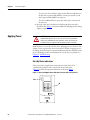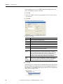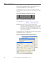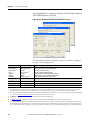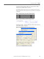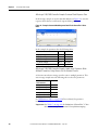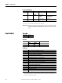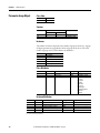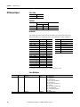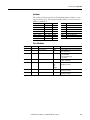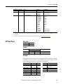
1
User Manual
Dual-Port EtherNet/IP Communication Adapter
Catalog Number 20-COMM-ER
Important User Information
Solid state equipment has operational characteristics differing from those of electromechanical equipment. Safety
Guidelines for the Application, Installation and Maintenance of Solid State Controls (Publication SGI-1.1 available from
your local Rockwell Automation sales office or online at http://www.rockwellautomation.com/literature) describes
some important differences between solid state equipment and hard-wired electromechanical devices. Because of this
difference, and also because of the wide variety of uses for solid state equipment, all persons responsible for applying
this equipment must satisfy themselves that each intended application of this equipment is acceptable.
In no event will Rockwell Automation, Inc. be responsible or liable for indirect or consequential damages resulting
from the use or application of this equipment.
The examples and diagrams in this manual are included solely for illustrative purposes. Because of the many variables
and requirements associated with any particular installation, Rockwell Automation, Inc. cannot assume responsibility
or liability for actual use based on the examples and diagrams.
No patent liability is assumed by Rockwell Automation, Inc. with respect to use of information, circuits, equipment, or
software described in this manual.
Reproduction of the contents of this manual, in whole or in part, without written permission of Rockwell Automation,
Inc. is prohibited.
Throughout this manual, when necessary we use notes to make you aware of safety considerations.
WARNING: Identifies information about practices or circumstances that can
cause an explosion in a hazardous environment, which may lead to personal
injury or death, property damage, or economic loss.
Important: Identifies information that is critical for successful application and understanding of the product.
ATTENTION: Identifies information about practices or circumstances that can
lead to personal injury or death, property damage, or economic loss. Attentions
help you identify a hazard, avoid a hazard, and recognize the consequences.
Shock Hazard labels may be located on or inside the equipment (e.g.,
drive or motor) to alert people that dangerous voltage may be present.
Burn Hazard labels may be located on or inside the equipment (e.g.,
drive or motor) to alert people that surfaces may be at dangerous
temperatures.
Allen-Bradley, Rockwell Software, and TechConnect are trademarks of Rockwell Automation, Inc.
Trademarks not belonging to Rockwell Automation are property of their respective companies.
2
Rockwell Automation Publication 20COMM-UM015B-EN-P - June 2013
Table of Contents
Preface
About This Manual . . . . . . . . . . . . . . . . . . . . . . . . . . . . . . . . . . . . . . . . . . . . . . .
Conventions Used in This Manual . . . . . . . . . . . . . . . . . . . . . . . . . . . . . . . . .
Rockwell Automation Support . . . . . . . . . . . . . . . . . . . . . . . . . . . . . . . . . . . . .
Additional Resources . . . . . . . . . . . . . . . . . . . . . . . . . . . . . . . . . . . . . . . . . . . . . .
7
7
8
8
Chapter 1
Getting Started
Components . . . . . . . . . . . . . . . . . . . . . . . . . . . . . . . . . . . . . . . . . . . . . . . . . . . . .
Features . . . . . . . . . . . . . . . . . . . . . . . . . . . . . . . . . . . . . . . . . . . . . . . . . . . . . . . . .
Compatible Products . . . . . . . . . . . . . . . . . . . . . . . . . . . . . . . . . . . . . . . . . . . . .
Required Equipment . . . . . . . . . . . . . . . . . . . . . . . . . . . . . . . . . . . . . . . . . . . . .
Equipment Shipped with the Adapter . . . . . . . . . . . . . . . . . . . . . . . . . .
User-Supplied Equipment . . . . . . . . . . . . . . . . . . . . . . . . . . . . . . . . . . . . .
Safety Precautions . . . . . . . . . . . . . . . . . . . . . . . . . . . . . . . . . . . . . . . . . . . . . . . .
Quick Start . . . . . . . . . . . . . . . . . . . . . . . . . . . . . . . . . . . . . . . . . . . . . . . . . . . . . .
11
12
13
13
13
13
15
16
Chapter 2
Installing the Adapter
EMC Conformance . . . . . . . . . . . . . . . . . . . . . . . . . . . . . . . . . . . . . . . . . . . . . .
Preparing for an Installation. . . . . . . . . . . . . . . . . . . . . . . . . . . . . . . . . . . . . . .
Setting the Web Pages Switch . . . . . . . . . . . . . . . . . . . . . . . . . . . . . . . . . . . . .
Connecting the Adapter to the Drive or SMC . . . . . . . . . . . . . . . . . . . . . .
Connecting the Adapter to the Network . . . . . . . . . . . . . . . . . . . . . . . . . . .
Applying Power . . . . . . . . . . . . . . . . . . . . . . . . . . . . . . . . . . . . . . . . . . . . . . . . . .
Start-Up Status Indications. . . . . . . . . . . . . . . . . . . . . . . . . . . . . . . . . . . .
Configuring and Verifying Key Drive Parameters. . . . . . . . . . . . . . . .
Commissioning the Adapter . . . . . . . . . . . . . . . . . . . . . . . . . . . . . . . . . . . . . .
17
18
19
20
23
24
24
26
26
Chapter 3
Configuring the Adapter
Configuration Tools. . . . . . . . . . . . . . . . . . . . . . . . . . . . . . . . . . . . . . . . . . . . . .
Using the PowerFlex 7-Class HIM. . . . . . . . . . . . . . . . . . . . . . . . . . . . . . . . .
Using an LED HIM . . . . . . . . . . . . . . . . . . . . . . . . . . . . . . . . . . . . . . . . . .
Using an LCD HIM . . . . . . . . . . . . . . . . . . . . . . . . . . . . . . . . . . . . . . . . .
Using BOOTP. . . . . . . . . . . . . . . . . . . . . . . . . . . . . . . . . . . . . . . . . . . . . . . . . . .
Configure the Adapter Using a BOOTP Server . . . . . . . . . . . . . . . . .
Setting the IP Address, Subnet Mask, and Gateway Address. . . . . . . . . .
Disable the BOOTP Feature . . . . . . . . . . . . . . . . . . . . . . . . . . . . . . . . . .
Set an IP Address Using Parameters . . . . . . . . . . . . . . . . . . . . . . . . . . . .
Set a Subnet Mask Using Parameters . . . . . . . . . . . . . . . . . . . . . . . . . . .
Set a Gateway Address Using Parameters . . . . . . . . . . . . . . . . . . . . . . .
Setting the Data Rate . . . . . . . . . . . . . . . . . . . . . . . . . . . . . . . . . . . . . . . . . . . . .
Setting the I/O Configuration. . . . . . . . . . . . . . . . . . . . . . . . . . . . . . . . . . . . .
Selecting Master-Slave or Peer-to-Peer . . . . . . . . . . . . . . . . . . . . . . . . . . . . .
Setting a Master-Slave Hierarchy 36
Setting the Adapter to Transmit Peer-to-Peer Data . . . . . . . . . . . . .
Setting the Adapter to Receive Peer-to-Peer Data. . . . . . . . . . . . . . . .
Setting the Reference Adjustment . . . . . . . . . . . . . . . . . . . . . . . . . . . . . . . . .
Setting a Fault Action. . . . . . . . . . . . . . . . . . . . . . . . . . . . . . . . . . . . . . . . . . . . .
Rockwell Automation Publication 20COMM-UM015B-EN-P – June 2013
27
28
28
28
29
29
32
32
32
33
33
34
35
36
37
38
41
41
3
Table of Contents
Changing the Fault Action . . . . . . . . . . . . . . . . . . . . . . . . . . . . . . . . . . . .
Setting the Fault Configuration Parameters. . . . . . . . . . . . . . . . . . . . .
Setting Web Access Control . . . . . . . . . . . . . . . . . . . . . . . . . . . . . . . . . . . . . .
Resetting the Adapter . . . . . . . . . . . . . . . . . . . . . . . . . . . . . . . . . . . . . . . . . . . .
Viewing the Adapter Status Using Parameters . . . . . . . . . . . . . . . . . . . . . .
Updating the Adapter Firmware. . . . . . . . . . . . . . . . . . . . . . . . . . . . . . . . . . .
42
42
42
43
44
44
Chapter 4
Configuring the I/O
Using RSLinx Classic Software . . . . . . . . . . . . . . . . . . . . . . . . . . . . . . . . . . . . 47
ControlLogix Controller Example . . . . . . . . . . . . . . . . . . . . . . . . . . . . . . . . . 48
Adding the Bridge to the I/O Configuration. . . . . . . . . . . . . . . . . . . . 49
Using RSLogix 5000 Device Add-on Profiles, Version 16.00 or Later
51
Using the RSLogix 5000 Classic Profile, Versions 13.00…15.00. . . 60
Using the RSLogix 5000 Generic Profile, All Versions . . . . . . . . . . . 62
Limitations Using a MicroLogix 1100/1400 Controller . . . . . . . . . . . . . 68
MicroLogix 1100/1400 Controller Example. . . . . . . . . . . . . . . . . . . . . . . . 68
Configuring Parameters for Network I/O . . . . . . . . . . . . . . . . . . . . . . 69
Creating RSLogix 500 Project, Version 7.00 or Later . . . . . . . . . . . . 70
Chapter 5
Using the I/O
About I/O Messaging . . . . . . . . . . . . . . . . . . . . . . . . . . . . . . . . . . . . . . . . . . . . 79
Understanding the I/O Image . . . . . . . . . . . . . . . . . . . . . . . . . . . . . . . . . . . . . 80
ControlLogix Controller Image. . . . . . . . . . . . . . . . . . . . . . . . . . . . . . . . 80
MicroLogix 1100/1400 Controller Image . . . . . . . . . . . . . . . . . . . . . . 82
Using Logic Command/Status . . . . . . . . . . . . . . . . . . . . . . . . . . . . . . . . . . . . 84
Using Reference/Feedback . . . . . . . . . . . . . . . . . . . . . . . . . . . . . . . . . . . . . . . . 84
PowerFlex 7-Class Drives . . . . . . . . . . . . . . . . . . . . . . . . . . . . . . . . . . . . . 85
Using Datalinks . . . . . . . . . . . . . . . . . . . . . . . . . . . . . . . . . . . . . . . . . . . . . . . . . . 86
Rules for Using Datalinks . . . . . . . . . . . . . . . . . . . . . . . . . . . . . . . . . . . . . 86
Using 16-Bit Datalinks to Read/Write 32-Bit Parameters . . . . . . . . 86
Example Ladder Logic Program Information . . . . . . . . . . . . . . . . . . . . . . . 87
Functions of the Example Programs . . . . . . . . . . . . . . . . . . . . . . . . . . . . 87
Logic Command/Status Words. . . . . . . . . . . . . . . . . . . . . . . . . . . . . . . . 88
ControlLogix Controller Example . . . . . . . . . . . . . . . . . . . . . . . . . . . . . . . . . 88
Creating Ladder Logic Using the RSLogix 5000 Device Add-on
Profiles, Version 16.00 or Later . . . . . . . . . . . . . . . . . . . . . . . . . . . . . . . . 88
Creating Ladder Logic Using the RSLogix 5000 Classic Profile,
Versions 1300…15.00 . . . . . . . . . . . . . . . . . . . . . . . . . . . . . . . . . . . . . . . . . 89
Creating Ladder Logic Using the RSLogix 5000 Generic Profile, All
Versions . . . . . . . . . . . . . . . . . . . . . . . . . . . . . . . . . . . . . . . . . . . . . . . . . . . . . 90
MicroLogix 1100/1400 Controller Example. . . . . . . . . . . . . . . . . . . . . . . . 96
Drive and Adapter Parameter Settings. . . . . . . . . . . . . . . . . . . . . . . . . . 96
Understanding Controller Data Table Addresses. . . . . . . . . . . . . . . . 97
Chapter 6
4
Rockwell Automation Publication 20COMM-UM015B-EN-P - June 2013
Table of Contents
Using Explicit Messaging
About Explicit Messaging . . . . . . . . . . . . . . . . . . . . . . . . . . . . . . . . . . . . . . . . 106
Performing Explicit Messages . . . . . . . . . . . . . . . . . . . . . . . . . . . . . . . . . . . . 106
ControlLogix Controller Examples . . . . . . . . . . . . . . . . . . . . . . . . . . . . . . . 108
Explicit Messaging Using RSLogix 5000 Software, Version 15.00 or
Later . . . . . . . . . . . . . . . . . . . . . . . . . . . . . . . . . . . . . . . . . . . . . . . . . . . . . . . 108
Explicit Messaging Using RSLogix 5000 Software, All Versions. . 121
MicroLogix 1100/1400 Controller Examples . . . . . . . . . . . . . . . . . . . . . . 124
MicroLogix 1100/1400 Controller Explicit Messaging Using the
Read/Write Parameter Service. . . . . . . . . . . . . . . . . . . . . . . . . . . . . . . . 125
MicroLogix 1100/1400 Controller Explicit Messaging Using the
Generic Get/Set Attribute Service . . . . . . . . . . . . . . . . . . . . . . . . . . . . 130
Chapter 7
Troubleshooting
Understanding the Status Indicators . . . . . . . . . . . . . . . . . . . . . . . . . . . . . .
Port Status Indicator . . . . . . . . . . . . . . . . . . . . . . . . . . . . . . . . . . . . . . . . . . . .
Network Status Indicator . . . . . . . . . . . . . . . . . . . . . . . . . . . . . . . . . . . . . . . .
Link (LS1, LS2) Status Indicator . . . . . . . . . . . . . . . . . . . . . . . . . . . . . . . . .
NET A Status Indicator . . . . . . . . . . . . . . . . . . . . . . . . . . . . . . . . . . . . . . . . .
Hardware Reset via Node Switches . . . . . . . . . . . . . . . . . . . . . . . . . . . . . . .
Viewing Adapter Diagnostic Items. . . . . . . . . . . . . . . . . . . . . . . . . . . . . . . .
Viewing and Clearing Events . . . . . . . . . . . . . . . . . . . . . . . . . . . . . . . . . . . . .
143
144
145
145
145
146
146
149
Chapter 8
Viewing the Adapter Web Pages
Accessing the Adapter Web Home Page. . . . . . . . . . . . . . . . . . . . . . . . . . .
Viewing the Web Pages . . . . . . . . . . . . . . . . . . . . . . . . . . . . . . . . . . . . . . . . . .
Title Bar on Adapter Web Pages . . . . . . . . . . . . . . . . . . . . . . . . . . . . . .
Navigation Pane on Adapter Web Pages . . . . . . . . . . . . . . . . . . . . . . .
Process Display Home Page . . . . . . . . . . . . . . . . . . . . . . . . . . . . . . . . . . . . . .
Browse DPI Device Folder . . . . . . . . . . . . . . . . . . . . . . . . . . . . . . . . . . . . . . .
Diagnostics Web Page . . . . . . . . . . . . . . . . . . . . . . . . . . . . . . . . . . . . . . . . . . .
Diagnostic Overview link . . . . . . . . . . . . . . . . . . . . . . . . . . . . . . . . . . . .
Network Setting Link. . . . . . . . . . . . . . . . . . . . . . . . . . . . . . . . . . . . . . . .
EtherNet/IP Statistics Link . . . . . . . . . . . . . . . . . . . . . . . . . . . . . . . . . .
Ring Statistics link . . . . . . . . . . . . . . . . . . . . . . . . . . . . . . . . . . . . . . . . . . .
Crash Display Link . . . . . . . . . . . . . . . . . . . . . . . . . . . . . . . . . . . . . . . . . .
Heap Statistics Display link . . . . . . . . . . . . . . . . . . . . . . . . . . . . . . . . . .
Administrative Web Pages . . . . . . . . . . . . . . . . . . . . . . . . . . . . . . . . . . . . . . .
Device Identity Link . . . . . . . . . . . . . . . . . . . . . . . . . . . . . . . . . . . . . . . .
Network Configuration Link . . . . . . . . . . . . . . . . . . . . . . . . . . . . . . . .
Email Configuration Link . . . . . . . . . . . . . . . . . . . . . . . . . . . . . . . . . . . .
Password Configuration . . . . . . . . . . . . . . . . . . . . . . . . . . . . . . . . . . . . . . . . .
153
153
154
155
156
156
157
157
158
159
159
160
160
160
161
161
162
165
Chapter 9
Using the Adapter in a DPI External
Comms Kit (20-XCOMM-DC-BASE)
Installing the Adapter . . . . . . . . . . . . . . . . . . . . . . . . . . . . . . . . . . . . . . . . . . . 167
Rockwell Automation Publication 20COMM-UM015B-EN-P - June 2013
5
Table of Contents
Appendix A
Specifications
Communications. . . . . . . . . . . . . . . . . . . . . . . . . . . . . . . . . . . . . . . . . . . . . . . .
Electrical . . . . . . . . . . . . . . . . . . . . . . . . . . . . . . . . . . . . . . . . . . . . . . . . . . . . . . .
Mechanical . . . . . . . . . . . . . . . . . . . . . . . . . . . . . . . . . . . . . . . . . . . . . . . . . . . . .
Environmental . . . . . . . . . . . . . . . . . . . . . . . . . . . . . . . . . . . . . . . . . . . . . . . . . .
Regulatory Compliance . . . . . . . . . . . . . . . . . . . . . . . . . . . . . . . . . . . . . . . . . .
169
169
170
170
170
Appendix B
Adapter Parameters
About Parameter Numbers. . . . . . . . . . . . . . . . . . . . . . . . . . . . . . . . . . . . . . . 171
Parameter List . . . . . . . . . . . . . . . . . . . . . . . . . . . . . . . . . . . . . . . . . . . . . . . . . . 171
Appendix C
EtherNet/IP Objects
Supported Data Types . . . . . . . . . . . . . . . . . . . . . . . . . . . . . . . . . . . . . . .
Identity Object. . . . . . . . . . . . . . . . . . . . . . . . . . . . . . . . . . . . . . . . . . . . . . . . . .
Assembly Object . . . . . . . . . . . . . . . . . . . . . . . . . . . . . . . . . . . . . . . . . . . . . . . .
Register Object. . . . . . . . . . . . . . . . . . . . . . . . . . . . . . . . . . . . . . . . . . . . . . . . . .
Parameter Object . . . . . . . . . . . . . . . . . . . . . . . . . . . . . . . . . . . . . . . . . . . . . . .
Parameter Group Object. . . . . . . . . . . . . . . . . . . . . . . . . . . . . . . . . . . . . . . . .
Device Level Ring Object . . . . . . . . . . . . . . . . . . . . . . . . . . . . . . . . . . . . . . . .
Quality of Service Object . . . . . . . . . . . . . . . . . . . . . . . . . . . . . . . . . . . . . . . .
PCCC Object . . . . . . . . . . . . . . . . . . . . . . . . . . . . . . . . . . . . . . . . . . . . . . . . . .
DPI Device Object . . . . . . . . . . . . . . . . . . . . . . . . . . . . . . . . . . . . . . . . . . . . . .
DPI Parameter Object . . . . . . . . . . . . . . . . . . . . . . . . . . . . . . . . . . . . . . . . . . .
DPI Fault Object. . . . . . . . . . . . . . . . . . . . . . . . . . . . . . . . . . . . . . . . . . . . . . . .
DPI Alarm Object. . . . . . . . . . . . . . . . . . . . . . . . . . . . . . . . . . . . . . . . . . . . . . .
DPI Diagnostic Object . . . . . . . . . . . . . . . . . . . . . . . . . . . . . . . . . . . . . . . . . .
DPI Time Object . . . . . . . . . . . . . . . . . . . . . . . . . . . . . . . . . . . . . . . . . . . . . . .
TCP/IP Interface Object . . . . . . . . . . . . . . . . . . . . . . . . . . . . . . . . . . . . . . . .
Ethernet Link Object . . . . . . . . . . . . . . . . . . . . . . . . . . . . . . . . . . . . . . . . . . . .
182
182
183
184
185
188
189
190
190
196
198
204
206
207
209
211
213
Appendix D
Logic Command/Status Words
PowerFlex 70/70EC, PowerFlex 700/700VC, and PowerFlex 700H
Drives . . . . . . . . . . . . . . . . . . . . . . . . . . . . . . . . . . . . . . . . . . . . . . . . . . . . . . . . . .
Logic Command Word . . . . . . . . . . . . . . . . . . . . . . . . . . . . . . . . . . . . . .
Logic Status Word. . . . . . . . . . . . . . . . . . . . . . . . . . . . . . . . . . . . . . . . . . .
PowerFlex 700S Drives . . . . . . . . . . . . . . . . . . . . . . . . . . . . . . . . . . . . . . . . . .
Logic Command Word (Phase II Control) . . . . . . . . . . . . . . . . . . . .
Logic Status Word (Phase II Control) . . . . . . . . . . . . . . . . . . . . . . . .
SMC Flex Controllers /SMC-50 Controllers . . . . . . . . . . . . . . . . . . . . . .
Logic Status Word. . . . . . . . . . . . . . . . . . . . . . . . . . . . . . . . . . . . . . . . . . .
Logic Command Word (Control) . . . . . . . . . . . . . . . . . . . . . . . . . . . .
215
215
216
217
217
218
219
219
220
Glossary. . . . . . . . . . . . . . . . . . . . . . . . . . . . . . . . . . . . . . . . . . . . . . . . . . . . . . . . . 221
Index . . . . . . . . . . . . . . . . . . . . . . . . . . . . . . . . . . . . . . . . . . . . . . . . . . . . . . . . . . . 231
6
Rockwell Automation Publication 20COMM-UM015B-EN-P - June 2013
Preface
About This Manual
Topic
Page
Conventions Used in This Manual
7
Rockwell Automation Support
7
Additional Resources
8
This manual provides information about the adapter and using it with PowerFlex
7-Class (Architecture-Class) drives or Bulletin 150 SMC Soft Starters. The
adapter can be used with other products that support a DPI™ adapter, such as the
DPI External Comms Kit (20-XCOMM-DC-BASE). See the documentation
for your product for specific information about how it works with the adapter.
Conventions Used in This
Manual
The following conventions are used throughout this manual:
• Parameter names are shown in the format Parameter xx - [*]. The xx
represents the parameter number. The * represents the parameter name—
for example Parameter 01 - [DPI Port].
• Menu commands are shown in bold type face and follow the format
Menu > Command. For example, if you read ‘Select File > Open’, you
should click the File menu and then click the Open command.
• The firmware revision number (FRN) is displayed as FRN X.xxx, where
‘X’ is the major revision number and ‘xxx’ is the minor revision number.
• The screen images in this manual resulted from using the following
software:
– RSLinx® Classic software, version 2.51
– RSLogix 5000 software, version 16
Different versions of the software may have screens that vary in
appearance, and differences in procedures.
Rockwell Automation
Support
Rockwell Automation offers support services worldwide, with over 75 sales and
support offices, over 500 authorized distributors, and over 250 authorized
systems integrators located through the United States alone. In addition,
Rockwell Automation representatives are in every major country in the world.
Local Product Support
Contact your local Rockwell Automation representative for the following:
• Sales and order support
• Product technical training
Rockwell Automation Publication 20COMM-UM015B-EN-P - June 2013
7
Preface
• Warranty support
• Support service agreements
Technical Product Assistance
For technical assistance, please review the information in Chapter 7,
Troubleshooting, first. If you still have problems, then access the Allen-Bradley
Technical Support website at www.ab.com/support/abdrives or contact
Rockwell Automation.
Additional Resources
These documents contain additional information concerning related products
from Rockwell Automation.
Resource
Description
Industrial Automation wiring and grounding guidelines, publication 1770-4.1
Provides general guidelines for installing a Rockwell
Automation industrial system.
Product certifications website, http://www.ab.com
Provides declarations of conformity, certificates, and
other certification details.
Industrial Security Best Practices, publication SECUR-AT001
Provides further information and guidelines on product
and system security.
PowerFlex 7-Class DPI (Drive Peripheral Interface) Network Communication Adapter Installation Information on the installation of PowerFlex®
20-COMM-x Network Communication Adapters.
Instructions, publication 20COMM-IN004
EtherNet/IP Media Planning and Installation Manual, ODVA publication 148 (1)
EtherNet/IP Network Infrastructure Guidelines, ODVA publication 35 (1)
Information on the planning, installation, and techniques
used to implement an EtherNet/IP network.
Ethernet Design Considerations Reference Manual, publication ENET-RM002
Connected Components Workbench website
http://www.ab.com/support/abdrives/webupdate/software.html, and online help
Information on the Connected Components
Workbench™ software tool—and includes a link for free
software download.
PowerFlex 20-HIM-A3/-A5/-C3S/-C5S HIM Quick Reference, publication 20HIM-QR001
Information on the use of the PowerFlex 20-HIM-A3, 20HIM-A5, 20-HIM-C3S, and 20-HIM-C5S HIMs.
PowerFlex 20-HIM-A6/-C6S HIM (Human Interface Module) User Manual, publication 20HIMUM001
Information on the installation and use of the PowerFlex
20-HIM-A6 and 20-HIM-C6S HIMs.
PowerFlex 70 User Manual, publication 20A-UM001
PowerFlex 70/700 Reference Manual, publication PFLEX-RM001
PowerFlex 70EC/700VC Reference Manual, publication PFLEX-RM004
Information on installing, programming, and technical
data of PowerFlex 70 and PowerFlex 70EC drives.
PowerFlex 700 Series A User Manual, publication 20B-UM001
PowerFlex 700 Series B User Manual, publication 20B-UM002
PowerFlex 70/700 Reference Manual, publication PFLEX-RM001
PowerFlex 70EC/700VC Reference Manual, publication PFLEX-RM004
Information on installing, programming, and technical
data of PowerFlex 700/700VC Series A and PowerFlex
700VC Series B drives.
PowerFlex 700H Installation Instructions, publication PFLEX-IN006
PowerFlex 700H Programming Manual, publication 20C-PM001
Information on installing, programming, and technical
data of PowerFlex 700H drives.
8
Rockwell Automation Publication 20COMM-UM015B-EN-P - June 2013
Preface
Resource
Description
PowerFlex 700S w/Phase I Control Installation Manual (Frames 1…6), publication 20D-IN024
PowerFlex 700S w/Phase I Control Installation Manual (Frames 9 and 10), publication PFLEXIN006
PowerFlex 700S w/Phase I Control User Manual (All Frame Sizes), publication 20D-UM001
PowerFlex 700S w/Phase I Control Reference Manual, publication PFLEX-RM002
PowerFlex 700S w/Phase II Control Installation Manual (Frames 1…6), publication 20D-IN024
PowerFlex 700S w/Phase II Control Installation Manual (Frames 9…14), publication PFLEXIN006
PowerFlex 700S w/Phase II Control Programming Manual (All Frame Sizes), publication 20DPM001
PowerFlex 700S w/Phase II Control Reference Manual, publication PFLEX-RM003
Information on installing, programming, and technical
data of PowerFlex 700S drives.
PowerFlex 700L User Manual, publication 20L-UM001
Information on installing, programming, and technical
data of PowerFlex 700L Liquid-Cooled AC drives.
SMC Flex Smart Motor Controller User Manual, publication 150-UM008
Information on installing, programming, and technical
data of SMC Flex State Smart Motor Controller.
SMC-50 Solid-State Smart Motor Controller User Manual, publication 150-UM011
Information on installing, programming, and technical
data of SMC-50 Solid-State Smart Motor Controller.
PowerFlex Digital DC Drive User Manual, publication 20P-UM001
Information on installing, programming, and technical
data of PowerFlex Digital DC drives.
Getting Results with RSLinx Guide, publication LINX-GR001and online help (1)
Information on using RSLinx Classic software.
RSLogix Emulate 5/500 Getting Results Guide, publication EMULAT-GR002 and online help
Information on how to install and navigate the RSLogix
Emulate software for ladder logic programming with
Allen-Bradley® PLC-5® and SLC™ 500 processors.
RSLogix 500 Getting Results Guide, publication LG500-GR002 and online help (1)
Information on using RSLogix 500 software tool.
RSLogix 5000 PIDE Autotuner Getting Results Guide, publication PIDE-GR001 and online help Information on using RSLogix 5000 software tool.
(1)
EtherNet/IP Modules in Logix5000 Control Systems User Manual, publication ENET-UM001
Information on using the ControlLogix® 1756-ENBT or
1756-EN2T EtherNet/IP communication modules with
your Logix5000 controller and communicating with
various devices on the EtherNet/IP network.
Enhanced and Ethernet PLC-5 Programmable Controllers User Manual, publication 1785UM012
Information to help design, operate and maintain an
Enhanced and Ethernet PLC-5 programmable controller
system.
MicroLogix 1100 Programmable Controllers User Manual, publication 1763-UM001
MicroLogix 1400 Programmable Controllers User Manual, publication 1766-UM001
Information to install, wire, and troubleshoot the
MicroLogix™ 1100 and MicroLogix 1400 controllers
respectively.
Web Updates http://www.ab.com/support/abdrives/webupdate/
Flash Update Files, Product Help Files, Control Bar
Files, GSD Files, EDS File links, DriveTools SP / Drive
AOP Database Files, and other downloads to keep your
Allen-Bradley brand drive products up to date
(1)
Use this link to the ODVA EtherNet/IP library: http://odva.org/Home/ODVATECHNOLOGIES/EtherNetIP/EtherNetIPLibrary/tabid/76/Default.aspx
Documentation can be obtained online at http://
literature.rockwellautomation.com. To order paper copies of technical
documentation, contact your local Rockwell Automation distributor or sales
representative.
To find your local Rockwell Automation distributor or sales representative, visit
http://www.rockwellautomation.com/locations.
For information such as firmware updates or answers to drive-related questions,
go to the Drives Service & Support web site at http://www.ab.com/support/
abdrives and click on the Downloads or Knowledgebase link.
Rockwell Automation Publication 20COMM-UM015B-EN-P - June 2013
9
Preface
Notes:
10
Rockwell Automation Publication 20COMM-UM015B-EN-P - June 2013
Chapter
1
Getting Started
The adapter is intended for installation in a PowerFlex 7-Class drive or Bulletin
150 SMC soft starter and is used for network communication.
Topic
Page
Components
11
Features
12
Compatible Products
13
Required Equipment
13
Safety Precautions
15
Quick Start
16
Components
➊
➋
➎
➌
➍
Item
Part
Description
➊
Status Indicators
Four status indicators that indicate the status of the DPI, the
adapter, and network connection. See Chapter 7, Troubleshooting.
➋
DPI Connector
A 20-pin, single-row shrouded male header. An Internal Interface
cable is connected to this connector and a connector on the drive.
➌
Ethernet Connector
RJ-45 connector for the Ethernet network cable. The connector is
CAT-5 compliant to ensure reliable data transfer on 100Base-TX
Ethernet connections.
➍
Web Pages Switch
(SW4)
Enables or disables the adapter web pages. See Setting the Web
Pages Switch on page 19.
➎
Address/mode
switches
Set IP address or DHCP/BootP mode.
Rockwell Automation Publication 20COMM-UM015B-EN-P - July 2013
11
Chapter 1
Features
Getting Started
The features of the adapter include the following:
• Typical mounting in a PowerFlex 7-Class drive or SMC soft starter.
• Captive screws to secure and ground the adapter to the drive.
• Compatibility with various configuration tools to configure the adapter
and connected host drive, including the following tools:
– PowerFlex HIM (Human Interface Module) on the drive or SMC, if
available
– Connected Components Workbench software, version 1.02 or later
– DriveExplorer software, version 2.01 or later
– DriveExecutive software, version 3.01 or later
– RSLogix5000 version16 and later with Drives Add-on Profile version
4.05 and later
Additionally, you can use a BOOTP/DHCP server to configure the
network address for the adapter.
• Status indicators that report the status of the drive communications, the
adapter, and network. They are visible when the drive cover is open or closed.
• Parameter-configured I/O (Logic Command/Reference and up to four
pairs of Datalinks) to accommodate application requirements.
• Explicit Messaging support.
• Master-Slave or Peer-to-Peer hierarchy that can be configured to transmit
data to and from either a controller or another PowerFlex drive or SMC on
the network.
• User-defined fault actions to determine how the adapter and connected
PowerFlex drive respond to the following:
– I/O messaging communication disruptions (Comm Flt Action)
– Controllers in idle mode (Idle Flt Action)
• Web pages, viewed by using a web browser, that show information about the
adapter, its connected host drive, and DPI devices connected to the drive.
• Configurable e-mail messaging to desired addresses when selected drive
faults occur and/or are cleared, and/or when the adapter takes a
communication or idle fault action.
• Access to any PowerFlex drive or SMC and its connected peripherals on
the network to which the adapter is connected.
• Device Level Ring (DLR) or Star Topology support with Quality of
Service (QoS) support.
12
Rockwell Automation Publication 20COMM-UM015B-EN-P - July 2013
Getting Started
Compatible Products
Chapter 1
At the time of publication, the adapter is compatible with the following products:
• PowerFlex 70/70EC drives
• PowerFlex 700L drives
• PowerFlex 700/700VC drives
• PowerFlex Digital DC drives
• PowerFlex 700H drives
• DPI External Comms Kit
• PowerFlex 700S drives
• SMC™-50
• PowerFlex 7000/7000-2 drives
• SMC™ Flex
Note: The adapter is not compatible with PowerFlex 750 series drives.
Required Equipment
Some of the equipment that is required for use with the adapter is shipped with
the adapter, but some you must supply yourself.
Equipment Shipped with the Adapter
When you unpack the adapter, verify that the package includes the following:
❑ One 20-COMM-ER EtherNet/IP adapter
❑ One 2.54 cm (1 in.) long and one 15.24 cm (6 in.) long Internal Interface
cable (only one cable is needed to connect the adapter to the drive; for which
cable to use, see Figure 3 - on page 2-21)
❑ One PowerFlex 7-Class DPI (Drive Peripheral Interface) Network
Communication Adapter Installation Instructions, publication 20COMMIN004
❑ One LED Identification Label for use with Bulletin 150 SMC Flex and
Bulletin 700 PowerFlex drives
User-Supplied Equipment
To install and configure the adapter, you must supply the following:
❑ A small flathead screwdriver
❑ Ethernet cable (for details, see the EtherNet/IP Media Planning and
Installation Manual, ODVA publication 148 available on the ODVA
website at http://odva.org/Home/ODVATECHNOLOGIES/
EtherNetIP/EtherNetIPLibrary/tabid/76/Default.aspx)
❑ Ethernet switch (for details, see the Ethernet Design Considerations
Reference Manual, publication ENET-RM002)
❑ Configuration tool, such as the following:
– PowerFlex 20-HIM-xx HIM
Rockwell Automation Publication 20COMM-UM015B-EN-P - July 2013
13
Chapter 1
Getting Started
– Connected Components Workbench software, version 1.02 or later
Connected Components Workbench is the recommended stand-alone
software tool for use with PowerFlex drives. You can obtain a free copy
by:
• Internet download at
http://www.ab.com/support/abdrives/webupdate/software.html
• Requesting a DVD at
http://www.ab.com/onecontact/controllers/micro800/
Your local distributor may also have copies of the DVD available.
Connected Components Workbench software cannot be used to
configure SCANport-based drives or Bulletin 160 drives.
– DriveExplorer software, version 2.01 or later
This software tool has been discontinued and is now available as
freeware at
http://www.ab.com/support/abdrives/webupdate/software.html. There
are no plans to provide future updates to this tool and the download is
being provided ‘as-is’ for users that lost their DriveExplorer CD, or need
to configure legacy products not supported by Connected Components
Workbench software.
– DriveExecutive software, version 3.01 or later
A Lite version of DriveExecutive software ships with RSLogix 5000,
RSNetWorx MD, FactoryTalk AssetCentre, and ItelliCENTER
software. All other versions are purchasable items:
• 9303-4DTE01ENE Drive Executive software
• 9303-4DTS01ENE DriveTools SP Suite (includes DriveExecutive
and DriveObserver software)
• 9303-4DTE2S01ENE DriveExecutive software upgrade to
DriveTools SP Suite (adds DriveObserver software)
DriveExecutive software updates (patches, and so forth) can be obtained
at http://www.ab.com/support/abdrives/webupdate/software.html. It is
highly recommended that you periodically check for and install the latest
update.
– BOOTP server, version 2.1 or higher, for network setup only
❑ Controller configuration software, such as RSLogix 5/500/5000
❑ A computer connection to the EtherNet/IP network
14
Rockwell Automation Publication 20COMM-UM015B-EN-P - July 2013
Getting Started
Safety Precautions
Chapter 1
Please read the following safety precautions carefully.
ATTENTION: Risk of injury or death exists. The PowerFlex drive may
contain high voltages that can cause injury or death. Remove all power
from the PowerFlex drive or SMC, and then verify power has been
discharged before installing or removing an adapter.
ATTENTION: Risk of injury or equipment damage exists. Only personnel
familiar with drive and power products and the associated machinery
should plan or implement the installation, start up, configuration, and
subsequent maintenance of the product using an adapter. Failure to comply
may result in injury and/or equipment damage.
ATTENTION: Risk of equipment damage exists. The adapter contains
electrostatic discharge (ESD) sensitive parts that can be damaged if you do
not follow ESD control procedures. Static control precautions are required
when handling the adapter. If you are unfamiliar with static control
procedures, see Guarding Against Electrostatic Damage, publication 80004.5.2.
ATTENTION: Risk of injury or equipment damage exists. If the adapter is
transmitting control I/O to the drive, the drive may fault when you reset the
adapter. Determine how your drive will respond before resetting an
adapter.
ATTENTION: Risk of injury or equipment damage exists. Parameters 21 [Comm Flt Action], 24 - [Idle Flt Action], and 43 - [Peer Flt Action] let
you determine the action of the adapter and connected drive if
communication is disrupted or the controller is idle. By default, these
parameters fault the drive. You may configure these parameters so that the
drive continues to run, however, precautions should be taken to ensure that
the settings of these parameters do not create a risk of injury or equipment
damage. When commissioning the drive, verify that your system responds
correctly to various situations (for example, a disconnected cable or a
controller in idle state).
ATTENTION: Risk of injury or equipment damage exists. When a system is
configured for the first time, there may be unintended or incorrect machine
motion. Disconnect the motor from the machine or process during initial
system testing.
ATTENTION: Risk of injury or equipment damage exists. The examples in
this publication are intended solely for purposes of example. There are
many variables and requirements with any application. Rockwell
Automation, Inc. does not assume responsibility or liability (to include
intellectual property liability) for actual use of the examples shown in this
publication.
Rockwell Automation Publication 20COMM-UM015B-EN-P - July 2013
15
Chapter 1
Getting Started
Quick Start
This section is provided to help experienced users quickly start using the adapter.
If you are unsure how to complete a step, refer to the referenced chapter.
Step Action
See
1
Review the safety precautions for the drive or SMC
Drive or SMC User
Manual
2
Review the safety precautions for the adapter
Throughout this manual
3
Verify that the power control device is properly installed.
Drive or SMC User
Manual
4
Install the adapter.
b. Connect the adapter to the device with the Internal Interface
cable.
PowerFlex 7-Class DPI
Network Communication
Adapter Installation
Instructions, publication
20COMM-IN004, and
c. Use the captive screws to secure and ground the adapter to
the device.
Chapter 2,
Installing the Adapter
a. Verify that the power control device is not powered.
d. Connect the adapter to the network with an Ethernet cable.
NOTE: When installing the adapter in the DPI External Comms
Kit—see the 20-XCOMM-DC-BASE Installation Instructions,
publication 20COMM-IN001, supplied with the kit.
5
Apply power to the adapter.
a. Verify that the adapter is installed correctly.
Chapter 2,
Installing the Adapter
b. The adapter receives power from the drive or SMC. Apply
power to the device.
The status indicators should be green. If they flash red, there
is a problem. See Chapter 7, Troubleshooting.
c. Configure and verify key drive or SMC parameters.
6
Configure the adapter for your application.
Set adapter parameters for the following functions as required by
your application:
•
•
•
•
•
7
IP address, subnet mask, and gateway address
Data rate
I/O configuration
Master-Slave or Peer-to-Peer hierarchy
Fault actions
Configure the controller to communicate with the adapter.
Use a controller configuration tool, such as RSLogix software, to
configure the master on the network to recognize the adapter and
drive or SMC.
8
Create a ladder logic program.
Use a controller configuration tool, such as RSLogix software, to
create a ladder logic program that enables you to do the
following:
• Control the connected device, via the adapter, by using I/O.
• Monitor or configure the device or SMC by using explicit
messages.
16
Chapter 3,
Configuring the Adapter
Rockwell Automation Publication 20COMM-UM015B-EN-P - July 2013
Chapter 4,
Configuring the I/O
Chapter 5,
Using the I/O
Chapter 6,
Using Explicit
Messaging
Chapter
2
Installing the Adapter
This chapter provides instructions for installing the adapter in a PowerFlex 7Class drive.
EMC Conformance
Topic
Page
Preparing for an Installation
18
Setting the Web Pages Switch
19
Connecting the Adapter to the Drive or SMC
20
Connecting the Adapter to the Network
23
Applying Power
24
Commissioning the Adapter
26
For all PowerFlex 70 and 700 drive installations that require CE conformance per
EN61800-3, a ferrite core must be installed on each EtherNet/IP cable connected
to the drive.
These ferrites are not required for installation on SMC products.
A ferrite core such as FAIR-RITE part number 2643803802 needs to be installed
according to the following diagram.
Note: the cable is wrapped 4 times around each core.
Figure 1 - Ferrite Core Installation
Rockwell Automation Publication 20COMM-UM015B-EN-P - July 2013
17
Chapter 2
Installing the Adapter
Preparing for an
Installation
Before installing the adapter, do the following:
• Make sure the Ethernet switch is the correct type. A ‘managed’ switch that
supports IGMP snooping is usually recommended. An ‘unmanaged’
switch can be used instead if RSLogix 5000 software, version 18.00 or
later, is used and all devices on the network are configured for ‘unicast’
I/O. For more details, see the following documents:
– EtherNet/IP Media Planning and Installation Manual,
ODVA publication 148
– EtherNet/IP Network Infrastructure Guidelines,
ODVA publication 35
– Ethernet Design Considerations Reference Manual,
publication ENET-RM002
• Understand IGMP Snooping/Ethernet Switches
The 20-COMM-ER adapter is a multicast device. In most situations, an
IGMP snooping (managed) switch is required. If more than one or two
20-COMM-ER adapters are connected to the switch, a managed switch is
required—otherwise the drive may fault on a DPI Port x network loss. The
20-COMM-ER, RSLogix 5000 software, version 18.00 or later, and a
ControlLogix or CompactLogix controller will support unicast. Unicast
setup is required when adding the drive to the I/O. When all adapters are
set up as unicast devices, then an IGMP snooping (managed) switch is not
needed.
Much of EtherNet/IP implicit (I/O) messaging uses IP multicast to
distribute I/O control data, which is consistent with the CIP producer/
consumer model. Historically, most switches have treated multicast
packets the same as broadcast packets. That is, all multicast packets are retransmitted to all ports.
IGMP snooping constrains the flooding of multicast traffic by dynamically
configuring switch ports so that multicast traffic is forwarded only to ports
associated with a particular IP multicast group.
Switches that support IGMP snooping (managed switches) ‘learn’ which
ports have devices that are part of a particular multicast group and only
forward the multicast packets to the ports that are part of the multicast
group.
Be careful as to what level of support a switch has of IGMP snooping.
Some layer 2 switches that support IGMP snooping require a router
(which could be a layer 3 switch) to send out IGMP polls to learn what
devices are part of the multicast group. Some layer 2 switches can use
IGMP snooping without a router sending polls. If your control system is a
standalone network or is required to continue performing if the router is
out of service, make sure the switch you are using supports IGMP
snooping without a router being present.
18
Rockwell Automation Publication 20COMM-UM015B-EN-P - July 2013
Installing the Adapter
Chapter 2
• See Appendix A for the number of CIP connections supported by the 20COMM-ER adapter.
• Verify that you have all required equipment. See Required Equipment on
page 13.
Setting the Web Pages
Switch
To use the adapter web pages, the Web Pages Switch must be set to its ‘Enable
Web’ position. For information to enable or disable web pages for an adapter, see
Setting Web Access Control on page 42.
ATTENTION: Risk of equipment damage exists. The adapter contains
electrostatic discharge (ESD) sensitive parts that can be damaged if you do
not follow ESD control procedures. Static control precautions are required
when handling the adapter. If you are unfamiliar with static control
procedures, see Guarding Against Electrostatic Damage, publication 80004.5.2.
Important: A new switch setting is recognized only when power is applied
to the adapter, or the adapter is reset. If you change a switch
setting, cycle power or reset the adapter to apply the change.
Set the Web Pages Switch (SW4 in Figure 2) to enable or disable the adapter web
pages. By default, the adapter web pages are disabled. For complete details on
adapter web pages, see Viewing the Adapter Web Pages on page 153.
Figure 2 - Setting Web Pages Switch (only Series B Adapter)
Web Pages
Switch
O
N
1
Up Position =
Disable
Down Position =
Enable
Setting
Description
Down (OFF) position
Web server enabled
Up (ON) position
Web server disabled (as shipped)
Rockwell Automation Publication 20COMM-UM015B-EN-P - July 2013
19
Chapter 2
Installing the Adapter
Connecting the Adapter to
the Drive or SMC
ATTENTION: Risk of injury or death exists. The PowerFlex drive or SMC
may contain high voltages that can cause injury or death. Remove ALL
power from the drive or SMC, and then verify power has been discharged
before installing or removing the adapter.
1. Remove ALL power from the drive or SMC.
2. Use static control precautions.
3. Remove the drive or SMC cover or open the drive door.
4. Connect the Internal Interface cable to the DPI port on the drive and then
to the DPI connector on the adapter (see Figure 3).
5. Secure and ground the adapter to the drive or SMC (see Figure 4) by doing
the following:
– On a PowerFlex 70 drive, fold the Internal Interface cable behind the
adapter and mount the adapter on the drive using the four captive
screws.
– On an SMC Flex, put the wire lug between the mounting screw and
20-COMM-ER board
Important: Tighten all screws to properly ground the adapter.
Recommended torque is 0.9 N•m (8.0 lb•in).
20
Rockwell Automation Publication 20COMM-UM015B-EN-P - July 2013
Installing the Adapter
Chapter 2
Figure 3 - DPI Ports and Internal Interface Cables
20-COMM-ER Adapter
➊
➋
➌
PowerFlex 70 - All Frames
SMC-50
➍
PowerFlex 700 Frames 0 and 1
PowerFlex 700S Frames 0 and 1
PowerFlex 700 Frames 2 and Larger
PowerFlex 700S Frames 2 through 6
HIM panel opens to
allow access to DPI
interface. To open panel,
remove screws on left
side of HIM panel and
swing open.
SMC Flex
X2
X1
Place ground
wire tab
between
mounting
screw and
circuit board
➍
PowerFlex 700H Frames 9 and Larger
Item
Description
➊
15.24 cm (6 in.) Internal Interface cable
➋
DPI Connector
➌
Ethernet cable
➍
2.54 cm (1 in.) Internal Interface cable
Rockwell Automation Publication 20COMM-UM015B-EN-P - July 2013
21
Chapter 2
Installing the Adapter
Figure 4 - Mounting and Grounding the Adapter
Drive
0.9 N•m (8.0
lb•in) 4 Places
Adapter
Internal Interface Cable
folded behind the adapter
and in front of the drive.
Ground Tab Detail
PowerFlex 70 - All Frame Sizes
(Adapter mounts in drive.)
0.9 N•m
(8.0 lb•in)
Verify metal ground tab is bent 90° and
is under the adapter before tightening
screw. After tightening the screw,
verify continuity exists between the
head of the screw and drive ground.
PowerFlex 700 Frames 0 and 1
PowerFlex 700S Frames 0 and 1
(Adapter mounts on door.)
PowerFlex 700 Frames 2 and Larger
PowerFlex 700S Frames 2 through 6
(Adapter mounts in drive.)
Ground Tab Detail
X2
X1
0.9 N•m
(8.0 lb•in)
4 Places
Verify metal ground tab is bent 90° and is under
the adapter before tightening screw. After
tightening the screw, verify continuity exists
between the head of the screw and drive ground.
PowerFlex 700H Frames 9 and Larger
PowerFlex 700S Frames 9 and Larger
(Adapter mounts behind HIM panel.)
22
Rockwell Automation Publication 20COMM-UM015B-EN-P - July 2013
Installing the Adapter
Connecting the Adapter to
the Network
Chapter 2
ATTENTION: Risk of injury or death exists. The PowerFlex drive may
contain high voltages that can cause injury or death. Remove power from
the drive, and then verify power has been discharged before installing or
removing the adapter.
1. Remove power from the drive.
2. Use static control precautions.
3. Connect one end of an Ethernet cable to the network. See Figure 5 for an
example of wiring to an EtherNet/IP network.
Figure 5 - Connecting the Ethernet Cable in a Linear Topology Network
To other
EtherNet/IP
networks
Drive or SMC(1)
(with 20-COMM-ER Option Modules)
Controller
(ControlLogix controller
shown with 1756-EN2TR Bridge)
Computer with
Ethernet Connection
Ethernet
Switch
(1)
The option module’s ENET1 and
ENET2 network ports are used.
Figure 6 - Connecting the Ethernet Cable in a DLR Topology Network
To other
EtherNet/IP
networks
Drive or SMC(1)
(with 20-COMM-ER Option Modules)
Controller
(ControlLogix controller
shown with 1756-EN2TR Bridge)
1783-ETAP
1783-ETAP
Computer with
Ethernet Connection
(1)
The option module’s ENET1 and
ENET2 network ports are used.
4. For Linear or DLR Network Topology, route the other end of the Ethernet
cable from the network through the bottom of the first drive, and insert its
cable plug into the option module ENET1 network port.
Rockwell Automation Publication 20COMM-UM015B-EN-P - July 2013
23
Chapter 2
Installing the Adapter
To connect to the second drive, attach another Ethernet cable between
the first drive’s option module ENET2 network port and the second
drive’s option module ENET1 network port.
To connect additional drives, repeat these daisy-chain connections in
the same way.
5. Route the other end of the Ethernet cable through the bottom of the
PowerFlex drive (Figure 4) and insert its Ethernet cable plug into the mating
adapter receptacle.
Applying Power
ATTENTION: Risk of equipment damage, injury, or death exists.
Unpredictable operation may occur if you fail to verify that parameter
settings are compatible with your application. Verify that settings are
compatible with your application before applying power to the drive.
Install the device cover or close the drive door, and apply power to the device. The
adapter receives its power from the connected device. When you apply power to
the adapter for the first time, its topmost PORT status indicator should be steady
green or flashing green after an initialization. If it is red, there is a problem. See
Chapter 7, Troubleshooting.
Start-Up Status Indications
After power has been applied, the status indicators for the device and
communications adapter can be viewed on the front of the device
(Figure 7). Possible start-up status indications are shown in Table 1.
Figure 7 - Drive and Adapter Status Indicators (location will vary by device)
PS
NS
➋
LS1
LS2
➊
STS
24
Rockwell Automation Publication 20COMM-UM015B-EN-P - July 2013
Installing the Adapter
Chapter 2
Table 1 - Drive and Adapter Start-Up Status Indications
Item
Name
Color
State
Description
Drive STS Indicator
➊
STS (Status) Green
refer to drive
or SMC
manual for
Yellow
status
indication
information)
Flashing
Device ready but not running, and no faults are present.
Steady
Device running, no faults are present.
Flashing,
device stopped
An inhibit condition exists – the drive cannot be started. Check device Parameter 214 - [Start
Inhibits].
Flashing,
device running
An intermittent type 1 alarm condition is occurring. Check device Parameter 211 - [Drive Alarm 1].
Steady,
device running
A continuous type 1 alarm condition exists. Check device Parameter 211 - [Drive Alarm 1].
Flashing
A fault has occurred.
Steady
A non-resettable fault has occurred.
Off
Steady
No power
Orange
Flashing
Requesting DPI I/O Connections
Steady
Peripheral is Connected to an incompatible product or no DPI ping events are detected.
Flashing
Normal Operation (DPI connected) - No I/O, or PLC in Program
Steady
Normal Operation (DPI connected) - I/O Operational
Flashing
DPI Problem, Bad CRC of Adapter Parameters or Flash Program
Steady
DPI Failure or Failed power-on diagnostic test (hardware failure)
Green/
Red
Flashing
Flash update in progress
Off
Steady
No power OR no IP Address
Green
Flashing
An IP address is configured, but no CIP connections are established, and an Exclusive Owner
connection has not timed out
Steady
At least one CIP connection (any transport class) is established, and an Exclusive Owner
connection has not timed out
Flashing
Connection has timed out see the “The EtherNet Adaptation of CIP” Specification sections 9-4.4
for detailed behavior description
Steady
Duplicate IP Address detected
Orange
Steady
Adapter Failure (used in conjunction with PS orange)
Green/
Red
Flashing
Self-test on power up
Off
Steady
No Network Activity
Green
Flashing
Network activity at 100 Mbps
Yellow
Flashing
Network activity at 10 Mbps
Off
Steady
No Network Activity
Green
Flashing
Network activity at 100 Mbps
Yellow
Flashing
Network activity at 10 Mbps
Red
Adapter Status Indicators
➋
PS
Green
Red
NS
Red
LS1
LS2
After verifying correct operation, close or install the drive cover. For more details
on status indicator operation, see page 144 and page 145.
Rockwell Automation Publication 20COMM-UM015B-EN-P - July 2013
25
Chapter 2
Installing the Adapter
Configuring and Verifying Key Drive Parameters
The PowerFlex 7-Class drive can be separately configured for the control and
Reference functions in various combinations. For example, you could set the drive
to have its control come from a peripheral or terminal block with the Reference
coming from the network. Or you could set the drive to have its control come
from the network with the Reference coming from another peripheral or
terminal block. Or you could set the drive to have both its control and Reference
come from the network.
The following steps in this section assume that the drive will receive the Logic
Command and Reference from the network.
1. Use drive Parameter 090 - [Speed Ref A Sel] to set the drive speed
Reference to ‘22’ (DPI Port 5).
2. If hard-wired discrete digital inputs are not used to control the drive, verify
that unused digital input drive Parameters 361 - [Dig In1 Sel] and 362 [Dig In2 Sel] are set to ‘0’ (Not Used).
3. Verify that drive Parameter 213 - [Speed Ref Source] is reporting that the
source of the Reference to the drive is ‘22’ (DPI Port 5).
This ensures that any Reference commanded from the network can be
monitored by using drive Parameter 002 - [Commanded Speed]. If a
problem occurs, this verification step provides the diagnostic capability
to determine whether the drive/adapter or the network is the cause.
Commissioning the Adapter
To commission the adapter, you must set a unique IP address on the network.
After installing the adapter and applying power, you can set the IP address by
using a BOOTP/DHCP server or adapter parameters. See Setting the IP
Address, Subnet Mask, and Gateway Address on page 32 for details.
By default, the adapter is configured so that you must set the IP address using a
BOOTP/DHCP server or by setting the adapter to a valid address, 1-254, via the
rotary switches on the adapter. An invalid address 0 or >254 will cause the
module to defer to the addressing mode selected by parameter 3 [BOOTP/
DHCP]. If disabled, the adapter will use the address information stored in the
adapters database. If that address is invalid, the adapter will try to contact a
DHCP server on the network. To use adapter parameters, you must disable the
BOOTP feature. For details, see Disable the BOOTP Feature on page 32.
Important: New settings for some adapter parameters (for example,
Parameters 04 - [IP Addr Cfg 1] through 07 - [IP Addr Cfg
4]) are recognized only when power is applied to the adapter or
it is reset. After you change parameter settings, cycle power or
reset the adapter.
26
Rockwell Automation Publication 20COMM-UM015B-EN-P - July 2013
Chapter
3
Configuring the Adapter
This chapter provides instructions and information for setting the parameters in
the adapter.
Topic
Page
Configuration Tools
27
Using the PowerFlex 7-Class HIM
28
Using BOOTP
29
Setting the IP Address, Subnet Mask, and Gateway Address
32
Setting the Data Rate
34
Setting the I/O Configuration
35
Selecting Master-Slave or Peer-to-Peer
36
Setting the Reference Adjustment
41
Setting a Fault Action
41
Setting Web Access Control
42
Resetting the Adapter
43
Viewing the Adapter Status Using Parameters
44
Updating the Adapter Firmware
44
For a list of parameters, see Appendix B, Adapter Parameters. For definitions of
terms in this chapter, see the .
Configuration Tools
The adapter stores parameters and other information in its own nonvolatile
storage (NVS) memory. You must, therefore, access the adapter to view and edit
its parameters. The following tools can be used to access the adapter parameters.
Tool
See
PowerFlex 7-Class HIM
page 28
BOOTP/DHCP server
page 29
Connected Components Workbench
software, version 1.02 or later
http://www.ab.com/support/abdrives/webupdate/
software.html, or online help (installed with the software)
Rockwell Automation Publication 20COMM-UM015B-EN-P - July 2013
27
Chapter 3
Configuring the Adapter
Using the PowerFlex 7Class HIM
If your drive has either an LED or LCD HIM (Human Interface Module), it can
be used to access parameters in the adapter as shown below. It is recommended
that you read through the steps for your HIM before performing the sequence.
For additional information, see the drive documentation or the PowerFlex 7Class HIM Quick Reference, publication 20HIM-QR001.
Using an LED HIM
Step
Example Screens
1. Press the
key and then the Device
display the Device Screen.
ALT
Sel
(Sel) key to
2. Press the
or
key to scroll to the adapter. Letters
represent files in the drive, and numbers represent ports. The
adapter is usually connected to port 5.
3. Press the
(Enter) key to enter your selection. A
parameter database is constructed, and then the first
parameter is displayed.
4. Edit the parameters using the same techniques that you use to
edit drive parameters.
Using an LCD HIM
Step
Example Screens
1. In the main menu, press the
Device Select.
or
key to scroll to
2. Press the
(Enter) key to enter your selection.
3. Press the
COMM-ER).
or
4. Press the
(Enter) key to select the adapter.
key to scroll to the adapter (20-
A parameter database is constructed, and then the main
menu for the adapter is displayed.
5. Edit the parameters using the same techniques that you use to
edit drive parameters.
F-> Stopped
Auto
0.00
Hz
Main Menu:
Diagnostics
Parameter
Device Select
Port 5 Device
20-COMM-ER
Main Menu:
Diagnostics
Parameter
Device Select
NOTE: All configuration procedures throughout this chapter use the PowerFlex
7-Class LCD HIM to access parameters in the adapter and show example LCD
HIM screens.
TIP
When using a PowerFlex 20-HIM-A6 or 20-HIM-C6S HIM, see its User Manual,
publication 20-HIM-UM001.
SMC Flex controllers require an external HIM (A3 or A6) to program the
adapter. The internal Human Interface of the SMC Flex does not allow
programming of the Adapter.
28
Rockwell Automation Publication 20COMM-UM015B-EN-P - July 2013
Configuring the Adapter
Using BOOTP
Chapter 3
The IP address, subnet mask and gateway address can be configured multiple
ways depending on the setting of the three rotary switches on the adapter. The
switches are read on power up or reset.
1. If the switches are set to an address from 1…254, that value will be used as
the LSB of the IP address 192.168.1.xxx
2. If the switches are set to an invalid number (000 or a value greater than
254), the unit will check if DHCP is enabled. If DHCP is enabled, the
unit requests an address from a DHCP server.
If DHCP is not enabled and switches are set to an illegal value, the adapter
will use the IP address (along with other TCP configurable parameters)
stored in nonvolatile memory. If the unit finds that the stored IP
configuration is not usable (set to 0), then the unit will revert to the out-ofbox behavior of DHCP being enabled.
3. Any other switch setting will cause the adapter to use the IP address data
set in the adapter's database parameters.
By default, the adapter is configured so that you can set its IP address, subnet
mask, and gateway address by using a BOOTP or a DHCP server. There is a
variety of BOOTP servers available. The following instructions use Rockwell
Automation’s BOOTP Server, version 2.3 or later, a free standalone program that
incorporates the functionality of standard BOOTP utilities with a graphical
interface. It is available from http://www.software.rockwell.com/support/
download/detail.cfm?ID=3390. See the Readme file and online Help for
directions and more information.
TIP
If desired, you can disable BOOTP and configure the IP address, subnet mask, and
gateway address with adapter parameters. For details, see Setting the IP Address,
Subnet Mask, and Gateway Address on page 32.
Configure the Adapter Using a BOOTP Server
1. On the adapter label, note the adapter’s hardware Ethernet Address
(MAC), which will be used in step 6.
2. On a computer connected to the EtherNet/IP network, start the BOOTP
software.
Rockwell Automation Publication 20COMM-UM015B-EN-P - July 2013
29
Chapter 3
Configuring the Adapter
The BOOTP Server window appears.
3. Select Tools > Network Settings to display the Network Settings window.
To properly configure devices on your EtherNet/IP network, you must
configure settings in the BOOTP software to match the network.
4. Edit the following:
Box
Type
Subnet Mask
Gateway
(1)
(1)
The subnet mask for the adapter’s network.
The IP address of the gateway device on the adapter’s network.
Primary DNS
The address of the primary DNS server to be used on the local end of
the link for negotiating with remote devices.
Secondary DNS
Optional — the address of the secondary DNS server to be used on the
local end of the link for negotiating with remote devices when the primary
DNS server is unavailable.
Domain Name
The text name corresponding to the numeric IP address that was
assigned to the server that controls the network.
(1) For definitions of these terms, refer to the .
5. Click OK to apply the settings.
Devices on the network issuing BOOTP requests appear in the BOOTP
Request History list.
30
Rockwell Automation Publication 20COMM-UM015B-EN-P - July 2013
Configuring the Adapter
Chapter 3
6. In the BOOTP Request History list, either double-click the adapter’s
Ethernet Address (MAC) noted in Step 1, or click New in the Relation
List.
The New Entry dialog box appears.
In the first case, the Ethernet Address (MAC) is automatically entered. In
the latter case, you must manually enter it.
7. Edit the following:
Box
Type
IP Address
A unique IP address for the adapter
Host Name
Optional
Description
Optional
8. Click OK to apply the settings.
The adapter appears in the Relation List with the new settings.
9. To assign this configuration to the adapter permanently, select the device
in the Relation List and click Disable BOOTP/DHCP.
When power is cycled on the adapter, it will use the configuration you
assigned it and not issue new BOOTP requests.
TIP
To enable BOOTP for an adapter that has had BOOTP disabled, first select the
adapter in the Relation List, then click Enable BOOTP, and lastly reset the adapter
or power cycle the drive.
Rockwell Automation Publication 20COMM-UM015B-EN-P - July 2013
31
Chapter 3
Configuring the Adapter
10. Select File > Save to save the Relation List.
Setting the IP Address,
Subnet Mask, and Gateway
Address
By default, the adapter is configured so that you set its IP address, subnet mask,
and gateway address using a BOOTP/DHCP server. To use adapter parameters
instead, you must disable BOOTP/DHCP and then set the associated adapter
parameters.
The IP address can be set using the rotary switches on the adapter to an address
from 1…254 that will be used as the lower byte of the IP address 192.168.1.xxx.
The Subnet mask will be set to 255.255.255.0.
If the rotary switches are set to any invalid address (0 or >254), the address
programmed in the adapter's internal data base will be used.
Disable the BOOTP Feature
1. Set the value of Parameter 03 - [BOOTP/DHCP] to ‘0’ (Disabled).
Port 5 Device
20-COMM-ER
Parameter #: 03
BOOTP
0
Disabled
Value
0
1
Setting
Disabled
Enabled (Default)
Note: The internal port used by the adapter is different for different
products. The examples here show port 5, used by the SMC Flex and drive
products. The SMC-50 uses port 4.
2. Reset the adapter; see Resetting the Adapter on page 43.
After disabling the BOOTP/DHCP feature, you can then configure the
IP address, subnet mask, and gateway address using adapter parameters.
Set an IP Address Using Parameters
1. Verify that Parameter 03 - [BOOTP/DHCP] is set to ‘0’ (Disabled).
32
Rockwell Automation Publication 20COMM-UM015B-EN-P - July 2013
Configuring the Adapter
Chapter 3
2. Set the value of Parameters 04 - [IP Addr Cfg 1] through 07 - [IP Addr
Cfg 4] to a unique IP address.
Port 5 Device
20-COMM-ER
Parameter #: 04
IP Addr Cfg 1
0
Default = 0.0.0.0
0 <> 255
255.255.255.255
[IP Addr Cfg 1]
[IP Addr Cfg 2]
[IP Addr Cfg 3]
[IP Addr Cfg 4]
3. Reset the adapter; see Resetting the Adapter on page 43.
The Network status indicator will be steady green or flashing green if
the IP address is correctly configured, and is connected to an operating
ethernet network.
Set a Subnet Mask Using Parameters
1. Verify that Parameter 03 - [BOOTP/DHCP] is set to ‘0’ (Disabled).
2. Set the value of Parameters 08 - [Subnet Cfg 1] through 11 - [Subnet Cfg
4] to the desired value for the subnet mask.
Port 5 Device
20-COMM-ER
Parameter #: 08
Subnet Cfg 1
0
Default = 0.0.0.0
0 <> 255
255.255.255.255
[Subnet Cfg 1]
[Subnet Cfg 2]
[Subnet Cfg 3]
[Subnet Cfg 4]
3. Reset the adapter; see Resetting the Adapter on page 43.
Set a Gateway Address Using Parameters
1. Verify that Parameter 03 - [BOOTP] is set to ‘0’ (Disabled).
2. Set the value of Parameters 12 - [Gateway Cfg 1] through 15 - [Gateway
Cfg 4] to the IP address of the gateway device.
Port 5 Device
20-COMM-ER
Parameter #: 12
Gateway Cfg 1
0
Default = 0.0.0.0
0 <> 255
255.255.255.255
[Gateway Cfg
[Gateway Cfg 2]
[Gateway Cfg 3]
[Gateway Cfg 4]
3. Reset the adapter; see Resetting the Adapter on page 43.
Rockwell Automation Publication 20COMM-UM015B-EN-P - July 2013
33
Chapter 3
Configuring the Adapter
Setting the Data Rate
By default, the adapter is set to autodetect, so it automatically detects the data rate
and duplex setting used on the network. If you need to set a specific data rate and
duplex setting, the value of Parameter 16 - [EN P1 Rate Config] determines the
Ethernet data rate and duplex setting that the adapter will use to communicate. For
definitions of data rate and duplex, see Glossary on page 221.
1. Set the value of Parameter 16 - [EN P1 Rate Config] to the data rate at
which your network is operating.
Port 5 Device
20-COMM-ER
Parameter #: 16
EN P1 Rate Config
0
Autodetect
TIP
Value
0
1
2
3
4
Data Rate
Autodetect (default)
10 Mbps Full
10 Mbps Half
100 Mbps Full
100 Mbps Half
Auto detection of baud rate and duplex works properly only if the device (usually a
switch) on the other end of the cable is also set to automatically detect the baud
rate/duplex. If one device has the baud rate/duplex hard-coded, the other device
must be hard-coded to the same settings.
2. Reset the adapter; see Resetting the Adapter on page 43.
By default, the adapter is set to autodetect, so it automatically detects the data rate
and duplex setting used on the network. If you need to set a specific data rate and
duplex setting, the value of Parameter 18 - [EN P2 Rate Config] determines the
Ethernet data rate and duplex setting that the adapter will use to communicate. For
definitions of data rate and duplex, see Glossary on page 221.
1. Set the value of Parameter 18 - [ENEN P2 Rate Config] to the data rate
at which your network is operating.
Port 5 Device
20-COMM-ER
Parameter #: 18
EN P2 Rate Config
0
Autodetect
TIP
Value
0
1
2
3
4
Data Rate
Autodetect (default)
10 Mbps Full
10 Mbps Half
100 Mbps Full
100 Mbps Half
Auto detection of baud rate and duplex works properly only if the device (usually a
switch) on the other end of the cable is also set to automatically detect the baud
rate/duplex. If one device has the baud rate/duplex hard-coded, the other device
must be hard-coded to the same settings.
2. Reset the adapter; see Resetting the Adapter on page 43.
34
Rockwell Automation Publication 20COMM-UM015B-EN-P - July 2013
Configuring the Adapter
Setting the I/O
Configuration
Chapter 3
The I/O configuration determines the data that is sent to and from the drive.
Logic Command/Status, Reference/Feedback, and Datalinks may be enabled or
disabled. (Datalinks allow you to read/write directly to parameters in the drive
using implicit I/O.) A ‘1’ enables the I/O and a ‘0’ disables the I/O.
1. Set the bits in Parameter 25 - [DPI I/O Cfg].
Port 5 Device
20-COMM-ER
Parameter #: 25
DPI I/O Cfg
xxxxxxxxxxx0 0 0 0 1
Cmd/Ref
b00
Bit
0
1
2
3
4
5…15
Description
Logic Command/Reference (Default)
Datalink A
Datalink B
Datalink C
Datalink D
Not Used
Bit 0 is the right-most bit. It is highlighted above and equals ‘1’.
2. If a controller is used to control the drive, set adapter Parameters 37 - [MS Input] and 38 - [M-S Output] for Master-Slave Hierarchy.
For details, see Setting a Master-Slave Hierarchy (Scanner-to-Drive
Communication) on page 36.
3. If Logic Command/Reference is enabled, configure the parameters in the
drive to accept the Logic Command and Reference from the adapter.
For example, set Parameter 90 - [Speed Ref A Sel] in a PowerFlex 70 or
700 drive to ‘22’ (DPI Port 5) so that the drive uses the Reference from
the adapter. Also, verify that the mask parameters (for example,
Parameter 276 - [Logic Mask]) in the drive are configured to receive the
desired logic from the adapter. See the documentation for your drive for
details.
The the SMC devices do not currently use the reference data sent in the
IO frame. No reference configuration is required. Refer to the
applicable SMC user manual for the latest reference configuration
information.
4. If you enabled one or more Datalinks, configure parameters in the drive to
determine the source and destination of data in the Datalink(s).
When using Datalinks, up to 8 [Data In xx] parameters and/or up to 8
[Data Out xx] parameters must be assigned to point to the appropriate
parameters for your application. See Chapter 4 for an example.
5. Reset the adapter; see Resetting the Adapter on page 43.
The adapter is ready to receive I/O. You must now configure the adapter to
receive I/O from a master or peer device. See Selecting Master-Slave or Peer-toPeer. If you select a Master-Slave hierarchy, you must also configure the master to
communicate with the adapter. See Chapter 4, Configuring the I/O.
Rockwell Automation Publication 20COMM-UM015B-EN-P - July 2013
35
Chapter 3
Configuring the Adapter
Selecting Master-Slave or
Peer-to-Peer
A hierarchy determines the type of device with which the adapter exchanges data.
In a Master-Slave hierarchy, the adapter exchanges data with a master, such as a
scanner or bridge (1756-ENBT, 1756-EN2T, 1747-L5-xxx, and so forth). In a
Peer-to-Peer hierarchy, the adapter exchanges data with one or more EtherNet/IP
adapters in other devices. (The devices must have compatible Logic Command/
Status words.)
For both Master-Slave and Peer-to-Peer hierarchies, the devices exchanging data
must be on the same IP subnet. See ‘IP Addresses’ in the for information about
IP subnets.
Setting a Master-Slave Hierarchy (Scanner-to-Drive
Communication)
1. Enable the desired I/O in Parameter 25 - [DPI I/O Cfg].
See Setting the I/O Configuration on page 35.
2. Set the bits in Parameter 37 - [M-S Input].
This parameter determines the data received from the master by the
device. A ‘1’ enables the I/O and a ‘0’ disables the I/O.
Port 5 Device
20-COMM-ER
Parameter #: 37
M-S Input
xxxxxxxxxxx0 0 0 0 1
Cmd/Ref
b00
Bit
0
1
2
3
4
5…15
Description
Logic Command/Reference (Default)
Datalink A Input
Datalink B Input
Datalink C Input
Datalink D Input
Not Used
Bit 0 is the right-most bit. It is highlighted above and equals ‘1’.
3. Set the bits in Parameter 38 - [M-S Output].
This parameter determines the data transmitted from the device to the
scanner. A ‘1’ enables the I/O and a ‘0’ disables the I/O.
Port 5 Device
20-COMM-ER
Parameter #: 38
M-S Output
xxxxxxxxxxx0 0 0 0 1
Status/Fdbk
b00
Bit
0
1
2
3
4
5…15
Description
Status/Feedback (Default)
Datalink A Output
Datalink B Output
Datalink C Output
Datalink D Output
Not Used
Bit 0 is the right-most bit. It is highlighted above and equals ‘1’.
4. Reset the adapter; see Resetting the Adapter on page 43.
36
Rockwell Automation Publication 20COMM-UM015B-EN-P - July 2013
Configuring the Adapter
Chapter 3
The adapter is ready to receive I/O from the master (that is, scanner). You must
now configure the scanner to recognize and transmit I/O to the adapter. See
Chapter 4, Configuring the I/O.
Setting the Adapter to Transmit Peer-to-Peer Data (Drive-to-Drive
Communication)
1. Verify that Parameter 53 - [Peer Out Enable] is set to ‘0’ (Off ).
This parameter must be Off while you configure peer output parameters.
Port 5 Device
20-COMM-ER
Parameter #: 53
Peer Out Enable
0
Off
Value
0
1
Setting
Off (Default)
On
2. Set Parameter 51 - [Peer A Output] to select the source of the data to
output to the network.
Port 5 Device
20-COMM-ER
Parameter #: 51
Peer A Output
1
Cmd/Ref
Value
0
1
2…5
6…9
Description
Off (Default)
Logic Command/Reference
Datalink A, B, C, or D Input
Datalink A, B, C, or D Output
3. If desired, set Parameter 52 - [Peer B Output] to select an additional
source of the data to output to the network.
Port 5 Device
20-COMM-ER
Parameter #: 52
Peer B Output
2
DL A Input
Value
0
1
2…5
6…9
Description
Off (Default)
Logic Command/Reference
Datalink A, B, C, or D Input
Datalink A, B, C, or D Output
4. Set Parameters 54 - [Peer Out Time] and 55 - [Peer Out Skip] to
establish the minimum and maximum intervals between peer messages.
Rockwell Automation Publication 20COMM-UM015B-EN-P - July 2013
37
Chapter 3
Configuring the Adapter
Because the adapter transmits peer messages when a change-of-state
condition occurs, minimum and maximum intervals are required.
– The minimum interval ensures that the adapter does not transmit
messages on the network too often, thus minimizing network traffic.
Set it with Parameter 54 - [Peer Out Time].
– The maximum interval ensures that the adapter transmits messages
often enough so that the receiving adapter(s) can receive recent data
and verify that communications are working or, if communications
are not working, can timeout. The maximum interval is the value of
Parameter 54 - [Peer Out Time] multiplied by the value of
Parameter 55 - [Peer Out Skip].
In the example below, the minimum interval is set to 2.00 seconds
(Parameter 54 - [Peer Out Time]), and the maximum interval is set to
4.00 seconds (2.00 x ‘2’ setting of Parameter 55 - [Peer Out Skip]).
Port 5 Device
20-COMM-ER
Parameter #: 54
Peer Out Time
2.00
s
0 <> 10.00
Port 5 Device
20-COMM-ER
Parameter #: 55
Peer Out Skip
2
Default = 10.00 s
1 <>16
Default = 1
5. Set Parameter 53 - [Peer Out Enable] to ‘1’ (On).
The adapter will transmit the data selected in Parameters 51 - [Peer A
Output] and 52 - [Peer B Output] to the network. Another adapter
must be configured to receive the peer I/O data.
Setting the Adapter to Receive Peer-to-Peer Data
1. Verify that Parameter 49 - [Peer Inp Enable] is set to ‘0’ (Off ).
This parameter must be Off while you configure the peer input
parameters.
Port 5 Device
20-COMM-ER
Parameter #: 49
Peer Inp Enable
0
Off
Value
0
1
Setting
Off (Default)
On
2. Set Parameters 44 - [Peer Inp Addr 1] through 47 - [Peer Inp Addr 4] to
the IP address of the node from which you want to receive data.
38
Rockwell Automation Publication 20COMM-UM015B-EN-P - July 2013
Configuring the Adapter
Chapter 3
Valid nodes must have 20-COMM-ER adapters connected to drives with
compatible Logic Command/Status words.
Port 5 Device
20-COMM-ER
Parameter #: 44
Peer Inp Addr 1
0
0 <> 255
IP Address of Node
255.255.255.255
Transmitting Peer I/O
[Peer Inp Addr 1]
[Peer Inp Addr 2]
[Peer Inp Addr 3]
[Peer Inp Addr 4]
Default = 0.0.0.0
3. Set Parameter 40 - [Peer A Input] to select the destination of the data that
is input to the drive as Peer A.
Port 5 Device
20-COMM-ER
Parameter #: 40
Peer A Input
1
Cmd/Ref
Value
0
1
2…5
Description
Off (Default)
Logic Command/Reference
Datalink A, B, C, or D Input
Data is used from the least significant word in the event of a mismatch in
Reference or Datalink sizes.
4. If desired, set Parameter 41 - [Peer B Input] to select the destination of
the data to input to the device as Peer B.
Port 5 Device
20-COMM-ER
Parameter #: 41
Peer B Input
2
DL A Input
Value
0
1
2…5
Description
Off (Default)
Logic Command/Reference
Datalink A, B, C, or D Input
5. If the adapter receives a Logic Command, set the bits in Parameter 42 [Peer Cmd Mask] that the device should use.
The bit definitions for the Logic Command word will depend on the
drive to which the adapter is connected. See Appendix D or the device
documentation.
Port 5 Device
20-COMM-ER
Parameter #: 42
Peer Cmd Mask
0000000000000000
Bit 0
B00
Value
0
1
Description
Ignore this command bit. (Default)
Use this command bit.
If the adapter receives a Logic Command from both a master device and a
peer device, each command bit must have only one source. The source of
command bits set to ‘0’ will be the master device. The source of command
bits set to ‘1’ will be the peer device.
Rockwell Automation Publication 20COMM-UM015B-EN-P - July 2013
39
Chapter 3
Configuring the Adapter
6. Reset the adapter (see Resetting the Adapter on page 43) so that changes to
Parameter 42 - [Peer Cmd Mask] take effect.
7. Set Parameter 48 - [Peer Inp Timeout] to the maximum amount of time
the adapter will wait for a message before timing out.
Important: This value must be greater than the product of Parameter
54 - [Peer Out Time] multiplied by Parameter 55 - [Peer
Out Skip] in the adapter from which you are receiving I/O.
For example, if the value of Parameter 54 - [Peer Out Time] is 2.00
seconds and the value of Parameter 55 - [Peer Out Skip] is 2 (see
example screen in step 4 on page 37), then Parameter 48 - [Peer Inp
Timeout] needs to have a value greater than 4.00, such as 5.00 in the
example screen below.
Port 5 Device
20-COMM-ER
Parameter #: 48
Peer Inp Timeout
5.00
s
0.01 <> 10.00
Default = 10.00 s
8. Set Parameter 43 - [Peer Flt Action] to the action that the adapter will
take if it times out.
ATTENTION: Risk of injury or equipment damage exists. Parameter 43 [Peer Flt Action] lets you determine the action of the adapter and
connected device if peer communication is disrupted. By default, this
parameter faults the device. You can set this parameter so that the device
continues to run, however, precautions should be taken to ensure that the
setting of this parameter does not create a hazard of injury or equipment
damage. When commissioning the device, verify that your system responds
correctly to various situations (for example, a disconnected cable).
Port 5 Device
20-COMM-ER
Parameter #: 43
Peer Flt Action
0
Fault
Value
0
1
2
3
4
Description
Fault (Default)
Stop
Zero Data
Hold Last
Send Flt Cfg
For more details, see Setting a Fault Action on page 41.
9. Set Parameter 49 - [Peer Inp Enable] to ‘1’ (On).
The adapter is now configured to receive peer I/O from the specified node.
Ensure that the specified node is configured to transmit peer I/O.
40
Rockwell Automation Publication 20COMM-UM015B-EN-P - July 2013
Configuring the Adapter
Setting the Reference
Adjustment
Chapter 3
A Reference Adjustment is a percent scaling factor for the Reference from the
network. It can be set from 0.00…200.00% to allow the drive’s Reference to either
match the network Reference (= 100.00%), scale below the network Reference
(< 100.00%), or scale above the network Reference (> 100.00%).
The SMC controllers do not currently use the reference data sent in the IO frame.
No Reference configuration is required. Refer to the applicable SMC user manual
for the latest reference configuration information.
ATTENTION: To guard against equipment damage and/or personal injury,
note that changes to adapter Parameter 39 - [Ref Adjust] take effect
immediately. A drive receiving its Reference from the adapter will receive
the newly scaled Reference, resulting in a change of speed.
If the adapter is receiving a Reference, set Parameter 39 - [Ref Adjust] to the
desired scaling factor.
Port 5 Device
20-COMM-ER
Parameter #: 39
Ref Adjust
100.00
%
0.00 <> 200.00
Default = 100.00%
The adjustment takes effect as soon as it is entered.
Setting a Fault Action
By default, when I/O communication is disrupted (for example, a cable is
disconnected) or the controller is idle (in program mode or faulted), the drive
responds by faulting if it is using I/O from the network. You can configure a
different response to these events:
• Disrupted I/O communication by using Parameter 23 - [Comm Flt
Action]
• An idle controller by using Parameter 24 - [Idle Flt Action]
ATTENTION: Risk of injury or equipment damage exists. Parameters 23 [Comm Flt Action] and 24 - [Idle Flt Action] let you determine the action
of the adapter and connected device if I/O communication is disrupted or
the controller is idle. By default, these parameters fault the device. You can
set these parameters so that the device continues to run, however,
precautions should be taken to ensure that the settings of these
parameters do not create a risk of injury or equipment damage. When
commissioning the device, verify that your system responds correctly to
various situations (for example, a disconnected cable or faulted controller).
Rockwell Automation Publication 20COMM-UM015B-EN-P - July 2013
41
Chapter 3
Configuring the Adapter
Changing the Fault Action
Set the values of Parameters 23 - [Comm Flt Action] and 24 - [Idle Flt Action]
to any of these desired responses.
Value
Action
Description
0
Fault
The device is faulted and stopped. (Default)
1
Stop
The device is stopped, but not faulted.
2
Zero Data
The device is sent 0 for output data. This does not command a stop.
3
Hold Last
The device continues in its present state.
4
Send Flt Cfg
The device is sent the data that you set in the fault configuration
parameters (Parameters 27 - [Flt Cfg Logic] through 36 - [Flt Cfg D2
In]).
Port 5 Device
20-COMM-ER
Parameter #: 23
Comm Flt Action
0
Fault
Port 5 Device
20-COMM-ER
Parameter #: 24
Idle Flt Action
0
Fault
Changes to these parameters take effect immediately. A reset is not required.
If communication is disrupted and then is re-established, the drive will
automatically take commands from the network again.
Setting the Fault Configuration Parameters
If you set Parameter 23 - [Comm Flt Action] or 24 - [Idle Flt Action] to ‘Send
Flt Cfg’, the values in the following parameters are sent to the drive after an I/O
communications fault and/or idle fault occurs. You must set these parameters to
values required by your application.
Parameter
Description
27 - [Flt Cfg Logic]
A 16-bit value sent to the device for Logic Command.
28 - [Flt Cfg Ref]
A 32-bit value (0…4294967295) sent to the device as a Reference or
Datalink.
29 - [Flt Cfg x1 In]
through
36 - [Flt Cfg x2 In]
Important: If the device uses a 16-bit Reference or 16-bit Datalinks, the most
significant word of the value must be set to zero (0) or a fault will occur.
Changes to these parameters take effect immediately. A reset is not required.
Setting Web Access
Control
42
By using a web browser to access the IP address set for the adapter, you can view
the adapter’s web pages for information about the adapter, its connected device,
and other DPI devices connected to the device, such as HIMs or converters.
Additionally, the adapter can be configured to automatically send e-mail messages
Rockwell Automation Publication 20COMM-UM015B-EN-P - July 2013
Configuring the Adapter
Chapter 3
to desired addresses when selected device faults occur and/or are cleared, and/or
when the adapter takes a communication or idle fault action. For more details on
the adapter’s web pages, refer to Chapter 8, Viewing the Adapter Web Pages.
By default, the adapter web pages are disabled. See Figure 2 and set the Web Pages
Switch (SW4) to the ‘Enable Web’ (up) position. Parameter 56 [Web Enabled]
reflects the position of the web enable DIP switch on the adapter.
Important: For a change to the switch setting to take effect, the adapter
must be reset (see Resetting the Adapter on page 43).
Bit 0 of Parameter 57 - [Web Features] is used to protect the configured settings
for e-mail messaging. By default, settings are not protected and the user can make
changes. To protect the configured settings, set the value of E-mail Cfg Bit 0 to ‘0’
(Disabled). You can unprotect the configuration by changing Bit 0 back to ‘1’
(Enabled). E-mail messaging will always remain active regardless of whether or
not its settings are protected—unless e-mail messaging was never configured. For
more information about configuring adapter e-mail messaging or to stop e-mail
messages, see Email Configuration Link on page 162.
Port 5 Device
20-COMM-ER
Parameter #: 57
Web Features
xxxxxxxxxxxxxxx 1
E-mail Cfg
b00
Bit
0
1…7
Description
E-mail Cfg (Default = 0 = Disabled)
Not Used
Bit 0 is the right-most bit. It is highlighted above and equals ‘1’.
Changes to this parameter take effect immediately. A reset is not required.
Resetting the Adapter
Changes to switch settings and some adapter parameters require that you reset
the adapter before the new settings take effect. You can reset the adapter by power
cycling the drive or by using Parameter 22- [Reset Module].
ATTENTION: Risk of injury or equipment damage exists. If the adapter is
transmitting control I/O to the drive, the drive may fault when you reset the
adapter. Determine how your drive will respond before resetting a
connected adapter.
Set Parameter 22 - [Reset Module] to ‘1’ (Reset Module).
Port 5 Device
20-COMM-ER
Parameter #: 22
Reset Module
1
Reset Module
Value
0
1
2
Description
Ready (Default)
Reset Module
Set Defaults
Rockwell Automation Publication 20COMM-UM015B-EN-P - July 2013
43
Chapter 3
Configuring the Adapter
When you enter ‘1’ (Reset Module), the adapter will be immediately reset. When
you enter ‘2’ (Set Defaults), the adapter will set all adapter parameters to their
factory-default values. After performing a Set Defaults, enter ‘1’ (Reset Module)
so that the new values take effect. The value of this parameter will be restored to
‘0’ (Ready) after the adapter is reset.
The following parameters provide information about the status of the adapter.
You can view these parameters at any time.
Parameter
Description
17 - [EN P1 Rate Act]
The data rate used on port 1 of the adapter
19 - [EN P2 Rate Act]
The data rate used on port 2 of the adapter
20 - [Ref/Fdbk Size]
The size of the Reference/Feedback. It will either be 16 bits or 32 bits. It
is set in the device and the adapter automatically uses the correct size.
21 - [Datalink Size]
The size of the Datalinks. It will either be 16 bits or 32 bits. It is set in the
device and the adapter automatically uses the correct size.
26 - [DPI I/O Act]
The Reference/Feedback and Datalinks used by the adapter. This value
is the same as Parameter 25 - [DPI I/O Cfg] unless the parameter was
changed and the adapter was not reset.
Bit
Definition
Default
Bit
50 - [Peer Inp Status]
Updating the Adapter
Firmware
Not Used
Not Used
Not Used
Datalink D
Datalink C
Datalink B
Datalink A
Cmd/Ref
Viewing the Adapter Status
Using Parameters
x x x 0 0 0 0 1
7 6 5 4 3 2 1 0
0 = I/O disabled
1 = I/O enabled
The status of the consumed peer input connection.
Values
0 = Off
1 = Waiting
2 = Running
3 = Faulted
The adapter firmware can be updated over the network or serially through a
direct connection from a computer to the drive using a 1203-USB or 1203-SSS
serial converter.
When updating firmware over the network, you can use the Allen-Bradley
ControlFLASH software tool, the built-in update capability of DriveExplorer
Full software, or the built-in update capability of DriveExecutive software.
When updating firmware through a direct serial connection from a computer to a
drive, you can use the same Allen-Bradley software tools described above, or you
can use terminal emulation software set to the X-modem protocol.
If using a direct serial connection, you can use DriveExplorer Lite software.
44
Rockwell Automation Publication 20COMM-UM015B-EN-P - July 2013
Configuring the Adapter
Chapter 3
To obtain a firmware update for this adapter, go to http://www.ab.com/support/
abdrives/webupdate. This website contains all firmware update files and
associated Release Notes that describe the following items:
• Firmware update enhancements and anomalies
• How to determine the existing firmware revision
• How to update firmware using DriveExplorer, DriveExecutive,
ControlFLASH, or HyperTerminal software
Rockwell Automation Publication 20COMM-UM015B-EN-P - July 2013
45
Chapter 3
46
Configuring the Adapter
Rockwell Automation Publication 20COMM-UM015B-EN-P - July 2013
Chapter
4
Configuring the I/O
This chapter provides instructions on how to configure a Rockwell Automation
ControlLogix or MicroLogix 1100/1400 controller to communicate with the
adapter and connected PowerFlex drive.
Using RSLinx Classic
Software
Topic
Page
Using RSLinx Classic Software
47
ControlLogix Controller Example
48
MicroLogix 1100/1400 Controller Example
68
RSLinx Classic software, in all its variations (Lite, Gateway, OEM, and so forth),
is used to provide a communication link between the computer, network, and
controller. RSLinx Classic software requires its network-specific driver to be
configured before communication is established with network devices. To
configure the RSLinx driver, follow this procedure.
1. Start RSLinx Classic software and select Communications > Configure
Drivers to display the Configure Drivers screen.
2. From the Available Driver Types pull-down menu, choose EtherNet/IP
Driver.
3. Click Add New… to display the Add New RSLinx Driver screen.
4. Use the default name or type a new name and click OK. The ‘Configure
driver:’ screen appears.
5. Depending on your application, select either the browse local or remote
subnet option.
6. Click OK.
Rockwell Automation Publication 20COMM-UM015B-EN-P - July 2013
47
Chapter 4
Configuring the I/O
The Configure Drivers screen reappears with the new driver in the
Configured Drivers list.
7. Click Close to close the Configure Drivers screen.
8. Keep RSLinx running and verify that the computer recognizes the drive.
a. Select Communications > RSWho.
b. In the menu tree, click ‘+’ next to the Ethernet driver.
If the ‘EtherNet/IP driver’ cannot see your drive, as an alternative, use
either the ‘Ethernet devices’ or ‘Remote Devices via Linx Gateway’ RSLinx
driver.
ControlLogix Controller
Example
After the adapter is configured, the connected drive and adapter will be a single
node on the network. This section provides the steps needed to configure a simple
EtherNet/IP network (see Figure 8). In our example, we will configure a
ControlLogix controller with 1756-ENBT (Series A) bridge to communicate
with a drive using Logic Command/Status, Reference/Feedback, and 16
Datalinks (8 to read and 8 to write) over the network.
Figure 8 - Example ControlLogix EtherNet/IP Network
IP Address 10.91.100.80
ControlLogix Controller
with 1756-ENBT Bridge
IP Address 10.91.100.79
PowerFlex 70 Drive with
20-COMM-ER Adapter
Ethernet
Switch
Computer with
Ethernet Connection
48
Rockwell Automation Publication 20COMM-UM015B-EN-P - July 2013
Configuring the I/O
Chapter 4
Adding the Bridge to the I/O Configuration
To establish communications between the controller and adapter over the
network, you must first add the ControlLogix controller and its bridge to the I/O
configuration. This procedure is similar for all RSLogix 5000 versions.
1. Start RSLogix 5000 software.
2. Select File > New to display the New Controller screen.
a. Choose the appropriate choices for the fields in the screen to match
your application.
b. Click OK.
The RSLogix 5000 window reappears with the treeview in the left
pane.
3. In the treeview, right-click the I/O Configuration folder and choose New
Module…
The Select Module screen appears.
4. Expand the Communications group to display all of the available
communication modules.
5. In the list, select the EtherNet/IP bridge used by your controller.
Rockwell Automation Publication 20COMM-UM015B-EN-P - July 2013
49
Chapter 4
Configuring the I/O
In this example, we use a 1756-ENBT EtherNet/IP Bridge (Series A),
so the 1756-ENBT/A option is selected.
6. Click OK.
7. In the Select Major Revision pop-up dialog box, select the major revision
of its firmware.
8. Click OK.
The bridge’s New Module screen appears.
9. Edit the following:
Box
Setting
Name
A name to identify the EtherNet/IP bridge.
Description
Optional – description of the EtherNet/IP bridge.
IP Address
The IP address of the EtherNet/IP bridge.
Host Name
Not used.
Slot
The slot of the EtherNet/IP bridge in the rack.
Revision
The minor revision of the firmware in the bridge. (You already set the major
revision by selecting the bridge series in step 5.)
Electronic
Keying
Compatible Keying. The ‘Compatible Keying’ setting for Electronic Keying
ensures the physical module is consistent with the software configuration
before the controller and bridge make a connection. Therefore, be sure that
you have set the correct revision in this screen. See the online Help for
additional information on this and other Electronic Keying settings. If keying is
not required, select ‘Disable Keying’. Disable keying is recommended.
Open
Module
Properties
When this box is checked, clicking OK opens additional module properties
screens to further configure the bridge. When unchecked, clicking OK closes
the bridge’s New Module screen. For this example, uncheck this box.
10. Click OK.
The bridge is now configured for the EtherNet/IP network, added to the
RSLogix 5000 project, and appears in the I/O Configuration folder. In
our example, a 1756-ENBT bridge appears under the I/O Configuration
folder with its assigned name.
50
Rockwell Automation Publication 20COMM-UM015B-EN-P - July 2013
Configuring the I/O
Chapter 4
For convenience, keep the project open. Later in this chapter the project
will need to be downloaded to the controller.
There are three ways to add the adapter into the I/O configuration:
• Device Add-on Profiles (RSLogix 5000 software, version 16.00 or later)
• Classic Profile (RSLogix 5000 software, versions 13.00…15.00)
• Generic Profile (RSLogix 5000 software, all versions)
These are described in separate sections below. If your version of RSLogix 5000
software supports device Add-on Profiles, we recommend that you use this
method.
Using RSLogix 5000 Device Add-on Profiles, Version 16.00 or Later
When compared to using the RSLogix 5000 Classic Profile (versions
13.00…15.00) or Generic Profile (all versions), the RSLogix 5000 device Add-on
Profiles provide the following advantages:
• Profiles for specific drives that provide descriptive controller tags for basic
control I/O words (Logic Command/Status and Reference/Feedback)
and Datalinks. Additionally, Datalinks automatically take the name of the
drive parameter to which they are assigned. These profiles virtually
eliminate I/O mismatch errors and substantially reduce drive
configuration time.
• New Drive tab eliminates the need for a separate drive software
configuration tool.
• Drive configuration settings are saved as part of the RSLogix 5000
software, version 16.00 or later, project file (.ACD) and also downloaded
to the controller.
• Unicast connection (RSLogix 5000 software, version 18.00 or later)
• Device Add-on Profiles can be updated anytime. When a new drive is used
or to benefit from new updates for Add-on Profiles, you will need the
newest Add-on Profile update. Go to www.ab.com/support/abdrives/
webupdate to download the latest RSLogix 5000 device Add-on Profile.
To determine your device Add-on Profile version, see Allen-Bradley
Knowledgebase document #65882.
Add the Drive/Adapter to the I/O Configuration
To transmit data between the bridge and the drive, you must add the drive as a
child device to the parent bridge. In this example, RSLogix 5000 software,
version 16.00 is used with device Add-on Profile version 4.05 or later.
Rockwell Automation Publication 20COMM-UM015B-EN-P - July 2013
51
Chapter 4
Configuring the I/O
1. In the treeview, right-click on the bridge and choose New Module… to
display the Select Module screen.
In our example, we right-click on the 1756-ENBT/A bridge. Expand the
Drives group to display all of the available drives with their
communication adapters.
TIP If the PowerFlex drive is not shown, go to www.ab.com/support/abdrives/
webupdate and download the latest RSLogix 5000 device Add-on Profile.
2. From the list, select the drive and its connected adapter.
For this example, we selected ‘PowerFlex 70 EC-E’.
3. Click OK.
The drive’s New Module screen appears.
4. On the General tab, edit the following data about the drive/adapter.
Box
Setting
Name
A name to identify the drive.
Description
Optional – description of the drive/adapter.
IP Address
The IP address of the adapter.
5. On the New Module screen in the Module Definition section, click
Change… to launch the Module Definition screen and begin the drive/
adapter configuration process.
In this example, Datalinks are used to do the following.
Read…
Write to…
Output Current (Parameter 3)
Accel Time 1 (Parameter 140)
DC Bus Voltage (Parameter 12)
Decel Time 1 (Parameter 142)
Fault 1 Code (Parameter 243)
High Resolution Reference (Parameter 308)
TIP To get the latest RSLogix 5000 device Add-on Profile, go to
www.ab.com/support/abdrives/webupdate.
52
Rockwell Automation Publication 20COMM-UM015B-EN-P - July 2013
Configuring the I/O
Chapter 4
6. In the Module Definition screen, edit the following information.
Box
Setting
Revision
The major and minor revision of the firmware (database) in the drive. If the
drive’s major and minor revision is not available, the drive database is not
installed on your computer. To get the correct database revision, use one of the
following buttons at the bottom left of the Module Definition screen:
· Create Database: Creates a database from an online network drive. Clicking
this button displays an RSLinx software RSWho window. Browse to the
online drive (for this example, PowerFlex 70 EC), select it, and click OK. The
database will be uploaded and stored on the computer. Thereafter, close the
Module Definition screen and then re-open it to display the new revision.
· Web Update: When a drive is not available online, opens the Allen-Bradley
Drives Web Updates website to download a specific database file. After
downloading the file, close the Module Definition screen and then re-open it
to display the new revision.
· Match Drive: Use this button when the drive being added to the network
matches the drive profile (revision, rating, configuration settings, and so
forth) of an existing online network drive. Click this button to conveniently
create a duplicate drive profile from the online drive, and automatically load
this identical information into the Module Definition screen. This eliminates
the need to manually enter the information each time a new drive with a
matching profile is added to the network.
Electronic
Keying
Compatible Module. The ‘Compatible Module’ setting for Electronic Keying
ensures that the physical module is consistent with the software configuration
before the controller and bridge make a connection. Therefore, be sure that you
have set the correct revision in this screen. See the online Help for additional
information on this and other Electronic Keying settings. If keying is not
required, select ‘Disable Keying’. Drives do not require keying, and so ‘Disable
Keying’ is recommended.
Drive
Rating
The voltage and current rating of the drive. If the drive rating is not listed, the
drive database is not installed on your computer. To get the correct drive rating,
use the Create Database, Web Update, or Match Drive button described
above.
Connection
Parameters via Datalinks. When selecting ‘Parameters via Datalinks’ (default),
the controller tags for the Datalinks use the drive parameter names to which
they are assigned. When selecting ‘Datalinks’, the controller tags for the
Datalinks have non-descriptive UserDefinedData[n] names like those used in
RSLogix 5000 software, version 15.00.
Data
Format
Parameters. When the Connection field is set to ‘Parameters via Datalinks’,
‘Parameters’ is automatically selected. When the Connection field is set to
‘Datalinks’, you must select the number of Datalinks required for your
application in the ‘Data Format’ field.
Datalink
A, B, C, D
In the Input Data column, assigns selected drive parameters to be READ by the
controller. In the Output Data column, assigns selected drive parameters to be
WRITTEN by the controller.
Sort Input/
Output
selection…
When this box is checked, sorts the Input Data and Output Data assigned
parameters by name and then by number, and enables parameter search by
name. When unchecked, sorts the assigned parameters by parameter number
and then by name, and enables parameter search by number.
Use
Network
Reference
Conveniently selects the speed reference for the drive to come from the
network. This box is checked by default.
When a 32-bit parameter is selected for Input Data or Output Data for a
drive with 16-bit Datalinks, two contiguous Datalinks (for example, x1
and x2, where x = A, B, C or D) are automatically assigned as a pair to
Rockwell Automation Publication 20COMM-UM015B-EN-P - July 2013
53
Chapter 4
Configuring the I/O
represent that parameter. See Datalink examples in the screen shown on
the previous page. For more information on Datalinks, see Using
Datalinks on page 86.
On the Module Definition screen, notice that the automatically-assigned
controller tags DriveStatus, OutputFreq, DriveLogicRslt, and
CommandedFreq are always used.
When a Datalink is enabled, the following 20-COMM-ER adapter I/O
parameters are automatically set:
– Parameter 25 - [DPI I/O Cfg] turns on the enabled Datalink bit so
the 20-COMM-ER adapter will communicate that Datalink’s
information with the drive.
– Parameter 37 - [M-S Input] turns on the enabled Datalink bit so the
20-COMM-ER adapter will input that Datalink’s information from
the controller.
– Parameter 38 - [M-S Output] turns on the enabled Datalink bit so
the 20-COMM-ER adapter will output that Datalink’s information to
the controller.
7. Click OK on the Module Definition screen to save the drive and adapter
configuration and close the screen.
The drive’s New Module screen reappears.
54
Rockwell Automation Publication 20COMM-UM015B-EN-P - July 2013
Configuring the I/O
Chapter 4
8. On the New Module screen, click the Connection tab.
Screen for
RSLogix 5000
software, version
16.00 or 17.00
Screen for
RSLogix 5000
software, version
18.00 or later
9. In the ‘Requested Packet Interval (RPI)’ box, set the value to 5.0
milliseconds or greater.
This value determines the maximum interval that a controller should use
to move data to and from the adapter. To conserve bandwidth, use
higher values for communicating with low priority devices.
The ‘Inhibit Module’ box, when checked, inhibits the module from
communicating with the RSLogix 5000 project. When the ‘Major Fault on
…’ box is checked, a major controller fault will occur when the module’s
connection fails while the controller is in the Run Mode. For this example,
leave the ‘Inhibit Module’ and ‘Major Fault On …’ boxes unchecked.
Important: Unicast support has been added to RSLogix 5000 software,
version 18.00 or later. However, to also support unicast, the
controller firmware must be version 18.00 or later. Unicast
is recommended whenever possible. For the benefits of
unicast operation, see Preparing for an Installation on
page 18.
Rockwell Automation Publication 20COMM-UM015B-EN-P - July 2013
55
Chapter 4
Configuring the I/O
10. On the New Module screen, click the Port Configuration tab.
11. In the Port Configuration tab screen, edit the following information.
Box
Setting
IP Address
The IP address of the adapter that was already set in the General tab. This
field is not configurable (grayed out).
Subnet Mask
The Subnet Mask configuration setting of the network. This setting must
match the setting of other devices on the network (for example,
255.255.255.0).
Gateway
Address
The Gateway Address configuration setting of the network. This setting must
match the setting of other devices on the network (for example,
10.91.100.1).
Enable BootP
When this box is checked, BOOTP is enabled in the adapter and will ignore
the IP address set in the General tab. When unchecked, the controller uses
the set IP address. This is another method to enable/disable BOOTP in the
adapter. For this example, leave this box unchecked.
12. Click Set to save the Port Configuration information which sets the
corresponding offline Subnet Cfg x and Gateway Cfg x parameters in the
adapter.
13. Click OK on the New Module screen.
The new node (‘My_PowerFlex_70_EC_Drive’ in this example) now
appears under the bridge (‘My_EtherNet_IP_Bridge’ in this example) in
the I/O Configuration folder. If you double-click the Controller Tags,
you will see that module-defined data types and tags have been
automatically created (Figure 9). Note that all tag names are defined and
Datalinks include the assigned drive parameter name. After you save
and download the configuration, these tags allow you to access the Input
and Output data of the drive via the controller’s ladder logic.
56
Rockwell Automation Publication 20COMM-UM015B-EN-P - July 2013
Configuring the I/O
Chapter 4
Figure 9 - Controller Tags
Save the I/O Configuration to the Controller
After adding the bridge and drive/adapter to the I/O configuration, you must
download the configuration to the controller. You should also save the
configuration to a file on your computer.
1. In the RSLogix 5000 window, select Communications > Download.
The Download dialog box appears.
Rockwell Automation Publication 20COMM-UM015B-EN-P - July 2013
57
Chapter 4
Configuring the I/O
TIP If a message box reports that RSLogix 5000 software is unable to go online,
select Communications > Who Active to find your controller in the Who
Active screen. After finding and selecting the controller, click Set Project
Path to establish the path. If your controller does not appear, you need to add
or configure the EtherNet/IP driver with RSLinx software. See Using RSLinx
Classic Software on page 47 and RSLinx online help for details.
2. Click Download to download the configuration to the controller.
When the download is successfully completed, RSLogix 5000 software
goes into the Online mode and the I/O Not Responding box in the
upper-left of the window should be flashing green. Also, a yellow
warning symbol
should be displayed on the I/O Configuration folder
in the treeview and on the drive profile.
If the controller was in Run Mode before clicking Download, RSLogix
5000 software prompts you to change the controller mode back to
Remote Run. In this case, choose the appropriate mode for your
application. If the controller was in Program Mode before clicking
Download, this prompt will not appear.
3. Select File > Save.
If this is the first time you saved the project, the Save As dialog box
appears.
a. Navigate to a folder.
b. Type a file name.
c. Click Save to save the configuration to a file on your computer.
To be sure that the present project configuration values are saved,
RSLogix 5000 software prompts you to upload them. Click Yes to
upload and save the values.
Correlate the Drive with the Controller
You must now correlate the drive settings to the RSLogix 5000 project I/O
settings so that they match. This requires loading the project I/O settings into the
drive.
1. In the treeview under I/O Configuration, right-click on the drive profile
(for this example, My_PowerFlex_70_EC_Drive) and choose Properties.
58
Rockwell Automation Publication 20COMM-UM015B-EN-P - July 2013
Configuring the I/O
Chapter 4
2. Click the Drive tab.
3. Click Connect to Drive to begin the correlation process.
After the drive configuration data has been verified, a pop-up dialog box
appears, which synchronizes ports from the online drive to the project to
be sure that correct Datalinks are assigned.
4. Click OK.
If the Differences Found screen appears—which is typical, click
Download. This will download the project settings from the controller
to the drive and its connected adapter. If Upload is clicked, the drive
and adapter settings are uploaded to the controller.
TIP On subsequent connections to the drive (after initial download), click Upload.
5. When the Reset Comm Module screen appears, click Yes to reset the
communication adapter so that the new I/O settings take effect.
After resetting the communication module, which may take up to a minute
to complete, the I/O OK box in the upper-left of the RSLogix 5000
window should now be steady green and the yellow warning symbols
in
Rockwell Automation Publication 20COMM-UM015B-EN-P - July 2013
59
Chapter 4
Configuring the I/O
the treeview under the I/O Configuration folder and drive profile should
be gone.
TIP If the yellow warning symbol
for your drive remains displayed, first try
power cycling the drive. Otherwise, double-click the drive under the I/O tree and
click the Connection tab to find the cause of the problem.
6. The Module Properties Drive Tab screen re-appears.
You can view the drive’s Parameter List, Diagnostic Items List, and lists
for any connected peripheral, including the 20-COMM-ER. While
connected to the drive, you can dynamically change values of
parameters. Diagnostic items and diagram views can be used for
troubleshooting. Table 24 on page 147 provides diagnostic items for
troubleshooting the adapter.
7. Click OK when finished to close the Module Properties screen for the
drive.
Using the RSLogix 5000 Classic Profile, Versions 13.00…15.00
When compared to using the RSLogix 5000 Generic Profile (all versions), the
RSLogix 5000 Classic Profile provides these advantages:
• Profiles for specific drives (Figure 10) that provide descriptive controller
tags for basic control I/O words (Logic Command/Status and Reference/
Feedback). The controller tags for Datalinks, however, have nondescriptive UserDefinedData[n] names.
• Improved I/O configuration—no I/O assembly configuration required.
Basic control I/O is defined, but Datalinks still need to be configured/
mapped.
60
Rockwell Automation Publication 20COMM-UM015B-EN-P - July 2013
Configuring the I/O
Chapter 4
• The Setup tab includes a DriveExecutive icon link to conveniently launch
DriveExecutive software (when installed on computer) to match the
adapter I/O configuration with the controller, and to assign the Datalink
parameters in the drive. This reduces I/O mismatches.
TIP
Since the RSLogix 5000 Classic Profile has been significantly improved upon by
RSLogix 5000 Device Add-on Profiles, version 16.00 or later, we recommend using
RSLogix 5000 Device Add-on Profiles to take advantage of its benefits (more
intuitive, time saving, and less likely to make I/O configuration errors).
Figure 10 - Classic Profile Screens for Drives
When Datalinks are used, you must enable the desired Datalinks and assign
names to their non-descriptive controller tags. When a Datalink is enabled, you
must set the following adapter I/O parameters:
• Parameter 25 - [DPI I/O Cfg] turns on the enabled Datalink bit so the
20-COMM-ER adapter will communicate that Datalink’s information
with the drive.
• Parameter 37 - [M-S Input] turns on the enabled Datalink bit so the 20COMM-ER adapter will input that Datalink’s information from the
controller.
• Parameter 38 - [M-S Output] turns on the enabled Datalink bit so the
20-COMM-ER adapter will output that Datalink’s information to the
controller.
Rockwell Automation Publication 20COMM-UM015B-EN-P - July 2013
61
Chapter 4
Configuring the I/O
When using Datalinks, up to 8 [Data In xx] parameters and/or up to 8 [Data Out
xx] parameters must be assigned to point to the appropriate drive parameters for
your application.
Using the RSLogix 5000 Generic Profile, All Versions
We recommend that you use the basic RSLogix 5000 Generic Profile for only the
following reasons:
• A specific drive profile in other versions of RSLogix 5000 software is
unavailable.
• Users are already familiar with a drive Generic Profile and do not want to
convert an existing project to a Classic Profile, versions 13.00…15.00, or to
a device Add-on Profile (RSLogix 5000 software, version 16.00 or later).
• A project must maintain specific revision level control.
• The controller cannot be taken offline. RSlogix 5000 software, version
16.00 or later, enables the drive Generic Profile to be added while the
controller is online and in the Run mode.
Add the Drive/Adapter to the I/O Configuration
To transmit data between the bridge and the drive, you must add the drive as a
child device to the parent bridge.
1. In the treeview, right-click the bridge and select New Module… to display
the Select Module screen.
In our example, we right-click on the 1756-ENBT/A bridge.
2. Expand the Communications group to display all of the available
communication modules.
62
Rockwell Automation Publication 20COMM-UM015B-EN-P - July 2013
Configuring the I/O
Chapter 4
3. Select “ETHERNET-MODULE” from the list to configure the drive and
its connected 20-COMM-ER adapter.
4. Click OK.
The drive’s New Module screen appears.
5. Edit the following information about the drive and adapter.
Box
Setting
Name
A name to identify the drive and adapter.
Description
Optional – description of the drive/adapter.
Comm Format
Data - INT (This setting formats the data in 16-bit words.)
IP Address
The IP address of the adapter.
Open Module
Properties
When this box is checked, clicking OK opens additional module properties
screens to further configure the drive/adapter. When unchecked, clicking
OK closes the drive’s New Module screen. For this example, check this box.
6. Under Connection Parameters, edit the following information.
Box
Assembly Instance
Size
Input
1
The value will vary based on your application
(This value is required.) (setting of Parameters 25 - [DPI I/O Cfg] and 38 [M-S Output]) and the size (16-bit or 32-bit) of the
Reference/Feedback and Datalinks in the drive.
See Table 2, Table 3, or Table 4 on page 64.
Output
2
The value will vary based on your application
(This value is required.) (setting of Parameters 25 - [DPI I/O Cfg] and 37 [M-S Input]) and the size (16-bit or 32-bit) of the
Reference/Feedback and Datalinks in the drive.
See Table 2, Table 3, or Table 4 on page 64.
Configuration 6
0 (This value is required.)
(This value is required.)
The following tables define the number of 16-bit words that you need to
enter for the Input Size and Output Size boxes depending on your
configuration.
Rockwell Automation Publication 20COMM-UM015B-EN-P - July 2013
63
Chapter 4
Configuring the I/O
Table 2 - Devices with 16-bit Reference/Feedback and 16-bit Datalinks
These products include the following:
· PowerFlex 70 drives with standard or enhanced control
· PowerFlex 700 drives with standard control
· PowerFlex 700H drives
Logic
Command/
Status
Ref/Fdbk
(16-bit)
Datalinks (16-bit)
✔
✔
✔
✔
✔
✔
✔
✔
✔
✔
✔
✔
✔
✔
✔
✔
✔
✔
✔
A
B
C
D
✔
· SMC Flex smart motor controllers
· SMC-50 smart motor controllers
User Configured Settings
Size in Words
Par. 23 Par. 35 [DPI I/O Cfg] [M-S Input]
Par. 36 [M-S Output]
Input
Output
4
2
…0 0001
…0 0001
…0 0001
6
4
…0 0011
…0 0011
…0 0011
8
6
…0 0111
…0 0111
…0 0111
10
8
…0 1111
…0 1111
…0 1111
12
10
…1 1111
…1 1111
…1 1111
Table 3 - Devices with 16-bit Reference/Feedback and 32-bit Datalinks
These products include the following:
· PowerFlex 700 drives with vector control
· PowerFlex 700L drives with 700 control
Logic
Command/
Status
Ref/Fdbk
(16-bit)
Datalinks (32-bit)
✔
✔
✔
✔
✔
✔
✔
✔
✔
✔
✔
✔
✔
✔
✔
✔
✔
✔
✔
A
B
C
D
✔
· PowerFlex Digital DC drives
· SMC Controllers
User Configured Settings
Size in Words
Par. 23 Par. 35 [DPI I/O Cfg] [M-S Input]
Par. 36 [M-S Output]
Input
Output
4
2
…0 0001
…0 0001
…0 0001
8
6
…0 0011
…0 0011
…0 0011
12
10
…0 0111
…0 0111
…0 0111
16
14
…0 1111
…0 1111
…0 1111
20
18
…1 1111
…1 1111
…1 1111
Table 4 - Drives with 32-bit Reference/Feedback and 32-bit Datalinks
These products include the following:
· PowerFlex 700S drives with Phase I or Phase II control
· PowerFlex 700L drives with 700S control
Logic
Command/
Status
Ref/Fdbk
(32-bit)
Datalinks (32-bit)
✔
✔
✔
✔
✔
✔
✔
✔
✔
✔
✔
✔
✔
✔
✔
✔
✔
✔
✔
A
B
C
D
✔
· PowerFlex 753 drives
· PowerFlex 755 drives
User Configured Settings
Size in Words
Input
Output
Par. 23 Par. 35 [DPI I/O Cfg] [M-S Input]
Par. 36 [M-S Output]
6
4
…0 0001
…0 0001
…0 0001
10
8
…0 0011
…0 0011
…0 0011
14
12
…0 0111
…0 0111
…0 0111
18
16
…0 1111
…0 1111
…0 1111
22
20
…1 1111
…1 1111
…1 1111
TIP For instructions on configuring the I/O for the adapter using Parameter 25 -
[DPI I/O Cfg] and its Master-Slave Hierarchy using Parameters 37 - [M-S
Input] and 38 - [M-S Output], see
Setting the I/O Configuration on page 35.
64
Rockwell Automation Publication 20COMM-UM015B-EN-P - July 2013
Configuring the I/O
Chapter 4
When using Datalinks, up to 8 [Data In xx] parameters and/or up to 8
[Data Out xx] parameters must be assigned to point to the appropriate
device parameters for your application.
7. After setting the information in the device’s New Module screen, click OK.
The Module Properties screen appears.
8. Click the Connection tab.
9. In the ‘Requested Packet Interval (RPI)’ box, set the value to 5.0 ms or
greater.
This value determines the maximum interval that a controller should use
to move data to and from the adapter. To conserve bandwidth, use
higher values for communicating with low priority devices. For this
example, leave the ‘Inhibit Module’ and ‘Major Fault …’ boxes
unchecked.
10. Click OK.
The new node (‘My_PowerFlex_70_EC_Drive’ in this example) now
appears under the bridge (‘My_EtherNet_IP_Bridge’ in this example) in
the I/O Configuration folder. If you double-click the Controller Tags,
you will see that module-defined data types and tags have been
automatically created (Figure 11). After you save and download the
configuration, these tags allow you to access the Input and Output data
of the drive via the controller’s ladder logic.
For this example, all Datalinks (A, B, C, and D) are enabled. The Input
Size is set to 12 words and the Output Size is set to 10 words. Also, the
following adapter I/O parameters are set to the following values.
Adapter Parameter No.
Setting
25 - [DPI I/O Cfg]
xxxx xxxx xxx1 1111
37 - [M-S Input]
xxxx xxxx xxx1 1111
38 - [M-S Output]
xxxx xxxx xxx1 1111
11. Reset the adapter (see Resetting the Adapter on page 43) or power cycle
the device.
Rockwell Automation Publication 20COMM-UM015B-EN-P - July 2013
65
Chapter 4
Configuring the I/O
For the device speed reference and Datalink parameter values and the
adapter setup parameter values, see Drive and Adapter Parameter
Settings on page 90.
Figure 11 - Controller Tags
Save the I/O Configuration to the Controller
After adding the bridge and drive/adapter to the I/O configuration, you must
download the configuration to the controller. You should also save the
configuration to a file on your computer.
TIP When using RSLogix 5000 software, version 16.00 or later, you can add the I/O
configuration of a Generic Profile while the controller is online and in the Run
mode.
1. In the RSLogix 5000 window, select Communications > Download.
The Download dialog box appears.
66
Rockwell Automation Publication 20COMM-UM015B-EN-P - July 2013
Configuring the I/O
TIP
Chapter 4
If a message box reports that RSLogix 5000 software is unable to go online, select
Communications > Who Active to find your controller in the Who Active
screen. After finding and selecting the controller, click Set Project Path to
establish the path. If your controller does not appear, you need to add or configure
the EtherNet/IP driver with RSLinx software. See Using RSLinx Classic
Software on page 47 and RSLinx online help for details.
2. Click Download to download the configuration to the controller.
When the download is successfully completed, RSLogix 5000 software
goes into the Online mode and the I/O OK box in the upper-left of the
screen should be steady green.
3. Select File > Save.
If this is the first time you saved the project, the Save As dialog box
appears. Navigate to a folder, type a file name, and click Save to save
the configuration to a file on your computer.
To be sure that the present project configuration values are saved, RSLogix
5000 software prompts you to upload them. Click Yes to upload and save
the values.
4. Configure any Datalinks in the drive (for example, Datalink parameters
300…317 in PowerFlex 70 drives) that were enabled in the controller and
adapter during I/O configuration (Table 2, Table 3, or Table 4).
Each Datalink being used must be assigned to a specific parameter in the
drive or connected peripheral. If this is not done, the controller will receive
or send placeholder data instead of actual drive or peripheral parameter
values.
5. Place the controller in Remote Run or Run Mode.
Rockwell Automation Publication 20COMM-UM015B-EN-P - July 2013
67
Chapter 4
Configuring the I/O
Limitations Using a
MicroLogix 1100/1400
Controller
Controlling I/O with explicit messages is relatively complex compared to
normal implicit I/O control.
ControlLogix and CompactLogix controllers with EtherNet/IP provide the
easiest and most integrated form of implicit I/O control for a device.
RSLogix 5000 software, version 16.00 or later, for ControlLogix and
CompactLogix controllers contains integrated profiles for PowerFlex drives
that, with a few clicks of the mouse, automatically create all controller tags
and an implicit connection at the specified Requested Packet Interval to
control the drive. This connection is monitored at both ends to verify that
the controller and drive are communicating. A watchdog will cause a drive
fault if the drive does not respond within approximately 100 milliseconds.
Therefore, using a ControlLogix or CompactLogix controller is by far the
much preferred method of controlling drives on EtherNet/IP.
If you are not using either of these type of controllers, then devices on
EtherNet/IP can be controlled with explicit messages using MicroLogix
1100/1400 controllers with the following limitations:
· An explicit message is a much slower form of control and is nondeterministic. This means that you cannot guarantee how long the device
will take to start up or stop when the command is given. Therefore, all
equipment used in this manner should be subject to a risk assessment,
taking into account the mechanical and electrical implementation.
· A timeout value (in seconds) in the EtherNet/IP adapter will issue a
device fault if a message is not received from the controller within the
specified time. However, the controller has no way of detecting a loss of
communication to the device until the next cycle of explicit messages.
This is another factor in the risk assessment.
· Any additional devices to be controlled will require additional explicit
messages for their control, and they need to be carefully sequenced. Most
controllers have small communication queues (see the User Manual),
which need to be carefully managed if messages are not to be lost.
· Each controller has a limited number of communication connections (see
its User Manual for maximum connections), which will limit the number
of drives that can be connected.
In summary, unlike a ControlLogix or CompactLogix controller, programming a
MicroLogix 1100/1400 controller by using RSLogix 500 software with explicit
messages is more difficult, and produces a more complex program.
MicroLogix 1100/1400
Controller Example
68
After the adapter is configured, the connected drive and adapter will be a single
node on the network. This section provides the steps needed to configure a
simple EtherNet/IP network (see Figure 12). In our example, we will configure a
MicroLogix 1100 controller to communicate with a drive using Logic
Command/Status, Reference/Feedback, and Datalinks over the network.
Rockwell Automation Publication 20COMM-UM015B-EN-P - July 2013
Configuring the I/O
Chapter 4
Figure 12 - Example MicroLogix 1100/1400 Controller EtherNet/IP Network
IP Address 10.91.100.81
MicroLogix 1100/1400 Controller
IP Address 10.91.100.79
PowerFlex 70 Drive with
20-COMM-ER Adapter
Ethernet
Switch
Computer with
Ethernet Connection
TIP
Information for PowerFlex 750-Series drives has been added where applicable.
Configuring Parameters for Network I/O
Because the I/O for the drive is message-based, there is no need to configure any
I/O inside the RSLogix 500 project, version 7.00 or later, until using the I/O as
described in Chapter 5.
However, to get the adapter to operate with the I/O created in Chapter 5, we
need to configure the adapter to accept the I/O and drive to point to the
appropriate Datalinks.
1. For this example, the following adapter I/O parameters are set to the
following values.
Adapter Parameter No.
Setting
25 - [DPI I/O Cfg]
xxxx xxxx xxx1 1111
37 - [M-S Input]
xxxx xxxx xxx1 1111
38 - [M-S Output]
xxxx xxxx xxx1 1111
2. Reset the adapter (see Resetting the Adapter on page 43) or power cycle
the drive.
For the drive speed reference and Datalink parameter values and the
adapter setup parameter values, refer to Drive and Adapter Parameter
Settings on page 96.
Rockwell Automation Publication 20COMM-UM015B-EN-P - July 2013
69
Chapter 4
Configuring the I/O
Creating RSLogix 500 Project, Version 7.00 or Later
To transmit (read and write) data between the controller and drive, you must create
message instructions that allocate data table addresses in the controller for Logic
Command/Status, Reference/Feedback, and Datalinks.
Select the Controller
1. Start RSLogix 500 software.
The RSLogix 500 window appears.
2. Select File > New to display the Select Processor Type screen.
3. Assign a name for the processor.
4. In the list, select the MicroLogix 1100.
5. Choose the appropriate choices for the fields in the screen to match your
application.
6. Click OK.
The RSLogix 500 project window appears.
70
Rockwell Automation Publication 20COMM-UM015B-EN-P - July 2013
Configuring the I/O
Chapter 4
Create MicroLogix 1100/1400 Ladder Logic for the Control Timeout
1. In the RSLogix 500 project window treeview under Program Files doubleclick on LAD 2.
2. Insert a ladder rung.
3. Double-click on the rung to display the rung editor.
4. Enter MSG MGxx:n, where:
xx is an unused data file number (for example, MG10:n), and
n is an unused element of the data file chosen for xx (for example, MG10:0)
5. Press Enter.
6. Insert another separate rung.
7. Double-click on the rung to display the rung editor.
8. Enter BST XIC MGxx:n/DN NXB XIC MGxx:n/ER BND OTU
MGxx:n/EN, where:
xx and n must correspond to the assigned data file number and element
(for example, MG10:0) for the message created in steps 2…5.
Important: The information must be entered with appropriate numbers
for ‘xx’ and ‘n’ for your application, and with spaces and
forward slashes exactly as shown.
9. Press Enter.
10. In the MSG instruction (Figure 13), double-click Setup Screen to launch
the message configuration screen (Figure 14).
Figure 13 - MicroLogix 1100/1400 Ladder Logic for the Control Timeout
Steps 2…5
Steps 6…9
Step 10
11. Configure the General tab fields by entering or verifying the information
shown in the message configuration screen.
Rockwell Automation Publication 20COMM-UM015B-EN-P - July 2013
71
Chapter 4
Configuring the I/O
Figure 14 - MicroLogix 1100/1400 Message Configuration Screens for the Control
Timeout
General Tab Box
Setting
This Controller (data for MicroLogix 1100)
Channel
1 (integral). Controller port to which the network is connected.
Communication Command
500CPU Write. The controller type and command type for the controller to read or write data.
Because the MicroLogix 1100 is part of the SLC-500 controller family, the ‘500CPU’ controller type
was selected. The ‘Write’ command type was selected to write the control timeout value to the drive.
Data Table Address (1)
N20:0. An unused controller data table address containing the control timeout value to be written.
Size in Elements (2)
1. Number of elements (words) to be transferred. Each element size is a 16-bit integer.
Target Device (data for adapter/drive)
Message Timeout
5. Message timeout duration in seconds.
Data Table Address
(3)
N42:3. Specific starting address of the destination file in the drive.
Routing Information File
RI9:0. An unused routing information file for the controller.
MultiHop Tab Box
Setting
To Address
10.91.100.79. The IP address of the adapter connected to the drive.
(1) For details on data table addresses for this example project, see Table 11…Table 14 starting on page 98.
(2) For details to determine element size for a specific drive, see Understanding Controller Data Table Addresses on page 97.
(3) For details on setting the control timeout value and its function, see N-Files on page 192. The Control Timeout (N42:3) is stored in RAM. If the 20COMM-ER adapter is power cycled, the Control Timeout Message must be re-sent. If the Control Timeout is not changed from a non-zero value, the
control message (page 75) will error out.
TIP The Control Timeout (N42:3) must be changed to a non-zero value (5…20 seconds
recommended). If the Control Timeout is not changed from a non-zero value, the
control message (page 75) will error out. The Control Timeout is stored in RAM. If
the adapter is power cycled, the Control Timeout Message must be re-sent.
72
Rockwell Automation Publication 20COMM-UM015B-EN-P - July 2013
Configuring the I/O
Chapter 4
Create MicroLogix 1100/1400 Ladder Logic for the Logic Status, Feedback,
and Datalink Out
1. Insert another separate rung.
2. Double-click on the rung to display the rung editor.
3. Enter MSG MGxx:n, where:
xx is an unused data file number (for example, MG11:n), and
n is an unused element of the data file chosen for xx (for example, MG11:0)
4. Press Enter.
5. Insert another separate rung.
6. Double-click on the rung to display the rung editor.
7. Enter BST XIC MGxx:n/DN NXB XIC MGxx:n/ER BND OTU
MGxx:n/EN, where:
xx and n must correspond to the assigned data file number and element
(for example, MG11:0) for the message created in steps 1…4.
Important: The information must be entered with appropriate numbers
for ‘xx’ and ‘n’ for your application, and with spaces and
forward slashes exactly as shown.
8. Press Enter.
9. In the MSG instruction (Figure 15), double-click Setup Screen to launch
the message configuration screen (Figure 16).
Figure 15 - MicroLogix 1100/1400 Ladder Logic for the Logic Status, Feedback, and
Datalink Out
Steps 1…4
Steps 5…8
Step 9
10. Configure the General tab fields by entering or verifying the information
shown in the message configuration screen.
Rockwell Automation Publication 20COMM-UM015B-EN-P - July 2013
73
Chapter 4
Configuring the I/O
Figure 16 - MicroLogix 1100/1400 Message Configuration Screens for the Logic
Status, Feedback, and Datalink Out
General Tab Box
Setting
This Controller (data for MicroLogix 1100)
Channel
1 (integral). Controller port to which the network is connected.
Communication Command
500CPU Read. The controller type and command type for the controller to read or write data.
Because the MicroLogix 1100 is part of the SLC-500 controller family, the ‘500CPU’ controller
type was selected. The ‘Read’ command type was selected to read data from the drive.
Data Table Address (1)
N20:1. An unused controller data table address containing the data to be read from the drive.
Size in Elements
(2)
19. Number of elements (words) to be transferred. Each element size is a 16-bit integer.
Target Device (data for adapter/drive)
Message Timeout
Data Table Address
5. Message timeout duration in seconds.
(3)
N41:0. Specific starting address of the source file in the drive.
Routing Information File
RI9:1. An unused routing information file for the controller.
MultiHop Tab Box
Setting
To Address
10.91.100.79. The IP address of the adapter connected to the drive.
(1) For details on data table addresses for this example project, see Table 11…Table 14 starting on page 98.
(2) For details to determine element size for a specific drive, see Understanding Controller Data Table Addresses on page 97.
(3) For N-File details, see N-Files on page 192.
74
Rockwell Automation Publication 20COMM-UM015B-EN-P - July 2013
Configuring the I/O
Chapter 4
Create MicroLogix 1100/1400 Ladder Logic for the Logic Command,
Reference, and Datalink In
1. Insert another separate rung.
2. Double-click on the rung to display the rung editor.
3. Enter MSG MGxx:n, where:
xx is an unused data file number (for example, MG12:n), and
n is an unused element of the data file chosen for xx (for example, MG12:0)
4. Press Enter.
5. Insert another separate rung.
6. Double-click on the rung to display the rung editor.
7. Enter BST XIC MGxx:n/DN NXB XIC MGxx:n/ER BND OTU
MGxx:n/EN, where:
xx and n must correspond to the assigned data file number and element
(for example, MG12:0) for the message created in steps 1…4.
Important: The information must be entered with appropriate numbers
for ‘xx’ and ‘n’ for your application, and with spaces and
forward slashes exactly as shown.
8. Press Enter.
9. In the MSG instruction (Figure 17), double-click Setup Screen to launch
the message configuration screen (Figure 18).
Figure 17 - MicroLogix 1100/1400 Ladder Logic for the Logic Command, Reference,
and Datalink In
Steps 1…4
Steps 5…8
Step 9
10. Configure the General tab fields by entering or verifying the information
shown in the message configuration screen.
Rockwell Automation Publication 20COMM-UM015B-EN-P - July 2013
75
Chapter 4
Configuring the I/O
Figure 18 - MicroLogix 1100/1400 Message Configuration Screens for the Logic
Command, Reference, and Datalink In
General Tab Box
Setting
This Controller (data for MicroLogix 1100)
Channel
1 (integral). Controller port to which the network is connected.
Communication Command
500CPU Write. The controller type and command type for the controller to read or write data.
Because the MicroLogix 1100 is part of the SLC-500 controller family, the ‘500CPU’ controller
type was selected. The ‘Write’ command type was selected to write data to the drive.
Data Table Address (1)
N20:20. An unused controller data table address containing the data to be written to the drive.
Size in Elements (2)
19. Number of elements (words) to be transferred. Each element size is a 16-bit integer.
Target Device (data for adapter/drive)
Message Timeout
5. Message timeout duration in seconds.
Data Table Address
(3)
N41:0. Specific starting address of the destination file in the drive.
Routing Information File
RI9:2. An unused routing information file for the controller.
MultiHop Tab Box
Setting
To Address
10.91.100.79. The IP address of the adapter connected to the drive.
(1) For details on data table addresses for this example project, see Table 11…Table 14 starting on page 98.
(2) For details to determine element size for a specific drive, see Understanding Controller Data Table Addresses on page 97.
(3) For N-File details, see N-Files on page 192.
TIP This message will error out if the Control Timeout value is not changed from a non-
zero value. Refer to page 71 for writing a value to the Control Timeout.
TIP If the controller is controlling more than one drive, it is recommended to
intersperse the control I/O messaging for each drive to conserve network
bandwidth and decrease response time. That is, sequence the message
instructions for each drive so that its group of messages will occur at a different
time than those for another drive.
76
Rockwell Automation Publication 20COMM-UM015B-EN-P - July 2013
Configuring the I/O
Chapter 4
Notes:
Rockwell Automation Publication 20COMM-UM015B-EN-P - July 2013
77
Chapter 4
78
Configuring the I/O
Rockwell Automation Publication 20COMM-UM015B-EN-P - July 2013
Chapter
5
Using the I/O
This chapter provides information and examples that explain how to control,
configure, and monitor a PowerFlex 7-Class drive or SMC using the configured
I/O.
Topic
Page
About I/O Messaging
79
Understanding the I/O Image
80
Using Logic Command/Status
84
Using Reference/Feedback
84
Using Datalinks
86
Example Ladder Logic Program Information
87
ControlLogix Controller Example
88
ATTENTION: Risk of injury or equipment damage exists. The examples in
this publication are intended solely for purposes of example. There are
many variables and requirements with any application. Rockwell
Automation, Inc. does not assume responsibility or liability (to include
intellectual property liability) for actual use of the examples shown in this
publication.
About I/O Messaging
On CIP-based networks, including EtherNet/IP, I/O connections are used to
transfer the data which controls the PowerFlex drive or SMC and sets its
Reference. I/O can also be used to transfer data to and from Datalinks.
The adapter provides many options for configuring and using I/O, including the
following:
• Configuring the size of I/O by enabling or disabling the Logic Command/
Reference and Datalinks.
• Setting a Master-Slave or Peer-to-Peer hierarchy.
Chapter 3, Configuring the Adapter, and Chapter 4, Configuring the I/O,
discuss how to configure the adapter and controller on the network for these
options. The defines the different options. This chapter discusses how to use I/O
after you have configured the adapter and controller.
Rockwell Automation Publication 20COMM-UM015B-EN-P - July 2013
79
Chapter 5
Using the I/O
Understanding the I/O
Image
The terms ‘input’ and ‘output’ are defined from the controller’s point of view.
Therefore, output I/O is data that is produced by the controller and consumed by
the adapter. Input I/O is status data that is produced by the adapter and
consumed as input by the controller. The I/O image will vary based on the
following:
• Size (either 16-bit or 32-bit) of the Reference/Feedback words and
Datalink words used by the device. To determine the size of the Reference/
Feedback and Datalinks, view adapter Parameters 20 - [Ref/Fdbk Size]
and 21- [Datalink Size]. For information to access parameters, see Using
the PowerFlex 7-Class HIM on page 28.
• Configuration of I/O (Parameter 25 - [DPI I/O Cfg]). If all I/O is not
enabled, the image is truncated. The image always uses consecutive words
starting at word 0.
• ControlLogix/CompactLogix Controllers only—The drive profile used
in RSLogix 5000 software (device Add-on Profile in version 16.00 or later,
Classic Profile in versions 13.00…15.00, or Generic Profile in all versions).
ControlLogix Controller Image
Since the device Add-on Profile in RSLogix 5000 software, version 16.00 or later,
and the Classic Profile, versions 13.00…15.00, provide descriptive controller tags,
the I/O image (tag size and location) is automatically configured based on the
device being used. When using the Generic Profile (page 62) in RSLogix 5000
software, however, controller tags are not descriptive or defined.
The ControlLogix controller I/O image changes depending on the size of the
device’s Reference/Feedback and Datalinks. Table , Table , and Table show the I/
O image when using various PowerFlex 7-Class drives, and all Datalinks enabled.
80
Rockwell Automation Publication 20COMM-UM015B-EN-P - July 2013
Using the I/O
Chapter 5
Table 5 - ControlLogix Controller I/O Image for Devices with 16-bit Reference/
Feedback and 16-bit Datalinks – Using Generic Profile
These products include the following:
· PowerFlex 70 drives with standard or enhanced control
· PowerFlex 700 drives with standard control
· PowerFlex 700H drives
Word
0
1
2
3
4
5
6
7
8
9
Output I/O
Logic Command
Reference
Datalink In A1
Datalink In A2
Datalink In B1
Datalink In B2
Datalink In C1
Datalink In C2
Datalink In D1
Datalink In D2
Word
0
1
2
3
4
5
6
7
8
9
10
11
· SMC Flex smart motor controllers
· SMC-50 smart motor controllers
Input I/O
Pad Word
Pad Word
Logic Status
Feedback
Datalink Out A1
Datalink Out A2
Datalink Out B1
Datalink Out B2
Datalink Out C1
Datalink Out C2
Datalink Out D1
Datalink Out D2
Table 6 - ControlLogix Controller I/O Image for Devices with 16-bit Reference/
Feedback and 32-bit Datalinks – Using Generic Profile
These products include the following:
· PowerFlex 700 drives with vector control
· PowerFlex 700L drives with 700 control
Word
0
1
2
3
4
5
6
7
8
9
10
11
12
13
14
15
16
17
Output I/O
Logic Command
Reference
Datalink In A1 (LSW)
Datalink In A1 (MSW)
Datalink In A2 (LSW)
Datalink In A2 (MSW)
Datalink In B1 (LSW)
Datalink In B1 (MSW)
Datalink In B2 (LSW)
Datalink In B2 (MSW)
Datalink In C1 (LSW)
Datalink In C1 (MSW)
Datalink In C2 (LSW)
Datalink In C2 (MSW)
Datalink In D1 (LSW)
Datalink In D1 (MSW)
Datalink In D2 (LSW)
Datalink In D2 (MSW)
· PowerFlex Digital DC drives
· SMC-50 smart motor controllers
Word
0
1
2
3
4
5
6
7
8
9
10
11
12
13
14
15
16
17
18
19
Input I/O
Pad Word
Pad Word
Logic Status
Feedback
Datalink Out A1 (LSW)
Datalink Out A1 (MSW)
Datalink Out A2 (LSW)
Datalink Out A2 (MSW)
Datalink Out B1 (LSW)
Datalink Out B1 (MSW)
Datalink Out B2 (LSW)
Datalink Out B2 (MSW)
Datalink Out C1 (LSW)
Datalink Out C1 (MSW)
Datalink Out C2 (LSW)
Datalink Out C2 (MSW)
Datalink Out D1 (LSW)
Datalink Out D1 (MSW)
Datalink Out D2 (LSW)
Datalink Out D2 (MSW)
Rockwell Automation Publication 20COMM-UM015B-EN-P - July 2013
81
Chapter 5
Using the I/O
Table 7 - ControlLogix Controller I/O Image for Drives with 32-bit Reference/
Feedback and 32-bit Datalinks – Using Generic Profile
These products include the following:
· PowerFlex 700S drives with Phase I or Phase II control
· PowerFlex 700L drives with 700S control
Word
0
1
2
3
4
5
6
7
8
9
10
11
12
13
14
15
16
17
18
19
Output I/O
Logic Command
Not Used
Reference (LSW)
Reference (MSW)
Datalink In A1 (LSW)
Datalink In A1 (MSW)
Datalink In A2 (LSW)
Datalink In A2 (MSW)
Datalink In B1 (LSW)
Datalink In B1 (MSW)
Datalink In B2 (LSW)
Datalink In B2 (MSW)
Datalink In C1 (LSW)
Datalink In C1 (MSW)
Datalink In C2 (LSW)
Datalink In C2 (MSW)
Datalink In D1 (LSW)
Datalink In D1 (MSW)
Datalink In D2 (LSW)
Datalink In D2 (MSW)
Word
0
1
2
3
4
5
6
7
8
9
10
11
12
13
14
15
16
17
18
19
20
21
· PowerFlex 753 drives
· PowerFlex 755 drives
Input I/O
Pad Word
Pad Word
Logic Status
Not Used
Feedback (LSW)
Feedback (MSW)
Datalink Out A1 (LSW)
Datalink Out A1 (MSW)
Datalink Out A2 (LSW)
Datalink Out A2 (MSW)
Datalink Out B1 (LSW)
Datalink Out B1 (MSW)
Datalink Out B2 (LSW)
Datalink Out B2 (MSW)
Datalink Out C1 (LSW)
Datalink Out C1 (MSW)
Datalink Out C2 (LSW)
Datalink Out C2 (MSW)
Datalink Out D1 (LSW)
Datalink Out D1 (MSW)
Datalink Out D2 (LSW)
Datalink Out D2 (MSW)
MicroLogix 1100/1400 Controller Image
The I/O image for these controllers always has 19 words of output and 19 words
of input. However, depending on the size of the device’s Reference/Feedback and
Datalinks, specific words in the I/O image may not be used. Table 8, Table 9, and
Table 10 show the I/O image when using various PowerFlex 7-Class drives, and
all Datalinks enabled.
82
Rockwell Automation Publication 20COMM-UM015B-EN-P - July 2013
Using the I/O
Chapter 5
Table 8 - MicroLogix 1100/1400 I/O Image for PowerFlex 70/ 700/700H Drives and
SMC Flex (16-bit Reference/Feedback and 16-bit Datalinks)
Word
0
1
2
3
4
5
6
7
8
9
10
11
12
13
14
15
16
17
18
Output I/O
Logic Command
Not used
Reference (MSW)
Not used
Datalink In A1 (MSW)
Not used
Datalink In A2 (MSW)
Not used
Datalink In B1 (MSW)
Not used
Datalink In B2 (MSW)
Not used
Datalink In C1 (MSW)
Not used
Datalink In C2 (MSW)
Not used
Datalink In D1 (MSW)
Not used
Datalink In D2 (MSW)
Word
0
1
2
3
4
5
6
7
8
9
10
11
12
13
14
15
16
17
18
Input I/O
Logic Status
Not used
Feedback (MSW)
Not used
Datalink Out A1 (MSW)
Not used
Datalink Out A2 (MSW)
Not used
Datalink Out B1 (MSW)
Not used
Datalink Out B2 (MSW)
Not used
Datalink Out C1 (MSW)
Not used
Datalink Out C2 (MSW)
Not used
Datalink Out D1 (MSW)
Not used
Datalink Out D2 (MSW)
Table 9 - MicroLogix 1100/1400 I/O Image for PowerFlex 700 VC Drives and SMC-50
Controllers (16-bit Reference/Feedback and 32-bit Datalinks)
Word
0
1
2
3
4
5
6
7
8
9
10
11
12
13
14
15
16
17
18
Output I/O
Logic Command
Not used
Reference (MSW)
Datalink In A1 (LSW)
Datalink In A1 (MSW)
Datalink In A2 (LSW)
Datalink In A2 (MSW)
Datalink In B1 (LSW)
Datalink In B1 (MSW)
Datalink In B2 (LSW)
Datalink In B2 (MSW)
Datalink In C1 (LSW)
Datalink In C1 (MSW)
Datalink In C2 (LSW)
Datalink In C2 (MSW)
Datalink In D1 (LSW)
Datalink In D1 (MSW)
Datalink In D2 (LSW)
Datalink In D2 (MSW)
Word
0
1
2
3
4
5
6
7
8
9
10
11
12
13
14
15
16
17
18
Input I/O
Logic Status
Not used
Feedback (MSW)
Datalink Out A1 (LSW)
Datalink Out A1 (MSW)
Datalink Out A2 (LSW)
Datalink Out A2 (MSW)
Datalink Out B1 (LSW)
Datalink Out B1 (MSW)
Datalink Out B2 (LSW)
Datalink Out B2 (MSW)
Datalink Out C1 (LSW)
Datalink Out C1 (MSW)
Datalink Out C2 (LSW)
Datalink Out C2 (MSW)
Datalink Out D1 (LSW)
Datalink Out D1 (MSW)
Datalink Out D2 (LSW)
Datalink Out D2 (MSW)
Rockwell Automation Publication 20COMM-UM015B-EN-P - July 2013
83
Chapter 5
Using the I/O
Table 10 - MicroLogix 1100/1400 I/O Image for PowerFlex 700S Series Drives (32-bit
Reference/Feedback and 32-bit Datalinks)
Word
0
1
2
3
4
5
6
7
8
9
10
11
12
13
14
15
16
17
18
Using Logic Command/
Status
Output I/O
Logic Command
Reference (LSW)
Reference (MSW)
Datalink In A1 (LSW)
Datalink In A1 (MSW)
Datalink In A2 (LSW)
Datalink In A2 (MSW)
Datalink In B1 (LSW)
Datalink In B1 (MSW)
Datalink In B2 (LSW)
Datalink In B2 (MSW)
Datalink In C1 (LSW)
Datalink In C1 (MSW)
Datalink In C2 (LSW)
Datalink In C2 (MSW)
Datalink In D1 (LSW)
Datalink In D1 (MSW)
Datalink In D2 (LSW)
Datalink In D2 (MSW)
Word
0
1
2
3
4
5
6
7
8
9
10
11
12
13
14
15
16
17
18
Input I/O
Logic Status
Feedback (LSW)
Feedback (MSW)
Datalink Out A1 (LSW)
Datalink Out A1 (MSW)
Datalink Out A2 (LSW)
Datalink Out A2 (MSW)
Datalink Out B1 (LSW)
Datalink Out B1 (MSW)
Datalink Out B2 (LSW)
Datalink Out B2 (MSW)
Datalink Out C1 (LSW)
Datalink Out C1 (MSW)
Datalink Out C2 (LSW)
Datalink Out C2 (MSW)
Datalink Out D1 (LSW)
Datalink Out D1 (MSW)
Datalink Out D2 (LSW)
Datalink Out D2 (MSW)
The Logic Command is a 16-bit word of control data produced by the scanner
and consumed by the adapter. The Logic Status is a 16-bit word of status data
produced by the adapter and consumed by the scanner.
This manual contains the bit definitions for most compatible products available
at the time of publication in Appendix D, Logic Command/Status Words. For
other products, see their documentation.
Using Reference/Feedback
The Reference is produced by the controller and consumed by the adapter. The
Feedback is produced by the adapter and consumed by the controller. The size of
the Reference/Feedback is determined by the drive and displayed using adapter
Parameter 20 - [Ref/Fdbk Size].
Size
Valid Values
16-bit
-32768 to 32767
32-bit
-2147483648 to 2147483647
When the Reference and Feedback are enabled and a ControlLogix controller
with a device Add-on Profile or Classic Profile is used, specific controller tags are
automatically created, sized (16-bit or 32-bit), and placed in the I/O image.
84
Rockwell Automation Publication 20COMM-UM015B-EN-P - July 2013
Using the I/O
Chapter 5
PowerFlex 7-Class Drives
The Reference value is an unscaled value; it is NOT in Hertz or RPM. The
Reference uses a ‘32767’ scale. The ‘32767’ endpoint of the scale is equal to the
value of drive parameter 55 - [Maximum Freq], which has a default value of 130
Hz. For all PowerFlex 70/700 drives, default scaling is 0…15123 which is equal to
0…60.0 Hz. This is based on the formula shown below. Reference scaling is
limited by drive parameter 82 - [Maximum Speed]. If the default value of 60 Hz.
for parameter 82 - [Maximum Speed] is changed, the speed Reference scaling also
changes. To determine Reference scaling, use the following formula:
(Parameter 82 ÷ Parameter 55) * 32767 = Scaling
Using drive parameter 82 and 55 default values, speed Reference scaling is:
(60 Hz ÷ 130 Hz) * 32767 = 15123
Therefore, 0…15123 = 0…60.0 Hz.
If parameter 82 - [Maximum Speed] is changed to 90 Hz, then:
(90 Hz ÷ 130 Hz) * 32767 = 22685
Therefore, 0…22685 = 0…90.0 Hz.
Par. 55 - [Maximum Freq]
A graphic representation of this Reference scaling is shown below.
130 Hz
ed]
90 Hz
60 Hz
Par. 82
m Spe
[Maximu
0 Hz
0
15123
22685
32767
Scaling = (Parameter 82 ÷ Parameter 55) * 32767
For PowerFlex 70 EC drives, firmware 2.xxx or later, or PowerFlex 700 VC drives,
firmware 3.xxx or later, drive parameter 298 - [DPI Ref Select] was added to
simplify scaling for the speed Reference. When drive parameter 298 - [DPI Ref
Select] is set to its default ‘0’ (Max Freq), the speed Reference scaling is as shown
above. However, when parameter 298 - [DPI Ref Select] is set to ‘1’ (Max Speed),
the speed Reference scaling is equal to parameter 82 - [Max Speed]:
Parameter 82 = Scaling
Using the parameter 82 default value, speed Reference scaling is:
0…32767 = 0…60.0 Hz.
If parameter 82 - [Maximum Speed] is changed to 90 Hz, then:
90 Hz = 32767
Speed Feedback uses the same scaling as the speed Reference.
Rockwell Automation Publication 20COMM-UM015B-EN-P - July 2013
85
Chapter 5
Using the I/O
TIP
For PowerFlex 700 VC drives, firmware 3.xxx or later, parameter 299 - [DPI Fdbk Select]
enables you to select the feedback data coming from the drive over DPI. The default is
‘Speed Fdbk’ in Hz or RPM determined by parameter 079 - [Speed Units]. The data
selection for parameter 299 is also displayed on the 1st line of the HIM and on
DriveExplorer and DriveExecutive software screens in the drive status area of the screen.
The controller in the system sends a reference to the SMC, but it is not used for
control purposes in the current release.
The SMC products use the feedback to send motor current information.
Using Datalinks
A Datalink is a mechanism used by PowerFlex drives and SMCs to transfer data
to and from the controller. Datalinks allow a device parameter value to be read or
written without using an Explicit Message. When enabled, each Datalink
occupies two 16-bit or 32-bit words in both the input and output image. Use
adapter Parameter 21 - [Datalink Size] to determine whether the drive uses 16bit or 32-bit words for Datalinks.
Rules for Using Datalinks
• Each set of Datalink parameters in a device can be used by only one
adapter. If more than one adapter is connected to a single device, multiple
adapters cannot use the same Datalink.
• Parameter settings in the device determine the data passed through the
Datalink mechanism. See the documentation for your device.
• When you use a Datalink to change a value, the value is NOT written to
the Nonvolatile Storage (NVS). The value is stored in volatile memory and
lost when the device loses power. Therefore, use Datalinks when you need
to change a value of a parameter frequently.
Using 16-Bit Datalinks to Read/Write 32-Bit Parameters
This subsection only pertains to the SMC Flex and PowerFlex 70 (SC or EC),
PowerFlex 700 (SC), and PowerFlex 700H drives which use 16-bit Datalinks. To
read or write a 32-bit parameter using 16-bit Datalinks, typically both Datalinks
of a pair (A, B, C, D) are set to the same 32-bit parameter. For example, to read
parameter 10 - [Elapsed Run Time] in a PowerFlex 70 drive, both Datalink A1
Out (Parameter 310) and Datalink A2 Out (Parameter 311) are set to ‘10’.
Datalink A1 Out will contain the least significant word (LSW) and Datalink A2
Out will contain the most significant word (MSW).
86
Rockwell Automation Publication 20COMM-UM015B-EN-P - July 2013
Using the I/O
Chapter 5
32-bit data is stored in binary as follows:
MSW
231 through 216
LSW
215 through 20
In this example, the parameter 10 - [Elapsed Run Time] value of 6553.9 Hrs is
read as ‘6553.9’ in Datalink A1 Out (Parameter 310) and Datalink A2 Out
(Parameter 311).
Datalink
Word
Parameter
Data (Hex)
A1 Out
LSW
10
0003
A2 Out
MSW
10
0001
Conversion Example:
Parameter 010 - [Elapsed Run Time] = 6553.9 Hrs
MSW = 0001hex = 0001binary = 216 = 65536
LSW = 0003hex =3
Engineering Value = 65536 + 3 = 65539
Parameter 10 Displayed Value = 6553.9 Hrs
Regardless of the Datalink combination, Datalink x1 Out will always contain the
LSW and Datalink x2 Out will always contain the MSW. In the following
example, the PowerFlex 70 drive parameter 242 - [Power Up Marker] contains a
value of 88.4541 hours.
Datalink
Word
Parameter
Data (Hex)
A2 Out
MSW
242
000D
B1 Out
LSW
242
7F3D
Conversion Example:
Parameter 242 - [Power Up Marker] = 88.4541 hours
MSW = 000Dhex = 1101binary = 219 + 218 + 216 = 851968
LSW = 7F3Dhex = 32573
Engineering Value = 851968 + 32573 = 884541
Parameter 242 Displayed Value = 88.4541 Hrs
Example Ladder Logic
Program Information
The example ladder logic programs in the sections of this chapter are intended for
and operate PowerFlex 7-Class drives and SMC Flex controllers.
Functions of the Example Programs
The example programs enable you to do the following:
• Receive Logic Status information from the drive.
• Send a Logic Command to control the drive (for example, start, stop).
• Send a Reference to the drive and receive Feedback from the drive.
• Send/receive Datalink data to/from the drive.
Rockwell Automation Publication 20COMM-UM015B-EN-P - July 2013
87
Chapter 5
Using the I/O
Logic Command/Status Words
These examples use the Logic Command word and Logic Status word for
PowerFlex 70/700 drives. See Appendix D to view details. The definition of the
bits in these words may vary if you are using a different DPI device. See the
documentation for your device.
ControlLogix Controller
Example
Creating Ladder Logic Using the RSLogix 5000 Device Add-on
Profiles, Version 16.00 or Later
Because the device Add-on Profile automatically created descriptive controller tags
(Figure 9) for the entire I/O image in Chapter 4, you can use these tags to directly
control and monitor the device without creating any ladder logic program.
However, if you intend to use Human Machine Interface devices (PanelView, and
so forth) to operate the device and view its status, you will need to create descriptive
user-defined Program tags (Figure 19) and a ladder logic program that will pass the
Controller tag data to the Program tags.
Figure 19 - ControlLogix Program Tags for Device Add-on Profile Ladder Logic
Program Example
An example ladder logic program that uses the automatically created descriptive
Controller tags and passes their data to the user-defined Program tags is shown in
Figure 20 and Figure 21. Note that the prefix for the device Controller tags is
determined by the name assigned when configuring the I/O (Chapter 4).
88
Rockwell Automation Publication 20COMM-UM015B-EN-P - July 2013
Using the I/O
Chapter 5
Figure 20 - ControlLogix Example Ladder Logic Program Using a Device Add-on
Profile for Logic Status/Feedback
Figure 21 - ControlLogix Example Ladder Logic Program Using a Device Add-on
Profile for Logic Command/Reference
Creating Ladder Logic Using the RSLogix 5000 Classic Profile,
Versions 1300…15.00
Since the RSLogix 5000 Classic Profile has been significantly improved upon by
RSLogix 5000 device Add-on Profiles, version 16.00 or later, we highly
Rockwell Automation Publication 20COMM-UM015B-EN-P - July 2013
89
Chapter 5
Using the I/O
recommended using the RSLogix 5000 device Add-on Profiles to take advantage
of their benefits (more intuitive, time saving, and less likely to make ladder logic
program errors).
Creating Ladder Logic Using the RSLogix 5000 Generic Profile, All
Versions
Drive and Adapter Parameter Settings
The following drive and adapter settings were used for the example ladder logic
program in this section.
Value
22 (DPI Port 5)
140
142
100
155
101
102
103
104
140
142
100
155
101
102
103
104
10.91.100.79
Description
Assigns 20-COMM-ER to be used for the Reference.
Points to Par. 140 - [Accel Time 1]
Points to Par. 142 - [Decel Time 1]
Points to Par. 100 - [Jog Speed]
Points to Par. 155 - [Stop Mode A]
Points to Par. 101 - [Preset Speed 1]
Points to Par. 102 - [Preset Speed 2]
Points to Par. 103 - [Preset Speed 3]
Points to Par. 104 - [Preset Speed 4]
Points to Par. 140 - [Accel Time 1]
Points to Par. 142 - [Decel Time 1]
Points to Par. 100 - [Jog Speed]
Points to Par. 155 - [Stop Mode A]
Points to Par. 101 - [Preset Speed 1]
Points to Par. 102 - [Preset Speed 2]
Points to Par. 103 - [Preset Speed 3]
Points to Par. 104 - [Preset Speed 4]
IP address for the adapter.
255.255.248.0
Subnet mask for the adapter.
11 - [Subnet Cfg 4]
23 - [DPI I/O Cfg]
35 - [M-S Input]
xxx1 1111
xxx1 1111
36 - [M-S Output]
xxx1 1111
Enables Cmd/Ref and Datalinks A…D.
Configures the I/O Data to be transferred from the controller on
the network to the drive.
Configures the I/O Data to be transferred from the drive to the
controller on the network.
07 - [IP Addr Cfg 4]
08 - [Subnet Cfg 1]
…
20-COMM-ER
Adapter
Parameter
90 - [Speed Ref A Sel]
300 - [Data In A1]
301 - [Data In A2]
302 - [Data In B1]
303 - [Data In B2]
304 - [Data In C1]
305 - [Data In C2]
306 - [Data In D1]
307 - [Data In D2]
310 - [Data Out A1]
311 - [Data Out A2]
312 - [Data Out B1]
313 - [Data Out B2]
314 - [Data Out C1]
315 - [Data Out C2]
316 - [Data Out D1]
317 - [Data Out D2]
04 - [IP Addr Cfg 1]
…
Device
PowerFlex 70 EC
Drive
TIP
90
Data In parameters are inputs into the device that come from controller
outputs (for example, data to write to a device parameter). Data Out
parameters are outputs from the device that go to controller inputs (for
example, data to read a device parameter).
Rockwell Automation Publication 20COMM-UM015B-EN-P - July 2013
Using the I/O
Chapter 5
Controller Tags
When you add the adapter and drive to the I/O configuration (Chapter 4),
RSLogix 5000 software automatically creates generic (non-descriptive) controller
tags for them. In this example program, the following controller tags are used.
Figure 22 - ControlLogix Controller Tags for Drive Generic Profile Example Ladder
Logic Program
You can expand the Input and Output tags to reveal the input and output
configuration.
Figure 23 - ControlLogix Input Image for Drive Generic Profile Example Ladder
Logic Program
PowerFlex 70 Drive
16-bit Speed Feedback and
Datalinks
PowerFlex 700S-Series Drive
32-bit Speed Feedback and
Datalinks
Rockwell Automation Publication 20COMM-UM015B-EN-P - July 2013
91
Chapter 5
Using the I/O
Figure 24 - ControlLogix Output Image for Drive Generic Profile Example Ladder
Logic Program
PowerFlex 70 Drive
16-bit Speed Reference and
Datalinks
PowerFlex 700S-Series Drive
32-bit Speed Reference and
Datalinks
Program Tags
To use the Controller tags that are automatically created, you need to create the
following Program tags for this example program.
Figure 25 - ControlLogix Program Tags for Drive Generic Profile Example Ladder
Logic Program
For information on speed Reference and Feedback scaling, see PowerFlex 7-Class
Drives on page 85.
92
Rockwell Automation Publication 20COMM-UM015B-EN-P - July 2013
Using the I/O
Chapter 5
Figure 26 - ControlLogix Example Ladder Logic Program Using a Drive Generic
Profile for Logic Status/Feedback
PowerFlex 70
Series Drives
PowerFlex 70
Drive Speed
Feedback
PowerFlex
Drive Speed
Feedback
Rockwell Automation Publication 20COMM-UM015B-EN-P - July 2013
93
Chapter 5
Using the I/O
Figure 27 - ControlLogix Example Ladder Logic Program Using a Drive Generic
Profile for Logic Command/Reference
PowerFlex 70
Series Drives
PowerFlex 70
Drive Speed
Reference
PowerFlex
Drive Speed
Reference
Example Datalink Data
The Datalink data used in the example program is shown in Figure 28. Note that
to describe the parameters to which the Datalinks are assigned, you may want to
add descriptions to the automatically-created generic controller tags or create a
User Defined Data Types (UDDT).
94
Rockwell Automation Publication 20COMM-UM015B-EN-P - July 2013
Using the I/O
Chapter 5
Figure 28 - ControlLogix Example Datalinks for Ladder Logic Program Using a Drive
Generic Profile
PowerFlex 70 Drive
PowerFlex 700S-Series Drive
For PowerFlex 7-Class drives, the scaling may need to be multiplied by 10 or 100,
depending on the parameter. For more information, see Using Datalinks on
page 86.
Rockwell Automation Publication 20COMM-UM015B-EN-P - July 2013
95
Chapter 5
Using the I/O
MicroLogix 1100/1400
Controller Example
Parameter
90 - [Speed Ref A Sel]
300 - [Data In A1]
301 - [Data In A2]
302 - [Data In B1]
303 - [Data In B2]
304 - [Data In C1]
305 - [Data In C2]
306 - [Data In D1]
307 - [Data In D2]
310 - [Data Out A1]
311 - [Data Out A2]
312 - [Data Out B1]
313 - [Data Out B2]
314 - [Data Out C1]
315 - [Data Out C2]
316 - [Data Out D1]
317 - [Data Out D2]
04 - [IP Addr Cfg 1]
Value
22 (DPI Port 5)
140
142
100
155
101
102
103
104
140
142
100
155
101
102
103
104
10.91.100.79
Description
Assigns 20-COMM-ER to be used for the Reference.
Points to Par. 140 - [Accel Time 1]
Points to Par. 142 - [Decel Time 1]
Points to Par. 100 - [Jog Speed]
Points to Par. 155 - [Stop Mode A]
Points to Par. 101 - [Preset Speed 1]
Points to Par. 102 - [Preset Speed 2]
Points to Par. 103 - [Preset Speed 3]
Points to Par. 104 - [Preset Speed 4]
Points to Par. 140 - [Accel Time 1]
Points to Par. 142 - [Decel Time 1]
Points to Par. 100 - [Jog Speed]
Points to Par. 155 - [Stop Mode A]
Points to Par. 101 - [Preset Speed 1]
Points to Par. 102 - [Preset Speed 2]
Points to Par. 103 - [Preset Speed 3]
Points to Par. 104 - [Preset Speed 4]
IP address for the adapter.
255.255.248.0
Subnet mask for the adapter.
11 - [Subnet Cfg 4]
23 - [DPI I/O Cfg]
35 - [M-S Input]
xxx1 1111
xxx1 1111
36 - [M-S Output]
xxx1 1111
Enables Cmd/Ref and Datalinks A…D.
Configures the I/O Data to be transferred from the controller
on the network to the drive.
Configures the I/O Data to be transferred from the drive to
the controller on the network.
07 - [IP Addr Cfg 4]
08 - [Subnet Cfg 1]
…
20-COMM-ER
Adapter
The following drive and adapter settings were used for the example ladder logic
program in this section.
…
Device
PowerFlex 70 EC
Drive
Drive and Adapter Parameter Settings
TIP
Data In parameters are inputs into the drive that come from controller outputs (for
example, data to write to a drive parameter). Data Out parameters are outputs from the
drive that go to controller inputs (for example, data to read a drive parameter).
TIP
When using a drive that has 16-bit Datalinks (PowerFlex 70, PowerFlex 700, and
PowerFlex 700H drives) to transfer a 32-bit parameter, two contiguous drive Datalink
parameters (for example, Data Out A1/A2, B1/B2, etc.) are required. To determine if a
parameter is a 32-bit parameter, see the Parameter section in the drive documentation
and look for a 32 symbol in the ‘No.’ column. (All parameters in PowerFlex 700 Series B
drives are 32-bit parameters.) For example, parameter 3 - [Output Current] in a PowerFlex
70 EC drive is a 32-bit parameter. When using a drive that has 32-bit Datalinks (PowerFlex
700 VC and PowerFlex 700S), only one drive Datalink parameter is required to transfer any
parameter.
96
Rockwell Automation Publication 20COMM-UM015B-EN-P - July 2013
Using the I/O
Chapter 5
Understanding Controller Data Table Addresses
Because MicroLogix 1100/1400 controllers are 16-bit platforms and are used
with the 32-bit 20-COMM-ER adapter, the data will be transposed from the
least-significant word (LSW) to the most-significant word (MSW) in the
controller.
When the I/O was configured (Chapter 4), an available data table address (N20)
was used. Figure 29 shows the entire data file address structure for this example.
Figure 29 - Data File Table for Example Ladder Logic Program
Important: The N20:0 data table address in this example is used to set a
control timeout value (in seconds) which determines how long
it will take the adapter to detect a communication loss. Enter a
valid value (1…32767) for N20:0. A value of zero (0) is not
valid, because it disables the timeout and all I/O connections
(Logic Command/Status, Reference/Feedback, and Datalinks)
intended for the drive will not execute. A timeout value of
5…20 seconds is recommended.
Depending on the drive you are using, Table 11, Table 12, Table 13, or Table 14
show the I/O definitions as they relate to the N20 data table (Figure 29) being
used in this example.
When using PowerFlex 70 or 70 EC, PowerFlex 700, PowerFlex 700VC drives, or
SMC Flex controllers—which all contain INT (16-bit format) data types, you
will read from and write to the MSW data table address in the controller.
When using PowerFlex 700 VC drives or SMC-50 controllers, which contain
DINT (32-bit format) data types, you will read from and write to the LSW data
table address in the controller.
When using PowerFlex 700S drives, which contain both DINT (32-bit format)
and REAL (floating point format) data types, you will always read from and write
to the LSW data table address in the controller first. Then if the data value
exceeds 16 bits, the remaining value will be in the MSW data table address.
Rockwell Automation Publication 20COMM-UM015B-EN-P - July 2013
97
Chapter 5
Using the I/O
Table 11 - Controller Data Table Addresses for PowerFlex 70/70 EC,
PowerFlex 700 Drives, and SMC Flex Controllers
Data Table Address
N20:1
N20:2
N20:3
N20:4
N20:5
N20:6
N20:7
N20:8
N20:9
N20:10
N20:11
N20:12
N20:13
N20:14
N20:15
N20:16
N20:17
N20:18
N20:19
N20:20
N20:21
N20:22
N20:23
N20:24
N20:25
N20:26
N20:27
N20:28
N20:29
N20:30
N20:31
N20:32
N20:33
N20:34
N20:35
N20:36
N20:37
N20:38
98
Description
Logic Status (see Appendix D)
Reserved
Speed Feedback
Value of parameter assigned to Parameter 310 [Data Out A1] LSW
Value of parameter assigned to Parameter 310 [Data Out A1] MSW
Value of parameter assigned to Parameter 311 [Data Out A2] LSW
Value of parameter assigned to Parameter 311 [Data Out A2] MSW
Value of parameter assigned to Parameter 312 [Data Out B1] LSW
Value of parameter assigned to Parameter 312 [Data Out B1] MSW
Value of parameter assigned to Parameter 313 [Data Out B2] LSW
Value of parameter assigned to Parameter 313 [Data Out B2] MSW
Value of parameter assigned to Parameter 314 [Data Out C1] LSW
Value of parameter assigned to Parameter 314 [Data Out C1] MSW
Value of parameter assigned to Parameter 315 [Data Out C2] LSW
Value of parameter assigned to Parameter 315 [Data Out C2] MSW
Value of parameter assigned to Parameter 316 [Data Out D1] LSW
Value of parameter assigned to Parameter 316 [Data Out D1] MSW
Value of parameter assigned to Parameter 317 [Data Out D2] LSW
Value of parameter assigned to Parameter 317 [Data Out D2] MSW
Logic Command (see Appendix D)
Reserved
Speed Reference
Value of parameter assigned to Parameter 300 [Data In A1] LSW
Value of parameter assigned to Parameter 300 [Data In A1] MSW
Value of parameter assigned to Parameter 301 [Data In A2] LSW
Value of parameter assigned to Parameter 301 [Data In A2] MSW
Value of parameter assigned to Parameter 302 [Data In B1] LSW
Value of parameter assigned to Parameter 302 [Data In B1] MSW
Value of parameter assigned to Parameter 303 [Data In B2] LSW
Value of parameter assigned to Parameter 303 [Data In B2] MSW
Value of parameter assigned to Parameter 304 [Data In C1] LSW
Value of parameter assigned to Parameter 304 [Data In C1] MSW
Value of parameter assigned to Parameter 305 [Data In C2] LSW
Value of parameter assigned to Parameter 305 [Data In C2] MSW
Value of parameter assigned to Parameter 306 [Data In D1] LSW
Value of parameter assigned to Parameter 306 [Data In D1] MSW
Value of parameter assigned to Parameter 307 [Data In D2] LSW
Value of parameter assigned to Parameter 307 [Data In D2] MSW
Rockwell Automation Publication 20COMM-UM015B-EN-P - July 2013
Using the I/O
Chapter 5
Table 12 - Controller Data Table Addresses for PowerFlex 700 VC Drives and SMC50 Controllers
Data Table Address
N20:1
N20:2
N20:3
N20:4
N20:5
N20:6
N20:7
N20:8
N20:9
N20:10
N20:11
N20:12
N20:13
N20:14
N20:15
N20:16
N20:17
N20:18
N20:19
N20:20
N20:21
N20:22
N20:23
N20:24
N20:25
N20:26
N20:27
N20:28
N20:29
N20:30
N20:31
N20:32
N20:33
N20:34
N20:35
N20:36
N20:37
N20:38
Description
Logic Status (see Appendix D)
Reserved
Speed Feedback
Value of parameter assigned to Parameter 310 [Data Out A1] LSW
Value of parameter assigned to Parameter 310 [Data Out A1] MSW
Value of parameter assigned to Parameter 311 [Data Out A2] LSW
Value of parameter assigned to Parameter 311 [Data Out A2] MSW
Value of parameter assigned to Parameter 312 [Data Out B1] LSW
Value of parameter assigned to Parameter 312 [Data Out B1] MSW
Value of parameter assigned to Parameter 313 [Data Out B2] LSW
Value of parameter assigned to Parameter 313 [Data Out B2] MSW
Value of parameter assigned to Parameter 314 [Data Out C1] LSW
Value of parameter assigned to Parameter 314 [Data Out C1] MSW
Value of parameter assigned to Parameter 315 [Data Out C2] LSW
Value of parameter assigned to Parameter 315 [Data Out C2] MSW
Value of parameter assigned to Parameter 316 [Data Out D1] LSW
Value of parameter assigned to Parameter 316 [Data Out D1] MSW
Value of parameter assigned to Parameter 317 [Data Out D2] LSW
Value of parameter assigned to Parameter 317 [Data Out D2] MSW
Logic Command (see Appendix D)
Reserved
Speed Reference
Value of parameter assigned to Parameter 300 [Data In A1] LSW
Value of parameter assigned to Parameter 300 [Data In A1] MSW
Value of parameter assigned to Parameter 301 [Data In A2] LSW
Value of parameter assigned to Parameter 301 [Data In A2] MSW
Value of parameter assigned to Parameter 302 [Data In B1] LSW
Value of parameter assigned to Parameter 302 [Data In B1] MSW
Value of parameter assigned to Parameter 303 [Data In B2] LSW
Value of parameter assigned to Parameter 303 [Data In B2] MSW
Value of parameter assigned to Parameter 304 [Data In C1] LSW
Value of parameter assigned to Parameter 304 [Data In C1] MSW
Value of parameter assigned to Parameter 305 [Data In C2] LSW
Value of parameter assigned to Parameter 305 [Data In C2] MSW
Value of parameter assigned to Parameter 306 [Data In D1] LSW
Value of parameter assigned to Parameter 306 [Data In D1] MSW
Value of parameter assigned to Parameter 307 [Data In D2] LSW
Value of parameter assigned to Parameter 307 [Data In D2] MSW
Rockwell Automation Publication 20COMM-UM015B-EN-P - July 2013
99
Chapter 5
Using the I/O
Table 13 - Controller Data Table Addresses for PowerFlex 700S Drives with Phase I
Control
Data Table Address
N20:1
N20:2
N20:3
N20:4
N20:5
N20:6
N20:7
N20:8
N20:9
N20:10
N20:11
N20:12
N20:13
N20:14
N20:15
N20:16
N20:17
N20:18
N20:19
N20:20
N20:21
N20:22
N20:23
N20:24
N20:25
N20:26
N20:27
N20:28
N20:29
N20:30
N20:31
N20:32
N20:33
N20:34
N20:35
N20:36
N20:37
N20:38
100
Description
Logic Status (see Appendix D)
Speed Feedback LSW
Speed Feedback MSW
Value of parameter assigned to Parameter 724/725 [Data Out A1] LSW
Value of parameter assigned to Parameter 724/725 [Data Out A1] MSW
Value of parameter assigned to Parameter 726/727 [Data Out A2] LSW
Value of parameter assigned to Parameter 726/727 [Data Out A2] MSW
Value of parameter assigned to Parameter 728/729 [Data Out B1] LSW
Value of parameter assigned to Parameter 728/729 [Data Out B1] MSW
Value of parameter assigned to Parameter 730/731 [Data Out B2] LSW
Value of parameter assigned to Parameter 730/731 [Data Out B2] MSW
Value of parameter assigned to Parameter 732/733 [Data Out C1] LSW
Value of parameter assigned to Parameter 732/733 [Data Out C1] MSW
Value of parameter assigned to Parameter 734/735 [Data Out C2] LSW
Value of parameter assigned to Parameter 734/735 [Data Out C2] MSW
Value of parameter assigned to Parameter 736/737 [Data Out D1] LSW
Value of parameter assigned to Parameter 736/737 [Data Out D1] MSW
Value of parameter assigned to Parameter 738/739 [Data Out D2] LSW
Value of parameter assigned to Parameter 738/739 [Data Out D2] MSW
Logic Command (see Appendix D)
Speed Reference LSW
Speed Reference MSW
Value of parameter assigned to Parameter 707/708 [Data In A1] LSW
Value of parameter assigned to Parameter 707/708 [Data In A1] MSW
Value of parameter assigned to Parameter 709/710 [Data In A2] LSW
Value of parameter assigned to Parameter 709/710 [Data In A2] MSW
Value of parameter assigned to Parameter 711/712 [Data In B1] LSW
Value of parameter assigned to Parameter 711/712 [Data In B1] MSW
Value of parameter assigned to Parameter 713/714 [Data In B2] LSW
Value of parameter assigned to Parameter 713/714 [Data In B2] MSW
Value of parameter assigned to Parameter 715/716 [Data In C1] LSW
Value of parameter assigned to Parameter 715/716 [Data In C1] MSW
Value of parameter assigned to Parameter 717/718 [Data In C2] LSW
Value of parameter assigned to Parameter 717/718 [Data In C2] MSW
Value of parameter assigned to Parameter 719/720 [Data In D1] LSW
Value of parameter assigned to Parameter 719/720 [Data In D1] MSW
Value of parameter assigned to Parameter 721/722 [Data In D2] LSW
Value of parameter assigned to Parameter 721/722 [Data In D2] MSW
Rockwell Automation Publication 20COMM-UM015B-EN-P - July 2013
Using the I/O
Chapter 5
Table 14 - Controller Data Table Addresses for PowerFlex 700S Drives with Phase II
Control
Data Table Address
N20:1
N20:2
N20:3
N20:4
N20:5
N20:6
N20:7
N20:8
N20:9
N20:10
N20:11
N20:12
N20:13
N20:14
N20:15
N20:16
N20:17
N20:18
N20:19
N20:20
N20:21
N20:22
N20:23
N20:24
N20:25
N20:26
N20:27
N20:28
N20:29
N20:30
N20:31
N20:32
N20:33
N20:34
N20:35
N20:36
N20:37
N20:38
Description
Logic Status (see Appendix D)
Speed Feedback LSW
Speed Feedback MSW
Value of parameter assigned to Parameter 660 [DPI Data Out A1] LSW
Value of parameter assigned to Parameter 660 [DPI Data Out A1] MSW
Value of parameter assigned to Parameter 661 [DPI Data Out A2] LSW
Value of parameter assigned to Parameter 661 [DPI Data Out A2] MSW
Value of parameter assigned to Parameter 662 [DPI Data Out B1] LSW
Value of parameter assigned to Parameter 662 [DPI Data Out B1] MSW
Value of parameter assigned to Parameter 663 [DPI Data Out B2] LSW
Value of parameter assigned to Parameter 663 [DPI Data Out B2] MSW
Value of parameter assigned to Parameter 664 [DPI Data Out C1] LSW
Value of parameter assigned to Parameter 664 [DPI Data Out C1] MSW
Value of parameter assigned to Parameter 665 [DPI Data Out C2] LSW
Value of parameter assigned to Parameter 665 [DPI Data Out C2] MSW
Value of parameter assigned to Parameter 666 [DPI Data Out D1] LSW
Value of parameter assigned to Parameter 666 [DPI Data Out D1] MSW
Value of parameter assigned to Parameter 667 [DPI Data Out D2] LSW
Value of parameter assigned to Parameter 667 [DPI Data Out D2] MSW
Logic Command (see Appendix D)
Speed Reference LSW
Speed Reference MSW
Value of parameter assigned to Parameter 651 [DPI Data In A1] LSW
Value of parameter assigned to Parameter 651 [DPI Data In A1] MSW
Value of parameter assigned to Parameter 652 [DPI Data In A2] LSW
Value of parameter assigned to Parameter 652 [DPI Data In A2] MSW
Value of parameter assigned to Parameter 653 [DPI Data In B1] LSW
Value of parameter assigned to Parameter 653 [DPI Data In B1] MSW
Value of parameter assigned to Parameter 654 [DPI Data In B2] LSW
Value of parameter assigned to Parameter 654 [DPI Data In B2] MSW
Value of parameter assigned to Parameter 655 [DPI Data In C1] LSW
Value of parameter assigned to Parameter 655 [DPI Data In C1] MSW
Value of parameter assigned to Parameter 656 [DPI Data In C2] LSW
Value of parameter assigned to Parameter 656 [DPI Data In C2] MSW
Value of parameter assigned to Parameter 657 [DPI Data In D1] LSW
Value of parameter assigned to Parameter 657 [DPI Data In D1] MSW
Value of parameter assigned to Parameter 658 [DPI Data In D2] LSW
Value of parameter assigned to Parameter 658 [DPI Data In D2] MSW
You can use the controller data table addresses to directly control and monitor the
drive without creating any ladder logic program. However, if you intend to use
Human Machine Interface devices (PanelView, and so forth) to operate the drive
and view its status, you will need to create descriptive controller data table
addresses (Table 15 and Table 16) and a ladder logic program that will pass that
data to the data table addresses used for messaging.
Rockwell Automation Publication 20COMM-UM015B-EN-P - July 2013
101
Chapter 5
Using the I/O
Table 15 - Controller and Program Data Table Address Descriptions for Example
Logic Status/Feedback Ladder Logic Program
Description
Drive Ready
Drive Active
Actual Direction (XIO)
Actual Direction (XIC)
Drive Faulted
Drive At Speed
Speed Feedback
Controller Data
Table Address
N20:1/0
N20:1/1
N20:1/3
N20:1/3
N20:1/7
N20:1/8
N20:3
Description
Status Ready
Status Active
Status Forward
Status Reverse
Status Faulted
Status At Speed
Speed Feedback
Program Data
Table Address
B3:1/0
B3:1/1
B3:1/3
B3:1/4
B3:1/7
B3:1/8
B30:3
Table 16 - Program and Controller Data Table Address Descriptions for Example
Logic Command/Reference Ladder Logic Program
Program Data
Table Address
Command Stop
B3:20/0
Command Start
B3:20/1
Command Jog
B3:20/2
Command Clear Faults
B3:20/3
Command Forward Reverse (XIO) B3:20/4
Command Forward Reverse (XIC) B3:20/4
Speed Reference
N30:22
Description
Description
Drive Stop
Drive Start
Drive Jog
Drive Clear Faults
Drive Forward
Drive Reverse
Speed Reference
Controller Data
Table Address
N20:20/0
N20:20/1
N20:20/2
N20:20/3
N20:20/4
N20:20/5
N20:22
An example ladder logic program that uses these descriptive controller data table
addresses and passes their data to the descriptive program data table addresses is
shown in Figure 30, Figure 31, Figure 32, and Figure 33.
Figure 30 - MicroLogix 1100/1400 Example Ladder Logic Program for Logic Status
PowerFlex 70
Drives
102
Rockwell Automation Publication 20COMM-UM015B-EN-P - July 2013
Using the I/O
Chapter 5
Figure 31 - MicroLogix 1100/1400 Example Ladder Logic Program for Speed
Feedback
PowerFlex 70
Drive Speed
Feedback
Figure 32 - MicroLogix 1100/1400 Example Ladder Logic Program for Logic
Command
PowerFlex 70
Drives
Figure 33 - MicroLogix 1100/1400 Example Ladder Logic Program for Speed
Reference
PowerFlex 70
Drive Speed
Reference
Rockwell Automation Publication 20COMM-UM015B-EN-P - July 2013
103
Chapter 5
104
Using the I/O
Rockwell Automation Publication 20COMM-UM015B-EN-P - July 2013
Chapter
6
Using Explicit Messaging
This chapter provides information and examples that explain how to use Explicit
Messaging to configure and monitor the adapter and connected PowerFlex 7Class drive or SMC.
Topic
Page
About Explicit Messaging
106
Performing Explicit Messages
106
ControlLogix Controller Examples
108
MicroLogix 1100/1400 Controller Examples
124
ATTENTION: Risk of injury or equipment damage exists. The examples in
this publication are intended solely for purposes of example. There are
many variables and requirements with any application. Rockwell
Automation, Inc. does not assume responsibility or liability (to include
intellectual property liability) for actual use of the examples shown in this
publication.
ATTENTION: Risk of equipment damage exists. If Explicit Messages are
programmed to write parameter data to Nonvolatile Storage (NVS)
frequently, the NVS will quickly exceed its life cycle and cause the drive to
malfunction. Do not create a program that frequently uses Explicit
Messages to write parameter data to NVS. Datalinks do not write to NVS
and should be used for frequently changed parameters.
See Chapter 5 for information about the I/O Image, using Logic Command/
Status, Reference/Feedback, and Datalinks.
Rockwell Automation Publication 20COMM-UM015B-EN-P - July 2013
105
Chapter 6
Using Explicit Messaging
About Explicit Messaging
Explicit Messaging is used to transfer data that does not require continuous
updates. With Explicit Messaging, you can configure and monitor a slave device’s
parameters on the network.
Important: When an explicit message is performed, by default no
connection is made since it is an ‘unconnected’ message. When
timing of the message transaction is important, you can create a
dedicated message connection between the controller and drive
by checking the ‘Connected’ box on the Communications tab
message configuration screen during message setup. These
message connections are in addition to the I/O connection.
However, the trade off for more message connections is
decreased network performance. If your application cannot
tolerate this, do not check the ‘Connected’ box, which is
recommended.
Important: PowerFlex 7-Class drives have explicit messaging limitations.
Table 17 shows the EtherNet/IP Object Class code
compatibilities for these drives.
Table 17 - Explicit Messaging Class Code Compatibility with Drives
Performing Explicit
Messages
EtherNet/IP Object
Class Code
PowerFlex
7-Class Drives
Explicit Messaging Function
Parameter Object 0x0F
Yes
Single parameter reads/writes
DPI Parameter Object
0x93
Yes
Single and scattered parameter
reads/writes
There are five basic events in the Explicit Messaging process. The details of each
step will vary depending on the type of controller being used. See the
documentation for your controller.
Important: There must be a request message and a response message for all
Explicit Messages, whether you are reading or writing data.
106
Rockwell Automation Publication 20COMM-UM015B-EN-P - July 2013
Using Explicit Messaging
Chapter 6
Figure 34 - Explicit Message Process
➊
➎
Set up and send Explicit
Message Request
Complete Explicit
Message
Retrieve Explicit
➍ Message Response
➋
➌
Ethernet
Switch
Event Description
➊
You format the required data and set up the ladder logic program to send an Explicit
Message request to the scanner or bridge module (download).
➋
The scanner or bridge module transmits the Explicit Message Request to the slave device
over the network.
➌
The slave device transmits the Explicit Message Response back to the scanner. The data is
stored in the scanner buffer.
➍
The controller retrieves the Explicit Message Response from the scanner’s buffer (upload).
➎
The Explicit Message is complete.
For information on the maximum number of Explicit Messages that can be
executed at a time, see the documentation for the scanner or bridge and/or
controller that is being used.
Rockwell Automation Publication 20COMM-UM015B-EN-P - July 2013
107
Chapter 6
Using Explicit Messaging
ControlLogix Controller
Examples
TIP
To display the Message Configuration screen in RSLogix 5000 software, add
a message instruction (MSG), create a new tag for the message (Properties:
Base tag type, MESSAGE data type, controller scope), and click the
button in the message instruction.
For supported classes, instances, and attributes, see Appendix C, EtherNet/IP
Objects.
Explicit Messaging Using RSLogix 5000 Software, Version 15.00
or Later
ControlLogix Controller Example Ladder Logic Program to Read a Single
Parameter
A Parameter Read message is used to read a single parameter. This read message
example reads the value of parameter 003 - [Output Current] in a PowerFlex 7Class drive.
Table 18 - Example Controller Tags to Read a Single Parameter
Operand
Controller Tags for Single Read Message
Data Type
XIC
Execute_Single_Read_Message
BOOL
MSG
Single_Read_Message
MESSAGE
Figure 35 - Example Ladder Logic to Read a Single Parameter
108
Rockwell Automation Publication 20COMM-UM015B-EN-P - July 2013
Using Explicit Messaging
Chapter 6
ControlLogix Controller – Formatting a Message to Read a Single Parameter,
RSLogix 5000 Software, Version 15.00 or Later
Figure 36 - Parameter Read Single Message Configuration Screens
The following table identifies the data that is required in each box to configure a
message to read a single parameter.
Configuration Tab
Example Value
Description
Message Type
Service Type (1)
Service Code (1)
Class
Instance (2)
Attribute
Destination
CIP Generic
Parameter Read
e (Hex.)
f (Hex.)
3 (Dec.)
1 (Hex.)
Output_Current (4)
Used to access the Parameter Object in the adapter.
This service is used to read a parameter value.
Code for the requested service.
Class ID for the DPI Parameter Object.
Instance number is the same as parameter number.
Attribute number for the Parameter Value attribute.
The tag where the data that is read is stored.
Communication Tab
Example Value
Description
My_PowerFlex_Drive
The path is the route that the message will follow.
Path
(3)
Tag Tab
Example Value
Description
Name
Single_Read_Message
The name for the message.
(1) The default setting for Service Type is ‘Custom’, enabling entry of a Service Code not available from the Service Type pulldown menu. When choosing a Service Type other than ‘Custom’ from the pull-down menu, an appropriate Hex. value is
automatically assigned to the Service Code box which is dimmed (unavailable).
(2) Only drive parameters (Port 0) can be read using Parameter Object Class code 0x0F. To read a parameter of a peripheral in
another port, use DPI Parameter Object Class code 0x93 (see page 121).
(3) Click Browse to find the path, or type in the name of the device listed in the I/O Configuration folder.
(4) In this example, Output Current is a 32-bit parameter requiring the Data Type field to be set to ‘DINT’ when creating the
controller tag. If the parameter being read is a 16-bit parameter, the tag Data Type field must be set to ‘INT’. When using a
PowerFlex 700S drive, Output Current is a floating point parameter requiring the Data Type field to be set to ‘REAL’ when
creating the controller tag. See the drive documentation to determine the size of the parameter and its data type (16-bit or
32-bit integer or REAL).
Rockwell Automation Publication 20COMM-UM015B-EN-P - July 2013
109
Chapter 6
Using Explicit Messaging
ControlLogix Controller Example Ladder Logic Program to Write a Single
Parameter, RSLogix 5000 Software, Version 15.00 or Later
A Parameter Write message is used to write to a single parameter. This write
message example writes a value to parameter 140 - [Accel Time 1] in a PowerFlex
7-Class drive.
Table 19 - Example Controller Tags to Write a Single Parameter
Operand
Controller Tags for Single Write Message
Data Type
XIC
Execute_Single_Write_Message
BOOL
MSG
Single_Write_Message
MESSAGE
Figure 37 - Example Ladder Logic to Write a Single Parameter
Important: If the explicit message single write must be written
continuously, use DPI Parameter Object Class code 0x93. This
writes to RAM—not NVS (EEPROM) memory. This example
single write message using Class code F writes to NVS. Over
time, continuous writes will exceed the EEPROM life cycle and
cause the drive to malfunction.
ControlLogix Controller – Formatting a Message to Write a Single Parameter,
RSLogix 5000 Software, Version 15.00 or Later
Figure 38 - Parameter Write Single Message Configuration Screens
110
Rockwell Automation Publication 20COMM-UM015B-EN-P - July 2013
Using Explicit Messaging
Chapter 6
The following table identifies the data that is required in each box to configure a
message to write a single parameter.
Configuration Tab
Example Value
Description
Message Type
Service Type (1)
Service Code (1)
Class
Instance (2)
Attribute
Source Element
Source Length
CIP Generic
Parameter Write
10 (Hex.)
f (Hex.)
140 (Dec.)
1 (Hex.)
Accel_Time_1 (4)
2 (4)
Used to access the Parameter Object in the adapter.
This service is used to write a parameter value.
Code for the requested service.
Class ID for the DPI Parameter Object.
Instance number is the same as parameter number.
Attribute number for the Parameter Value attribute.
Name of the tag for any service data to be sent from the scanner or bridge to the adapter/drive.
Number of bytes of service data to be sent in the message.
Communication Tab Example Value
(3)
Description
My_PowerFlex_Drive
The path is the route that the message will follow.
Tag Tab
Example Value
Description
Name
Single_Write_Message
The name for the message.
Path
(1) The default setting for Service Type is ‘Custom’, enabling entry of a Service Code not available from the Service Type pull-down menu. When choosing a Service
Type other than ‘Custom’ from the pull-down menu, an appropriate Hex. value is automatically assigned to the Service Code box which is dimmed (unavailable).
(2) Only drive parameters (Port 0) can be written to using Parameter Object Class code 0x0F. To write to a parameter of a peripheral in another port, use DPI Parameter
Object Class code 0x93 (see page 123).
(3) Click Browse to find the path, or type in the name of the device listed in the I/O Configuration folder.
(4) In this example, Accel Time 1 is a 16-bit parameter requiring the tag Data Type field to be set to ‘INT’ when creating the controller tag. If the parameter being
written to is a 32-bit parameter, the tag Data Type field must be set to ‘DINT’. Also, the Source Length field on the Message Configuration screen must correspond
to the selected Data Type in bytes (for example, 4 bytes for a DINT or a REAL). When using a PowerFlex 700S drive, Accel Time 1 is a floating point number requiring
the Data Type field to be set to ‘REAL’ when creating the controller tag. See the drive documentation to determine the size of the parameter and its data type (16bit or 32-bit integer or REAL).
Rockwell Automation Publication 20COMM-UM015B-EN-P - July 2013
111
Chapter 6
Using Explicit Messaging
ControlLogix Controller Example Ladder Logic Program to Read Multiple
Parameters, RSLogix 5000 Software, All Versions
A Scattered Read message is used to read the values of multiple parameters. Up to
22 parameters can be read. This read message example reads the values of these
five parameters.
PowerFlex 7-Class Drive
•
•
•
•
•
Parameter 001 - [Output Freq]
Parameter 003 - [Output Current]
Parameter 006 - [Output Voltage]
Parameter 012 - [DC Bus Voltage]
Parameter 017 - [Analog In1 Value]
See DPI Parameter Object on page 198 (Class code 0x93) for parameter
numbering.
Important: See Table 17 on page 106 for limitations of PowerFlex 7-Class
drives when using Class code 0x93.
Table 20 - Example Controller Tags to Read Multiple Parameters
Operand
Controller Tags for Read Multiple Message
Data Type
XIC
Execute_Scattered_Read_Message
BOOL
MSG
Scattered_Read_Message
MESSAGE
Figure 39 - Example Ladder Logic to Read Multiple Parameters
112
Rockwell Automation Publication 20COMM-UM015B-EN-P - July 2013
Using Explicit Messaging
Chapter 6
ControlLogix Controller – Formatting a Message to Read Multiple
Parameters, RSLogix 5000 Software, All Versions
Figure 40 - Scattered Read Message Configuration Screens
The following table identifies the data that is required in each box to configure a
message to read multiple parameters.
Configuration Tab
Example Value
Description
Message Type
Service Type (1)
Service Code (1)
Class
Instance
Attribute
Source Element
Source Length
Destination
CIP Generic
Custom
4b (Hex.)
93 or 9F (Hex.) (3)
0 (Dec.)
0 (Hex.)
Scattered_Read_Request (4)
30 (4)
Scattered_Read_Response
Used to access Parameter Object in the adapter.
Required for scattered messages.
Code for the requested service.
Class ID for the DPI Parameter Object.
Required for scattered messages.
Required for scattered messages.
Name of the tag for any service data to be sent from scanner or bridge to the adapter/drive.
Number of bytes of service data to be sent in the message.
The tag where the data that is read is stored.
Communication Tab Example Value
(2)
Description
My_PowerFlex_Drive
The path is the route that the message will follow.
Tag Tab
Example Value
Description
Name
Scattered_Read_Message
The name for the message.
Path
(1) The default setting for Service Type is ‘Custom’, enabling entry of a Service Code not available from the Service Type pull-down menu. When choosing a Service Type
other than ‘Custom’ from the pull-down menu, an appropriate Hex. value is automatically assigned to the Service Code box which is dimmed (unavailable).
(2) Click Browse to find the path, or type in the name of the device listed in the I/O Configuration folder.
(3) See Table 17 on page 106 for limitations of PowerFlex 7-Class drives when using DPI Parameter Object Class code 0x93 for explicit messaging.
(4) In this example, we are reading five parameters. Each parameter being read requires an array of three INT registers. Therefore, a controller tag was created with its
Data Type field set to ‘INT[15]’. Also, the Source Length field on the Message Configuration screen must correspond to the selected Data Type in bytes (for this
example, 30 bytes for an INT[15] array). Scattered read messages always assume that every parameter being read is a 32-bit parameter, regardless of its actual size.
Maximum length is 132 bytes or 66 words which equates to 22 parameters. For parameter numbering, see DPI Parameter Object on page 198 (Class code 0x93).
Rockwell Automation Publication 20COMM-UM015B-EN-P - July 2013
113
Chapter 6
Using Explicit Messaging
ControlLogix Controller Example Scattered Read Request Data
In this message example, we use the data structure in Figure 41 or
Figure in the source tag named Scattered_Read_Request to read these five
parameters.
PowerFlex 7-Class Drive
•
•
•
•
•
Parameter 001 - [Output Freq]
Parameter 003 - [Output Current]
Parameter 006 - [Output Voltage]
Parameter 012 - [DC Bus Voltage]
Parameter 017 - [Analog In1 Value]
See DPI Parameter Object on page 198 (Class code 0x93) for parameter
numbering.
Figure 41 - Example Scattered Read Request Data for PowerFlex 7-Class Drive
114
Rockwell Automation Publication 20COMM-UM015B-EN-P - July 2013
Using Explicit Messaging
Chapter 6
ControlLogix Controller Example Scattered Read Response Data
The Scattered Read Request message reads the multiple parameters and returns
their values to the destination tag (Scattered_Read_Response). Figure 42 or
Figure shows the parameter values.
Figure 42 - Example Scattered Read Response Data for PowerFlex 7-Class Drive
In this message example, the parameters have the following values.
PowerFlex 7-Class Drive Parameter
Read Value
1 - [Output Freq]
32.5 Hz
3 - [Output Current]
0.01 Amp
6 - [Output Voltage]
118.7 VAC
12 - [DC Bus Voltage]
329.2 VDC
17 - [Analog In2 Value]
8.318 mA
Rockwell Automation Publication 20COMM-UM015B-EN-P - July 2013
115
Chapter 6
Using Explicit Messaging
ControlLogix Controller Example Ladder Logic Program to Write Multiple
Parameters, RSLogix 5000 Software, All Versions
A Scattered Write message is used to write to multiple parameters. This write
message example writes the following values to these five parameters.
PowerFlex 7-Class
Drive Parameter
Write Value
141 - [Accel Time 2]
11.1 Sec.
143 - [Decel Time 2]
22.2 Sec.
105 - [Preset Speed 5]
33.3 Hz.
106 - [Preset Speed 6]
44.4 Hz.
107 - [Preset Speed 7]
55.5 Hz.
See DPI Parameter Object on page 198 (Class code 0x93) for parameter
numbering.
Important: See Table 17 on page 106 for limitations of PowerFlex 7-Class
drives when using Class code 0x93 for explicit messaging.
Table 21 - Example Controller Tags to Write Multiple Parameters
Operand
Controller Tags for Write Multiple Message
Data Type
XIC
Execute_Scattered_Write_Message
BOOL
MSG
Scattered_Write_Message
MESSAGE
Figure 43 - Example Ladder Logic to Write Multiple Parameters
Important: If the explicit message scattered write must be written
continuously, then use a separate explicit message single write
for each parameter using DPI Parameter Object Class code
0x93 and attribute A (10 decimal; see page 123). Attribute A
writes to RAM—not NVS (EEPROM) memory. This example
scattered write message using attribute 0 writes to NVS. Over
time, continuous writes will exceed the EEPROM life cycle and
cause the drive to malfunction.
116
Rockwell Automation Publication 20COMM-UM015B-EN-P - July 2013
Using Explicit Messaging
Chapter 6
ControlLogix Controller – Formatting a Message to Write Multiple
Parameters, RSLogix 5000 Software, All Versions
Figure 44 - Scattered Write Multiple Message Configuration Screens
The following table identifies the data that is required in each box to configure a
message to write multiple parameters.
Configuration Tab
Example Value
Description
Message Type
Service Type (1)
Service Code (1)
Class
Instance
Attribute
Source Element
Source Length
Destination
CIP Generic
Custom
4c (Hex.)
93 or 9F (Hex.) (3)
0 (Dec.)
0 (Hex.)
Scattered_Write_Request (4)
30 (4)
Scattered_Write_Response
Used to access Parameter Object in the adapter.
Required for scattered messages.
Code for the requested service.
Class ID for the DPI Parameter Object.
Required for scattered messages.
Required for scattered messages.
Name of the tag for any service data to be sent from scanner or bridge to the adapter/drive.
Number of bytes of service data to be sent in the message.
The tag where the data that is read is stored.
Communication Tab Example Value
Path
(2)
My_PowerFlex_Drive
Description
The path is the route that the message will follow.
Tag Tab
Example Value
Description
Name
Scattered_Write_Message
The name for the message.
(1) The default setting for Service Type is ‘Custom’, enabling entry of a Service Code not available from the Service Type pull-down menu. When choosing a Service Type
other than ‘Custom’ from the pull-down menu, an appropriate Hex. value is automatically assigned to the Service Code box which is dimmed (unavailable).
(2) Click Browse to find the path, or type in the name of the device listed in the I/O Configuration folder.
(3) See Table 17 on page 106 for limitations of PowerFlex 7-Class drives when using DPI Parameter Object Class code 0x93 for explicit messaging.
(4) In this example, we are writing to five parameters. Each parameter being written to requires an array of three INT registers. Therefore, a controller tag was created with
its Data Type field set to ‘INT[15]’. Also, the Source Length field on the Message Configuration screen must correspond to the selected Data Type in bytes (for this
example, 30 bytes for an INT[15] array). Scattered write messages always assume that every parameter being written to is a 32-bit parameter, regardless of its actual
size. Maximum length is 132 bytes or 66 words which equates to 22 parameters. For parameter numbering, see DPI Parameter Object on page 198 (Class code 0x93).
Rockwell Automation Publication 20COMM-UM015B-EN-P - July 2013
117
Chapter 6
Using Explicit Messaging
ControlLogix Controller Example Scattered Write Request Data
In this message example, we use the data structure in Figure 45 or
Figure in the source tag (Scattered_Write_Request) to write new values to these
parameters.
PowerFlex 7-Class
Drive Parameter
Write Value
141 - [Accel Time 2]
11.1 Sec.
143 - [Decel Time 2]
22.2 Sec.
105 - [Preset Speed 5]
33.3 Hz.
106 - [Preset Speed 6]
44.4 Hz.
107 - [Preset Speed 7]
55.5 Hz.
See DPI Parameter Object on page 198 (Class code 0x93) for parameter
numbering.
Figure 45 shows the parameter values.
Figure 45 - Example Scattered Write Request Data for PowerFlex 7-Class Drive
118
Rockwell Automation Publication 20COMM-UM015B-EN-P - July 2013
Using Explicit Messaging
Chapter 6
ControlLogix Controller Example Scattered Write Response Data
The results of the message appear in the destination tag named
Scattered_Write_Response (Figure 46). Values of ‘0’ indicate no errors occurred.
Figure 46 - Example Scattered Write Response Data for PowerFlex 7-Class Drive
ControlLogix Controller – Explanation of Request and Response Data for
Read/Write Multiple Messaging, RSLogix 5000 Software, All Versions
The data structures in Figure 47 and Figure 48 use 16-bit words and can
accommodate up to 22 parameters in a single message. In the Response Message, a
parameter number with the high bit set indicates that the associated parameter
value field contains an error code (parameter number in response data will be
negative).
Important: See Table 17 on page 106 for limitations of PowerFlex 7-Class
drives when using Class code 0x93 for explicit messaging.
Rockwell Automation Publication 20COMM-UM015B-EN-P - July 2013
119
Chapter 6
Using Explicit Messaging
Figure 47 - Data Structures for Scattered Read Messages
Word 0
1
2
3
4
5
6
7
8
9
10
11
12
13
14
Request (Source Data)
Parameter Number
Pad Word
Pad Word
Parameter Number
Pad Word
Pad Word
Parameter Number
Pad Word
Pad Word
Parameter Number
Pad Word
Pad Word
Parameter Number
Pad Word
Pad Word
Word 0
1
2
3
4
5
6
7
8
9
10
11
12
13
14
Response (Destination Data)
Parameter Number
Parameter Value LSW
Parameter Value MSW
Parameter Number
Parameter Value LSW
Parameter Value MSW
Parameter Number
Parameter Value LSW
Parameter Value MSW
Parameter Number
Parameter Value LSW
Parameter Value MSW
Parameter Number
Parameter Value LSW
Parameter Value MSW
...
...
63 Parameter Number
64 Pad Word
65 Pad Word
63 Parameter Number
64 Parameter Value LSW
65 Parameter Value MSW
Figure 48 - Data Structures for Scattered Write Messages
Word 0
1
2
3
4
5
6
7
8
9
10
11
12
13
14
Word 0
1
2
3
4
5
6
7
8
9
10
11
12
13
14
Response (Destination Data)
Parameter Number
Pad Word
Pad Word
Parameter Number
Pad Word
Pad Word
Parameter Number
Pad Word
Pad Word
Parameter Number
Pad Word
Pad Word
Parameter Number
Pad Word
Pad Word
...
...
120
Request (Source Data)
Parameter Number
Parameter Value LSW
Parameter Value MSW
Parameter Number
Parameter Value LSW
Parameter Value MSW
Parameter Number
Parameter Value LSW
Parameter Value MSW
Parameter Number
Parameter Value LSW
Parameter Value MSW
Parameter Number
Parameter Value LSW
Parameter Value MSW
63 Parameter Number
64 Parameter Value LSW
65 Parameter Value MSW
63 Parameter Number
64 Pad Word
65 Pad Word
Rockwell Automation Publication 20COMM-UM015B-EN-P - July 2013
Using Explicit Messaging
Chapter 6
Explicit Messaging Using RSLogix 5000 Software, All Versions
ControlLogix Controller Example Ladder Logic Program to Read a Single
Parameter
A Get Attribute Single message is used to read a single parameter. This read
message example reads the value of parameter 003 - [Output Current] in a
PowerFlex 7-Class drive.
Important: See Table 17 on page 106 for limitations of PowerFlex 7-Class
drives when using DPI Parameter Object Class code 0x93 for
explicit messaging.
Table 22 - Example Controller Tags to Read a Single Parameter
Operand
Controller Tags for Single Read Message
Data Type
XIC
Execute_Single_Read_Message
BOOL
MSG
Single_Read_Message
MESSAGE
Figure 49 - Example Ladder Logic to Read a Single Parameter
Rockwell Automation Publication 20COMM-UM015B-EN-P - July 2013
121
Chapter 6
Using Explicit Messaging
ControlLogix Controller – Formatting a Message to Read a Single Parameter,
RSLogix 5000 Software, All Versions
Figure 50 - Get Attribute Single Message Configuration Screens
The following table identifies the data that is required in each box to configure a
message to read a single parameter.
Configuration Tab
Example Value
Description
Message Type
Service Type (1)
Service Code (1)
Class
Instance (2)
Attribute
Destination
CIP Generic
Get Attribute Single
e (Hex.)
93 or 9F (Hex.) (4)
3 (Dec.)
9 (Hex.)
Output_Current (5)
Used to access the Parameter Object in the adapter.
This service is used to read a parameter value.
Code for the requested service.
Class ID for the DPI Parameter Object.
Instance number is the same as parameter number.
Attribute number for the Parameter Value attribute.
The tag where the data that is read is stored.
Communication Tab
Example Value
Description
My_PowerFlex_Drive
The path is the route that the message will follow.
Path
(3)
Tag Tab
Example Value
Description
Name
Single_Read_Message
The name for the message.
(1) The default setting for Service Type is ‘Custom’, enabling entry of a Service Code not available from the Service Type pull-down menu. When choosing a Service Type
other than ‘Custom’ from the pull-down menu, an appropriate Hex. value is automatically assigned to the Service Code box which is dimmed (unavailable).
(2) The instance is the parameter number in the drive (Port 0). For example, to read parameter 4 of a peripheral in Port 5 of an SMC-50 controller, the instance would be 21504
+ 4 = 21508. See DPI Parameter Object on page 198 (Class code 0x93) to determine the instance number.
(3) Click Browse to find the path, or type in the name of the device listed in the I/O Configuration folder.
(4) See Table 17 on page 106 for limitations of PowerFlex 7-Class drives when using DPI Parameter Object Class code 0x93 for explicit messaging.
(5) In this example, Output Current is a 32-bit parameter requiring the Data Type field to be set to ‘DINT’ when creating the controller tag. If the parameter being read is a 16bit parameter, the tag Data Type field must be set to ‘INT’. When using a PowerFlex 700S drive, Output Current is a floating point number requiring the Data Type field to
be set to ‘REAL’ when the creating controller tag. See the drive documentation to determine the size of the parameter and its data type (16-bit or 32-bit integer or REAL).
122
Rockwell Automation Publication 20COMM-UM015B-EN-P - July 2013
Using Explicit Messaging
Chapter 6
ControlLogix Controller Example Ladder Logic Program to Write a Single
Parameter, RSLogix 5000 Software, All Versions
A Set Attribute Single message is used to write to a single parameter. This write
message example writes a value to parameter 140 - [Accel Time 1] in a PowerFlex
7-Class drive.
Table 23 - Example Controller Tags to Write a Single Parameter
Operand
Controller Tags for Single Write Message
Data Type
XIC
Execute_Single_Write_Message
BOOL
MSG
Single_Write_Message
MESSAGE
Figure 51 - Example Ladder Logic to Write a Single Parameter
ControlLogix Controller – Formatting a Message to Write a Single Parameter,
RSLogix 5000 Software, All Versions
Figure 52 - Set Attribute Single Message Configuration Screens
Rockwell Automation Publication 20COMM-UM015B-EN-P - July 2013
123
Chapter 6
Using Explicit Messaging
The following table identifies the data that is required in each box to configure a
message to write a single parameter.
Configuration Tab
Example Value
Description
Message Type
Service Type (1)
Service Code (1)
Class
Instance (2)
Attribute (3)
Source Element
Source Length
CIP Generic
Set Attribute Single
10 (Hex.)
93 or 9F (Hex.) (5)
140 (Dec.)
9 or A (Hex.)
Accel_Time_1 (6)
2 (6)
Used to access the Parameter Object in the adapter.
This service is used to write a parameter value.
Code for the requested service.
Class ID for the DPI Parameter Object.
Instance number is the same as parameter number.
Attribute number for the Parameter Value attribute.
Name of the tag for any service data to be sent from the scanner or bridge to the adapter/drive.
Number of bytes of service data to be sent in the message.
Communication Tab Example Value
(4)
Description
My_PowerFlex_Drive
The path is the route that the message will follow.
Tag Tab
Example Value
Description
Name
Single_Write_Message
The name for the message.
Path
(1) The default setting for Service Type is ‘Custom’, enabling entry of a Service Code not available from the Service Type pull-down menu. When choosing a Service
Type other than ‘Custom’ from the pull-down menu, an appropriate Hex. value is automatically assigned to the Service Code box which is dimmed (unavailable).
(2) The instance is the parameter number in the drive (Port 0). For example, to write to parameter 4 of a peripheral in Port 7 of an SMC-50 controller, the instance would
be 21504 + 4 = 21508. See DPI Parameter Object on page 198 (Class code 0x93) to determine the instance number.
(3) Setting the Attribute value to ‘9’ will write the parameter value to the drive’s Nonvolatile Storage (EEPROM) memory, which retains the parameter value even after
the drive is power cycled. Important: When set to ‘9’, the EEPROM may quickly exceed its life cycle and cause the drive to malfunction. Setting the Attribute value
to ‘A’ (10 decimal) will write the parameter value to temporary memory, which deletes the parameter value after the drive is power cycled. When frequent write
messages are required, we recommend using the ‘A’ (10 decimal) setting.
(4) Click Browse to find the path, or type in the name of the device listed in the I/O Configuration folder.
(5) See Table 17 on page 106 for limitations of PowerFlex 7-Class drives when using DPI Parameter Object Class code 0x93 for explicit messaging.
(6) In this example, Accel Time 1 is a 16-bit parameter requiring the tag Data Type field to be set to ‘INT’ when creating the controller tag. If the parameter being written
to is a 32-bit parameter, the tag Data Type field must be set to ‘DINT’. Also, the Source Length field on the Message Configuration screen must correspond to the
selected Data Type in bytes (for example, 4 bytes for a DINT or a REAL). When using a PowerFlex 700S drive, Accel Time 1 is a floating point number requiring the
Data Type field to be set to ‘REAL’ when creating the controller tag. See the drive documentation to determine the size of the parameter and its data type (16-bit or
32-bit integer or REAL).
ControlLogix Controller Example Ladder Logic Program to Read or Write
Multiple Parameters, RSLogix 5000 Software, All Versions
Because the example ladder logic rungs, configuration screens, and request/
response data to read or write multiple parameters using RSLogix 5000 software,
all versions, are identical to those for RSLogix 5000 software, version 15.00 or
later, see the information contained on page 112 through page 119 for complete
details.
MicroLogix 1100/1400
Controller Examples
When using RSLogix 500 software, version 7.10 and earlier, explicit messaging
must be performed using the PCCC N-File method. For RSLogix 500 software,
version 7.20 and later, the CIP messaging method has been added along with the
PCCC N-File method. However, it is recommended to use the CIP method
because it is easier to use and understand. For this reason, only instructions for
the CIP method are provided.
The CIP messaging method provides two ways to perform explicit messaging:
124
Rockwell Automation Publication 20COMM-UM015B-EN-P - July 2013
Using Explicit Messaging
Chapter 6
• Read/Write Parameter Service simplifies setup by requiring less data to be
entered in message configuration screens. However, the Read/Write
Parameter Service can only be used to perform single parameter read or
single parameter write explicit messages. (Multiple parameter reads or
writes must be performed using the Generic Get/Set Attribute Service
described below.)
Important: When performing a Write Parameter message, the data will
always be written to the drive’s Nonvolatile Storage (NVS).
Continuous NVS writes may damage the drive’s EEPROM.
If continuous writes are necessary, use the Generic Set
Attribute Single Service and attribute A (10 decimal; see
page 133).
• Generic Get/Set Attribute Service requires more setup data to be entered
in message configuration screens, but can be used to perform single
parameter read or write and multiple parameter read or write explicit
messages. Also, the Generic Set Attribute Service offers the choice of
writing the data to the drive’s Nonvolatile Storage (NVS) or the drive’s
Random Access Memory (RAM; for Generic Set Attribute Single service
only, see page 133). Note that when selecting the data to be written to
RAM, the data will be lost if the drive loses power.
For supported classes, instances, and attributes, see Appendix C, EtherNet/IP
Objects.
MicroLogix 1100/1400 Controller Explicit Messaging Using the
Read/Write Parameter Service
MicroLogix 1100/1400 Controller Example Ladder Logic Program to Read a
Single Parameter
A Read Parameter message is used to read a single parameter. This read message
example reads the value of parameter 003 - [Output Current] in a PowerFlex 7Class drive.
Figure 53 - Example Ladder Logic to Read a Single Parameter
Rockwell Automation Publication 20COMM-UM015B-EN-P - July 2013
125
Chapter 6
Using Explicit Messaging
MicroLogix 1100/1400 Controller – Formatting a Message to Read a Single
Parameter Using Read/Write Parameter Service
Figure 54 - Read Parameter Message Configuration Screens
The following table identifies the data that is required in each box to configure a
message to read a single parameter.
General Tab
Example Value
Description
Channel
Comm… Command
Data Table Address
1
CIP Generic
N40:0
Size in Bytes
Extended Routing…
Service (1)
Instance (2)
4 (3)
RIX15:0
Read Parameter
3 (Dec.)
Controller port to which the network is connected.
Used to access the Parameter Object in the adapter.
An unused controller data table address containing the message
instruction. This address is the starting word of the destination file.
Number of bytes to be transferred. Each byte size is an 8-bit integer.
An unused routing information file for the controller.
Code for the requested service.
Instance number is the same as the parameter number.
MultiHop Tab
Example Value
Description
To Address
10.91.100.79
IP address of the adapter connected to the drive.
(1) The default setting for Service is ‘Custom’, enabling entry of a Service Code not available from the Service pull-down menu. When
choosing a Service other than ‘Custom’ from the pull-down menu, an appropriate Hex. value is automatically assigned to the
Service Code box which is dimmed (unavailable).
(2) Only drive parameters (Port 0) can be read using Parameter Object Class code 0x0F. To read a parameter of a peripheral in another
port, use DPI Parameter Object Class code 0x93 (see page 130).
(3) In this example, Output Current is a 32-bit parameter. If the parameter being read is a 16-bit parameter, the Size in Bytes would be
set to 2. When the parameter being read is a 32-bit REAL (floating point) data type, the size in bytes would be set to 4. See the
drive documentation to determine the size of the parameter and its data type (16-bit or 32-bit integer or REAL).
126
Rockwell Automation Publication 20COMM-UM015B-EN-P - July 2013
Using Explicit Messaging
Chapter 6
MicroLogix 1100/1400 Controller Example Read Single Response Data
In this message example, we use the data table address in Figure 55 to store the
response value (0.13 amps) that was read from drive parameter 003 - [Output
Current]. To determine the data type for the parameter and its required scaling,
see the specific drive documentation.
Figure 55 - Example Read Single Response Data File
Figure 56 shows example ladder logic to correctly format the three possible data
types for read messages in the MicroLogix 1100/1400 controller.
Figure 56 - Example Ladder Logic to Format Parameter Data Types for Reads
For 16-bit Integer
Parameters – All
PowerFlex 7-Class
For 32-bit Integer
Parameters – All
PowerFlex 7-Class
For 32-bit REAL
(Floating Point)
Parameters –
PowerFlex 700S
Rockwell Automation Publication 20COMM-UM015B-EN-P - July 2013
127
Chapter 6
Using Explicit Messaging
MicroLogix 1100/1400 Controller Example Ladder Logic Program to Write a
Single Parameter Using Read/Write Parameter Service
A Write Parameter message is used to write to a single parameter. This write
message example writes a value to parameter 140 - [Accel Time 1] in a PowerFlex
7-Class drive.
Figure 57 - Example Ladder Logic to Write a Single Parameter
Important: If the explicit message single write must be written
continuously, use DPI Parameter Object Class code 0x93 and
attribute A (10 decimal; see page 133). This writes to RAM—
not NVS (EEPROM) memory. This example single write
message using Class code F writes to NVS. Over time,
continuous writes will exceed the EEPROM life cycle and
cause the drive to malfunction.
MicroLogix 1100/1400 Controller – Formatting a Message to Write a Single
Parameter Using Read/Write Parameter Service
Figure 58 - Write Parameter Message Configuration Screens
128
Rockwell Automation Publication 20COMM-UM015B-EN-P - July 2013
Using Explicit Messaging
Chapter 6
The following table identifies the data that is required in each box to configure a
message to write a single parameter.
General Tab
Example Value
Description
Channel
Comm… Command
Data Table Address
1
CIP Generic
N50:0
Size in Bytes
Extended Routing…
Service (1)
Instance (2)
2 (3)
RIX16:0
Write Parameter
140 (Dec.)
Controller port to which the network is connected.
Used to access the Parameter Object in the adapter.
An unused controller data table address containing the message
instruction. This address is the starting word of the destination file.
Number of bytes to be transferred. Each byte size is an 8-bit integer.
An unused routing information file for the controller.
Code for the requested service.
Instance number is the same as the parameter number.
MultiHop Tab
Example Value
Description
To Address
10.91.100.79
IP address of the adapter connected to the drive.
(1) The default setting for Service is ‘Custom’, enabling entry of a Service Code not available from the Service pull-down menu. When
choosing a Service other than ‘Custom’ from the pull-down menu, an appropriate Hex. value is automatically assigned to the
Service Code box which is dimmed (unavailable).
(2) Only drive parameters (Port 0) can be written to using Parameter Object Class code 0x0F. To write to a parameter of a peripheral in
another port, use DPI Parameter Object Class code 0x93 (see page 133).
(3) In this example, Accel Time 1 is a 16-bit parameter. If the parameter being written to is a 32-bit parameter, the Size in Bytes would
be set to 4. When the parameter being written to is a 32-bit REAL (floating point) data type, the size in bytes would be set to 4. See
the drive documentation to determine the size of the parameter and its data type (16-bit or 32-bit integer or REAL).
MicroLogix 1100/1400 Controller Example Write Single Request Data
In this message example, we use the data table address in Figure 59 to store the
request value (10.0 sec.) that was written to drive parameter 140 - [Accel Time 1].
To determine the data type for the parameter and its required scaling, see the
specific drive documentation.
Figure 59 - Example Write Single Request Data File
Figure 60 shows example ladder logic to correctly format the three possible data
types for write messages in the MicroLogix 1100/1400 controller.
Rockwell Automation Publication 20COMM-UM015B-EN-P - July 2013
129
Chapter 6
Using Explicit Messaging
Figure 60 - Example Ladder Logic to Format Parameter Data Types for Writes
For 16-bit Integer
Parameters – All
PowerFlex 7-Class
Drives
For 32-bit Integer
Parameters – All
PowerFlex 7-Class
Drives
For 32-bit REAL
(Floating Point)
Parameters –
PowerFlex 700S
Drives
MicroLogix 1100/1400 Controller Explicit Messaging Using the
Generic Get/Set Attribute Service
MicroLogix 1100/1400 Controller Example Ladder Logic Program to Read a
Single Parameter
A Generic Get Attribute Single message is used to read a single parameter. This
read message example reads the value of parameter 003 - [Output Current] in a
PowerFlex 7-Class drive.
Important: See Table 17 on page 106 for limitations of PowerFlex 7-Class
drives when using Class code 0x93 for explicit messaging.
Figure 61 - Example Ladder Logic to Read a Single Parameter
130
Rockwell Automation Publication 20COMM-UM015B-EN-P - July 2013
Using Explicit Messaging
Chapter 6
MicroLogix 1100/1400 Controller – Formatting a Message to Read a Single
Parameter Using Generic Get/Set Attribute Service
Figure 62 - Generic Get Attribute Single Message Configuration Screens
The following table identifies the data that is required in each box to configure a
message to read a single parameter.
General Tab
Example Value
Description
Channel
Comm… Command
Data Table Address
1
CIP Generic
N40:0
Size in Bytes
Extended Routing…
Service (1)
Class
Instance (2)
Attribute
4 (3)
RIX15:0
Generic Get Attribute Single
93 or 9F (Hex.) (4)
3 (Dec.)
9 (Dec.)
Controller port to which the network is connected.
Used to access the Parameter Object in the adapter.
An unused controller data table address containing the message
instruction. This address is the starting word of the destination file.
Number of bytes to be transferred. Each byte size is an 8-bit integer.
An unused routing information file for the controller.
Code for the requested service.
Class ID for the DPI Parameter Object.
Instance number is the same as the parameter number.
Attribute number for the Parameter Value attribute.
MultiHop Tab
Example Value
Description
To Address
10.91.100.79
IP address of the adapter connected to the drive.
(1) The default setting for Service is ‘Custom’, enabling entry of a Service Code not available from the Service pull-down menu. When choosing
a Service other than ‘Custom’ from the pull-down menu, an appropriate Hex. value is automatically assigned to the Service Code box which
is dimmed (unavailable).
(2) The instance is the parameter number in the drive (Port 0). For example, to read parameter 4 of a peripheral in Port 7 of an SMC-50 controller,
the instance would be 21504 + 4 = 21508. See DPI Parameter Object on page 198 (Class code 0x93) to determine the instance number.
(3) In this example, Output Current is a 32-bit parameter. If the parameter being read is a 16-bit parameter, the Size in Bytes would be set to 2.
When the parameter being read is a 32-bit REAL (floating point) data type, the size in bytes would be set to 4. See the drive documentation
to determine the size of the parameter and its data type (16-bit or 32-bit integer or REAL).
(4) See Table 17 on page 106 for limitations of PowerFlex 7-Class drives when using DPI Parameter Object Class code 0x93 for explicit
messaging.
Rockwell Automation Publication 20COMM-UM015B-EN-P - July 2013
131
Chapter 6
Using Explicit Messaging
MicroLogix 1100/1400 Controller Example Get Attribute Single Response
Data
In this message example, we use the data table address in Figure 63 to store the
response value (0.13 amps) that was read from drive parameter 003 - [Output
Current]. To determine the data type for the parameter and its required scaling,
see the specific drive documentation.
Figure 63 - Example Get Attribute Single Response Data File
Figure 64 shows example ladder logic to correctly format the three possible data
types for read messages in the MicroLogix 1100/1400 controller.
Figure 64 - Example Ladder Logic to Format Parameter Data Types for Gets
For 16-bit Integer
Parameters – All
PowerFlex 7-Class
Drives
For 32-bit Integer
Parameters – All
PowerFlex 7-Class
Drives
For 32-bit REAL
(Floating Point)
Parameters –
PowerFlex 700S
and PowerFlex 750Series Drives
132
Rockwell Automation Publication 20COMM-UM015B-EN-P - July 2013
Using Explicit Messaging
Chapter 6
MicroLogix 1100/1400 Controller Example Ladder Logic Program to Write a
Single Parameter Using Generic Get/Set Attribute Service
A Generic Set Attribute Single message is used to write to a single parameter. This
write message example writes a value to parameter 140 - [Accel Time 1] in a
PowerFlex 7-Class drive.
Important: See Table 17 on page 106 for limitations of PowerFlex 7-Class
drives when using Class code 0x93 for explicit messaging.
Figure 65 - Example Ladder Logic to Write a Single Parameter
MicroLogix 1100/1400 Controller – Formatting a Message to Write a Single
Parameter Using Generic Get/Set Attribute Service
Figure 66 - Generic Set Attribute Single Message Configuration Screens
Rockwell Automation Publication 20COMM-UM015B-EN-P - July 2013
133
Chapter 6
Using Explicit Messaging
The following table identifies the data that is required in each box to configure a
message to write a single parameter.
General Tab
Example Value
Description
Channel
Comm… Command
Data Table Address
1
CIP Generic
N50:0
Size in Bytes
Extended Routing…
Service (1)
Class
Instance (2)
Attribute (3)
2 (4)
RIX16:0
Generic Set Attribute Single
93 or 9F (Hex.) (5)
140 (Dec.)
9 or 10 (Dec.)
Controller port to which the network is connected.
Used to access the Parameter Object in the adapter.
An unused controller data table address containing the message instruction. This address is the
starting word of the destination file.
Number of bytes to be transferred. Each byte size is an 8-bit integer.
An unused routing information file for the controller.
Code for the requested service.
Class ID for the DPI Parameter Object.
Instance number is the same as the parameter number.
Attribute number for the Parameter Value attribute.
MultiHop Tab
Example Value
Description
To Address
10.91.100.79
IP address of the adapter connected to the drive.
(1) The default setting for Service is ‘Custom’, enabling entry of a Service Code not available from the Service pull-down menu. When choosing a Service other than ‘Custom’
from the pull-down menu, an appropriate Hex. value is automatically assigned to the Service Code box which is dimmed (unavailable).
(2) The instance is the parameter number in the drive (Port 0). For example, to write to parameter 4 of a peripheral in Port 5 of an SMC-50 controller, the instance would be
21504 + 4 = 21508. See DPI Parameter Object on page 198 (Class code 0x93) to determine the instance number.
(3) Setting the Attribute value to ‘9’ will write the parameter value to the drive’s Nonvolatile Storage (EEPROM) memory, which retains the parameter value even after the
drive is power cycled. Important: When set to ‘9’, the EEPROM may quickly exceed its life cycle and cause the drive to malfunction. Setting the Attribute value to ‘10’ will
write the parameter value to temporary memory, which deletes the parameter value after the drive is power cycled. When frequent write messages are required, we
recommend using the ‘10’ setting.
(4) In this example, Accel Time 1 is a 16-bit parameter. If the parameter being written to is a 32-bit parameter, the Size in Bytes would be set to 4.
(5) See Table 17 on page 106 for limitations of PowerFlex 7-Class drives when using DPI Parameter Object Class code 0x93 for explicit messaging.
MicroLogix 1100/1400 Controller Example Set Attribute Single Request Data
In this message example, we use the data table address in Figure 67 to store the
request value (10.0 sec.) that was written to drive parameter 140 - [Accel Time 1].
To determine the data type for the parameter and its required scaling, see the
specific drive documentation.
Figure 67 - Example Set Attribute Single Request Data File
Figure 68 shows example ladder logic to correctly format the three possible data
types for write messages in the MicroLogix 1100/1400 controller.
134
Rockwell Automation Publication 20COMM-UM015B-EN-P - July 2013
Using Explicit Messaging
Chapter 6
Figure 68 - Example Ladder Logic to Format Parameter Data Types for Sets
For 16-bit Integer
Parameters – All
PowerFlex 7-Class
Drives
For 32-bit Integer
Parameters – All
PowerFlex 7-Class
Drives
For 32-bit REAL
(Floating Point)
Parameters –
PowerFlex 700S
Drives
MicroLogix 1100/1400 Controller Example Ladder Logic Program to Read
Multiple Parameters Using Generic Get/Set Attribute Service
A Custom scattered read message is used to read the values of multiple
parameters. This read message example reads the values of these five parameters.
PowerFlex 7-Class Drive
•
•
•
•
•
Parameter 001 - [Output Freq]
Parameter 003 - [Output Current]
Parameter 006 - [Output Voltage]
Parameter 012 - [DC Bus Voltage]
Parameter 017 - [Analog In1 Value]
See DPI Parameter Object on page 198 (Class code 0x93) for parameter
numbering.
Important: See Table 17 on page 106 for limitations of PowerFlex 7-Class
drives when using Class code 0x93 for explicit messaging.
Rockwell Automation Publication 20COMM-UM015B-EN-P - July 2013
135
Chapter 6
Using Explicit Messaging
Figure 69 - Example Ladder Logic to Read Multiple Parameters
MicroLogix 1100/1400 Controller – Formatting a Message to Read Multiple
Parameters Using Generic Get/Set Attribute Service
Figure 70 - Custom Scattered Read Message Configuration Screens
136
Rockwell Automation Publication 20COMM-UM015B-EN-P - July 2013
Using Explicit Messaging
Chapter 6
The following table identifies the data that is required in each box to configure a
message to read multiple parameters.
General Tab
Example Value
Description
Channel
Comm… Command
Data Table Address
1
CIP Generic
N60:0
Size in Bytes
Extended Routing…
Service (1)
Service Code
Class
Instance
Attribute
30 (2)
RIX19:0
Custom
4B (Hex.)
93 or 9F (Hex.) (3)
0 (Dec.)
0 (Dec.)
Controller port to which the network is connected.
Used to access the Parameter Object in the adapter.
An unused controller data table address containing the message
instruction. This address is the starting word of the destination file.
Number of bytes to be transferred. Each byte size is an 8-bit integer.
An unused routing information file for the controller.
Required for scattered messages.
Code for the requested service.
Class ID for the DPI Parameter Object.
Required for scattered messages.
Required for scattered messages.
MultiHop Tab
Example Value
Description
To Address
10.91.100.79
IP address of the adapter connected to the drive.
(1) The default setting for Service is ‘Custom’, enabling entry of a Service Code not available from the Service pull-down menu. When
choosing a Service other than ‘Custom’ from the pull-down menu, an appropriate Hex. value is automatically assigned to the
Service Code box which is dimmed (unavailable).
(2) In this example, we are reading five parameters. Each parameter being read requires three contiguous 16-bit words. Scattered
read messages always assume that every parameter being read is a 32-bit parameter, regardless of its actual size. Therefore, the
Size in Bytes must be set to 30. The data structure format is the same as shown on page 141. Maximum length is 66 words (132
bytes), which equates to 22 parameters. For parameter numbering, see DPI Parameter Object on page 198 (Class code 0x93).
(3) See Table 17 on page 106 for limitations of PowerFlex 7-Class drives when using DPI Parameter Object Class code 0x93 for explicit
messaging.
MicroLogix 1100/1400 Controller Example Scattered Read Request Data
In this message example, we use the data table addresses in Figure 71 or Figure 71
to store the request values to be read from these drive parameters.
PowerFlex 7-Class Drive
•
•
•
•
•
Parameter 001 - [Output Freq]
Parameter 003 - [Output Current]
Parameter 006 - [Output Voltage]
Parameter 012 - [DC Bus Voltage]
Parameter 017 - [Analog In1 Value]
See DPI Parameter Object on page 198 (Class code 0x93) for parameter
numbering.
Figure 71 - Example Scattered Read Request Data File for PowerFlex 7-Class Drive
Rockwell Automation Publication 20COMM-UM015B-EN-P - July 2013
137
Chapter 6
Using Explicit Messaging
MicroLogix 1100/1400 Controller Example Scattered Read Response Data
In this message example, we use the data table addresses in Figure 72 to store the
response values that were read from the requested drive parameters.
Figure 72 - Example Scattered Read Response Data File for PowerFlex 7-Class
Drive
In this example, the parameters have the following values.
PowerFlex 7-Class Drive Parameter
Address
Read Value
1 - [Output Freq]
N60:1
32.5 Hz
3 - [Output Current]
N60:4
0.01 Amp
6 - [Output Voltage]
N60:7
118.7 VAC
12 - [DC Bus Voltage]
N60:10
329.2 VDC
17 - [Analog In2 Value]
N60:13
8.318 mA
MicroLogix 1100/1400 Controller Example Ladder Logic Program to Write
Multiple Parameters Using Generic Get/Set Attribute Service
A Custom scattered write message is used to write to multiple parameters. This
write message example writes the following values to these five parameters.
PowerFlex 7-Class
Drive Parameter
Write Value
141 - [Accel Time 2]
11.1 Sec.
143 - [Decel Time 2]
22.2 Sec.
105 - [Preset Speed 5]
33.3 Hz.
106 - [Preset Speed 6]
44.4 Hz.
107 - [Preset Speed 7]
55.5 Hz.
See DPI Parameter Object on page 198 (Class code 0x93) for parameter
numbering.
Important: See Table 17 on page 106 for limitations of PowerFlex 7-Class
drives when using Class code 0x93 for explicit messaging.
138
Rockwell Automation Publication 20COMM-UM015B-EN-P - July 2013
Using Explicit Messaging
Chapter 6
Figure 73 - Example Ladder Logic to Write Multiple Parameters
Important: If the explicit message scattered write must be written
continuously, then use a separate Generic Set service explicit
message single write for each parameter using DPI Parameter
Object Class code 0x93 and attribute A (10 decimal; see
page 133). Attribute A writes to RAM—not NVS (EEPROM)
memory. This example scattered write message using attribute 0
writes to NVS. Over time, continuous writes will exceed the
EEPROM life cycle and cause the drive to malfunction.
MicroLogix 1100/1400 Controller – Formatting a Message to Write Multiple
Parameters Using Generic Get/Set Attribute Service
Figure 74 - Custom Scattered Write Multiple Message Configuration Screens
Rockwell Automation Publication 20COMM-UM015B-EN-P - July 2013
139
Chapter 6
Using Explicit Messaging
The following table identifies the data that is required in each box to configure a
message to write multiple parameters.
General Tab
Example Value
Description
Channel
Comm… Command
Data Table Address
1
CIP Generic
N80:0
Size in Bytes
Extended Routing…
Service (1)
Service Code
Class
Instance
Attribute
30 (2)
RIX21:0
Custom
4C (Hex.)
93 or 9F (Hex.) (3)
0 (Dec.)
0 (Dec.)
Controller port to which the network is connected.
Used to access the Parameter Object in the adapter.
An unused controller data table address containing the message
instruction. This address is the starting word of the destination file.
Number of bytes to be transferred. Each byte size is an 8-bit integer.
An unused routing information file for the controller.
Required for scattered messages.
Code for the requested service.
Class ID for the DPI Parameter Object.
Required for scattered messages.
Required for scattered messages.
MultiHop Tab
Example Value
Description
To Address
10.91.100.79
IP address of the adapter connected to the drive.
(1) The default setting for Service is ‘Custom’, enabling entry of a Service Code not available from the Service pull-down menu. When
choosing a Service other than ‘Custom’ from the pull-down menu, an appropriate Hex. value is automatically assigned to the
Service Code box which is dimmed (unavailable).
(2) In this example, we are writing to five parameters. Each parameter being written to requires three contiguous 16-bit words.
Scattered write messages always assume that every parameter being written to is a 32-bit parameter, regardless of its actual
size. Therefore, the Size in Bytes must be set to 30. The data structure format is the same as shown on page 120. Maximum length
is 66 words (132 bytes), which equates to 22 parameters. For parameter numbering, see DPI Parameter Object on page 198 (Class
code 0x93).
(3) See Table 17 on page 106 for limitations of PowerFlex 7-Class drives when using DPI Parameter Object Class code 0x93 for
explicit messaging.
MicroLogix 1100/1400 Controller Example Scattered Write Request Data
In this message example, we use the data table addresses in Figure 75 to store the
request values to be written to these drive parameters.
See DPI Parameter Object on page 198 (Class code 0x93) for parameter
numbering.
Figure 75 or Figure 76 shows the parameter values.
Figure 75 - Example Scattered Write Request Data File for PowerFlex 7-Class Drive
140
Rockwell Automation Publication 20COMM-UM015B-EN-P - July 2013
Using Explicit Messaging
Chapter 6
MicroLogix 1100/1400 Controller Example Scattered Write Response Data
In this message example, we use the data table addresses in Figure 76 to store the
response values that were written to the requested drive parameters. Values of ‘0’
indicate no errors occurred.
Figure 76 - Example Scattered Write Response Data File for PowerFlex 7-Class
Drive
The results of the explicit message appear in the destination tag array N80 (Figure
76). Values of ‘0’ indicate no errors occurred.
MicroLogix 1100/1400 Controller – Explanation of Request and Response
Data for Read/Write Multiple Messaging
The data structures in Figure 77 and Figure 78 use 16-bit words and can
accommodate up to 22 parameters in a single message. In the Response Message, a
parameter number with the high bit set indicates that the associated parameter
value field contains an error code (parameter number in response data will be
negative).
Important: See Table 17 on page 106 for limitations of PowerFlex 7-Class
drives when using Class code 0x93 for explicit messaging.
Figure 77 - Data Structures for Scattered Read Messages
Word 0
1
2
3
4
5
6
7
8
9
10
11
12
13
14
Request (Source Data)
Parameter Number
Pad Word
Pad Word
Parameter Number
Pad Word
Pad Word
Parameter Number
Pad Word
Pad Word
Parameter Number
Pad Word
Pad Word
Parameter Number
Pad Word
Pad Word
Word 0
1
2
3
4
5
6
7
8
9
10
11
12
13
14
Response (Destination Data)
Parameter Number
Parameter Value LSW
Parameter Value MSW
Parameter Number
Parameter Value LSW
Parameter Value MSW
Parameter Number
Parameter Value LSW
Parameter Value MSW
Parameter Number
Parameter Value LSW
Parameter Value MSW
Parameter Number
Parameter Value LSW
Parameter Value MSW
...
...
Rockwell Automation Publication 20COMM-UM015B-EN-P - July 2013
141
Chapter 6
Using Explicit Messaging
63 Parameter Number
64 Pad Word
65 Pad Word
63 Parameter Number
64 Parameter Value LSW
65 Parameter Value MSW
Figure 78 - Data Structures for Scattered Write Messages
Word 0
1
2
3
4
5
6
7
8
9
10
11
12
13
14
Word 0
1
2
3
4
5
6
7
8
9
10
11
12
13
14
Response (Destination Data)
Parameter Number
Pad Word
Pad Word
Parameter Number
Pad Word
Pad Word
Parameter Number
Pad Word
Pad Word
Parameter Number
Pad Word
Pad Word
Parameter Number
Pad Word
Pad Word
...
...
142
Request (Source Data)
Parameter Number
Parameter Value LSW
Parameter Value MSW
Parameter Number
Parameter Value LSW
Parameter Value MSW
Parameter Number
Parameter Value LSW
Parameter Value MSW
Parameter Number
Parameter Value LSW
Parameter Value MSW
Parameter Number
Parameter Value LSW
Parameter Value MSW
63 Parameter Number
64 Parameter Value LSW
65 Parameter Value MSW
63 Parameter Number
64 Pad Word
65 Pad Word
Rockwell Automation Publication 20COMM-UM015B-EN-P - July 2013
Chapter
7
Troubleshooting
This chapter provides information for diagnosing and troubleshooting potential
problems with the adapter and network.
Understanding the Status
Indicators
Topic
Page
Understanding the Status Indicators
143
Port Status Indicator
144
Network Status Indicator
145
Link (LS1, LS2) Status Indicator
145
NET A Status Indicator
145
Hardware Reset via Node Switches
146
Viewing Adapter Diagnostic Items
146
Viewing and Clearing Events
149
The adapter has four status indicators. They can be viewed on the adapter or
through the device cover.
Location on device
may vary.
➊
➋
➌
➍
➊
➋
➌
➍
Rockwell Automation Publication 20COMM-UM015B-EN-P - July 2013
143
Chapter 7
Troubleshooting
Port Status Indicator
Status
Off
Orange
Flashing Orange
Flashing Green
Green
Red
Flashing Red
Flashing Green and
Red
144
Item
Indicator Name
Description
See
➊
PS
DPI Connection Status
page 144
➋
NS
Network Status
page 145
➌
LS1
Link Status 1
page 145
➍
LS2
Link Status 2
page 145
The LED indicates the status of the adapter’s connection to the device as shown
in the table below.
Cause
Corrective Action
Securely connect the adapter to the drive using the internal interface (ribbon)
No power
cable.
Verify that cables are securely connected and not damaged.
Peripheral is Connected to an incompatible product, Replace cables if necessary.
or no DPI ping events are detected.
Cycle power to the device.
Verify that Host is an Allen-Bradley compatible product.
Requesting DPI I/O Connections
No action required this is normal operation if No DPI IO is enabled
Place the scanner in RUN mode.
Normal Operation (DPI connected) - No I/O, or PLC Program the controller to recognize and transmit I/O to the adapter. Configure
in Program
the adapter for the program in the controller.
Normal behavior if no DPI I/O is enabled.
Normal Operation (DPI connected) - I/O
No action required.
Operational
DPI Problem, Bad CRC of Adapter Parameters or
Replace adapter
Flash Program
Clear faults in the adapter.
Verify that all DPI cables on the drive are securely connected and not
damaged. Replace cables if necessary.
Verify that the DPI drive supports Datalinks.
Configure the adapter to use a Datalink that is not already being used by
another peripheral.
DPI Failure or Failed power-on diagnostic test
Check mode switch settings.
(hardware failure)
Cycle power to the device
If cycling power does not correct the problem, the adapter parameter settings
may have been corrupted. Reset defaults and reconfigure the adapter.
If resetting defaults does not correct the problem, flash the adapter with the
latest firmware release.
Flash update in progress
Normal during flash update process of application firmware
Rockwell Automation Publication 20COMM-UM015B-EN-P - July 2013
Troubleshooting
Network Status Indicator
Chapter 7
The LED indicates the status of the adapter’s connection to the device as shown
in the table below.
Status
Cause
Steady Off
No power OR No IP Address
Flashing Green
An IP address is configured, but no CIP
connections are established, and an Exclusive
Owner connection has not timed out
Corrective Action
Securely connect the adapter to the drive using the Internal Interface (ribbon)
cable and to the network using an Ethernet cable.
Correctly connect the Ethernet cable to the Ethernet connector.
Set a unique IP address and disable BOOTP using a BOOTP server, or set a
unique IP address by using adapter parameters.
Apply power to the drive (or adapter if mounted in a DPI External Comms Kit).
Place the controller in RUN mode, or apply power to the peer device that will
send I/O.
Program the controller or peer device to recognize and transmit I/O or make a
messaging connection to the adapter.
Configure the adapter for the program in the controller or the I/O from the peer
device.
At least one CIP connection (any transport class) is
established, and an Exclusive Owner connection No Action Required
has not timed out
Place the scanner in RUN mode, or apply power to the peer device that will
Connection has timed out see the “The EtherNet
send I/O.
Flashing Red
Adaptation of CIP” Specification sections 9-4.4 for
Check the IGMP Snooping/Ethernet Switches for correct operation.
detailed behavior description
Check the amount of traffic on the network.
Steady Red
Duplicate IP Address detected
Configure the adapter to use a unique IP address and cycle power.
Verify that cables are securely connected and not damaged.
Replace cables if necessary.
Adapter Failure (used in conjunction with PS
Orange
Cycle power to the drive.
orange)
Verify that Host is a Scanport or Allen-Bradley compatible product.
Replace Adapter
Flashing Green/Red Self-test on power up
No action required
Steady Green
Link (LS1, LS2) Status
Indicator
Status
Blinking Yellow
Blinking Green
The LED indicates the status of the adapter’s connection to the device as shown
in the table below.
Cause
Network at 10M Baud
Network at 100M Baudr
NET A Status Indicator
Corrective Action
Normal Operation
Normal Operation
This red/green bicolor LED indicates the status of the network connection as
shown in the table below.
Status
Off
Cause
The adapter is not powered, the
adapter is not properly connected to
the network, the adapter needs an IP
address, or BOOTP is enabled.
Steady Red
The adapter failed the duplicate IP
address detection test.
An EtherNet/IP connection has timed
out.
Flashing Red
Corrective Actions
• Securely connect the adapter to the drive using the Internal
Interface (ribbon) cable and to the network using an Ethernet cable.
• Correctly connect the Ethernet cable to the Ethernet connector.
• Set a unique IP address and disable BOOTP using a BOOTP server,
or set a unique IP address by using adapter parameters.
• Apply power to the drive (or adapter if mounted in a DPI External
Comms Kit).
• Configure the adapter to use a unique IP address and cycle power.
• Place the scanner in RUN mode, or apply power to the peer device
that will send I/O.
• Check the IGMP Snooping/Ethernet Switches for correct operation.
• Check the amount of traffic on the network.
Rockwell Automation Publication 20COMM-UM015B-EN-P - July 2013
145
Chapter 7
Troubleshooting
Status
Flashing Red/
Green
Flashing Green
Cause
The adapter is performing a self-test.
Corrective Actions
No action required.
The adapter is properly connected, has
an IP address, and is connected to an
EtherNet/IP network but does not have
an I/O connection.
Steady Green
The adapter is properly connected and
communicating on the network to a
controller.
• Place the controller in RUN mode, or apply power to the peer device
that will send I/O.
• Program the controller or peer device to recognize and transmit I/O
or make a messaging connection to the adapter.
• Configure the adapter for the program in the controller or the I/O
from the peer device.
No action required.
Hardware Reset via Node
Switches
The special switch value of 888 allows the user to return the module to its factory
default configuration. The setting of 888 shall reset all local configuration
parameters on the adapter,
The setting of 888 is useful in situations where the user wishes to decommission
an adapter (but may use it again later, e.g., as a spare module), or when the user
wishes to commission a previously-used module that has unknown configuration
parameters.
When the switches are set to 888, upon the next power up, a module shall behave
as follows:
• Return to factory default settings local to the adapter.
• Cease communications on all communication ports.
• The Port Status LED shall transition to blinking red.
• The Network Status LED shall transition to off.
The purpose of the above behavior is to prevent the user from resetting the
module and then never changing the switch setting from 888. Upon the next
power up, the module would simply reset itself again.
Viewing Adapter
Diagnostic Items
146
If you encounter unexpected communications problems, the adapter’s diagnostic
items may help you or Rockwell Automation personnel troubleshoot the
problem. Adapter diagnostic items can be viewed with any of these drive
configuration tools:
• LCD PowerFlex 7-Class HIM (Diagnostics/Device Items)
• Connected Components Workbench software, version 1.02 or later
• DriveExplorer software, version 2.01 or later
• DriveExecutive software, version 3.01 or later
Rockwell Automation Publication 20COMM-UM015B-EN-P - July 2013
Troubleshooting
Chapter 7
Using the HIM to View Adapter Diagnostic Items
Step
1. Access parameters in the adapter. See Using the PowerFlex 7Class HIM on page 28.
2. Press the
or
key to scroll to Diagnostics.
3. Press the
(Enter) key to display the Diagnostics menu in the
adapter.
4. Repeat steps 2 and 3 to enter the Device Items option.
5. Press the
or
key to scroll through the items.
Example Screen
Main Menu:
Diagnostics
Parameter
Device Select
Device Item #
Reference
3
Table 24 - Adapter Diagnostic Items
No.
1
2
Name
Common Logic Cmd
Prod Logic Cmd
3
Reference
4
5
Common Logic Sts
Prod Logic Sts
6
Feedback
7
8
9
10
11
12
13
14
15
16
17
18
19
20
21
22
23
24
25
26
27
28
29
30
Datalink A1 In
Datalink A2 In
Datalink B1 In
Datalink B2 In
Datalink C1 In
Datalink C2 In
Datalink D1 In
Datalink D2 In
Datalink A1 Out
Datalink A2 Out
Datalink B1 Out
Datalink B2 Out
Datalink C1 Out
Datalink C2 Out
Datalink D1 Out
Datalink D2 Out
DPI Rx Errors
DPI Rx Error Max
DPI Tx Errors
DPI Tx Error Max
Boot Flash Count
App Flash Count
M-S Input Size
M-S Output Size
Description
The present value of the Common Logic Command being transmitted to the drive by this adapter.
The present value of the Product Logic Command being transmitted to the drive by this adapter from the controller.
The present value of the Reference being transmitted to the drive by this adapter. Note that a 16-bit value will be
sent as the Most Significant Word of the 32-bit field.
The present value of the Common Logic Status being received from the drive by this adapter.
The present value of the Product Logic Status being received from the drive by this adapter to the controller.
The present value of the Feedback being received from the drive by this adapter. Note that a 16-bit value will be
sent as the Most Significant Word of the 32-bit field.
The present value of respective Datalink In being transmitted to the drive by this adapter. (If not using a Datalink,
this parameter should have a value of zero.)
The present value of respective Datalink Out being received from the drive by this adapter. (If the drive indicates a
16-bit datalink size, the value appears in the least significant 16 bits of this diagnostic item, and the most significant
16 bits of this diagnostic item are zero.)
The present value of the DPI Receive error counter.
The maximum value (since reset) of the DPI Receive error counter.
The present value of the DPI Transmit error counter.
The maximum value (since reset) of the DPI Transmit error counter.
Number of times the boot firmware in the adapter has been flash updated.
Number of times the application firmware in the adapter has been flash updated.
Size of data transferred from the network to the drive.
Size of data transferred from the drive to the network.
Rockwell Automation Publication 20COMM-UM015B-EN-P - July 2013
147
Chapter 7
Troubleshooting
No.
Name
31
32
33
34
35
36
HW Addr 1
HW Addr 2
HW Addr 3
HW Addr 4
HW Addr 5
HW Addr 6
37
38
39
40
IP Addr Act 1
IP Addr Act 2
IP Addr Act 3
IP Addr Act 4
Description
Decimal value of each byte in the adapter’s Ethernet hardware address.
255:255:255:255:255:255
[HW Addr 1]
[HW Addr 2]
[HW Addr 3]
[HW Addr 4]
HW Addr 5]
[HW Addr 6]
Value of each byte in the adapter’s present IP address. A value of ‘0’ appears if the adapter does not currently have
an IP address.
255.255.255.255
[IP Addr Act 1]
[IP Addr Act 2]
[IP Addr Act 3]
[IP Addr Act 4]
Value of each byte in the adapter’s present subnet mask. A value of ‘0’ appears if the adapter does not currently
have a subnet mask.
41
42
43
44
Subnet Act 1
Subnet Act 2
Subnet Act 3
Subnet Act 4
255.255.255.255
[Subnet Act 1]
[Subnet Act 2]
[Subnet Act 3]
[Subnet Act 4]
Value of each byte in the adapter’s present gateway address. A value of ‘0’ appears if the adapter does not currently
have a gateway address.
148
45
46
47
48
Gateway Act 1
Gateway Act 2
Gateway Act 3
Gateway Act 4
49
50
51
52
53
54
55
EN Rx Overruns
EN Rx Packets
EN Rx Errors
EN Tx Packets
EN Tx Errors
Last TCP Reset
Missed IO Pkts
56
OPT Status
57
58
OPT RX Errors
OPT FW Version
255.255.255.255
[Gateway Act 1]
[Gateway Act 2]
[Gateway Act 3]
[Gateway Act 4]
Number of receive buffer overruns reported by the Ethernet hardware.
Number of Ethernet packets that the adapter has received.
Number of receive errors reported by the Ethernet hardware.
Number of Ethernet packets that the adapter has sent.
Number of transmit errors reported by the Ethernet hardware.
Last reason that the adapter reset or rejected a TCP/IP connection.
Number of incoming I/O connection packets that the adapter did not receive.
Operating status of optional I/O board in DPI External Comms Kit. For the meanings of the individual bits, see
Viewing Adapter Diagnostic Items on page 146.
Number of optional I/O board receive errors.
Firmware version of optional I/O board (in DPI External Comms Kit).
Rockwell Automation Publication 20COMM-UM015B-EN-P - July 2013
Chapter 7
Troubleshooting
Viewing and Clearing
Events
The adapter has an event queue to record significant events that occur in the
operation of the adapter. When such an event occurs, an entry is put into the
event queue. You can view the event queue with any of these drive configuration
tools:
• LCD PowerFlex 7-Class HIM
• Connected Components Workbench software, version 1.02 or later
• DriveExplorer software, version 2.01 or later
• DriveExecutive software, version 1.01 or later
• Other clients using the DPI Fault object
The event queue can contain up to 32 entries. Eventually the event queue will
become full, since its contents are retained through adapter resets. At that point, a
new entry replaces the oldest entry. Only an event queue clear operation or
adapter power cycle will clear the event queue contents.
Resetting the adapter to defaults has no effect on the event queue.
Using the HIM to View and Clear Events
Step
Viewing Events
1. Access parameters in the adapter. See Using the PowerFlex 7Class HIM on page 28.
2. Press the
or
key to scroll to Diagnostics.
3. Press the
(Enter) key to display the Diagnostics menu in the
adapter.
4. Repeat steps 2 and 3 to enter the Events option and then View
Event Queue option.
5. Press the
or
key to scroll through events. The most
recent event is Event 1.
Clearing Events
1. Access parameters in the adapter. See Using the PowerFlex 7Class HIM on page 28.
2. Press the
or
key to scroll to Diagnostics.
3. Press the
(Enter) key to display the Diagnostics menu in the
adapter.
4. Repeat steps 2 and 3 to enter the Events option and then the
Clear Event option or Clr Event Queue option. A message will
pop up to confirm that you want to clear the message or queue.
5. Press the
(Enter) key to confirm your request. If Clr Event
Queue was selected, all event queue entries will then display ‘No
Event’.
Example Screen
Main Menu:
Diagnostics
Parameter
Device Select
Event Q:
Ping Time Flt
1
E3
Dgn: Events
View Event Queue
Clear Event
Clr Event Queue
Rockwell Automation Publication 20COMM-UM015B-EN-P - July 2013
149
Chapter 7
Troubleshooting
Events
Many events in the event queue occur under normal operation. If you encounter
unexpected communications problems, the events may help you or Allen-Bradley
personnel troubleshoot the problem. The following events may appear in the
event queue.
Table 25 - Adapter Events
150
Code
Event
Description
1
No Event
Empty event queue entry.
2
Device Power Up
Cold/hard boot.
3
Device Reset
Warm/soft boot.
4
Config CRC Error
Startup sequence detected corrupt NV storage.
5
App Updated
Startup sequence detected new application firmware in candidate area.
6
Boot Updated
Startup sequence detected new boot firmware in candidate area.
7
FATAL Error
A FATAL error was reported by the operating system.
8
DPI Bus Off
A bus-off condition is detected on DPI.
9
DPI Ping Timeout
No Ping message was received on DPI for longer than the maximum time allowed
10
DPI Port Invalid
The debounced DPI Pin ID is read as zero or seven after the peripheral has completed startup.
11
DPI Port Changed
The debounced DPI Pin ID has changed after the peripheral has completed startup.
12
DPI Host Reset
The drive issued a reset event.
13
DPI Baud 125K
The peripheral detects that the host is at 125 kbps.
14
DPI Baud 500K
The peripheral detects that the host is at 500 kbps.
15
DPI Host Invalid
Connected to a SCANport product and peripheral does not support a SCANport mode.
16
DPI Dup Port
Another peripheral with the same port number is already present.
17
DPI Type 0 Logon
The peripheral successfully logs in for Type 0 control.
18
DPI Type 0 Time
The peripheral has not received a Type 0 status message for longer than the maximum Type 0 time.
19
DPI DL Logon
The peripheral successfully logs into a data link.
20
DPI DL Error
The host rejects a login to a data link (e.g., data link not supported or already in use)
21
DPI DL Time
No Datalink status message is received on DPI for longer than the maximum time allowed
22
DPI Ctrl Disable
The peripheral has sent a “Soft Control Disable” command to the host.
23
DPI Ctrl Enable
The peripheral has sent a “Soft Control Enable” command to the host.
24
DPI Msg Timeout
A Client-Server message sent by the peripheral has not completed within one second.
25
DPI Manual Reset
Manual reset via DPI triggered.
31
Net Dup Address
IP address conflict.
32
Net Comm Fault
The peripheral detected a communications fault on the network.
33
Net Sent Reset
The peripheral received a reset from the network.
34
Net IO Close
An I/O connection from the network to the peripheral was closed.
35
Net Idle Fault
The peripheral is receiving "Idle" packets from the network.
36
Net IO Open
An I/O connection to the peripheral from the network has been opened.
37
Net IO Timeout
An I/O connection from the network to the Peripheral has timed out.
38
Net IO Size Err
EtherNet I/P I/O connection size mismatch error.
39
PCCC IO Close
The device sending PCCC Control messages to the Peripheral has set the PCCC Control Timeout to a value of zero.
Rockwell Automation Publication 20COMM-UM015B-EN-P - July 2013
Troubleshooting
Chapter 7
Table 25 - Adapter Events (Continued)
Code
Event
Description
40
PCCC IO Open
The Peripheral has begun receiving PCCC Control messages (the PCCC Control Timeout was previously set to a
non-zero value).
41
PCCC IO Timeout
The Peripheral has not received a PCCC control message for longer than the PCCC Control Timeout.
42
Msg Ctrl Open
The peripheral has sent a “Soft Control Enable” command to the host.
43
Msg Ctrl Close
The peripheral has sent a “Soft Control Disable” command to the host.
44
Msg Ctrl Timeout
A Client-Server message sent by the peripheral has not completed within one second.
45
Peer IO Open
The peripheral has received the first peer I/O message.
Peer IO Timeout
The Peripheral has not received a Peer I/O message for longer
than the Peer I/O Timeout.
46
56
Email Failed
E-mail send failure.
58
Adapter Defaulted
Adapter parameters has been reset to default.
61
Net Link 1 Up
Link has been established on Eth Port 1
62
Net Link 1 Down
Link was lost on Eth Port 1.
63
Net Link 2 Up
Link has been established on Eth Port 2
64
Net Link 2 Down
Link was lost on Eth Port 2.
67
Net Ring Up
The Device Level Ring (DLR) status is Normal.
68
Net Ring Down
The Device Level Ring (DLR) status is Faulted.
69
Invalid Net Cfg
The adapter’s network address configuration parameters are
invalid, or the network address provided by the BOOTP or
DHCP server is invalid.
70
DHCP Response
The adapter received a response to its DHCP request.
Rockwell Automation Publication 20COMM-UM015B-EN-P - July 2013
151
Chapter 7
Troubleshooting
Notes:
152
Rockwell Automation Publication 20COMM-UM015B-EN-P - July 2013
Chapter
8
Viewing the Adapter Web Pages
This chapter provides instructions on how to monitor the adapter and connected
PowerFlex drive by using the adapter’s web interface.
Topic
Page
Accessing the Adapter Web Home Page
153
Viewing the Web Pages
153
Process Display Home Page
156
Browse DPI Device Folder
156
Diagnostics Web Page
157
Administrative Web Pages
160
Future enhancements may result in adapter web pages that look different than the
examples shown in this chapter.
Accessing the Adapter Web
Home Page
After configuring the adapter, you can view its web pages. These pages present
information about the adapter, the device to which it is connected, and other DPI
devices connected to or installed in the device such as a HIM or I/O card.
The adapter can be configured to automatically send email messages to desired
addresses when selected device faults occur and/or are cleared when the adapter
rakes a communication or idle fault action. Bit 0 of Parameter 57-[Web
Features] can be used to protect the configured settings. For more details, see
page 162.
Viewing the Web Pages
The adapter can be configured to automatically send e-mail messages to desired
addresses when selected drive faults occur and/or are cleared, and/or when the
adapter takes a communication or idle fault action.
Bit 0 of Parameter 57 - [Web Features] can be used to protect the configured
settings. For more details, see page 162.
1. On a computer with access to the EtherNet/IP network on which the
adapter/device is installed, launch a web browser such as Microsoft™
Internet Explorer, version 5.0 or later.
Rockwell Automation Publication 20COMM-UM015B-EN-P - July 2013
153
Chapter 8
Viewing the Adapter Web Pages
The computer can access the adapter web pages if it is connected to:
– The same network as the adapter.
– A network with access to the adapter’s network via a gateway device
(for example, a router).
2. In the Address box, type the IP address of the adapter.
3. Press ENTER.
The adapter web Home Page (Figure 79) appears.
Important: Using the browser’s View >Refresh function will always redisplay the adapter home page while viewing any of the
adapter’s web pages.
Figure 79 - Adapter Web Home Page Example
➊
➋
➌
Title Bar on Adapter Web Pages
The title bar appears on the adapter Home Page and all of the adapter’s other web
pages. The title bar consists of three elements as shown in Figure 79.
Title Bar Element
Description
➊ Allen-Bradley logo
This logo is a hyperlink. Click it to view the ab.com web Home
Page.
➋ Adapter Title
Shows the adapter type or user-configurable title.
➌ Rockwell Automation logo This logo is a hyperlink. Click it to view the Rockwell Automation
web Home Page.
154
Rockwell Automation Publication 20COMM-UM015B-EN-P - July 2013
Viewing the Adapter Web Pages
Chapter 8
Navigation Pane on Adapter Web Pages
The navigation pane appears on the left side of the adapter Home Page and all of
the adapter’s other web pages. The navigation pane consists of links and link
folders which can be expanded or minimized. The following table shows all
navigation pane links and link folders.
Navigation Pane Link/
Folder
Description
Home link
Click this link to view the adapter’s Home Page (Figure 79).
Process display link
Click this link to view the host drive’s Process Display pop-up window
(Figure 81).
Browse DPI devices folder
Click this folder to expand and view the Port folders for all present
DPI devices, including the drive, adapter, and other devices
connected to the drive such as a HIM.
Diagnostics
Displays Ethernet/IP diagnostic information to aid in monitoring and
troubleshooting the Ethernet/IP network.
Administrative Settings
Manage adapter settings such as password, IP address, and
network configuration. Password Authorization is required to
access subfolders.
Online user manuals link
Click this link to view Rockwell Automation’s web page with
documentation for drives, SMCs, and other devices.
Software tools Web site link
Click this link to view Allen-Bradley’s web page with information
about software tools such as DriveExplorer and DriveExecutive.
Figure 80 - Adapter Web Home Page Example
Rockwell Automation Publication 20COMM-UM015B-EN-P - July 2013
155
Chapter 8
Viewing the Adapter Web Pages
Process Display Home
Page
The Process Display pop-up window dynamically shows the host drive’s
information. To view this window, click the ‘Process display’ link in the
navigation pane.
Figure 81 - Example of Process Display Pop-up Window
Browse DPI Device Folder
This folder gives access to the databases, fault and alarm queues and diagnostic
data (if applicable) to all the devices connected to the DPI network.
Each Device on the DPI network has its own folder that has links to module
information, parameters, diagnostic information, fault queues and alarm queue.
The Parameters are further organized into the DPI groups defined for the specific
device.
Figure 82 shows an example of an SMC-50 device acting as the DPI host on port
0 of the DPI network.
Figure 82 - Example of an SMC-50 Controller Acting as DPI Host
Parameters for the SMC-50 can be changed via the parameters web page by
clicking on the Edit button near the bottom of the web page and entering the
correct username and password when the authorization pop up window appears.
156
Rockwell Automation Publication 20COMM-UM015B-EN-P - July 2013
Viewing the Adapter Web Pages
Chapter 8
Note: PowerFlex drives on the network will not allow parameters to be changed
via the Parameter Web page.
Figure 83 - Example of Parameter Web Page
Diagnostics Web Page
The diagnostics web page provides the user with Adapter performance on the
network detailing the configuration, status and traffic information about the
EtherNet/IP network communications.
Diagnostic Overview link
This link provides a general overview of the Adapter’s activity on the EtherNet/
IP network.
Rockwell Automation Publication 20COMM-UM015B-EN-P - July 2013
157
Chapter 8
Viewing the Adapter Web Pages
Figure 84 - Diagnostic Overview Page
Network Setting Link
This link provides information about the adapter’s Ethernet settings and network
activities.
Figure 85 - Network Setting Page
158
Rockwell Automation Publication 20COMM-UM015B-EN-P - July 2013
Viewing the Adapter Web Pages
Chapter 8
EtherNet/IP Statistics Link
This links displays information about the traffic activity on the EtherNet/IP
network.
Figure 86 - EtherNet/IP Statistics Page
Ring Statistics link
This page displays configuration and status of the network and identifies the ring
supervisor if the Ethernet network is configured as a ring.
Figure 87 - Ring Statistics Page
Rockwell Automation Publication 20COMM-UM015B-EN-P - July 2013
159
Chapter 8
Viewing the Adapter Web Pages
Crash Display Link
Figure 88 - Crash Display Page
Heap Statistics Display link
Figure 89 - Heap Statistics Page
Administrative Web Pages
160
Administrative Web pages give the user access to the 20-COMM-ER module for
the purpose of configuring the device for network operation and messaging.
Rockwell Automation Publication 20COMM-UM015B-EN-P - July 2013
Viewing the Adapter Web Pages
Chapter 8
Device Identity Link
The Device Identity link is used to give the Adapter an identity on the EtherNet/
IP network that will be recognized by the user, software tools, and other devices
on the network.
Figure 90 - Device Identity Page
Network Configuration Link
The network configuration link allows setting of the TCP/IP layer of the
Adapter, including IP address, Subnet mask, and gateway address.
Figure 91 - Network Configuration Page
Rockwell Automation Publication 20COMM-UM015B-EN-P - July 2013
161
Chapter 8
Viewing the Adapter Web Pages
Email Configuration Link
The Configure E-mail Notification web page contains selections and data fields
for configuring the adapter to automatically send email messages to desired
addresses when selected types of events occur. To view this web page, click the
‘Configure e-mail…’ link (highlighted in Figure 92) in the navigation pane.
Figure 92 - E-mail Configuration Page
To configure email notification, perform the following steps.
1. Click the desired ‘Send an e-mail message when…’ check boxes you want to
occur that will send email notification. If you only want email notification
when selected faults/alarms occur:
a. Click the respective fault and/or alarm radio buttons.
b. Click the ‘selected faults’ link and/or ‘selected alarms’ link.
Figure 93 shows an example faults configuration page.
162
Rockwell Automation Publication 20COMM-UM015B-EN-P - July 2013
Viewing the Adapter Web Pages
Chapter 8
Figure 93 - Example of Selected Faults Configuration Page
c. Click the desired fault/alarm check boxes.
d. Click Apply Changes.
e. Click the ‘Back to E-mail Configuration Page’ link.
2. Type the following information in their respective boxes.
Information
Description
‘SMTP Server’
Type in the address of the mail server that will be used to deliver
the email messages. (When the IP address is unknown, read the
TIP shown below this table to determine the mail server address.)
‘TO email recipient’
Type in addresses to where you want email messages to be sent.
Multiple addresses can be used, but they must be separated by
commas (comma delimited).
‘Subject of e-mail message…’
Type in the desired subject text for the email message.
Figure 94 shows an example email message automatically sent by the adapter in
response to selected events.
Figure 94 - Example of E-mail Message Sent by the Adapter
Rockwell Automation Publication 20COMM-UM015B-EN-P - July 2013
163
Chapter 8
Viewing the Adapter Web Pages
TIP
To stop email messages, uncheck all of the ‘Send an e-mail message when…’ boxes.
Disabling the adapter web pages by setting the Web Pages Switch (SW2 in Figure 2) to the ‘Disable
Web’ position will not stop the adapter from sending email messages.
164
Rockwell Automation Publication 20COMM-UM015B-EN-P - July 2013
Viewing the Adapter Web Pages
Password Configuration
Chapter 8
The Password Configuration Link allows the user to set or change a password.
The factory default configuration is:
Username: Administrator
Password: <none>
no password is set
Figure 95 - Password Configuration Page
Rockwell Automation Publication 20COMM-UM015B-EN-P - July 2013
165
Chapter 8
Viewing the Adapter Web Pages
Notes:
166
Rockwell Automation Publication 20COMM-UM015B-EN-P - July 2013
Chapter
9
Using the Adapter in a DPI External Comms
Kit (20-XCOMM-DC-BASE)
This chapter provides information and examples that explain how to use the
adapter in a DPI External Comms Kit (20-XCOMM-DC-BASE).
The adapter is typically installed in the internal communication slot on the
PowerFlex 7-Class drive. However, an externally-mounted adapter may be desired
when:
• The PowerFlex drive is already connected to an existing network, such as
Remote I/O, and a second network is desired for a DriveExplorer or
DriveExecutive software tool, data collection, and so forth.
• The PowerFlex drive is remotely located next to some I/O devices that also
need to be networked. The DPI External Comms Kit has an option slot
for general-purpose network I/O that a controller can use. Both the drive
and I/O devices are handled as one node on the network to reduce the
network node count.
Installing the Adapter
Topic
Page
Installing the Adapter
167
The adapter can be installed in a DPI External Comms Kit.
Figure 96 - Mounting and Connecting the Adapter
Comms Kit
Enclosure Base
Comms Kit Enclosure Cover
(with adapter mounted inside)
15.24 cm (6 in.) Internal Interface Cable
(connects power supply board
For more information, see the DPI External Communications Kit Installation
Instructions, publication 20COMM-IN001.
Rockwell Automation Publication 20COMM-UM015B-EN-P - July 2013
167
Chapter 9
168
Using the Adapter in a DPI External Comms Kit (20-XCOMM-DC-BASE)
Rockwell Automation Publication 20COMM-UM015B-EN-P - July 2013
Appendix
A
Specifications
This appendix presents the specifications for the adapter.
Communications
Topic
Page
Communications
169
Electrical
169
Mechanical
170
Environmental
170
Regulatory Compliance
170
Network
Protocol
EtherNet/IP
Data Rates
10 Mbps Full Duplex
10 Mbps Half Duplex
100 Mbps Full Duplex
100 Mbps Half Duplex
Connection Limits
30 TCP connections
Two 'class 1' connections and 14 'class 3' connections are supported.
The following activities use a CIP connection:
• Explicit messaging where ‘connected’ is chosen (for example, in a
checkbox in RSLogix 5000)
The following activities do not use a CIP connection:
• Explicit messaging-based control using PCCC or the Register or
Assembly objects, including the PLC-5, SLC 500, and MicroLogix 1100
examples in Chapter 4
• Explicit messaging where ‘connected’ is not chosen, which is typically
the default
Requested Packet
Interval (RPI)
Electrical
2 ms minimum
Drive
Protocol
Data Rates
DPI
125 kbps or 500 kbps
Consumption
Drive
Network
482 mA at 5V DC supplied by the host (drive or DPI External Comms Kit)
N/A
Rockwell Automation Publication 20COMM-UM015B-EN-P - July 2013
169
Appendix A
Specifications
Mechanical
Environmental
Regulatory Compliance
Dimensions
Height
Length
Width
19 mm (0.75 inches)
86 mm (3.39 inches)
78.5 mm (3.09 inches)
Shipping Weight
150 g (5.2 oz.)
Temperature
Operating
Storage
-10…50 °C (14…122 °F)
-40…85 °C (-40…185 °F)
Relative Humidity
5…95% non-condensing
Atmosphere
Important: The adapter must not be installed in an area where the
ambient atmosphere contains volatile or corrosive gas, vapors or dust. If
the adapter is not going to be installed for a period of time, it must be
stored in an area where it will not be exposed to a corrosive atmosphere.
Certification
Drive Specification
SMC Specification
UL
UL508C
UL508
cUL
CSA C22.2 No. 14-2010
CSA C22.2 No. 14-10
CE
EN61800-3
EN60947-4-2
CTick
EN61800-3
EN60947-4-2
NOTE: This is a product of category C2 according to IEC 61800-3. In a
domestic environment this product may cause radio interference in which case
supplementary mitigation measures may be required.
170
Rockwell Automation Publication 20COMM-UM015B-EN-P - July 2013
Appendix
B
Adapter Parameters
This appendix provides information about the adapter parameters.
About Parameter Numbers
Topic
Page
About Parameter Numbers
171
Parameter List
171
The parameters in the adapter are numbered consecutively. However, depending
on which configuration tool you use, they may have different numbers.
Configuration Tool
Numbering Scheme
•
•
•
•
The adapter parameters begin with parameter
01. For example, Parameter 01 - [DPI Port] is
parameter 01 as indicated by this manual.
HIM
Connected Components Workbench software
DriveExplorer
DriveExecutive
• Explicit Messaging
Parameter List
See Chapter 6, Using Explicit Messaging and
Appendix C, EtherNet/IP Objects for details.
Parameter
No.
Name and Description
Details
01
[DPI Port]
Default:
Minimum:
Maximum:
Type:
5
0
7
Read Only
Default:
Values:
0 = 125 kbps
0 = 125 kbps
1 = 500 kbps
Read Only
Displays the port to which the adapter is
connected. This will usually be port 5.
02
[DPI Data Rate]
Displays the data rate used by the drive. This data
rate is set in the drive and the adapter detects it.
03
[BOOTP/DHCP]
Configures the adapter to use BOOTP so that you
can set its IP address, subnet mask, and gateway
address with a BOOTP server.
Rockwell Automation Publication 20COMM-UM015B-EN-P - July 2013
Type:
Default:
Values:
1 = Enabled
0 = Disabled
1 = Enabled
Type:
Read/Write
Reset Required: Yes
171
Appendix B
Adapter Parameters
Parameter
No.
Name and Description
Details
04
05
06
07
[IP Addr Cfg 1]
[IP Addr Cfg 2]
[IP Addr Cfg 3]
[IP Addr Cfg 4]
Default:
Default:
Default:
Default:
Minimum:
Maximum:
Type:
Reset Required:
0
0
0
0
0
255
Read/Write
Yes
Default:
Default:
Default:
Default:
Minimum:
Maximum:
Type:
Reset Required:
0
0
0
0
0
255
Read/Write
Yes
Default:
Default:
Default:
Default:
Minimum:
Maximum:
Type:
Reset Required:
0
0
0
0
0
255
Read/Write
Yes
Sets the IP address bytes for the adapter’s network
address when Parameter 03 - [BOOTP] is set to
‘0’ (Disabled).
255 . 255 . 255 . 255
[IP Addr Cfg 1]
[IP Addr Cfg 2]
[IP Addr Cfg 3]
[IP Addr Cfg 4]
08
09
10
11
[Subnet Cfg 1]
[Subnet Cfg 2]
[Subnet Cfg 3]
[Subnet Cfg 4]
Sets the subnet mask bytes for the adapter’s
network address when Parameter 03 - [BOOTP] is
set to ‘0’ (Disabled).
255 . 255 . 255 . 255
[Subnet Cfg 1]
[Subnet Cfg 2]
[Subnet Cfg 3]
[Subnet Cfg 4]
12
13
14
15
[Gateway Cfg 1]
[Gateway Cfg 2]
[Gateway Cfg 3]
[Gateway Cfg 4]
Sets the gateway address bytes for the adapter’s
network address when Parameter 03 - [BOOTP] is
set to ‘0’ (Disabled).
255 . 255 . 255 . 255
[Gateway Cfg 1]
[Gateway Cfg 2]
[Gateway Cfg 3]
[Gateway Cfg 4]
16
[EN P1 Rate Cfg]
Sets the speed and duplex network data rate at
which the adapter communicates. (Updates
Parameter 17 - [EN P1 Rate Act] after a reset.)
172
Rockwell Automation Publication 20COMM-UM015B-EN-P - July 2013
Default:
Values:
0 = Autodetect
0 = Autodetect
1 = 10 Mbps Full
2 = 10 Mbps Half
3 = 100 Mbps Full
4 = 100 Mbps Half
Type:
Read/Write
Reset Required: Yes
Adapter Parameters Appendix B
Parameter
No.
Name and Description
Details
17
[EN P1 Rate Act]
Default:
Values:
Displays the actual speed and duplex network data
rate used by the adapter.
Type:
18
[EN P2 Rate Cfg]
Sets the speed and duplex network data rate at
which the adapter communicates. (Updates
Parameter 19 - [EN PI Rate Act] after a reset.)
19
[EN P2 Rate Act]
Displays the actual speed and duplex network data
rate used by the adapter.
Default:
Values:
0 = Autodetect
0 = Autodetect
1 = 10 Mbps Full
2 = 10 Mbps Half
3 = 100 Mbps Full
4 = 100 Mbps Half
Type:
Read/Write
Reset Required: Yes
Default:
Values:
Type:
20
[Ref/Fdbk Size]
Displays the size of the Reference/Feedback. The
drive determines the size of the Reference/
Feedback.
21
[Datalink Size]
Displays the size of each Datalink word. The drive
determines the size of Datalinks.
22
[Reset Module]
No action if set to ‘0’ (Ready). Resets the adapter if
set to ‘1’ (Reset Module). Restores the adapter to
its factory default settings if set to ‘2’ (Set Defaults).
This parameter is a command. It will be reset to ‘0’
(Ready) after the command has been performed.
0 = No Link
0 = No Link
1 = 10 Mbps Full
2 = 10 Mbps Half
3 = 100 Mbps Full
4 = 100 Mbps Half
Read Only
Default:
Values:
Type:
Default:
Values:
Type:
0 = No Link
0 = No Link
1 = 10 Mbps Full
2 = 10 Mbps Half
3 = 100 Mbps Full
4 = 100 Mbps Half
Read Only
0 = 16-bit
0 = 16-bit
1 = 32-bit
Read Only
0 = 16-bit
0 = 16-bit
1 = 32-bit
Read Only
Default:
Values:
0 = Ready
0 = Ready
1 = Reset Module
2 = Set Defaults
Type:
Read/Write
Reset Required: No
ATTENTION: Risk of injury or equipment damage exists. If the adapter is
transmitting I/O that controls the drive, the drive may fault when you reset the
adapter. Determine how your drive will respond before resetting a connected
adapter.
Rockwell Automation Publication 20COMM-UM015B-EN-P - July 2013
173
Appendix B
Adapter Parameters
Parameter
No.
Name and Description
Details
23
[Comm Flt Action]
Default:
Values:
Sets the action that the adapter and drive will take
if the adapter detects that I/O communication has
been disrupted. This setting is effective only if I/O
that controls the drive is transmitted through the
adapter. When communication is re-established,
the drive will automatically receive commands over
the network again.
0 = Fault
0 = Fault
1 = Stop
2 = Zero Data
3 = Hold Last
4 = Send Flt Cfg
Type:
Read/Write
Reset Required: No
ATTENTION: Risk of injury or equipment damage exists. Parameter 23 [Comm Flt Action] lets you determine the action of the adapter and connected
drive if I/O communication is disrupted. By default, this parameter faults the
drive. You can set this parameter so that the drive continues to run, however,
precautions should be taken to verify that the setting of this parameter does not
create a risk of injury or equipment damage. When commissioning the drive,
verify that your system responds correctly to various situations (for example, a
disconnected cable).
24
[Idle Flt Action]
Sets the action that the adapter and drive will take
if the adapter detects that the controller is in
program mode or faulted. This setting is effective
only if I/O that controls the drive is transmitted
through the adapter. When the controller is put
back in Run mode, the drive will automatically
receive commands over the network again.
Default:
Values:
0 = Fault
0 = Fault
1 = Stop
2 = Zero Data
3 = Hold Last
4 = Send Flt Cfg
Type:
Read/Write
Reset Required: No
ATTENTION: Risk of injury or equipment damage exists. Parameter 24 - [Idle
Flt Action] lets you determine the action of the adapter and connected drive
when the controller is idle. By default, this parameter faults the drive. You can
set this parameter so that the drive continues to run, however, precautions
should be taken to verify that the setting of this parameter does not create a risk
of injury or equipment damage. When commissioning the drive, verify that your
system responds correctly to various situations (for example, a faulted
controller).
174
Rockwell Automation Publication 20COMM-UM015B-EN-P - July 2013
Datalink B
Datalink A
Cmd/Ref
Default
Bit
Datalink C
Bit
Definition
Datalink D
xxx0 0001
0 = I/O Disabled
1 = I/O Enabled
Type:
Read/Write
Reset Required: Yes
Not Used
Default:
Sets the I/O that is transferred through the adapter. Bit Values:
Not Used
[DPI I/O Cfg]
Not Used
25
x
7
x
6
x
5
0
4
0
3
0
2
0
1
1
0
Adapter Parameters Appendix B
Parameter
No.
Name and Description
Details
26
[DPI I/O Act]
Default:
Bit Values:
27
[Flt Cfg Logic]
Sets the Logic Command data that is sent to the
drive if any of the following is true:
· Parameter 23 - [Comm Flt Action] is set to ‘4’
(Send Flt Cfg) and I/O communication is
disrupted.
Datalink D
Datalink C
Datalink B
Datalink A
Cmd/Ref
Default
Bit
Not Used
Bit
Definition
Not Used
Type:
Not Used
Displays the I/O that the adapter is actively
transmitting. The value of this parameter will
usually be equal to the value of Parameter 25 [DPI I/O Cfg].
xxx0 0001
0 = I/O Disabled
1 = I/O Enabled
Read Only
x
7
x
6
x
5
0
4
0
3
0
2
0
1
1
0
Default:
Minimum:
Maximum:
Type:
Reset Required:
0000 0000 0000 0000
0000 0000 0000 0000
1111 1111 1111 1111
Read/Write
No
Default:
Minimum:
Maximum:
Type:
Reset Required:
0
0
4294967295
Read/Write
No
· Parameter 24 - [Idle Flt Action] is set to ‘4’
(Send Flt Cfg) and the controller is idle.
· Parameter 43 - [Peer Flt Action] is set to ‘4’
(Send Flt Cfg) and peer I/O communication is
disrupted.
The bit definitions will depend on the product to
which the adapter is connected. See Appendix D
or the documentation for the drive being used.
28
[Flt Cfg Ref]
Sets the Reference data that is sent to the drive if
any of the following is true:
· Parameter 23 - [Comm Flt Action] is set to ‘4’
(Send Flt Cfg) and I/O communication is
disrupted.
· Parameter 24 - [Idle Flt Action] is set to ‘4’
(Send Flt Cfg) and the controller is idle.
· Parameter 43- [Peer Flt Action] is set to ‘4’
Important: If the drive uses a 16-bit
Reference, the most significant word of
this value must be set to zero (0) or a
fault will occur.
(Send Flt Cfg) and peer I/O communication is
disrupted.
Rockwell Automation Publication 20COMM-UM015B-EN-P - July 2013
175
Appendix B
Adapter Parameters
Parameter
No.
Name and Description
Details
29
30
31
32
33
34
35
36
[Flt Cfg A1 In]
[Flt Cfg A2 In]
[Flt Cfg B1 In]
[Flt Cfg B2 In]
[Flt Cfg C1 In]
[Flt Cfg C2 In]
[Flt Cfg D1 In]
[Flt Cfg D2 In]
Default:
Default:
Default:
Default:
Default:
Default:
Default:
Default:
Minimum:
Maximum:
Type:
Reset Required:
Sets the data that is sent to the Datalink in the
drive if any of the following is true:
· Parameter 23 - [Comm Flt Action] is set to ‘4’
(Send Flt Cfg) and I/O communication is
disrupted.
· Parameter 24 - [Idle Flt Action] is set to ‘4’
(Send Flt Cfg) and the controller is idle.
· Parameter 43 - [Peer Flt Action] is set to ‘4’
0
0
0
0
0
0
0
0
0
4294967295
Read/Write
No
Important: If the drive uses 16-bit
Datalinks, the most significant word of
this value must be set to zero (0) or a
fault will occur.
(Send Flt Cfg) and peer I/O communication is
disrupted.
Sets the percent scale factor for the Reference
received from the network.
Datalink C Input
Datalink B Input
Datalink A Input
Cmd/Ref
0
3
0
2
0
1
1
0
Datalink B Output
Datalink A Output
Cmd/Ref
xxx0 0001
0 = I/O disabled
1 = I/O enabled
Type:
Read/Write
Reset Required: Yes
Default
Bit
[Ref Adjust]
0
4
Default:
Bit Values:
Bit
Definition
39
x
5
Datalink C Output
Sets the Master-Slave output data. This data is
produced by the adapter and consumed by the
Master device (for example, scanner).
x
6
Datalink D Output
[M-S Output]
x
7
Not Used
38
Datalink D Input
Default
Bit
Not Used
Bit
Definition
Not Used
xxx0 0001
0 = I/O disabled
1 = I/O enabled
Type:
Read/Write
Reset Required: Yes
Not Used
Sets the Master-Slave input data. This data is
produced by the scanner and consumed by the
adapter.
Default:
Bit Values:
Not Used
[M-S Input]
Not Used
37
x
7
x
6
x
5
0
4
0
3
0
2
0
1
1
0
Default:
Minimum:
Maximum:
Type:
Reset Required:
100.00%
0.00%
200.00%
Read/Write
No
ATTENTION: To guard against equipment damage and/or personal injury, note
that changes to Parameter 39 - [Ref Adjust] take effect immediately. A drive
receiving its Reference from the adapter will receive the newly scaled
Reference, resulting in a change of speed.
176
Rockwell Automation Publication 20COMM-UM015B-EN-P - July 2013
Adapter Parameters Appendix B
Parameter
No.
Name and Description
Details
40
41
[Peer A Input]
[Peer B Input]
Default:
Default:
Values:
Sets the destination of the peer I/O input. The
adapter receives this data from the network and
sends it to the drive.
Important: Changes to these parameters are
ignored when Parameter 49 - [Peer Inp Enable] is
set to ‘1’ (On).
Important: If the parameter is set to input a Logic
Command, configure the mask in Parameter 42 [Peer Cmd Mask] so that the desired bits from the
peer device are used.
42
[Peer Cmd Mask]
Sets the mask for the Logic Command word when
it is received through peer input. If the mask bit is
‘0’ (Off), the command bit is ignored and not used.
If the mask bit is ‘1’ (On), the command bit is
checked and used.
Important: If the adapter receives a Logic
Command from both a Master device and a peer
device, each command bit must have only one
source. The source of command bits set to ‘0’ will
be the Master device. The source of command bits
set to ‘1’ will be the peer device.
43
[Peer Flt Action]
Sets the action that the adapter and drive will take
if the adapter detects that peer I/O communication
has been disrupted. This setting is effective only if
I/O is transmitted through the adapter.
0 = Off
0 = Off
0 = Off
1 = Cmd/Ref
2 = Datalink A Input
3 = Datalink B Input
4 = Datalink C Input
5 = Datalink D Input
Type:
Read/Write
Reset Required: No
Default:
Minimum:
Maximum:
Values:
0000 0000 0000 0000
0000 0000 0000 0000
1111 1111 1111 1111
0 = Ignore bit
1 = Check bit
Type:
Read/Write
Reset Required: Yes
Default:
Values:
0 = Fault
0 = Fault
1 = Stop
2 = Zero Data
3 = Hold Last
4 = Send Flt Cfg
Type:
Read/Write
Reset Required: No
ATTENTION: Risk of injury or equipment damage exists. Parameter 43 - [Peer
Flt Action] lets you determine the action of the adapter and connected drive if
the adapter is unable to communicate with the designated peer. By default, this
parameter faults the drive. You can set this parameter so that the drive
continues to run, however, precautions should be taken to verify that the setting
of this parameter does not create a risk of injury or equipment damage. When
commissioning the drive, verify that your system responds correctly to various
situations (for example, a disconnected cable).
Rockwell Automation Publication 20COMM-UM015B-EN-P - July 2013
177
Appendix B
Adapter Parameters
Parameter
No.
Name and Description
Details
44
45
46
47
[Peer Inp Addr 1]
[Peer Inp Addr 2]
[Peer Inp Addr 3]
[Peer Inp Addr 4]
Default:
Default:
Default:
Default:
Minimum:
Maximum:
Type:
Reset Required:
0
0
0
0
0
255
Read/Write
No
Default:
Minimum:
Maximum:
Type:
Reset Required:
10.00 Seconds
0.01 Seconds
10.00 Seconds
Read/Write
No
Sets the IP address bytes that specifies the device
from which the adapter receives (consumes) peer
I/O data.
255 . 255 . 255 . 255
[Peer Inp Addr 1]
[Peer Inp Addr 2]
[Peer Inp Addr 3]
[Peer Inp Addr 4]
Important: The Peer Inp Addr must be on the
same subnet as the 20-COMM-ER. See page 226
for more information.
Changes to these parameters are ignored when
Parameter 49 - [Peer Inp Enable] is set to ‘1’
(On).
48
[Peer Inp Timeout]
Sets the timeout for a peer I/O connection. If the
time is reached without the adapter receiving
(consuming) a message, the adapter will respond
with the action specified in Parameter 43 - [Peer
Flt Action].
In an adapter receiving (consuming) peer I/O, the
value of this parameter must be greater than the
product of the value of Parameter 54 - [Peer Out
Time] in the adapter transmitting (producing) peer
I/O multiplied by the value of Parameter 55 - [Peer
Out Skip] in the adapter transmitting (producing)
peer I/O.
49
[Peer Inp Enable]
Determines if peer I/O input is on or off.
50
[Peer Inp Status]
Displays the status of the consumed peer I/O input
connection.
Default:
Values:
0 = Off
0 = Off
1 = On
Type:
Read/Write
Reset Required: No
Default:
Values:
Type:
178
Rockwell Automation Publication 20COMM-UM015B-EN-P - July 2013
0 = Off
0 = Off
1 = Waiting
2 = Running
3 = Faulted
Read Only
Adapter Parameters Appendix B
Parameter
No.
Name and Description
Details
51
52
[Peer A Output]
[Peer B Output]
Default:
Default:
Values:
Selects the source of the peer I/O output data. The
adapter transmits this data to the network.
Important: Changes to these parameters are
ignored when Parameter 53 - [Peer Out Enable]
is set to ‘1’ (On).
53
[Peer Out Enable]
Determines if peer I/O output is on or off.
54
[Peer Out Time]
Sets the minimum time that an adapter will wait
when transmitting data to a peer.
Important: Changes to these parameters are
ignored when Parameter 53 - [Peer Out Enable]
is set to ‘1’ (On).
55
[Peer Out Skip]
Sets the maximum time that an adapter will wait
when transmitting data to a peer. The value of
Parameter 54 - [Peer Out Time] is multiplied by
the value of this parameter to set the time.
0 = Off
0 = Off
0 = Off
1 = Cmd/Ref
2 = Datalink A Input
3 = Datalink B Input
4 = Datalink C Input
5 = Datalink D Input
6 = Datalink A Output
7 = Datalink B Output
8 = Datalink C Output
9 = Datalink D Output
Type:
Read/Write
Reset Required: No
Default:
Values:
0 = Off
0 = Off
1 = On
Type:
Read/Write
Reset Required: No
Default:
Minimum:
Maximum:
Type:
Reset Required:
10.00 Seconds
0.01 Seconds
10.00 Seconds
Read/Write
No
Default:
Minimum:
Maximum:
Type:
Reset Required:
1
1
16
Read/Write
No
Default:
Values:
0 = Disabled
0 = Disabled
1 = Enabled
Read Only
Important: Changes to these parameters are
ignored when Parameter 53 - [Peer Out Enable]
is set to ‘1’ (On).
Bit
Definition
Default
Bit
Rockwell Automation Publication 20COMM-UM015B-EN-P - July 2013
E-mail Cfg
xxxx xxx0
0 = Disabled
1 = Enabled
Type:
Read/Write
Reset Required: No
Not Used
Default:
Bit Values:
Not Used
Sets the access to the Web interface and Web
configurable email notification feature.
Not Used
[Web Features]
Not Used
57
Type:
Not Used
Displays the setting of the adapter Web Pages
Switch (SW2) when the adapter was last reset.
Not Used
[Web Enable]
Not Used
56
x
7
x
6
x
5
x
4
x
3
x
2
x
1
1
0
179
Appendix B
Adapter Parameters
Notes:
180
Rockwell Automation Publication 20COMM-UM015B-EN-P - July 2013
Appendix
C
EtherNet/IP Objects
This appendix presents information about the EtherNet/IP objects that can be
accessed using Explicit Messages. For information on the format of Explicit
Messages and example ladder logic programs, refer to Chapter 6, Using Explicit
Messaging.
Object
Class Code
Page
Hex.
Dec.
Identity Object
0x01
1
182
Assembly Object
0x04
4
183
Register Object
0x07
7
Parameter Object
0x0F
15
Parameter Group Object
0x10
Device Level Ring Object
0x47
Quality of Service Object
PCCC Object
TIP
Object
Class Code
Page
Hex.
Dec.
DPI Device Object
0x92
146
196
DPI Parameter Object
0x93
147
198
184
DPI Fault Object
0x97
151
204
185
DPI Alarm Object
0x98
152
206
16
188
DPI Diagnostic Object
0x99
153
207
71
189
DPI Time Object
0x9B
155
209
0x48
72
190
TCP/IP Interface Object
0xF5
245
211
0x67
103
190
Ethernet Link Object
0xF6
246
213
See the EtherNet/IP specification for more information about EtherNet/IP objects.
Information about the EtherNet/IP specification is available on the ODVA web site (http:/
/www.odva.org).
Rockwell Automation Publication 20COMM-UM015B-EN-P - July 2013
181
Appendix C
EtherNet/IP Objects
Supported Data Types
Data Type
BOOL
BOOL[n]
BYTE
CONTAINER
DINT
DWORD
INT
LWORD
REAL
SHORT_STRING
SINT
STRING[n]
STRUCT
TCHAR
UDINT
UINT
USINT
WORD
Identity Object
Description
8-bit value -- low bit is true or false
Array of n bits
8-bit unsigned integer
32-bit parameter value - sign extended if necessary
32-bit signed integer
32-bit unsigned integer
16-bit signed integer
64-bit unsigned integer
32-bit floating point
1-byte length indicator + that many characters
8-bit signed integer
Array of n characters
Structure name only - no size in addition to elements
8 or 16-bit character
32-bit unsigned integer
16-bit unsigned integer
8-bit unsigned integer
16-bit unsigned integer
Class Code
Hexadecimal
0x01
Decimal
1
Services
Service Code
0x05
0x0E
0x01
Implemented for:
Class
Instance
No
Yes
Yes
Yes
Yes
Yes
Service Name
Reset
Get_Attribute_Single
Get_Attributes_All
Instances
The number of instances depends on the number of components in the device
connected to the adapter. This number of components can be read in Instance 0,
Attribute 2.
Instance
0
1
2…15
182
Description
Class
Host
Peripherals on Ports 1…14
Rockwell Automation Publication 20COMM-UM015B-EN-P - July 2013
EtherNet/IP Objects Appendix C
Class Attributes
Attribute ID
2
Access Rule
Get
Name
Max Instance
Data Type
WORD
Description
Total number of instances
Instance Attributes
Attribute ID
1
2
3
4
Assembly Object
Access Rule
Get
Get
Get
Get
5
Get
6
7
8
9
Get
Get
Get
Get
Name
Vendor ID
Device Type
Product Code
Revision:
Major
Minor
Status
Data Type
WORD
WORD
WORD
STRUCT of:
BYTE
BYTE
WORD
Serial Number
Product Name
State
Configuration
Consistency Value
DWORD
SHORT_STRING
USINT
UINT
Description
1 = Allen-Bradley
123
Number identifying product name and rating
Value varies
Value varies
Bit 0 = Owned
Bit 8 = Minor recoverable fault
Bit 10 = Major recoverable fault
Unique 32-bit number
Product name and rating
Always returns 3 (Operational)
For the Host (Instance #1) the CCV is determined from the Host's
NVS Checksum along with 20-COMM-ER's NVS Checksum.
For DPI Peripherals (Instances 2-15) the CCV is from the
peripheral's NVS Checksum only.
Class Code
Hexadecimal
0x04
Decimal
4
Services
Service Code
0x0E
0x10
Implemented for:
Class
Instance
Yes
Yes
Yes
Yes
Service Name
Get_Attribute_Single
Set_Attribute_Single
Instances
Instance
1
2
191
192
Description
All I/O data being read from the DPI device (read-only)
All I/O data written to the DPI device (read/write)
Input only
Listen only
Class Attributes
Attribute ID
1
2
100
Access Rule
Get
Get
Set
Name
Revision
Max Instance
Control Timeout
Data Type
WORD
WORD
WORD
Rockwell Automation Publication 20COMM-UM015B-EN-P - July 2013
Description
2
2
Control timeout in seconds
183
Appendix C
EtherNet/IP Objects
Instance Attributes
Attribute ID
1
Access Rule
Get
2
Get
3
4
Conditional (1)
Get
Name
Number of
Members
Member List
Data
Size
Data Type
WORD
Description
1
ARRAY of STRUCT:
WORD
WORD
Packed EPATH
Array of Bits
WORD
Size of member data
Size of member path
Member path
Data to be transferred
Size of assembly data in bits
(1) For instance 1, access rule for the data attribute is Get. For instance 2, it is Get/Set.
Important: Setting an assembly object attribute can be done only when the
Control Timeout (class attribute 100) has been set to a non-zero
value.
Register Object
Class Code
Hexadecimal
0x07
Decimal
7
Services
Service Code
0x0E
0x10
Implemented for:
Class
Instance
Yes
Yes
Yes
Yes
Service Name
Get_Attribute_Single
Set_Attribute_Single
Instances
Instance
1
2
3
4
5
6
7
8
9
10
11
12
13
14
15
16
17
18
Description
All I/O data being read from the DPI device (read-only)
All I/O data written to the DPI device (read/write)
Logic Status and Feedback data (read-only)
Logic Command and Reference data (read/write)
Datalink A (input data from device to scanner) (read only)
Datalink A (output data from scanner to device) (read/write)
Datalink B (input data from device to scanner) (read only)
Datalink B (output data from scanner to device) (read/write)
Datalink C (input data from device to scanner) (read only)
Datalink C (output data from scanner to device) (read/write)
Datalink D (input data from device to scanner) (read only)
Datalink D (output data from scanner to device) (read/write)
Logic Status and Feedback Data (read-only)
Mask (1) (read/write)
Logic Status (read-only)
Logic Command (read/write)
Feedback (read-only)
Reference (read/write)
(1) The mask command word is set to the value of the first word of the data where there are ones in the second word of the data.
Command = (word 1 and not word 2) or (word 1 and word 2). This only controls specified bits in the Logic Command data to the DPI
product and does not change the Reference value.
184
Rockwell Automation Publication 20COMM-UM015B-EN-P - July 2013
EtherNet/IP Objects Appendix C
Class Attributes
Attribute ID
100
Access Rule
Set
Name
Control Timeout
Data Type
WORD
Description
Control timeout in seconds
Description
If set to 1, then attribute 4 may contain invalid data.
0 = good
1 = bad
Direction of data transfer
0 = Producer Register (drive to network)
1 = Consumer Register (network to drive)
Size of register data in bits
Data to be transferred
Instance Attributes
Attribute ID
1
Access Rule
Get
Name
Bad Flag
Data Type
BOOL
2
Get
Direction
BOOL
3
4
Get
Conditional (1)
Size
Data
WORD
ARRAY of BITS
(1) For this attribute, the Access Rule is Get if Direction = 0. The Access Rule is Set if Direction = 1.
Important: Setting a Register object attribute can be done only when the
Control Timeout (class attribute 100) has been set to a non-zero
value.
Parameter Object
Class Code
Hexadecimal
0x0F
Decimal
15
Services
Service Code
0x01
0x05
0x0E
0x10
0x4B
Implemented for:
Class
Yes
Yes
Yes
Yes
No
Service Name
Instance
Yes
No
Yes
Yes
Yes
Rockwell Automation Publication 20COMM-UM015B-EN-P - July 2013
Get_Attributes_All
Reset
Get_Attribute_Single
Set_Attribute_Single
Get_Enum_String
185
Appendix C
EtherNet/IP Objects
Instances
The number of instances depends on the number of parameters in the DPI drive.
The adapter parameters are appended to the list of drive parameters. The total
number of parameters can be read in Instance 0, Attribute 2.
Last Drive Parameter n Attributes (1)
Adapter Parameter 1 Attributes
…
n
n+1
…
…
Description
Class Attributes
Drive Parameter 1 Attributes
…
Instance
0
1
n+m
Last Adapter Parameter m Attributes (2)
(1) n represents the number of parameters in the drive.
(2) m represents the number of parameters in the adapter.
Class Attributes
186
Attribute ID
1
2
8
Access Rule
Get
Get
Get
Name
Revision
Max Instance
Parameter Class Descriptor
Data Type
WORD
WORD
WORD
9
10
Get
Set
Configuration Assembly Instance
Native Language
WORD
BYTE
Rockwell Automation Publication 20COMM-UM015B-EN-P - July 2013
Description
1
Number of parameters
0 = False, 1 = True
Bit 0 = Supports parameter instances
Bit 1 = Supports full attributes
Bit 2 = Must do NVS save command
Bit 3 = Parameters are stored in NVS
0
0 = English
1 = French
2 = Spanish
3 = Italian
4 = German
5 = Japanese
6 = Portuguese
7 = Mandarin Chinese
8 = Russian
9 = Dutch
EtherNet/IP Objects Appendix C
Instance Attributes
Attribute ID Access Rule
(1)
1
2
Get
Name
Parameter Value
Link Path Size
Data Type
Description
(2)
(3)
BYTE
0 = No link specified
n = The size of Attribute 3 in bytes
3
4
Get
Get
Link Path
Descriptor
WORD
5
Get
Data Type
BYTE
6
7
8
9
10
11
12
13
14
15
16
17
18
19
20
21
Get
Get
Get
Get
Get
Get
Get
Get
Get
Get
Get
Get
Get
Get
Get
Get
Data Size
Parameter Name String
Units String
Help String
Minimum Value
Maximum Value
Default Value
Scaling Multiplier
Scaling Divisor
Scaling Base
Scaling Offset
Multiplier Link
Divisor Link
Base Link
Offset Link
Decimal Precision
BYTE
SHORT_STRING
SHORT_STRING
SHORT_STRING
(3)
(2)
(3)
(2)
(3)
(4)
0 = False, 1 = True
Bit 1 = Supports ENUMs
Bit 2 = Supports scaling
Bit 3 = Supports scaling links
Bit 4 = Read only
Bit 5 = Monitor
Bit 6 = Extended precision scaling
1 = WORD (16-bit)
2 = UINT (16-bit)
3 = INT (16-bit)
5 = SINT
6 = DINT
8 = USINT
9 = UDINT
11 = REAL
22 = SHORT_STRING
24 = BYTE
25 = DWORD
(3)
(3)
Null string
(2)
(3)
WORD
WORD
WORD
WORD
WORD
WORD
WORD
WORD
BYTE
(3)
(3)
(3)
(3)
(3)
(3)
(3)
(3)
(3)
(1) Access rule is defined in Bit 4 of instance attribute 4 (0 = Get/Set, 1 = Get).
(2) Specified in descriptor, data type, and data size.
(3) Value varies based on parameter instance.
(4) See the EtherNet/IP specification for a description of the link path.
Rockwell Automation Publication 20COMM-UM015B-EN-P - July 2013
187
Appendix C
EtherNet/IP Objects
Parameter Group Object
Class Code
Hexadecimal
0x10
Decimal
16
Services
Service Code
0x0E
0x10
Implemented for:
Class
Instance
Yes
Yes
Yes
No
Service Name
Get_Attribute_Single
Set_Attribute_Single
Instances
The number of instances depends on the number of groups in the device. A group
of adapter parameters is appended to the list of groups in the device. The total
number of groups can be read in Instance 0, Attribute 2.
…
Description
Class Attributes
Drive Group 1 Attributes
…
Number
0
1
n
n+1
Last Drive Group Attributes
Adapter Group Attributes
Class Attributes
Attribute ID
1
2
8
Access Rule
Get
Get
Set
Name
Parameter group version
Max Instance
Native Language
Data Type
WORD
WORD
BYTE
Description
1
Total number of groups
0 = English
1 = French
2 = Spanish
3 = Italian
4 = German
5 = Japanese
6 = Portuguese
7 = Mandarin Chinese
8 = Russian
9 = Dutch
Instance Attributes
Access Rule
Get
Get
Get
Get
Get
Name
Group Name String
Number of Members in Group
1st Parameter Number in Group
2nd Parameter Number in Group
…
Attribute ID
1
2
3
4
n
Data Type
SHORT_STRING
WORD
WORD
WORD
WORD
(1) Value varies based on group instance.
188
Rockwell Automation Publication 20COMM-UM015B-EN-P - July 2013
Description
Group name
Number of parameters in group
(1)
(1)
(1)
EtherNet/IP Objects Appendix C
Class Code
Device Level Ring Object
Hexadecimal
0x0047
Decimal
71
Services
The following common services will be implemented for the DLR Object.
Service Code
0x01
0x0E
Implemented for:
Class
Instance
No
Yes
Yes
Yes
Service Name
Get_Attributes_All
Get_Attribute_Single
Instances
Get_Attribute_ALL is implemented for instances and Get_Attribute_Single for
both class and instance.
The adapter supports one instance of the TCP/IP Interface object.
Number
0
1
Description
Class Attributes
Object Attributes
Class Attributes
The following class attributes will be supported for the DLR Object:
Attribute ID
1
Access Rule
Get
Name
Revision
Data Type
UNIT
Description
2
Instance Attributes
A single instance (instance 1) will be supported.
Attribute ID
1
Access Rule
Get
Name
Network Topology
Data Type
USINT
2
Get
Network Status
USINT
10
Get
Active Supervisor Address
12
Get
Capability Flags
STRUCT of:
UDINT
Array of 6
USINT
DWORD
Description
0 = Linear
1 = Ring
0 = Normal
1 = Ring Fault
2 = Unexpected Loop Detect
3 = Partial Network Fault
4 = Rapid Fault/Restore Cycle
Ring supervisor
0x00000002
Rockwell Automation Publication 20COMM-UM015B-EN-P - July 2013
189
Appendix C
EtherNet/IP Objects
Class Code
Quality of Service Object
Hexadecimal
0x0048
Decimal
72
Services
Service Code
Implemented for:
Class
Instance
Yes
Yes
No
Yes
0x0E
0x10
Service Name
Get_Attribute_Single
Set_Attribute_Single
Instances
Get_Attribute_Single is implemented on both class and instance.
Set_Attribute_Single is implemented on instances. Get_Attribute_All is not
implemented
The adapter supports one instance of the TCP/IP Interface object.
Number
0
1
Description
Class Attributes
Object Attributes
Class Attributes
Attribute ID
1
Access Rule
Get
Name
Revision
Data Type
UINT
Value
1
Instance Attributes
PCCC Object
Attribute ID
1
Access Rule
Set
Name
802.1Q Tag Enable
Data Type
USINT
4
5
6
7
8
Set
Set
Set
Set
Set
DSCP Urgent
DSCP Scheduled
DSCP High
DSCP Low
DSCP Explici
USINT
USINT
USINT
USINT
USINT
Description
0 = Disable (default)
1 = Enable
Default = 55
Default = 47
Default = 43
Default = 31
Default = 27
Class Code
Hexadecimal
0x67
Decimal
103
Services
Service Code
0x4B
0x4C
190
Implemented for:
Class
Instance
No
Yes
No
Yes
Rockwell Automation Publication 20COMM-UM015B-EN-P - July 2013
Service Name
Execute_PCCC
Execute_DH+
EtherNet/IP Objects Appendix C
Instances
Supports Instance 1.
Class Attributes
Not supported.
Instance Attributes
Not supported.
Message Structure for Execute_PCCC
Request
Name
Length
Vendor
Serial
Number
Other
CMD
STS
TNSW
FNC
PCCC_
params
Data Type
USINT
UINT
UDINT
Description
Length of requestor ID
Vendor number of requestor
ASA serial number of requestor
Product
Specific
USINT
USINT
UINT
USINT
ARRAY of
USINT
Identifier of user, task, etc. on the requestor
Command byte
0
Transport word
Function code; not used for all CMDs.
CMD/FNC specific parameters
Response
Name
Length
Vendor
Serial
Number
Other
CMD
STS
TNSW
EXT_STS
PCCC_
results
Data Type
USINT
UINT
UDINT
Description
Length of requestor ID
Vendor number of requestor
ASA serial number of requestor
Product
Specific
USINT
USINT
UINT
USINT
ARRAY of
USINT
Identifier of user, task, etc. on the requestor
Command byte
Status byte
Transport word. Same value as the request.
Extended status; not used for all CMDs.
CMD/FNC specific result data
Message Structure for Execute_DH+
Request
Name
DLink
DSta
DUser
SLink
SSta
SUser
CMD
STS
TNSW
FNC
PCCC_
params
Data Type
UINT
USINT
USINT
UINT
USINT
USINT
USINT
USINT
UINT
USINT
ARRAY of
USINT
Description
Destination Link ID
Destination Station number
Destination “User” number
Source Link ID
Source Station number
Source User number
Command byte
0
Transport word
Function code; not used for all CMDs
CMD/FNC specific parameters
Response
Name
DLink
DSta
DUser
SLink
SSta
SUser
CMD
STS
TNSW
EXT_STS
PCCC_
results
Data Type
UINT
USINT
USINT
UINT
USINT
USINT
USINT
USINT
UINT
USINT
ARRAY of
USINT
Rockwell Automation Publication 20COMM-UM015B-EN-P - July 2013
Description
Destination Link ID
Destination Station number
Destination “User” number
Source Link ID
Source Station number
Source User number
Command byte
Status byte
Transport word. Same value as the request.
Extended status; not used for all CMDs
CMD/FNC specific result data
191
Appendix C
EtherNet/IP Objects
The adapter supports the following PCCC command types:
CMD
0x06
0x0F
0x0F
0x0F
0x0F
0x0F
0x0F
0x0F
0x0F
0x0F
FNC
0x03
0x67
0x68
0x95
0xA2
0xAA
0xA1
0xA9
0x00
0x01
Description
Identify host and some status
PLC-5 typed write
PLC-5 typed read
Encapsulate other protocol
SLC 500 protected typed read with 3 address fields
SLC 500 protected typed write with 3 address fields
SLC 500 protected typed read with 2 address fields
SLC 500 protected typed write with 2 address fields
Word range read
Word range write
For more information regarding PCCC commands, see DF1 Protocol and
Command Set Manual, publication 1770-6.5.16.
N-Files
N-File
N40
Description
This N-file lets you use Emulated Block Transfer messages to read and write many types of DPI messages.
To use Emulated Block Transfer messages, you send a Write message to N40:0…N40:63, wait until the
adapter responds with a reply message, and then read the response data in N40:0…N40:63 with a Read
message.
For details about Block Transfer messages and the data required for each byte in the N-File, see the Remote
I/O Adapter User Manual, publication 20COMM-UM004.
…
Bits
N40:0
N40:1
N40:2
N40:3
N40:4
N40:5
N40:6
N40:63
N41
192
Bits 15…8 are the Most Significant Byte. Bits 7…0 are the Least Significant Byte.
Write
Read
15
0
15
0
0x00
Length (in Bytes)
0x00
Length (in Bytes)
DPI Port
0x81
Status Size
Status Type
0x00
CIP Service
Data
(length varies based on message)
CIP Class
CIP Instance
CIP Attribute
Data
(length varies based on message)
This N-file lets you read and write control I/O messages. You can write control I/O messages only when all
of the following conditions are true:
The adapter is not receiving I/O from a scanner. For example, there is no scanner on the network, the
scanner is in idle (program) mode, the scanner is faulted, or the adapter is not mapped to the scanner.
The adapter is not receiving peer I/O from another adapter.
The value of N42:3 is set to a non-zero value.
Write
Read
Rockwell Automation Publication 20COMM-UM015B-EN-P - July 2013
EtherNet/IP Objects Appendix C
N-File
N41:0
N41:1
N41:2
N41:3
N41:4
N41:5
N41:6
N41:7
N41:8
N41:9
N41:10
N41:11
N41:12
N41:13
N41:14
N41:15
N41:16
N41:17
N41:18
N42
N42:3
N42:7
N42:8
Description
Logic Status Word
Logic Command Word
Feedback (least significant word)
Reference (least significant word)
Feedback (most significant word)
Reference (most significant word)
Datalink A1 (least significant word)
Datalink A1 (least significant word)
Datalink A1 (most significant word)
Datalink A1 (most significant word)
Datalink A2 (least significant word)
Datalink A2 (least significant word)
Datalink A2 (most significant word)
Datalink A2 (most significant word)
Datalink B1 (least significant word)
Datalink B1 (least significant word)
Datalink B1 (most significant word)
Datalink B1 (most significant word)
Datalink B2 (least significant word)
Datalink B2 (least significant word)
Datalink B2 (most significant word)
Datalink B2 (most significant word)
Datalink C1 (least significant word)
Datalink C1 (least significant word)
Datalink C1 (most significant word)
Datalink C1 (most significant word)
Datalink C2 (least significant word)
Datalink C2 (least significant word)
Datalink C2 (most significant word)
Datalink C2 (most significant word)
Datalink D1 (least significant word)
Datalink D1 (least significant word)
Datalink D1 (most significant word)
Datalink D1 (most significant word)
Datalink D2 (least significant word)
Datalink D2 (least significant word)
Datalink D2 (most significant word)
Datalink D2 (most significant word)
This N-file lets you read and write some values configuring the port.
Time-out (read/write): Time (in seconds) allowed between messages to the N41 file. If the adapter does
not receive a message in the specified time, it performs the fault action configured in its [Comm Flt Action]
parameter. A valid setting is between 1 and 32767 seconds (5…20 seconds is recommended).
Adapter Port Number (read only): DPI port on the drive to which the adapter is connected.
Peer Adapters (read only): Bit field of devices having DPI Peer capabilities.
Rockwell Automation Publication 20COMM-UM015B-EN-P - July 2013
193
Appendix C
EtherNet/IP Objects
N45
N45:0
N45:1
N45:2
N45:3
N45:4
N45:5
N45:6
N45:7
N45:8
N45:9
N45:10
N45:11
N45:12
N45:13
N45:14
N45:15
N45:16
N45:17
N45:18
N45:19
N45:20
N45:21
N45:22
N45:23
N45:24
N45:25
N45:26
N45:27
N45:28
N45:29
N45:30
N45:31
N45:32
N45:33
N45:34
N45:35
This N-file lets you read and write control I/O messages. You can write control I/O messages only when
all of the following conditions are true:
The adapter is not receiving I/O from a scanner. For example, there is no scanner on the network, the
scanner is in idle (program) mode, the scanner is faulted, or the adapter is not mapped to the scanner.
The adapter is not receiving peer I/O from another adapter.
The value of N42:3 is set to a non-zero value.
Write
Read
Logic Status (least significant)
Logic Command (least significant)
Logic Status (most significant)
Logic Command (most significant)
Feedback (least significant)
Reference (least significant)
Feedback (most significant)
Reference (most significant)
DL To Net 01 (least significant)
DL From Net 01 (least significant)
DL To Net 01 (most significant)
DL From Net 01 (most significant)
DL To Net 02 (least significant)
DL From Net 02 (least significant)
DL To Net 02 (most significant)
DL From Net 02 (most significant)
DL To Net 03 (least significant)
DL From Net 03 (least significant)
DL To Net 03 (most significant)
DL From Net 03 (most significant)
DL To Net 04 (least significant)
DL From Net 04 (least significant)
DL To Net 04 (most significant)
DL From Net 04 (most significant)
DL To Net 05 (least significant)
DL From Net 05 (least significant)
DL To Net 05 (most significant)
DL From Net 05 (most significant)
DL To Net 06 (least significant)
DL From Net 06 (least significant)
DL To Net 06 (most significant)
DL From Net 06 (most significant)
DL To Net 07 (least significant)
DL From Net 07 (least significant)
DL To Net 07 (most significant)
DL From Net 07 (most significant)
DL To Net 08 (least significant)
DL From Net 08 (least significant)
DL To Net 08 (most significant)
DL From Net 08 (most significant)
DL To Net 09 (least significant)
DL From Net 09 (least significant)
DL To Net 09 (most significant)
DL From Net 09 (most significant)
DL To Net 10 (least significant)
DL From Net 10 (least significant)
DL To Net 10 (most significant)
DL From Net 10 (most significant)
DL To Net 11 (least significant)
DL From Net 11 (least significant)
DL To Net 11 (most significant)
DL From Net 11 (most significant)
DL To Net 12 (least significant)
DL From Net 12 (least significant)
DL To Net 12 (most significant)
DL From Net 12 (most significant)
DL To Net 13 (least significant)
DL From Net 13 (least significant)
DL To Net 13 (most significant)
DL From Net 13 (most significant)
DL To Net 14 (least significant)
DL From Net 14 (least significant)
DL To Net 14 (most significant)
DL From Net 14 (most significant)
DL To Net 15 (least significant)
DL From Net 15 (least significant)
DL To Net 15 (most significant)
DL From Net 15 (most significant)
DL To Net 16 (least significant)
DL From Net 16 (least significant)
DL To Net 16 (most significant)
DL From Net 16 (most significant)
Important: If your controller or HMI platform supports CIP messaging, use
the CIP Parameter object to get and set parameters.
N-File
N150…N199
194
...
...
N150:0…1
N150:2…249
N151:0…249
N152:0…249
N153:0…249
Description
These N-files let you read and write parameter values in DPI Port 0 (the host PowerFlex drive) as 32bit double words. You can interpret the data in various ways (for example, 32-bit real, 32-bit integer)
To read a parameter, you need to send a message with two elements. For example, to read parameter
1, read two elements beginning at N150:2. As another example, to read parameters 2…6, read ten
elements beginning at N150:4.
Number of parameters in the drive
Drive parameters 1…124
Drive parameters 125…249
Drive parameters 250…374
Drive parameters 375…499
N199:0…249
Drive parameters 6125…6249
Rockwell Automation Publication 20COMM-UM015B-EN-P - July 2013
EtherNet/IP Objects Appendix C
N-File
N201…N212
Description
These N-files let you read and write values to DPI and Host parameters in Ports 1…14 (for example, a
HIM or adapter) as 32-bit double words. You can interpret the data in various ways (for example, 32bit real, 32-bit integer) To read a parameter, you need to send a message with two elements. For
example, to read parameter 1 in the peripheral connected to DPI port 1, read two elements beginning
at N201:2. As another example, to read parameters 2…6 in the peripheral connected to DPI port 5
(the adapter), read ten elements beginning at N209:4.
Number of parameters in the DPI peripheral at DPI port 1
N201:0…1
N201:2…249 Parameters 1…124 in the DPI peripheral at DPI port 1
N202:0…249 Parameters 125…249 in the DPI peripheral at DPI port 1
Number of parameters in the DPI peripheral at DPI port 2
N203:0…1
N203:2…249 Parameters 1…124 in the DPI peripheral at DPI port 2
N204:0…249 Parameters 125…249 in the DPI peripheral at DPI port 2
Number of parameters in the DPI peripheral at DPI port 3
N205:0…1
N205:2…249 Parameters 1…124 in the DPI peripheral at DPI port 3
N206:0…249 Parameters 125…249 in the DPI peripheral at DPI port 3
Number of parameters in the DPI peripheral at DPI port 4
N207:0…1
N207:2…249 Parameters 1…124 in the DPI peripheral at DPI port 4
N208:0…249 Parameters 125…249 in the DPI peripheral at DPI port 4
Number of parameters in the DPI peripheral at DPI port 5
N209:0…1
N209:2…249 Parameters 1…124 in the DPI peripheral at DPI port 5
N210:0…249 Parameters 125…249 in the DPI peripheral at DPI port 5
Number of parameters in the DPI peripheral at DPI port 6
N211:0…1
N211:2…249 Parameters 1…124 in the DPI peripheral at DPI port 6
N212:0…249 Parameters 125…249 in the DPI peripheral at DPI port 6
The following N-Files are supported only when the adapter is used with a PowerFlex 750-Series drive.
Number of parameters in the DPI peripheral at DPI port 7
N213:0…1
N213:2…249 Parameters 1…124 in the DPI peripheral at DPI port 7
N214:0…249 Parameters 125…249 in the DPI peripheral at DPI port 7
Number of parameters in the DPI peripheral at DPI port 8
N215:0…1
N215:2…249 Parameters 1…124 in the DPI peripheral at DPI port 8
N216:0…249 Parameters 125…249 in the DPI peripheral at DPI port 8
Number of parameters in the DPI peripheral at DPI port 9
N217:0…1
N217:2…249 Parameters 1…124 in the DPI peripheral at DPI port 9
N218:0…249 Parameters 125…249 in the DPI peripheral at DPI port 9
Number of parameters in the DPI peripheral at DPI port 10
N219:0…1
N219:2…249 Parameters 1…124 in the DPI peripheral at DPI port 10
N220:0…249 Parameters 125…249 in the DPI peripheral at DPI port 10
Number of parameters in the DPI peripheral at DPI port 11
N221:0…1
N221:2…249 Parameters 1…124 in the DPI peripheral at DPI port 11
N222:0…249 Parameters 125…249 in the DPI peripheral at DPI port 11
Number of parameters in the DPI peripheral at DPI port 12
N223:0…1
N223:2…249 Parameters 1…124 in the DPI peripheral at DPI port 12
N224:0…249 Parameters 125…249 in the DPI peripheral at DPI port 12
Number of parameters in the DPI peripheral at DPI port 13
N225:0…1
N225:2…249 Parameters 1…124 in the DPI peripheral at DPI port 13
N226:0…249 Parameters 125…249 in the DPI peripheral at DPI port 13
Number of parameters in the DPI peripheral at DPI port 14
N227:0…1
N227:2…249 Parameters 1…124 in the DPI peripheral at DPI port 14
N228:0…249 Parameters 125…249 in the DPI peripheral at DPI port 14
Rockwell Automation Publication 20COMM-UM015B-EN-P - July 2013
195
Appendix C
EtherNet/IP Objects
Class Code
DPI Device Object
Hexadecimal
0x92
Decimal
146
Services
Service Code
0x0E
0x10
Implemented for:
Class
Instance
Yes
Yes
Yes
Yes
Service Name
Get_Attribute_Single
Set_Attribute_Single
Instances
The number of instances depends on the number of components in the device.
The total number of components can be read in Instance 0, Class Attribute 4.
Description
Class Attributes (Drive)
Drive Component 1
Drive Component 2
…
Example
0
1
2
16384
16385
Class Attributes (Adapter)
Adapter Component 1
…
Device
Host
Adapter
DPI Port 1
DPI Port 2
DPI Port 3
DPI Port 4
DPI Port 5
DPI Port 6
DPI Port 7
DPI Port 8
DPI Port 9
DPI Port 10
DPI Port 11
DPI Port 12
DPI Port 13
DPI Port 14
…
(Dec.)
0…16383
16384…17407
17408…18431
18432…19455
19456…20479
20480…21503
21504…22527
22528…23551
22552…24575
24576…25599
25600…26623
26624…27647
27648…28671
28672…29695
29696…30719
30720…31743
…
Instances (Hex.)
0x0000…0x3FFF
0x4000…0x43FF
0x4400…0x47FF
0x4800…0x4BFF
0x4C00…0x4FFF
0x5000…0x53FF
0x5400…0x57FF
0x5800…0x5BFF
0x5C00…0x5FFF (1)
0x6000…0x63FF (1)
0x6400…0x67FF (1)
0x6800…0x6BFF (1)
0x6C00…0x6FFF (1)
0x7000…0x73FF (1)
0x7400…0x77FF (1)
0x7800…0x7BFF (1)
(1) These instances are supported only when the adapter is used with a PowerFlex 750-Series drive.
Class Attributes
196
Attribute ID Access Rule
0
Get
Name
Family Code
Data Type
BYTE
1
Family Text
STRING[16]
Get
Description
0x00 = DPI Peripheral
0x30 = PowerFlex 70
0x34 = PowerFlex 700H
0x38, 0x39, or 0x3A= PowerFlex 700
0x40 = PowerFlex 7000
0x48, 0x49, or 0x4A = PowerFlex 700S
0x5A = SMC Flex
0x68, 0x69, or 0x6A = PowerFlex 700VC
0x90 = PowerFlex 753/755
0xA0 = 20-750-xxx Option Module
0xFF = HIM
Text identifying the device.
Rockwell Automation Publication 20COMM-UM015B-EN-P - July 2013
EtherNet/IP Objects Appendix C
Attribute ID Access Rule
2
Set
Name
Language Code
Data Type
BYTE
3
Get
Product Series
BYTE
4
Get
Number of Components
BYTE
5
6
7
8
9
11
12
13
Set
Get
Get
Get
Get
Get
Get
Get
User Definable Text
Status Text
Configuration Code
Configuration Text
Brand Code
NVS Checksum
Class Revision
Character Set Code
STRING[16]
STRING[12]
BYTE
STRING[16]
WORD
WORD
WORD
BYTE
14
15
Get
Get
Product Option Support
Languages Supported
18
19
Get
Set
Serial Number
Language Selected
BOOL[64]
STRUCT of:
BYTE
BYTE[n]
STRUCT of:
WORD
BYTE
BYTE
STRUCT of:
BYTE
BYTE
DWORD
BYTE
20
Set
Customer-Generated Firmware
STRING[36]
30
31
Get
Get/Set
International Status Text
International User Definable Text
STRINGN
STRINGN
16
17
Get
Get
Date of Manufacture
Product Revision
Description
0 = English
1 = French
2 = Spanish
3 = Italian
4 = German
5 = Japanese
6 = Portuguese
7 = Mandarin Chinese
8 = Russian
9 = Dutch
1=A
2=B…
Number of components (for example, main control board, I/O boards, and
so forth) in the device.
Text identifying the device with a user-supplied name.
Text describing the status of the device.
Identification of variations.
Text identifying a variation of a family device.
0x0001 = Allen-Bradley
Checksum of the Non-Volatile Storage in a device.
2 = DPI
0 = SCANport HIM
1 = ISO 8859-1 (Latin 1)
2 = ISO 8859-2 (Latin 2)
3 = ISO 8859-3 (Latin 3)
4 = ISO 8859-4 (Latin 4)
5 = ISO 8859-5 (Cyrillic)
6 = ISO 8859-6 (Arabic)
7 = ISO 8859-7 (Greek)
8 = ISO 8859-8 (Hebrew)
9 = ISO 8859-9 (Turkish)
10 = ISO 8859-10 (Nordic)
255 = ISO 10646 (Unicode)
Number of Languages
Language Codes (see Class Attribute 2)
Year
Month
Day
Major Firmware Release
Minor Firmware Release
Value between 0x00000000 and 0xFFFFFFFF
0 = Default (HIM will prompt at start up)
1 = Language was selected (no prompt)
GUID (Globally Unique Identifier) identifying customer firmware flashed
into the device.
Text describing the status of device with support for Unicode.
Text identifying the device with a user-supplied name with support for
Unicode.
Rockwell Automation Publication 20COMM-UM015B-EN-P - July 2013
197
Appendix C
EtherNet/IP Objects
Attribute ID Access Rule
34
Get
35
39
128
129
130
Get
Get
Get
Get
Get
Name
Key Information
Data Type
STRUCT of:
Description
DWORD
DWORD
WORD
WORD
WORD
BYTE
BYTE
BYTE
BYTE
BYTE
BYTE[16]
NVS CRC
SI Driver Code
Customization Code
Customization Revision Number
Customization Device Text
DWORD
WORD
WORD
WORD
STRING[32]
Rating Code
Device Serial Number
Customization Code
Customization Revision
Brand Code
Family Code
Config Code
Language Code
Major Revision
Minor Revision
Customer-Generated Firmware UUID
A 32-bit CRC of the Non-Volatile Storage in a device.
Code identifying the protocol between the device and host.
Code identifying the customized device.
Revision of the customized device.
Text identifying the customized device.
Instance Attributes
Attribute ID Access Rule
3
Get
4
Get
8
9
Get
Get
DPI Parameter Object
Name
Component Name
Component Firmware Revision
Data Type
STRING[32]
STRUCT of:
BYTE
BYTE
DWORD
STRINGN
Component Serial Number
International Component Name
Description
Name of the component
Major Revision
Minor Revision
Value between 0x00000000 and 0xFFFFFFFF
Name of the component with support for Unicode.
Class Code
Hexadecimal
0x93
Decimal
147
To access ‘Host Config’ parameters, use the HOST DPI Parameter Object (Class
code 0x9F).
Instances
The number of instances depends on the number of parameters in the device. The
total number of parameters can be read in Instance 0, Attribute 0.
198
Rockwell Automation Publication 20COMM-UM015B-EN-P - July 2013
Description
Class Attributes (Drive)
Drive Parameter 1 Attributes
Drive Parameter 2 Attributes
…
Example
0
1
2
16384
16385
Class Attributes (Adapter)
Adapter Parameter 1 Attributes
…
Device
Host
Adapter
DPI Port 1
DPI Port 2
DPI Port 3
DPI Port 4
DPI Port 5
DPI Port 6
DPI Port 7
DPI Port 8
DPI Port 9
…
(Dec.)
0…16383
16384…17407
17408…18431
18432…19455
19456…20479
20480…21503
21504…22527
22528…23551
23552…24575
24576…25599
25600…26623
…
Instances (Hex.)
0x0000…0x3FFF
0x4000…0x43FF
0x4400…0x47FF
0x4800…0x4BFF
0x4C00…0x4FFF
0x5000…0x53FF
0x5400…0x57FF
0x5800…0x5BFF
0x5C00…0x5FFF (1)
0x6000…0x63FF (1)
0x6400…0x67FF (1)
EtherNet/IP Objects Appendix C
Instances (Hex.)
0x6800…0x6BFF (1)
0x6C00…0x6FFF (1)
0x7000…0x73FF (1)
0x7400…0x77FF (1)
0x7800…0x7BFF (1)
(Dec.)
26624…27647
27648…28671
28672…29695
29696…30719
30720…31743
Device
DPI Port 10
DPI Port 11
DPI Port 12
DPI Port 13
DPI Port 14
Example
Description
(1) These instances are supported only when the adapter is used with a PowerFlex 750-Series drive.
Class Attributes
Attribute ID
0
1
Access Rule
Get
Set
Name
Number of Instances
Write Protect Password
Data Type
WORD
WORD
2
Set
NVS Command Write
BYTE
3
4
5
Get
Get
Get
NVS Parameter Value Checksum
NVS Link Value Checksum
First Accessible Parameter
WORD
WORD
WORD
7
8
Get
Get
Class Revision
First Parameter Processing Error
WORD
WORD
9
Set
Link Command
BYTE
Description
Number of parameters in the device
0 = Password disabled
n = Password
0 = No Operation
1 = Store values in active memory to NVS
2 = Load values in NVS to active memory
3 = Load default values to active memory
Checksum of all parameter values in a user set in NVS
Checksum of parameter links in a user set in NVS
First parameter available if parameters are protected by passwords.
A ‘0’ indicates all parameters are protected.
2 = DPI
The first parameter that has been written with a value outside of its
range. A ‘0’ indicates no errors.
0 = No Operation
1 = Clear All Parameter Links (This does not clear links to function
blocks.)
Rockwell Automation Publication 20COMM-UM015B-EN-P - July 2013
199
Appendix C
EtherNet/IP Objects
Instance Attributes
Attribute ID
6
8
9
10
Get
Get/Set
Get/Set
DPI Descriptor
DPI Parameter Value
DPI RAM Parameter Value
Data Type
STRUCT of:
BOOL[32]
CONTAINER
CONTAINER
CONTAINER
STRING[16]
STRING[4]
WORD
WORD
WORD
WORD
WORD
WORD
WORD
BYTE
BYTE
WORD
WORD
CONTAINER
WORD
WORD
WORD
INT
STRUCT of:
BOOL[32]
CONTAINER(1)
CONTAINER
CONTAINER
CONTAINER
WORD
WORD
STRING[4]
WORD
WORD
WORD
INT
BYTE[3]
BYTE
STRING[16]
BOOL[32]
Various
Various
11
Get/Set
DPI Link
BYTE[3]
12
13
Get
Get
Help Object Instance
DPI Read Basic
WORD
STRUCT of:
BOOL[32]
CONTAINER
CONTAINER
CONTAINER
CONTAINER
STRING[16]
STRING[4]
STRING[16]
STRING[16]
BYTE
7
14
15
16
200
Access Rule
Get
Get
Get
Get
Get
Name
DPI Offline Read Full
DPI Online Read Full
DPI Parameter Name
DPI Parameter Alias
Parameter Processing Error
Rockwell Automation Publication 20COMM-UM015B-EN-P - July 2013
Description
Descriptor
Offline minimum value
Offline maximum value
Offline default value
Parameter name
Offline parameter units
Online minimum parameter instance
Online maximum parameter instance
Online default parameter instance
Multiple parameter instance
Divisor parameter instance
Base parameter instance
Offset parameter instance
Formula number
Pad byte (always zero)
Help instance
Pad word (always a value of zero)
Parameter value
Multiplier
Divisor
Base
Offset
Descriptor (see page 202)
Parameter value
Minimum value
Maximum value
Default value
Next parameter
Previous parameter
Units (for example, Amp, Hz)
Multiplier (2)
Divisor (2)
Base (2)
Offset (2)
Link (source of the value) (0 = no link)
Always zero (0)
Parameter name
Descriptor (see page 202)
Parameter value in NVS. (3)
Parameter value in temporary memory. Valid only
for DPI drives.
Link (parameter or function block that is the source
of the value) (0 = no link)
ID for help text for this parameter
Descriptor (see page 202)
Parameter value
Minimum value
Maximum value
Default value
Parameter name
Units (for example, Amp, Hz)
Parameter name
Customer supplied parameter name.
0 = No error
1 = Value is less than the minimum
2 = Value is greater than the maximum
EtherNet/IP Objects Appendix C
Attribute ID
18
19
20
21
22
Access Rule
Get
Get
Get
Get
Get
Name
Data Type
International DPI Offline Parameter STRUCT of:
Text
STRINGN
STRINGN
International DPI Online Parameter STRUCT of:
Text
STRINGN
STRINGN
International DPI Online Read Full STRUCT of:
BOOL[32]
CONTAINER
CONTAINER
CONTAINER
CONTAINER
WORD
WORD
WORD
WORD
WORD
INT
BYTE[3]
BYTE
BOOL[32]
STRINGN
STRINGN
DPI Extended Descriptor
DWORD
International DPI Offline Read Full STRUCT of:
BOOL
CONTAINER
CONTAINER
CONTAINER
WORD
WORD
WORD
WORD
WORD
WORD
WORD
BYTE
BYTE
WORD
WORD
CONTAINER
WORD
WORD
WORD
INT
BOOL[32]
STRINGN
STRINGN
Description
International parameter name
International offline units
International parameter name
International offline units
Descriptor
Parameter value
Online minimum value
Online maximum value
Online default value
Next
Previous
Multiplier
Divisor
Base
Offset
Link
Pad word (always zero)
Extended descriptor
International parameter name
International online parameter units
Extended descriptor (see page 203)
Descriptor
Offline minimum value
Offline maximum value
Offline default value
Online minimum parameter instance
Online maximum parameter instance
Online default parameter instance
Multiple parameter instance
Divisor parameter instance
Base parameter instance
Offset parameter instance
Formula number
Pad byte (always zero)
Help instance
Pad word (always a value of zero)
Parameter value
Multiplier
Divisor
Base
Offset
Extended DPI descriptor
International DPI parameter name
International DPI offline parameter units
(1) A CONTAINER is a 32-bit block of data that contains the data type used by a parameter value. If signed, the value is sign extended. Padding is used in the CONTAINER
to ensure that it is always 32-bits.
(2) This value is used in the formulas used to convert the parameter value between display units and internal units. See Formulas for Converting on page 204.
(3) Do not continually write parameter data to NVS. See the attention on page 105.
Rockwell Automation Publication 20COMM-UM015B-EN-P - July 2013
201
Appendix C
EtherNet/IP Objects
Descriptor Attributes
202
Bit
0
1
2
Name
Data Type (Bit 1)
Data Type (Bit 2)
Data Type (Bit 3)
3
Sign Type
4
Hidden
5
Not a Link Sink
6
Not Recallable
7
ENUM
8
Writable
9
Not Writable When Enabled
10
Instance
11
Uses Bit ENUM Mask
12
13
14
15
16
17
18
Decimal Place (Bit 0)
Decimal Place (Bit 1)
Decimal Place (Bit 2)
Decimal Place (Bit 3)
Extended Data Type (Bit 4)
Extended Data Type (Bit 5)
Extended Data Type (Bit 6)
19
20
21
22
23
24
25
26
Parameter Exists
Not Used
Formula Links
Access Level (Bit 1)
Access Level (Bit 2)
Access Level (Bit 3)
Writable ENUM
Not a Link Source
27
28
29
30
Enhanced Bit ENUM
Enhanced ENUM
Uses DPI Limits Object
Extended Descriptor
31
Always Upload/Download
Description
Right bit is least significant bit (0).
000 = BYTE used as an array of Boolean
001 = WORD used as an array of Boolean
010 = BYTE (8-bit integer)
011 = WORD (16-bit integer)
100 = DWORD (32-bit integer)
101 = TCHAR (8-bit (not unicode) or 16-bits (unicode)
110 = REAL (32-bit floating point value)
111 = Use bits 16, 17, 18
0 = Unsigned
1 = Signed
0 = Visible
1 = Hidden
0 = Parameter can sink a link
1 = Parameter cannot sink a link
0 = Recallable from NVS
1 = Not Recallable from NVS
0 = No ENUM text
1 = ENUM text
0 = Read only
1 = Read/write
0 = Writable when enabled (for example, drive running)
1 = Not writable when enabled
0 = Parameter value is not a Reference to another parameter
1 = Parameter value refers to another parameter
This parameter instance supports the Bit ENUM Mask attribute. For more
information, see the definition of the attribute.
Number of digits to the right of the decimal point.
0000 = 0
1111 = 15
Right bit is least significant bit (16).
000 = Reserved
001 = DWORD used as an array of Boolean
010 = Reserved
011 = Reserved
100 = Reserved
101 = Reserved
110 = Reserved
111 = Reserved
Used to mark parameters that are not available to network tools.
Reserved
Indicates the Formula Data is derived from other parameters.
A 3-bit field used to control access to parameter data.
ENUM text: 0 = Read Only, 1 = Read/Write
0 = May be the source end of a link
1 = May not be the source end of a link
Parameter supports enhanced bit ENUMs.
Parameter supports enhanced ENUMs.
Parameter uses the DPI LImits Object.
Parameter uses Extended Descriptor bits, which can be obtained by reading
the DPI Extended Descriptor attribute for this parameter.
Parameter shall always be included in uploads and downloads.
Rockwell Automation Publication 20COMM-UM015B-EN-P - July 2013
EtherNet/IP Objects Appendix C
Extended Descriptor Attributes
Bit
0
Name
Indirect Mode
1
2
3
4
5
6
7
8
9
10
11
12
13
14
15
16
17
18
19
20
Indirect Type 0
Indirect Type 1
Indirect Type 2
Indirect Type 3
Indirect Type 4
Indirect Type 5
Indirect Type 6
Indirect Type 7
Indirect Type 8
Indirect Type 9
Indirect Type 10
Indirect Type 11
Indirect Type 12
Indirect Type 13
Indirect Type 14
FP Max Decimals Bit 0
FP Max Decimals Bit 1
FP Max Decimals Bit 2
FP Max Decimals Bit 1
Extended Parameter Reference
21
Uses Rating Table Object
22
Writable Referenced Parameter
23
Disallow Zero
24
25
Datalink Out
Datalink In
26
Not Writable While IO Active
27
Command Parameter
Description
0 = Analog (selects entire parameters)
1 = Digital (selects individual bits within parameters)
Analog input list (Instance 0xFFFF)
Digital input list (Instance 0xFFFE)
Feedback list (Instance 0xFFFD)
Analog output list (Instance 0xFFFC)
Digital output list (Instance 0xFFFB)
Undefined (Instance 0xFFFA)
Undefined (Instance 0xFFF9)
Undefined (Instance 0xFFF8)
Undefined (Instance 0xFFF7)
Undefined (Instance 0xFFF6)
Undefined (Instance 0xFFF5)
Undefined (Instance 0xFFF4)
Undefined (Instance 0xFFF3)
Undefined (Instance 0xFFF2)
Parameter-specific list
These four bits are used on REAL parameters only. They indicate the maximum number of decimal places to
be displayed for small values. A value of 0 indicates to not limit the number of decimal places used.
0 = Not an Extended Parameter Reference
1 = Extended Parameter Reference
An Extended Parameter Reference contains a reference to another parameter. The value is formatted the
same as an analog mode Indirect Selector parameter (SSpppp, where SS = slot number of device to which
this Extended Parameter Reference is pointing, and pppp = number of the parameter or diagnostic item to
which this Extended Parameter Reference is pointing). Note that an Extended Parameter Reference can only
select parameters unlike an Indirect Selector. An Extended Parameter Reference could be used to configure a
Datalink or show the source of a Reference (among other uses).
This parameter has rating-dependent defaults and limits that can be obtained from the Rating Table Object.
The Offline Read Full will include the default value for the smallest rating and limits that will accommodate
the full range of values allowed in the family of devices using this particular combination of Family Code and
Config Code. The Online Read Full will include the rating-dependent default and limit values for this
particular combination of Family Code, Config Code, and Rating Code.
This bit must be zero unless the parameter is an Extended Parameter Reference. If the parameter is an
Extended Parameter Reference, then:
0 = The referenced parameter may be read-only or writable.
1 = The referenced parameter must always be writable (including while running).
This bit must be zero unless the parameter is an Indirect Selector or Extended Parameter Reference. If the
parameter is an Indirect Selector or Extended Parameter Reference, then:
0 = Allow zero
1 = Disallow zero
If this bit is cleared (indicating that a value of zero is allowed), the device must support the ‘Zero Text’
parameter attribute so that a software tool or HIM can obtain text from the Zero Text parameter attribute.
If this bit is set (indicating that a value of zero is disallowed), a software tool or HIM will not allow the user to
enter a value of zero.
This bit is used by offline tools and indicates that this is a Datalink Out parameter. Bit 20 must also be set.
This bit is used by offline tools and indicates that this is a Datalink In parameter. Bits 20 and 22 must also be
set.
This parameter cannot be written if the I/O data being exchanged between the Host and the peripheral is
valid.
This parameter commands the drive to take an action, such as ‘Reset Defaults’ or ‘Autotune’, and then returns
to a value of zero. Offline software tools will not allow setting this parameter to anything other than a value
of zero. If an offline file contains a Command Parameter with a non-zero value, the offline software tool will
change the value to zero. Note that command parameters cannot have values that do not return to zero.
Rockwell Automation Publication 20COMM-UM015B-EN-P - July 2013
203
Appendix C
EtherNet/IP Objects
Bit
28
Name
Current Value Is Default
29
Use Zero Text
30-31
Reserved
Description
This bit identifies a parameter that will not change if a ‘Reset Defaults’ is commanded. For example, if a drive
contains a Language parameter that is set to German, setting defaults will leave the parameter set to
German. Likewise, if the parameter is set to French, setting defaults will leave the parameter set to French.
If the ‘Disallow Zero’ bit is set, this bit must be cleared. If the ‘Disallow Zero’ bit is cleared, then:
0 = Use Disabled Text parameter class attribute.
1 = Use Zero Text parameter instance attribute.
Reserved
Formulas for Converting
Display Value = ((Internal Value + Offset) x Multiplier x Base) / (Divisor x 10 Decimal Places)
Internal Value = ((Display Value x Divisor x 10 Decimal Places) / (Multiplier x Base)) - Offset
Common Services
Service Code
0x0E
0x10
Implemented for:
Class
Instance
Yes
Yes
Yes
Yes
Service Name
Get_Attribute_Single
Set_Attribute_Single
Object Specific Services
Service Code
0x4B
0x4C
Implemented for:
Class
Instance
Yes
No
Yes
No
Service Name
Get_Attributes_Scattered
Set_Attributes_Scattered
Allocation Size (in bytes)
Par. Number
Par. Value
2
2
2
2
The table below lists the parameters for the Get_Attributes_Scattered and
Set_Attributes_Scattered object-specific service:
Name
Parameter Number
Parameter Value
DPI Fault Object
Data Type
DWORD
DWORD
Description
Parameter to read or write
Parameter value to read or write (zero when reading)
Class Code
Hexadecimal
0x97
Decimal
151
Products such as PowerFlex drives use this object for faults. Adapters use this
object for events.
Services
Service Code
0x0E
0x10
204
Implemented for:
Class
Instance
Yes
Yes
Yes
Yes
Service Name
Get_Attribute_Single
Set_Attribute_Single
Rockwell Automation Publication 20COMM-UM015B-EN-P - July 2013
EtherNet/IP Objects Appendix C
Instances
The number of instances depends on the maximum number of faults or events
supported in the queue. The maximum number of faults/events can be read in
Instance 0, Attribute 2.
Description
Class Attributes (Drive)
Most Recent Drive Fault
Second Most Recent Drive Fault
…
Example
0
1
2
16384
16385
Class Attributes (Adapter)
Most Recent Adapter Event
…
Device
Host
Adapter
DPI Port 1
DPI Port 2
DPI Port 3
DPI Port 4
DPI Port 5
DPI Port 6
…
(Dec.)
0…16383
16384…17407
17408…18431
18432…19455
19456…20479
20480…21503
21504…22527
22528…23551
…
Instances (Hex.)
0x0000…0x3FFF
0x4000…0x43FF
0x4400…0x47FF
0x4800…0x4BFF
0x4C00…0x4FFF
0x5000…0x53FF
0x5400…0x57FF
0x5800…0x5BFF
Class Attributes
Attribute ID
1
2
Access Rule
Get
Get
Name
Class Revision
Number of Instances
Data Type
WORD
WORD
3
Set
Fault Command Write
BYTE
4
Get
Fault Trip Instance Read
WORD
5
Get
Fault Data List
6
Get
Number of Recorded Faults
STRUCT of:
BYTE
BYTE
WORD[n]
WORD
7
Get
Fault Parameter Reference
WORD
Rockwell Automation Publication 20COMM-UM015B-EN-P - July 2013
Description
Revision of object
Maximum number of faults/events that the device
can record in its queue
0 = No Operation
1 = Clear Fault/Event
2 = Clear Fault/Event Queue
3 = Reset Device
Fault that tripped the device. For adapters, this value
is always 1 when faulted.
Number of faults/events in the queue. A ‘0’ indicates
the fault queue is empty.
Number of faults/events in the queue. A ‘0’ indicates
the fault queue is empty.
Number of faults/events in the queue. A ‘0’ indicates
the fault queue is empty.
205
Appendix C
EtherNet/IP Objects
Instance Attributes
Attribute ID
0
Access Rule
Get
Name
Full/All Information
Data Type
STRUCT of WORD
STRUCT of:
BYTE
BYTE
STRING[16]
STRUCT of:
LWORD
BOOL[16]
WORD
CONTAINER[n]
STRUCT of WORD
STRUCT of:
BYTE
BYTE
STRUCT of:
LWORD
BOOL[16]
1
Get
Basic Information
2
Get
International Fault Text
DPI Alarm Object
STRINGN
Description
Fault code
Fault source
DPI port
DPI Device Object
Fault text
Fault time stamp
Timer value (0 = timer not supported)
BOOL[0]: (0 = invalid data, 1 = valid data)
BOOL[1]: (0 = elapsed time, 1 = real time)
BOOL[2…15]: Not used
Reserved
Reserved
Fault code
Fault source
DPI port
DPI Device Object
Fault time stamp
Timer value (0 = timer not supported)
BOOL[0]: (0 = invalid data, 1 = valid data)
BOOL[1]: (0 = elapsed time, 1 = real time)
BOOL[2…15]: Not used
Text describing the fault with support for Unicode.
Class Code
Hexadecimal
0x98
Decimal
152
Products such as PowerFlex drives use this object for alarms or warnings.
Adapters do not support this object.
Services
Service Code
0x0E
0x10
Implemented for:
Class
Instance
Yes
Yes
Yes
Yes
Service Name
Get_Attribute_Single
Set_Attribute_Single
Instances
206
Device
Host
Rockwell Automation Publication 20COMM-UM015B-EN-P - July 2013
Example
0
1
2
Description
Class Attributes (Drive)
Most Recent Alarm
Second Most Recent Alarm
…
Instances (Hex.)
(Dec.)
0x0000…0x3FFF
0…16383
Only host devices can have alarms.
…
The number of instances depends on the maximum number of alarms supported
by the queue. The maximum number of alarms can be read in Instance 0,
Attribute 2.
EtherNet/IP Objects Appendix C
Class Attributes
Attribute ID
1
2
Access Rule
Get
Get
Name
Class Revision
Number of Instances
Data Type
WORD
WORD
3
Set
Alarm Command Write
BYTE
4
Get
Fault Data List
5
Get
Number of Recorded Alarms
STRUCT of:
BYTE
BYTE
WORD[n]
WORD
Description
Revision of object
Maximum number of alarms that the device
can record in its queue
0 = No Operation
1 = Clear Alarm
2 = Clear Alarm Queue
3 = Reset Device
Reserved
Number of alarms in the queue. A ‘0’
indicates the alarm queue is empty.
Instance Attributes
Attribute ID
0
Access Rule
Get
Name
Full/All Information
Data Type
STRUCT of WORD
STRUCT of:
BYTE
BYTE
STRING[16]
STRUCT of:
LWORD
BOOL[16]
WORD
CONTAINER[n]
STRUCT of WORD
STRUCT of:
BYTE
BYTE
STRUCT of:
LWORD
BOOL[16]
1
Get
Basic Information
2
Get
International Alarm Text
DPI Diagnostic Object
STRINGN
Description
Alarm code
Alarm source
DPI port
DPI Device Object
Alarm text
Alarm time stamp
Timer value (0 = timer not supported)
BOOL[0]: (0 = invalid data, 1 = valid data)
BOOL[1]: (0 = elapsed time, 1 = real time)
BOOL[2…15] Reserved
Reserved
Reserved
Alarm code
Alarm source
DPI port
DPI Device Object
Alarm time stamp
Timer value (0 = timer not supported)
BOOL[0]: (0 = invalid data, 1 = valid data)
BOOL[1]: (0 = elapsed time, 1 = real time)
BOOL[2…15] Reserved
Text describing the alarm with support for Unicode.
Class Code
Hexadecimal
0x99
Decimal
153
Services
Service Code
0x0E
0x10
Implemented for:
Class
Instance
Yes
Yes
Yes
Yes
Service Name
Get_Attribute_Single
Set_Attribute_Single
Rockwell Automation Publication 20COMM-UM015B-EN-P - July 2013
207
Appendix C
EtherNet/IP Objects
Instances
The number of instances depends on the maximum number of diagnostic items
in the device. The total number of diagnostic items can be read in Instance 0,
Attribute 2.
Description
Class Attributes (Drive)
Drive Diagnostic Item 1
Drive Diagnostic Item 2
…
Example
0
1
2
16384
16385
Class Attributes (Adapter)
Adapter Diagnostic Item1
…
Device
Host
Adapter
DPI Port 1
DPI Port 2
DPI Port 3
DPI Port 4
DPI Port 5
DPI Port 6
…
(Dec.)
0…16383
16384…17407
17408…18431
18432…19455
19456…20479
20480…21503
21504…22527
22528…23551
…
Instances (Hex.)
0x0000…0x3FFF
0x4000…0x43FF
0x4400…0x47FF
0x4800…0x4BFF
0x4C00…0x4FFF
0x5000…0x53FF
0x5400…0x57FF
0x5800…0x5BFF
Class Attributes
Attribute ID
1
2
3
Access Rule
Get
Get
Get
Name
Class Revision
Number of Instances
ENUM Offset
Data Type
WORD
WORD
WORD
Description
1
Number of diagnostic items in the device.
DPI ENUM object instance offset
Instance Attributes
Attribute ID
0
208
Access Rule
Get
Name
Full/All Information
Data Type
STRUCT of:
BOOL[32]
CONTAINER (1)
CONTAINER
CONTAINER
CONTAINER
WORD
WORD
STRING[4]
WORD
WORD
WORD
INT
DWORD
STRING[16]
Rockwell Automation Publication 20COMM-UM015B-EN-P - July 2013
Description
Descriptor (see page 202)
Value
Minimum value
Maximum value
Default value
Pad Word
Pad Word
Units (for example, Amp, Hz)
Multiplier (2)
Divisor (2)
Base (2)
Offset (2)
Link (source of the value) (0 = no link)
Diagnostic name text
EtherNet/IP Objects Appendix C
Attribute ID
1
2
3
Access Rule
Get/Set
Get
Get
Name
Value
International Diagnostic Item Text
International Full Read All
Data Type
Various
STRUCT of:
STRINGN
STRINGN
STRUCT of:
BOOL[32]
CONTAINER
CONTAINER
CONTAINER
CONTAINER
WORD
WORD
WORD
WORD
WORD
INT
DWORD
BOOL[32]
STRINGN
STRINGN
Description
Diagnostic item value
Diagnostic name text
Diagnostic units text
Descriptor
Value
Minimum
Maximum
Default
Pad Word
Pad Word
Multiplier
Divisor
Base
Offset
Pad
Extended descriptor
Diagnostic name text
Diagnostic units text
(1) A CONTAINER is a 32-bit block of data that contains the data type used by a value. If signed, the value is sign extended. Padding is used in the CONTAINER to ensure that it is
always 32-bits.
(2) This value is used in the formulas used to convert the value between display units and internal units. See Formulas for Converting on page 204.
Class Code
Hexadecimal
0x9B
Decimal
155
Services
Service Code
0x0E
0x10
Implemented for:
Class
Instance
Yes
Yes
Yes
Yes
Service Name
Get_Attribute_Single
Set_Attribute_Single
Instances
Instances (Hex.)
0x0000…0x3FFF
0x4000…0x43FF
(Dec.)
0…16383
16384…17407
Device
Host
Adapter
Example
0
1
0x4400…0x47FF
0x4800…0x4BFF
0x4C00…0x4FFF
0x5000…0x53FF
0x5400…0x57FF
0x5800…0x5BFF
17408…18431
18432…19455
19456…20479
20480…21503
21504…22527
22528…23551
DPI Port 1
DPI Port 2
DPI Port 3
DPI Port 4
DPI Port 5
DPI Port 6
2
3
Description
Class Attributes (Drive)
Real Time Clock (Predefined) (not
always supported)
Timer 1
Timer 2
…
The number of instances depends on the number of timers in the device. Instance
1 is always reserved for a real-time clock although a device may not support it. The
total number of timers can be read in Instance 0, Attribute 2.
…
DPI Time Object
Rockwell Automation Publication 20COMM-UM015B-EN-P - July 2013
209
Appendix C
EtherNet/IP Objects
Class Attributes
Attribute ID
1
2
Access Rule
Get
Get
Name
Class Revision
Number of Instances
Data Type
WORD
WORD
3
4
Get
Set
First Device Specific Timer
Time Command Write
WORD
BYTE
5
Get
Number of Supported Time Zones
WORD
6
7
Get
Get/Set
Time Zone List
Active Time Zone ID
STRUCT
WORD
8
Get
Active Time Zone Data
STRUCT of:
INT
BYTE
BYTE
BYTE
BYTE
BYTE
BYTE
INT
BYTE
BYTE
BYTE
BYTE
BYTE
BYTE
STRUCT of:
INT
BYTE
BYTE
BYTE
BYTE
BYTE
BYTE
INT
BYTE
BYTE
BYTE
BYTE
BYTE
BYTE
9
210
Get/Set
Custom Time Zone Data
Description
Revision of object
Number of timers in the object, excluding the real-time
clock that is predefined.
Instance of the first timer that is not predefined.
0 = No Operation
1 = Clear all timers (Does not clear the real-time clock or
read only timers)
Number of time zones described in the Time Zone List
attribute.
Identifies a time zone.
The ID field of the Time Zone List structure for the desired
time zone.
Standard bias
Standard month
Standard day of week
Standard week
Standard hour
Standard minute
Standard second
Daylight offset
Daylight month
Daylight day of week
Daylight week
Daylight hour
Daylight minute
Daylight second
Standard bias
Standard month
Standard day of week
Standard week
Standard hour
Standard minute
Standard second
Daylight offset
Daylight month
Daylight day of week
Daylight week
Daylight hour
Daylight minute
Daylight second
Rockwell Automation Publication 20COMM-UM015B-EN-P - July 2013
EtherNet/IP Objects Appendix C
Instance Attributes
Attribute ID
0
Access Rule
Get
Name
Read Full
1
2
Get
Get/Set
Timer Text
Timer Value
3
Get
Timer Descriptor
4
Get
International Read Full
Data Type
STRUCT of:
STRING[16]
LWORD or
STRUCT
BOOL[16]
STRING[16]
LWORD -orSTRUCT of:
WORD
BYTE
BYTE
BYTE
BYTE
BYTE
BYTE
BOOL[16]
5
6
8
9
Get
Get
Get/Set
Get
International Timer Text
Clock Status
Number of Leap Seconds
Clock Options
STRUCT of:
STRINGN
STRUCT
BOOL[16]
STRINGN
BOOL[32]
INT
BOOL[32]
10
Get/Set
Clock Options Enable
BOOL[32]
TCP/IP Interface Object
Description
Name of the timer
Elapsed time in milliseconds unless timer is a real-time clock (see
attribute 2)
See attribute 3
Name of the timer
Elapsed time in milliseconds unless the timer is a real-time clock.
Real-Time Clock Data:
Milliseconds (0…999)
Seconds (0…59)
Minutes (0…59)
Hours (0…23)
Days (1…31)
Months (1 = January, 12 = December)
Years (since 1972)
BOOL[0]: (0 = invalid data, 1 = valid data)
BOOL[1]: (0 = elapsed time, 1 = real time)
BOOL[2…15]: Not used
International timer text
Timer value
Timer descriptor
Name of this timer
Identifies clock status
Identifies the current number of Leap Seconds.
Identifies the optional functionality available in the device’s System
Clock.
Identifies which of the clock’s options are enabled.
Class Code
Hexadecimal
0xF5
Decimal
245
Services
Service Code
0x0E
0x10
Implemented for:
Class
Instance
Yes
Yes
No
Yes
Service Name
Get_Attribute_Single
Set_Attribute_Single
Instances
Get_Attribute_All is supported for instances. The adapter supports one instance
of the TCP/IP Interface object.
Number
0
1
Description
Class Attributes
Object Attributes
Rockwell Automation Publication 20COMM-UM015B-EN-P - July 2013
211
Appendix C
EtherNet/IP Objects
Class Attributes
Attribute ID
1
Access Rule
Get
Name
Revision
Data Type
WORD
Description
The revision of this object
Instance Attributes
Attribute ID
1
Access Rule
Get
2
Get
3
Get/Set
4
Get
5
6
8
9
10
11
212
Get/Set
Get/Set
Get/Set
Get/Set
Get/Set
Name
Status of TCP/IP
Network Interface
Configuration
Capability
Configuration
Control
Physical Link Object
Data Type
DWORD
Description
DWORD
0x000000F4
DWORD
0 = Configuration from NVS
2 = Configuration from DHCP
STRUCT of:
UINT
Padded EPATH
Interface
STRUCT of:
Configuration
UDINT
UDINT
UDINT
UDINT
UDINT
STRING
Host Name
STRING
TTL Value
USINT
Multicast Config
Struct of:
USINT
USINT
UINT
UDINT
SelectAcd
BOOL
LastConflictDetected Struct of:
USINT
USINT[6]
USINT[28]
2 words
20 F6 24 01 (Enet Link Object instance 1)
IP Address
Network Mask
Gateway Address
Primary DNS
Secondary DNS
Default Domain Name for not fully qualified host names
Host name when using DHCP
Time to Live value for EtherNet/IP multicast packets
Allocation Control
Reserved
Number of multicast addresses to allocate (1-4)
Multicast starting address.
Activates the use of ACD
AcdActivity
RemoteMAC
ArpPdu
Rockwell Automation Publication 20COMM-UM015B-EN-P - July 2013
EtherNet/IP Objects Appendix C
Class Code
Ethernet Link Object
Hexadecimal
0xF6
Decimal
246
Services
The following common services will be implemented for the Ethernet Link
Object.
Service Code
0x0E
0x10
0x4C
Implemented for:
Class
Instance
Yes
Yes
No
Yes
No
Yes
Service Name
Get_Attribute_Single
Set_Attribute_Single
Get_and_Clear
Instances
The adapter supports one instance of the TCP/IP Interface object.
Number
0
1
2
Description
Class Attributes
Object Attributes Ethernet Port 1
Object Attributes Ethernet Port 2
Class Attributes
The following class attributes will be supported.
Attribute ID
1
2
3
Access Rule
Get
Get
Get
Name
Revision
Max. Instance
Number of Instances
Data Type
UINT
UINT
UINT
Value
3
2
2
Instance Attributes
Two instances of the Ethernet Link Object will be supported.
Attribute ID
1
2
3
Access Rule
Get
Get
Get
Name
Interface Speed
Interface Flags
Physical Address
4
Get
Interface Counters
Data Type
UDINT
DWORD
Array of 6
USINTs
STRUCT of:
UDINT
UDINT
UDINT
UDINT
UDINT
UDINT
UDINT
UDINT
UDINT
UDINT
UDINT
Description
10 or 100 megabits per second (Mbs)
See EtherNet/IP specifications
MAC address
In Octets
In Ucast packets
In NUcast packets
In Discards
In Errors
In Unknown Protos
Out Octets
Out Ucast packets
Out NUcast packets
Out Discards
Out Errors
Rockwell Automation Publication 20COMM-UM015B-EN-P - July 2013
213
Appendix C
214
EtherNet/IP Objects
Attribute ID
5
Access Rule
Get
Name
Media Counters
6
Get/Set
Interface Control
7
8
Get
Get
Interface Type
Interface State
9
Get/Set
Admin State
10
Get
Interface Label
Data Type
STRUCT of:
DWORD
DWORD
DWORD
DWORD
DWORD
DWORD
DWORD
DWORD
DWORD
DWORD
DWORD
DWORD
Struct of:
WORD
UINT
USINT
USINT
Description
RX = Received, TX = Transmitted
RX frames not having integral number of octets long
RX frames not passing FCS check
TX frames having one collision
TX frames having multiple collisions
Number of times of SQE test error message
TX Frames delayed first attempt by busy medium
Collisions detected later than 512 bit-times in trans.
TX frames failing due to excessive collisions
TX frames failing due to intern MAC sublayer TX error
Times of carrier sense condition loss during trans.
RX frames exceeding the maximum frame size
RX frames failing due to intern MAC sublayer RX error
Struct of:
Control Bits
Forced Interface Speed
2 = Twisted-pair (e.g., 10Base-T, 100Base-TX, 1000Base-T, etc.)
0 = Unknown interface state
1 = The interface is enabled and is ready to send and receive data
2 = The interface is disabled
3 = The interface is testing
USINT
1 = Enable the interface (default)
2 = Disable the interface.
SHORT_STRING Instance 1: LS 1
Instance 2: LS 2
Rockwell Automation Publication 20COMM-UM015B-EN-P - July 2013
Appendix
D
Logic Command/Status Words
This appendix presents the definitions of the Logic Command and Logic Status
words that are used for some products that can be connected to the adapter. If the
Logic Command/Logic Status for the product that you are using is not listed,
refer to your product’s documentation.
PowerFlex 70/70EC,
PowerFlex 700/700VC, and
PowerFlex 700H Drives
Logic Command Word
Logic Bits
15 14 13 12 11 10 9
8
7
6
5
4
3
2
1
x
x
x
x
x
x
x
x
x
x
x
x
x
x
x
0 Command
x Stop (1)
Start (1)(2)
Jog
Clear Faults
Direction
Local Control
MOP Increment
Accel Rate
Decel Rate
Reference Select (3)
MOP Decrement
Description
0 = Not Stop
1 = Stop
0 = Not Start
1 = Start
0 = Not Jog (Par. 100)
1 = Jog
0 = Not Clear Faults
1 = Clear Faults
00 = No Command
01 = Forward Command
10 = Reverse Command
11 = Hold Direction Control
0 = No Local Control
1 = Local Control
0 = Not Increment
1 = Increment
00 = No Command
01 = Accel Rate 1 Command (Par. 140)
10 = Accel Rate 2 Command (Par. 141)
11 = Hold Accel Rate
00 = No Command
01 = Decel Rate 1 Command (Par. 142)
10 = Decel Rate 2 Command (Par. 143)
11 = Hold Decel Rate
000 = No Command
001 = Ref A Select (Par. 90)
010 = Ref B Select (Par. 93)
011 = Preset 3 (Par. 103)
100 = Preset 4 (Par. 104)
101 = Preset 5 (Par. 105)
110 = Preset 6 (Par. 106)
111 = Preset 7 (Par. 107)
0 = Not Decrement
1 = Decrement
(1) A ‘0 = Not Stop’ condition (logic 0) must first be present before a ‘1 = Start’ condition will start the drive. The Start command acts as a momentary Start command. A ‘1’ will
start the drive, but returning to ‘0’ will not stop the drive.
Rockwell Automation Publication 20COMM-UM015B-EN-P - July 2013
215
Appendix D
Logic Command/Status Words
(2) This Start will not function if a digital input (parameters 361…366) is programmed for 2-Wire Control (option 7, 8 or 9).
(3) This Reference Select will not function if a digital input (parameters 361…366) is programmed for ‘Speed Sel 1, 2 or 3’ (option 15, 16 or 17). Note that Reference Select is
‘Exclusive Ownership’ – see drive User Manual for more information.
Logic Status Word
Logic Bits
15 14 13 12 11 10 9
8
7
6
5
4
3
2
x
x
x
x
x
x
x
x
x
x
x
x
x
x
1
0 Status
x Ready
x
Active
Command
Direction
Actual Direction
Accel
Decel
Alarm
Fault
At Speed
Local Control (1)
Reference
(1) See ‘Owners’ in drive User Manual for further information.
216
Rockwell Automation Publication 20COMM-UM015B-EN-P - July 2013
Description
0 = Not Ready (Par. 214)
1 = Ready
0 = Not Active (Running)
1 = Active
0 = Reverse
1 = Forward
0 = Reverse
1 = Forward
0 = Not Accelerating
1 = Accelerating
0 = Not Decelerating
1 = Decelerating
0 = No Alarm (Par. 211 & 212)
1 = Alarm
0 = No Fault (Par. 243)
1 = Fault
0 = Not At Reference
1 = At Reference
000 = Port 0 (TB)
001 = Port 1
010 = Port 2
011 = Port 3
100 = Port 4
101 = Port 5
110 = Port 6
111 = No Local
0000 = Ref A Auto (Par. 90)
0001 = Ref B Auto (Par. 93)
0010 = Preset 2 Auto
0011 = Preset 3 Auto
0100 = Preset 4 Auto
0101 = Preset 5 Auto
0110 = Preset 6 Auto
0111 = Preset 7 Auto
1000 = Term Blk Manual
1001 = DPI 1 Manual
1010 = DPI 2 Manual
1011 = DPI 3 Manual
1100 = DPI 4 Manual
1101 = DPI 5 Manual
1110 = DPI 6 Manual
1111 = Jog Ref
Logic Command/Status Words Appendix D
Logic Command Word (Phase II Control)
PowerFlex 700S Drives
Logic Bits
15 14 13 12 11 10 9
8
7
6
5
4
3
2
x
x
x
x
x
x
x
x
x
x
x
x
x
x
1
0 Command
x Normal Stop
x
Start (1)
Jog 1
Clear Fault (2)
Unipolar Direction
Description
0 = Not Normal Stop
1 = Normal Stop
0 = Not Start
1 = Start
0 = Not Jog using [Jog Speed 1] (Par. 29)
1 = Jog using [Jog Speed 1] (Par. 29)
0 = Not Clear Fault
1 = Clear Fault
00 = No Command
01 = Forward Command
10 = Reverse Command
11 = Hold Direction Control
Reserved
Jog 2
0 = Not Jog using [Jog Speed 2] (Par. 39)
1 = Jog using [Jog Speed 2] (Par. 39)
Current Limit Stop 0 = Not Current Limit Stop
1 = Current Limit Stop
Coast Stop
0 = Not Coast to Stop
1 = Coast to Stop
Reserved
Reserved
Spd Ref Sel0
Bits
Spd Ref Sel1
14 13 12
Spd Ref Sel2
0 0 0 = Spd Ref A (Par. 27)
0
0
1 = Spd Ref B (Par. 28)
0
1
0 = Preset 2 (Par. 15)
0
1
1 = Preset 3 (Par. 16)
1
0
0 = Preset 4 (Par. 17)
1
0
1 = Preset 5 (Par. 18)
1
1
0 = Preset 6 (Par. 19)
1
1
1 = Preset 7 (Par. 20)
Reserved
(1) A Not Stop condition (logic bit 0 = 0, logic bit 8 = 0, and logic bit 9 = 0) must first be present before a 1 = Start condition will start the drive.
(2) To perform this command, the value must switch from ‘0’ to ‘1’.
Rockwell Automation Publication 20COMM-UM015B-EN-P - July 2013
217
Appendix D
Logic Command/Status Words
Logic Status Word (Phase II Control)
Logic Bits
15 14 13 12 11 10 9
8
7
6
5
4
3
2
1
x
x
x
x
x
x
x
x
x
x
x
x
x
x
x
0 Status
x Active
Running
Command
Direction
Actual Direction
Accel
Decel
Jogging
Fault
Alarm
Flash Mode
Run Ready
At Limit (1)
Tach Loss Sw
At Zero Spd
At Setpt Spd
Enable
Description
0 = Not Active
1 = Active
0 = Not Running
1 = Running
0 = Reverse
1 = Forward
0 = Reverse
1 = Forward
0 = Not Accelerating
1 = Accelerating
0 = Not Decelerating
1 = Decelerating
0 = Not Jogging
1 = Jogging
0 = No Fault (Par. 323, 324, 325)
1 = Fault
0 = No Alarm (Par. 326, 327, 328)
1 = Alarm
0 = Not in Flash Mode
1 = In Flash Mode
0 = Not Ready to Run (Par. 156)
1 = Ready to Run
0 = Not At Limit (Par. 304)
1 = At Limit
0 = Not Tach Loss Sw
1 = Tach Loss Sw
0 = Not At Zero Speed
1 = At Zero Speed
0 = Not At Setpoint Speed
1= At Setpoint Speed
0 = Not Enabled
1 = Enabled
(1) See Parameter 304 - [Limit Status] in the PowerFlex 700S drive User Manual for a description of the limit status conditions.
218
Rockwell Automation Publication 20COMM-UM015B-EN-P - July 2013
Logic Command/Status Words Appendix D
Logic Status Word
SMC Flex Controllers
SMC-50 Controllers
Bit #
15
14
13
12
11
10
9
8
Status
7
6
5
4
3
2
1
0
X
X
X
X
X
X
X
X
X
X
X
X
X
X
—
Description
Enabled
1 — Control Power Applied
0 — No Control Power
Running
1 — Power Applied to Motor
0 — Power not Applied to Motor
Phasing
1 — ABC Phasing
0 — CBA Phasing
Phasing
Active
1 — 3-phase is valid
0 — No valid 3-phase detected
Starting
(Accel)
1 — Performing a Start Maneuver
0 — Not Performing a Start Maneuver
Stopping
(Decel)
1 — Performing a Stop Maneuver
0 — Not Performing a Stop Maneuver
Alarm
1 — Alarm Present
0 — No Alarm Present
Fault
1 — Fault Condition Exists
0 — No Fault Condition
At Speed
1 — Full Voltage Applied
0 — Not Full Voltage Applied
Start/
Isolation
1 — Start/Isolation Contactor Enabled
0 — Start/Isolation Contactor Disabled
Bypass
1 — External Bypass Contactor Enabled
0 — External Bypass Contactor Disabled
Ready
1 — Ready
0 — Not Ready
Option 1
Input
1 — Input Active
0 — Input Inactive
Option 2
Input
1 — Input Active
0 — Input Inactive
—
Bits 14 and 15 — Not Used
Rockwell Automation Publication 20COMM-UM015B-EN-P - July 2013
219
Appendix D
Logic Command/Status Words
Logic Command Word (Control)
Bit #
15
14
13
12
11
10
9
8
Status
7
6
5
4
3
2
1
X
X
X
X
X
—
X
X
X
X
X
220
Description
0
Stop
1 — Stop/Inhibit
0 — No Action
Start
1 — Start
0 — No Action
Option #1
Input
1 — Stop Maneuver/Inhibit
0 — No Action
Clear Faults
1 — Clear Faults
0 — No Action
Option #2
Input
1 — Perform Option 2 function
0 — No Action
—
Bits 5…10 — Not Used
Aux Enable
1 — Use Aux 1…Aux 4
0 — Ignore Aux 1…Aux 4
Aux 1
1 — Aux 1 Active
0 — Aux 1 Inactive
Aux 2
1 — Aux 2 Active
0 — Aux 2 Inactive
Aux 3
1 — Aux 3 Active
0 — Aux 3 Inactive
Aux 4
1 — Aux 4 Active
0 — Aux 4 Inactive
Rockwell Automation Publication 20COMM-UM015B-EN-P - July 2013
Glossary
A
Adapter
Devices such as drives, controllers, and computers usually require a network
communication adapter to provide a communication interface between them and
a network such as EtherNet/IP. An adapter reads data on the network and
transmits it to the connected device. It also reads data in the device and transmits
it to the network.
The 20-COMM-ER EtherNet/IP adapter connects PowerFlex 7-Class drives and
SMC controllers to an EtherNet/IP network. Adapters are sometimes also called
‘cards’, ‘embedded communication options’, ‘gateways’, ‘modules’, or ‘peripherals’.
B
BOOTP (Bootstrap Protocol)
BOOTP lets the adapter configure itself dynamically at restart if the network has
a BOOTP server. The BOOTP server assigns the adapter a preconfigured IP
address, a subnet mask, and a gateway address; therefore, you do not have to
configure these with the parameters in the adapter. BOOTP can make it easier to
administer an Ethernet network. A free version of the Rockwell Software®
BOOTP Server can be obtained at
http://www.software.rockwell.com/support/download/detail.cfm?ID=3390.
Bridge
A network device that can route messages from one network to another. A bridge
also refers to a communications module in a ControlLogix controller that
connects the controller to a network. See also Scanner.
C
CIP (Common Industrial Protocol)
CIP is the transport and application layer protocol used for messaging over
EtherNet/IP, ControlNet, and DeviceNet networks. The protocol is used for
implicit messaging (real-time I/O) and explicit messaging (configuration, data
collection, and diagnostics).
Connected Components Workbench Software
The recommended tool for monitoring and configuring Allen-Bradley products
and network communication adapters. It can be used on computers running
various Microsoft Windows operating systems. You can obtain a free copy of
Connect Components Workbench software at
http://www.ab.com/support/abdrives/webupdate/software.html.
ControlFLASH
A free software tool used to electronically update firmware of Allen-Bradley
products and network communication adapters. ControlFLASH software is
downloaded automatically when the firmware revision file for the product being
Rockwell Automation Publication 20COMM-UM015B-EN-P - July 2013
221
Glossary
updated is downloaded from the Allen-Bradley updates website to your
computer.
Controller
A controller, also called programmable logic controller, is a solid-state control
system that has a user-programmable memory for storage of instructions to
implement specific functions such as I/O control, logic, timing, counting, report
generation, communication, arithmetic, and data file manipulation. A controller
consists of a central processor, input/output interface, and memory. See also
Scanner.
D
Data Rate
The speed at which data is transferred on the EtherNet/IP network. You can set
the adapter to a data rate of 10 Mbps Full-Duplex, 10 Mbps Half-Duplex, 100
Mbps Full-Duplex, or 100 Mbps Half-Duplex. If another device on the network
sets or auto-negotiates the data rate, you can set the adapter to automatically
detect the data rate.
Datalinks
A Datalink is a type of pointer used by PowerFlex 7-Class drives and SMC
controllers to transfer data to and from the controller. Datalinks allow specified
parameters to be read or written to without using explicit messages. When
enabled, each Datalink consumes either four bytes or eight bytes in both the
input and output image table of the controller. The drive determines the size of
Datalinks.
Device Level Ring (DLR)
A protocol that allows multiported EtherNet device to be connected in a ring
topology, enabling broken ring connection detection and network
reconfirmation to linear topology.
DLR Announce Frame
Data frame sent by the ring supervisor in a ring network to announce transition
from linear to ring or ring to linear configuration.
DLR Beacon Frame
Data frame sent by the ring supervisor in a ring network used to lost connections
that break the ring.
222
Rockwell Automation Publication 20COMM-UM015B-EN-P - July 2013
Glossary
DLR Ring Supervisor
A node that sends beacon and announce frames on a ring network to monitor
and maintain connectivity by re-configuring the ring while nodes are
disconnected or reconnected.
DPI (Drive Peripheral Interface)
A second generation peripheral communication interface used by various AllenBradley drives and power products, such as PowerFlex 7-Class drives and SMC
controllers. It is a functional enhancement to SCANport.
DPI Peripheral
A device that provides an interface between DPI and a network or user.
Peripheral devices are also referred to as ‘adapters’ or ‘modules’. The 20-COMMER adapter, 1203-USB or 1203-SSS converter, and PowerFlex 7-Class HIMs (20HIM-xxx) are examples of DPI peripherals.
DPI Product
A device that uses the DPI communications interface to communicate with one
or more peripheral devices. For example, a motor drive such as a PowerFlex 7Class drive is a DPI product. In this manual, a DPI product is also referred to as
‘drive’ or ‘host’.
DriveExplorer Software
A tool for monitoring and configuring Allen-Bradley products and network
communication adapters. It can be used on computers running various Microsoft
Windows operating systems. DriveExplorer software, version 3.xx or later, can be
used to configure this adapter and PowerFlex drives. This software tool has been
discontinued and is now available as freeware at http://www.ab.com/support/
abdrives/webupdate/software.html. There are no plans to provide future updates
to this tool and the download is being provided ‘as-is’ for users that lost their
DriveExplorer CD, or need to configure legacy products not supported by
Connected Components Workbench software.
DriveTools SP Software
A software suite designed for running on various Microsoft Windows operating
systems. This software suite provides a family of tools, including DriveExecutive
software (version 3.01 or later), that you can use to program, monitor, control,
troubleshoot, and maintain Allen-Bradley products. DriveTools SP software can
be used with PowerFlex 7-Class and PowerFlex 4-Class drives, and legacy drives
that implement the SCANport communication interface. Information about
DriveTools SP software can be accessed at http://www.ab.com/drives/drivetools.
Rockwell Automation Publication 20COMM-UM015B-EN-P - July 2013
223
Glossary
Duplex
Duplex describes the mode of communication. ‘Full-duplex’ communication lets
a device exchange data in both directions at the same time. ‘Half-duplex’
communication lets a device exchange data only in one direction at a time. The
duplex used by the adapter depends on the type of duplex that other network
devices, such as switches, support.
E
EDS (Electronic Data Sheet) Files
Simple text files that are used by network configuration tools to describe products
so that you can easily commission them on a network. EDS files describe a
product device type and revision. EDS files for many Allen-Bradley products can
be found at http://www.ab.com/networks/eds.
EtherNet/IP Network
EtherNet/IP (Industrial Protocol) is an open producer-consumer
communication network based on the Ethernet standard (IEEE 802.3), TCP/IP,
UDP/IP, and CIP. Designed for industrial communication, both I/O and
explicit messages can be transmitted over the network. Each device is assigned a
unique IP address and transmits data on the network. The number of devices that
an EtherNet/IP network can support depends on the class of IP address. For
example, a network with a Class C IP address can have 254 nodes.
General information about EtherNet/IP and the EtherNet/IP specification are
maintained by the Open DeviceNet Vendor’s Association (ODVA). ODVA is
online at http://www.odva.org.
Explicit Messaging
Explicit Messages are used to transfer data that does not require continuous
updates. They are typically used to configure, monitor, and diagnose devices over
the network.
F
Fault Action
A fault action determines how the adapter and connected drive act when a
communication fault (for example, a disconnected cable) occurs or when the
controller is switched out of run mode. The former uses a communication fault
action, and the latter uses an idle fault action.
Fault Configuration
When communication is disrupted (for example, a cable is disconnected), the
adapter and PowerFlex drive can respond with a user-defined fault configuration.
The user sets the data that is sent to the drive using specific fault configuration
parameters in the adapter. When a fault action parameter is set to use the fault
224
Rockwell Automation Publication 20COMM-UM015B-EN-P - July 2013
Glossary
configuration data and a fault occurs, the data from these parameters is sent as the
Logic Command, Reference, and/or Datalinks.
G
Gateway
A device on a network that connects an individual network to a system of
networks. When a node needs to communicate with a node on another network,
a gateway transfers the data between the two networks. You need to configure the
address for the gateway device in the adapter if you want the adapter to
communicate with devices that are not on its network.
H
Hardware Address
Each Ethernet device has a unique hardware address (sometimes called a MAC
address) that is 48 bits. The address appears as six digits separated by colons (for
example, xx:xx:xx:xx:xx:xx). Each digit has a value between 0 and 255 (0x00 and
0xFF). This address is assigned in the hardware and cannot be changed. It is
required to identify the device if you are using a BOOTP server.
HIM (Human Interface Module)
A device that can be used to configure and control a drive. PowerFlex 7-Class
HIMs (catalog number 20-HIM-xx) can be used to configure PowerFlex 7-Class
drives and their connected peripherals.
Hold Last
When communication is disrupted (for example, a cable is disconnected), the
adapter and PowerFlex drive can respond by holding last. Hold last results in the
drive receiving the last data received via the network connection before the
disruption. If the drive was running and using the Reference from the adapter, it
will continue to run at the same Reference.
I
Idle Action
An idle action determines how the adapter and connected drive act when the
controller is switched out of run mode.
I/O Data
I/O data, sometimes called ‘implicit messages’ or ‘input/output’, is time-critical
data such as a Logic Command and Reference. The terms ‘input’ and ‘output’ are
defined from the controller’s point of view. Output is produced by the controller
and consumed by the adapter. Input is produced by the adapter and consumed by
the controller.
Rockwell Automation Publication 20COMM-UM015B-EN-P - July 2013
225
Glossary
IP Addresses
A unique IP address identifies each node on an EtherNet/IP network. An IP
address consists of 32 bits that are divided into four segments of one byte each. It
appears as four decimal integers separated by periods (xxx.xxx.xxx.xxx). Each
‘xxx’ can have a decimal value from 0 to 255. For example, an IP address could be
192.168.0.1.
An IP address has two parts: a network ID and a host ID. The class of network
determines the format of the address.
0 1
0 Network ID
7
Class A
0 1
1 0 Network ID
7
Class B
Class C
0 1 2
7
1 1 0 Network ID
15
23
31
23
31
Host ID
15
Host ID
15
23
31
Host ID
The number of devices on your EtherNet/IP network will vary depending on the
number of bytes that are used for the network address. In many cases you are
given a network with a Class C address, in which the first three bytes contain the
network address (subnet mask = 255.255.255.0). This leaves 8 bits or 256
addresses on your network. Because two addresses are reserved for special uses (0
is an address for the network usually used by the router, and 255 is an address for
broadcast messages to all network devices), you have 254 addresses to use on a
Class C address block.
To ensure that each device on the Internet has a unique address, contact your
network administrator or Internet Service Provider for unique fixed IP addresses.
You can then set the unique IP address for the adapter by using a BOOTP server
or by manually configuring parameters in the adapter. The adapter reads the
values of these parameters only at powerup.
L
Logic Command/Logic Status
The Logic Command is used to control the PowerFlex 7-Class drive (for example,
start, stop, and direction). It consists of one 16-bit word of output to the adapter
from the network. The definitions of the bits in this word depend on the drive,
and are shown in Appendix D.
The Logic Status is used to monitor the PowerFlex 7-Class drive (for example,
operating state and motor direction). It consists of one 16-bit word of input from
the adapter to the network. The definitions of the bits in this word depend on the
drive, and are shown in Appendix D.
226
Rockwell Automation Publication 20COMM-UM015B-EN-P - July 2013
Glossary
M
Master-Slave Hierarchy
An adapter configured for a master-slave hierarchy exchanges data with the
master device. Usually, a network has one scanner which is the master device, and
all other devices (for example, drives connected to EtherNet/IP adapters) are
slave devices.
On a network with multiple scanners (called a multimaster hierarchy), each slave
device must have a scanner specified as a master.
N
NVS (Nonvolatile Storage)
NVS is the permanent memory of a device. Devices such as the adapter and drive
store parameters and other information in NVS so that they are not lost when the
device loses power. NVS is sometimes called ‘EEPROM’.
P
PCCC (Programmable Controller Communications Command)
PCCC is the protocol used by some controllers to communicate with devices on
a network. Some software products (for example, DriveExplorer and
DriveExecutive software) also use PCCC to communicate.
Peer-to-Peer Hierarchy
An adapter that is configured for a peer-to-peer hierarchy can exchange data with
a device on the network that is not a scanner. This type of hierarchy can be set up
so that a scanner configures or transmits data to one PowerFlex 7-Class drive
which then sends the same configuration or data to other PowerFlex 7-Class
drives on the network. To use a peer-to-peer hierarchy, you configure one adapter
to transmit data (2 or 4 words) and one or more adapters to receive the data.
Ping
A message that is sent by a DPI product to its peripheral devices. They use the
ping to gather data about the product, including whether it can receive messages
and whether they can log in for control. On EtherNet/IP, a ping can be used to
determine if a node exists.
PowerFlex 7-Class (Architecture Class) Drives
The Allen-Bradley PowerFlex 7-Class family of drives supports DPI and, at the
time of publication, includes the PowerFlex 70, PowerFlex 700, PowerFlex 700H,
PowerFlex 700S, PowerFlex 700L, and PowerFlex 7000 drives.
R
Reference/Feedback
The Reference is used to send a setpoint (for example, speed, frequency, and
torque) to the drive. It consists of one word of output to the adapter from the
Rockwell Automation Publication 20COMM-UM015B-EN-P - July 2013
227
Glossary
network. The size of the word (either a 16-bit word or 32-bit word) is
determined by the drive.
Feedback is used to monitor the speed of the drive. It consists of one word of
input from the adapter to the network. The size of the word (either a 16-bit word
or 32-bit word) is determined by the drive.
RSLogix 5/500/5000 Software
RSLogix software is a tool for configuring and monitoring controllers to
communicate with connected devices. It is a 32-bit application that runs on
various Windows operating systems. Information about RSLogix software can be
found at http://www.software.rockwell.com/rslogix.
S
Scanner
A scanner is a separate module (of a multi-module controller) or a built-in
component (of a single-module controller) that provides communication with
adapters connected to a network. See also Controller.
Status Indicators
LEDs that are used to report the status of the adapter, network, and drive. They
are on the adapter and can be viewed on the front cover of the drive when the
drive is powered.
Subnet Mask
An extension to the IP addressing scheme that lets you use a single network ID
for multiple physical networks. A bit mask identifies the part of the address that
specifies the network and the part of the address that specifies the unique node
on the network. A ‘1’ in the subnet mask indicates the bit is used to specify the
network. A ‘0’ in the subnet mask indicates that the bit is used to specify the
node.
For example, a subnet mask on a network may appear as follows: 11111111
11111111 11111111 11000000 (255.255.255.192). This mask indicates that 26
bits are used to identify the network and 6 bits are used to identify devices on
each network. Instead of a single physical Class C network with 254 devices, this
subnet mask divides it into four networks with up to 62 devices each.
Switches
Network devices that provide virtual connections that help to control collisions
and reduce traffic on the network. They are able to reduce network congestion by
transmitting packets to an individual port only if they are destined for the
connected device. In a control application, in which real time data access is
critical, network switches may be required in place of hubs.
228
Rockwell Automation Publication 20COMM-UM015B-EN-P - July 2013
Glossary
T
TCP (Transmission Control Protocol)
EtherNet/IP uses this protocol to transfer Explicit Messaging packets using IP.
TCP guarantees delivery of data through the use of retries.
U
UDP (User Datagram Protocol)
EtherNet/IP uses this protocol to transfer I/O packets using IP. UDP provides a
simple, but fast capability to send I/O messaging packets between devices. This
protocol verifies that adapters transmit the most recent data because it does not
use acknowledgements or retries.
UDDT (User-Defined Data Type)
A structure data type that you define during the development of an application
(for example, to convert 32-bit REAL parameter data for written and read values
to correctly display them in human readable format).
Update
The process of updating firmware in a device. The adapter and its connected
PowerFlex 7-Class host drive and its peripherals can be updated using various
Allen-Bradley software tools. See Updating the Adapter Firmware on page 44 for
more information.
Z
Zero Data
When communication is disrupted (for example, a cable is disconnected), the
adapter and drive can respond with zero data. Zero data results in the drive
receiving zero as values for Logic Command, Reference, and Datalink data. If the
drive was running and using the Reference from the adapter, it will stay running
but at zero Reference.
Rockwell Automation Publication 20COMM-UM015B-EN-P - July 2013
229
Glossary
230
Rockwell Automation Publication 20COMM-UM015B-EN-P - July 2013
Index
A
Comm Flt Action parameter 174
adapter
applying power 24
commissioning 26
compatible products 13
components 11
configuration tools 27
connecting to the drive 20
connecting to the network 23
definition 221
features 12
firmware updating 44
grounding 22
hardware address label 29
installation 17–26
IP address 29, 32
mounting on the drive 22
parameters 171–179
resetting 43
specifications 169
using in a DPI External Comms Kit 167
viewing its status 44
web pages 153–??
commissioning the adapter 26
communications module, see adapter
compatible products 13
components of the adapter 11
configuration tools 27
Connected Components Workbench software
adapter configuration tool 14, 27
definition/website 221
connecting adapter to the
drive 20
network 23
ControlFLASH 221
controller 222
ControlLogix controller
configuring the I/O 48
explicit messaging 108
using the I/O 88
D
Assembly object 183
data rate
definition 222
setting 34
attentions 15
Datalink Size parameter 173
applying power to the adapter 24
Datalinks
definition 222
in I/O image 80
using 86
B
baud rate, see data rate
bit definitions of Logic Command/Status word for
PowerFlex 70/700/700H drives 215
PowerFlex 700S drives 217
device-level ring (DLR)
network example 23
BOOTP (Bootstrap Protocol)
definition 221
disabling 32
free server application 221
using 29
dimensions 170
DPI
connector on adapter 11
data rates 169
definition 223
Internal Interface cable 20, 21
peripheral 223
products 13, 223
BOOTP parameter 171
bridge 221
DPI Alarm object 206
C
DPI Data Rate parameter 171
cable, Ethernet 23
DPI Device object 196
cables
DPI Internal Interface 20, 21
DPI Diagnostic object 207
CIP (Common Industrial Protocol) 221
classes of IP addresses 226
diagnostic items 146
DPI External Comms Kit - using adapter in 167
DPI Fault object 204
Rockwell Automation Publication 20COMM-UM015B-EN-P - July 2013
231
Index
DPI I/O Act parameter 175
DPI I/O Cfg parameter 174
DPI Parameter object 198
DPI Port parameter 171
DPI Time object 209
DriveExecutive software
adapter configuration tool 14, 27
definition/website 223
DriveExplorer software
adapter configuration tool 14, 27
definition/website 223
free lite version 223
explicit messaging
about 106
configuring for
ControlLogix controller 108
MicroLogix 1100/1400 controller 124
definition 224
performing 106
F
fault action
configuring the adapter for 41
definition 224
fault configuration
configuring the adapter for 42
definition 224
drives, see PowerFlex drives
DriveTools SP software 223
duplex communication mode
definition 224
selecting 34
faults, see events
features 12
firmware revision 7
E
EDS (Electronic Data Sheet) files 224
EEPROM, see Nonvolatile Storage (NVS)
EMC Conformance 17
firmware update
definition 229
guidelines 44
Flt Cfg A1-D2 In parameters 176
Flt Cfg Logic parameter 175
EN Rate Act parameter 173
Flt Cfg Ref parameter 175
EN Rate Cfg parameter 172, 173
full duplex, see duplex
environmental specifications 170
equipment required 13
G
Ethernet
cable 23
connector on adapter 11
gateway 225
Ethernet Link object 189, 190, 213
EtherNet/IP
data rates 169
example network for
ControlLogix controller 48
MicroLogix 1100 controller 68
network definition 224
objects - list of 181–??
specification 224
events
clearing/viewing 149
list of 150
gateway address
setting with BOOTP 29
setting with parameters 32
Gateway Cfg 1-4 parameters 172
grounding the adapter 22
H
half duplex, see duplex
hardware address
definition 225
in diagnostic item 148
on label 29
HIM (Human Interface Module)
accessing parameters with 28
definition 225
LCD model 28
LED model 28
232
Rockwell Automation Publication 20COMM-UM015B-EN-P - July 2013
Index
hold last
configuring the adapter for 41
definition 225
host IDs 226
I
I/O
about 79
configuring for
ControlLogix controller 48
MicroLogix 1100/1400 controller 68
configuring the adapter for 35
definition 225
understanding the I/O image 80
using with
ControlLogix controller 88
MicroLogix 1100/1400 controller 96
PLC-5 controller 96
SLC 500 controller 96
Logic Command/Status
bit definitions for
PowerFlex 70/700/700H drives 215
PowerFlex 700S drives 217
definition 226
in I/O image for
ControlLogix controller 80
PLC-5, SLC 500 or MicroLogix 1100 controllers 82
using 84
M
MAC address, see hardware address
manual
conventions 7
related documentation 8
website 8
Master-Slave hierarchy
configuring adapter for 36
definition 227
Identity object 182
mechanical dimensions 170
idle action 225
messages, see explicit messaging or I/O
Idle Flt Action parameter 174
MicroLogix 1100/1400 controller
configuring the I/O 68
explicit messaging 124
limitations when using the I/O 68
using the I/O 96
installation
applying power to the adapter 24
commissioning the adapter 26
connecting to the drive 20
connecting to the network 23
preparing for 18
Internal Interface cables
connecting to the adapter 21
connecting to the drive 21
illustration 21
IP Addr Cfg 1-4 parameters 172
IP address
definition/classes 226
setting with BOOTP 29
setting with parameters 32
L
mounting the adapter 22
M-S Input parameter 176
M-S Input parameter configurations 36
M-S Output parameter 176
M-S Output parameter configurations 36
N
NET A status indicator
troubleshooting with 145
NET B status indicator
locating 144
network cable 23
LCD HIM 28
network IDs 226
LED HIM 28
Network status indicator
troubleshooting with 145
LEDs, see status indicators
Link status indicator
troubleshooting with 145
Non-Volatile Storage (NVS)
in adapter 27
in drive 86
Rockwell Automation Publication 20COMM-UM015B-EN-P - July 2013
233
Index
power consumption 169
Nonvolatile Storage (NVS)
definition 227
objects - list of 181–??
PowerFlex drives
compatible with adapter 13
definition 227
HIM 28
installing adapter on 20
ODVA EtherNet/IP specification 224
preparing for an installation 18
O
processor, see controller
P
programmable logic controller, see controller
Parameter Group object 188
Q
Parameter object 185
parameters
accessing 27
convention 7
list of 171–179
numbering scheme 171
restoring to factory-default settings 43
quick start 16
PCCC (Programmable Controller Communications
Command) 227
Reference/Feedback
definition 227
in I/O image for
ControlLogix controller 80
PLC-5, SLC 500 or MicroLogix 1100 controllers 82
setting an adjustment 41
using 84
PCCC object 190
Peer A Input parameter 177
Peer A Output parameter 179
Peer B Input parameter 177
Peer B Output parameter 179
Ref/Fdbk Size parameter 173
regulatory compliance 170
Peer Flt Action parameter 177
related documentation 8
Peer Inp Addr 1-4 parameters 178
requested packet interval 55, 65
Peer Inp Enable parameter 178
Reset Module parameter 173
Peer Inp Status parameter 178
ribbon cable, see Internal Interface cable
Peer Inp Timeout parameter 178
RSLinx Classic software
documentation 9
using 47
Peer Out Enable parameter 179
Peer Out Skip parameter 179
Peer Out Time parameter 179
RSLogix 5/500/5000 software 228
Peer-to-Peer hierarchy
configuring adapter
to receive data 38
to transmit data 37
definition 227
S
safety precautions 15
scanner 228
ping 227
PLC-5 controller
limitations when using the I/O 68
using the I/O 96
234
Ref Adjust parameter 176
Register object 184
Peer Cmd Mask parameter 177
PORT status indicator
locating 144
troubleshooting with 144
R
SLC 500 controller
limitations when using the I/O 68
using the I/O 96
specifications
adapter 169
EtherNet/IP address 224
EtherNet/IP subnet mask 228
Rockwell Automation Publication 20COMM-UM015B-EN-P - July 2013
Index
status indicators
definition 228
Link 145
NET A 145
NET B 144
Network 145
normal operation 24
PORT 144
troubleshooting with 144–??, 145–??, 145–??
understanding 143
Z
zero data
configuring the adapter for 41
definition 229
Subnet Cfg 1-4 parameters 172
subnet mask
definition 228
setting with BOOTP 29
setting with parameters 32
switches 228
T
TCP (Transmission Control Protocol) 229
TCP/IP Interface object 211
technical support 8
tools required 13
troubleshooting 143–151
U
UDDT (User-Defined Data Type) 229
UDP (User Datagram Protocol) 229
W
Web Enable parameter 179
Web Features parameter 179
web pages
enabling with parameter 42
for the adapter 153–??
website
BOOTP utility 221
DriveExecutive software 223
DriveExplorer software 223
DriveTools SP software 223
EDS files 224
EtherNet/IP 224
manuals 8
ODVA (Open DeviceNet Vendor’s Association) 224
RSLogix 5/500/5000 software 228
wiring, see cable, Ethernet
Rockwell Automation Publication 20COMM-UM015B-EN-P - July 2013
235
Index
236
Rockwell Automation Publication 20COMM-UM015B-EN-P - July 2013
U.S. Allen-Bradley Drives Technical Support - Tel: (1) 262.512.8176, Fax: (1) 262.512.2222, Email: [email protected], Online: www.ab.com/support/abdrives
www.rockwellautomation.com
Power, Control and Information Solutions Headquarters
Americas: Rockwell Automation, 1201 South Second Street, Milwaukee, WI 53204-2496 USA, Tel: (1) 414.382.2000, Fax: (1) 414.382.4444
Europe/Middle East/Africa: Rockwell Automation, Pegasus Park, De Kleetlaan 12a, 1831 Diegem, Belgium, Tel: (32) 2 663 0600, Fax: (32) 2 663 0640
Asia Pacific: Rockwell Automation, Level 14, Core F, Cyberport 3, 100 Cyberport Road, Hong Kong, Tel: (852) 2887 4788, Fax: (852) 2508 1846
Publication 20COMM-UM015B-EN-P - July 2013
Supercedes publication 20COMM-UM015A-EN-P — June 2013
Copyright © 2013 Rockwell Automation, Inc. All rights reserved. Printed in USA.