1
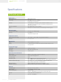
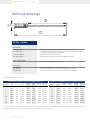
VPFlowScope dP
The VPFlowScope dP is designed for wet
air1. When properly applied, it can be
used in the discharge of the compressor.
The VPFlowScope dP is fully compatible
with the standard VPFlowScope, which
means that it is easy to install and
operate without additional training.
Typical applications
FlowScope dP
> Extreme resistance to pollution and
water drops
> Mass Flow, Pressure & Temperature
> Display/data logger module for easy
recording of data
>Wet air, untreated compressed air1
>High temperature up to 150 °C
(302 °F)
>High velocity applications
(undersized pipes)
1The VPFlowScope dP can be used up to a high
water content (saturated air). However, as it’s
based on the Pitot principle, some limitations
apply: The rangeability is smaller, no vertical lines,
no overflooding with water. See user manual for
details.
CAT-VP-UK-1501
© 2015 VPINSTRUMENTS
FLOWSCOPE DP | VP INSTRUMENTS
17
Specifications
VPFlow Scope dP
Flow sensor
Measuring principle
Flow range
Accuracy
Reference conditions
Gases
Differential pressure
20 ... 200 mn/sec | 65 ... 650 sfps
Bi-directional measurement
2% of reading over 1:10 range, under calibration conditions; Please
refer to the user manual for details. Recommended pipe diameter:
50 mm (2 inch) and up.
0 °C, 1013.25 mbar | 32 °F, 14.65 psi
Wet compressed air, Dry compressed air, Nitrogen and Inert gases.
Pressure sensor
Pressure sensor range
Accuracy
0 ... 16 bar | 0 ... 250 psi gauge
+/- 1.5% FSS
Temperature compensated
Temperature sensor
Temperature sensor range Accuracy
-40 ... +150 °C | -40 ... +302 °F. Icing should be avoided
+/- 1 °C | 1.8 °F
Data outputs
Digital
Analog
RS485, MODBUS RTU protocol
4 ... 20 mA output, selectable via software to indicate flow, pressure
or temperature
Display/data logger
Technology
Back light
Data logger
Liquid Crystal (LCD)
Blue, with auto power save
2 million points
Mechanical & environmental
Probe lengths
Process connection
Pressure rating
Protection grade Ambient temperature range
Wetted materials Corrosion resistance
400 mm | 15 inch (other lengths on request)
Compression fitting, 0,5 inch
PN16
IP52 | NEMA 12 when mated to display module
IP63 | NEMA 4 when mated to connector cap - do not mount upside down
-10 ... +50 °C | 14 ... 122 °F. Avoid direct sunlight or radiant heat
Higher ambient temperatures: consult factory
Anodized Aluminum, Stainless steel 316, Epoxy
Highly corrosive or acid environments should be avoided
Electrical
Connection type
Power supply
Power consumption UL/ CUL
CE
CAT-VP-UK-1501
© 2015 VPINSTRUMENTS
M12, 5 pin connector, female
12 ... 24 VDC +/- 10 % Class 2 (UL)
1 Watt +/- 10%
50 mA +/- 10% @24VDC, constant over the entire flow range
14 AZ, Industrial Control Equipment
EN 61326-1, EN 50082-1
FLOWSCOPE DP | VP INSTRUMENTS
18
Technical drawings
2
45
15
386
21
527
Or der codes
Flow meters
VPS.R200.P4DP.KIT VPFlowScope dP start kit, for air audits, complete with software
VPS.R200.P4DP.D11 VPFlowScope dP with 2 million point data logger display module, for auditors
and permanent installation (stand-alone)
VPS.R150.P400.D10
VPFlowScope with three row display
VPS.R200.P4DP.D2 VPFlowScope dP with connector cap. For Modbus networks
Other probe lengths
Only available in 400 mm probe length
Material :
Drawing nr. :
Debur and break sharp
edges
Accessories
FinishCable,
:
Unless
VPA.5000.005
otherwise specified
M12, 5 pole, for permanent connection
dimensions are in
VPA.5001.105
Interface
box JB5 with 5 m/ 16.4 ft cable + 12 VDC
power: supply
Name
millimeters
VPA.5001.900
Connector cap
with M12 socket for VPFlowScope sensor module
Tolerances
:
Approvals
Linear : NEN-ISO 2768-1-m ENG
QA
PROD
Other :NEN-ISO 2768-2-K
Further info acc. to :
Scale : 1:10
Drawn:
"Toleranties VPInstruments
NEN ISO
2768"
Date :
SHEET 1 OF 1
VPS.R200.P4DP flow range
table
VPS.R200.P4DP
All rights are reserved. Reproduction in whole or in part is prohibited without the written consent of the copy
S chedu le 4 0 Stan d a rd S e aml e ss Carb on S te e l P ip e
Schedule 10 Standard Seamless Carbon Steel Pipe
Size (inch)
DN
ID (inch)
ID
(mm)
Min flow
(scfm)
Max flow
(scfm)
(m3n/hr)
Min flow
Max flow
2
50
2.1
52.5
92
917
156
1,559
(m3n/hr)
ID (inch)
ID (mm)
Min flow
(scfm)
Max flow
(scfm)
(m3n/hr)
Min flow
Max flow
2.2
54.8
100
999
170
1,697
(m3n/hr)
3
80
3.1
77.9
202
2,021
343
3,434
3.3
82.8
228
2,282
388
3,877
4
100
4.0
102.3
348
3,481
591
5,913
4.3
108.2
390
3,897
662
6,621
6
150
6.1
154.1
790
7,899
1,342
13,420
6.4
161.5
868
8,678
1,474
14,743
8
200
8.0
202.7
1,368
13,678
2,324
23,238
8.3
211.6
1,490
14,897
2,531
25,309
10
250
10.2
259.1
2,234
22,341
3,796
37,957
10.4
264.7
2,332
23,316
3,961
39,612
12
300
11.9
303.2
3,060
30,604
5,199
51,994
12.4
314.7
3,296
32,965
5,601
56,006
16
400
15.0
381.0
4,832
48,316
8,209
82,087
15.6
396.8
5,242
52,420
8,906
89,058
20
500
18.8
477.8
7,599
75,994
12,911
129,110
19.6
496.9
8,219
82,191
13,964
139,638
The ranges apply only to compressed air and nitrogen. Contact us for other gases. The field accuracy of an insertion probe is typically +/- 5% due to
installation conditions. Insertion probes may not be used for official compressor testing.
CAT-VP-UK-1501
© 2015 VPINSTRUMENTS
FLOWSCOPE DP | VP INSTRUMENTS
‘The FlowScope is super easy
to install and allows me to show
customers just how important
measuring flow really is’
- Frank Moskowitz, Draw Professional Services
© 2015 VPINSTRUMENTS
19