1
SigTEL EVC System
SigTEL
Emergency Voice
Communication System
Installation and Configuration Guide
Approved Document No. DCP0001483 Rev 3
Page 1 of 32
SigTEL EVC System
Installation and Configuration Guide
CONTENTS
1.
2.
3.
4.
5.
6.
7.
8.
9.
10.
11.
12.
13.
14.
15.
16.
17.
18.
19.
20.
IMPORTANT ................................................................................................. 2
Emergency Voice Communication (EVC) Systems ................................... 3
SigTEL Components ................................................................................... 4
Cables .......................................................................................................... 6
Typical Systems .......................................................................................... 7
First Fix Installation ..................................................................................... 9
Mounting CCU-16 and SCU-16 Enclosures ............................................. 10
Mains Wiring .............................................................................................. 12
Fitting Outstations..................................................................................... 13
Second Fix Installation ............................................................................. 15
Testing Outstation Lines........................................................................... 18
Powering Up and Testing.......................................................................... 20
Optional Interfaces .................................................................................... 22
CCU-16 Error Codes .................................................................................. 23
ECU & CCU-16 Keypads............................................................................ 24
Automatic Configuration........................................................................... 26
Editing Outstation Names ......................................................................... 27
Component Specifications ....................................................................... 29
Identification of SigTEL EVC components .............................................. 31
Installation and Commissioning Certificate ............................................ 32
1. IMPORTANT
READ THIS SECTION BEFORE INSTALLING / MAINTAINING THIS PRODUCT
This equipment must only be installed and maintained by a suitably skilled and technically competent
person.
No responsibility can be accepted by the manufacturer or distributors of this product for any
misinterpretation of an instruction, or guidance note, or for the compliance of the system as a whole.
EVC system design is beyond the scope of this document. An understanding of system components and
their use is assumed.
About this guide
This guide explains how to install commission and maintain a SigTEL EVC disabled refuge and fire
telephone system. A separate Operator Instruction (ref. DCP0001928) includes detailed operational
information, some of which will need to be referred to by the installation engineer when setting up the
system.
No responsibility can be accepted by the manufacturers or distributors for any misinterpretation of these
instructions, or for the compliance of the system as a whole.
Note: This installation guide must not be accessible to the user.
System design
This document does not cover EVC system design. We recommend that you read BS 5839 Part 9
(available in libraries or from the BSI, www.bsonline.bsi-global.com) for this information.
Contact the building control or fire officer in case he has any special requirements.
SigTEL
Emergency Voice
Communication System
Approved Document No. DCP0001483 Rev 3
Page 2 of 32
SigTEL EVC System
Installation and Configuration Guide
Equipment guarantee
This equipment is not guaranteed unless the system is installed and commissioned in accordance with
national standards by an approved and competent person or organisation.
General precautions
Do not test wiring with an insulation tester (Megger) with any equipment connected as the 500 volt test will
destroy these devices totally.
You must observe local wiring regulations.
Do not run SELV and LV cables in the same enclosure without adequate insulation between them.
SigTEL EVC control equipment is designed to be installed indoors. Outstations are not IP rated so should
not be installed outdoors unless an IP 65, or better housing is used and cables are installed so as to
prevent the ingress of moisture.
Anti-static handling guidelines
Make sure that electro-static handling precautions are taken immediately before handling PCBs and other
static-sensitive components.
Before handling any static-sensitive items, operators should get rid of any electrostatic charge by touching
a sound safety earth.
Always handle PCBs by their sides and avoid touching any components.
PCBs should be stored in a clean, dry place that is free from vibration, dust and excessive heat.
Storing the PCBs in a suitable cardboard box will also guard them against mechanical damage.
2. Emergency Voice Communication (EVC) Systems
EVC systems are telephone, or intercom systems that are designed to operate reliably in a fire emergency.
This means that the equipment and wiring is monitored for faults that might occur before the emergency
and the cabling is designed to ensure that the equipment keeps working during an emergency.
There are two types of EVC systems; disabled refuge systems and fire telephone systems. They may be
separate, or they may be combined into one system.
Disabled refuge system
A disabled refuge system connects hands-free outstations to a central control room and is used during a
fire emergency to inform the management that someone needs immediate assistance to evacuate from
the building.
Fire telephone system
A fire telephone system is used by management (and marshals at a sports ground) and the fire service
before, during and after a fire to communicate with fire marshals and fire fighters.
Regulations affecting EVC systems
Disabled refuge systems are called for by DETR Approved document B (Fire safety) volume 2, section 4,
Design for vertical escape and BS 5588 Fire precautions in the design, construction and use of buildings,
Part 8, Code of practice for means of escape for disabled people.
Fire telephone systems for buildings are called for by BS 5588 Fire precautions in the design, construction
and use of buildings Part 5, Code of practice for firefighting stairs and lifts, Part10, Code of practice for
shopping complexes and Part 11, Code of practice for shops, offices, industrial, storage and other similar
buildings.
Fire telephone systems for sports venues are called for by the Guide to safety at sports grounds.
The installation of EVCs is covered by BS 5839-9 Fire detection and fire alarm systems for buildings –
Part 9: Code of practice for the design, installation, commissioning and maintenance of emergency voice
communication systems.
SigTEL
Emergency Voice
Communication System
Approved Document No. DCP0001483 Rev 3
Page 3 of 32
SigTEL EVC System
Installation and Configuration Guide
3. SigTEL Components
ECU-32/64/128 Desk control unit
This is the unit from which the operator communicates with
the outstations (see right). It is available in three versions:
ECU-32, which can control up to 32 lines; ECU-64, up to 64
lines; and ECU-128 for up to 128 lines.
CCU-16 master EVC control unit
The CCU-16 is a 16-line telephone exchange and main controller
(see right). It is supplied with a tone card that provides a ringing
tone, a busy tone, an alert tone and an evacuate tone.
SCU-16 slave EVC expansion unit
The SCU-16 is a 16-line telephone exchange (see right). Up to
seven SCU-16s can be connected to one CCU-16, giving a
maximum system size of 128 lines.
AFP385 grey flush bezel for CCU-16 and SCU-16
This flush bezel provides a neat finish when the CCU-16 or SCU-16
is semi-recessed (up to 60 mm).
LC2 2-way Line Card for Type A outstations
Each CCU-16 or SCU-16 allows up to eight LC2 Line Cards (see right). Each
LC2 enables two lines for Type A outstations (telephone handsets) to be
connected to a CCU-16 or SCU-16. One Type A outstation can be connected
per line.
LC3 2-way Line Card for Type B outstations
Each CCU-16 or SCU-16 allows up to eight LC3 Line Cards (see right). Each
LC3 enables two lines for Type B outstations (hands free outstations) to be
connected to a CCU-16 or SCU-16. One Type B outstation can be connected
per line.
Note: Both LC2 and LC3 outstations can be used on the same system.
SigTEL
Emergency Voice
Communication System
Approved Document No. DCP0001483 Rev 3
Page 4 of 32
SigTEL EVC System
Installation and Configuration Guide
SVMM Message Card
An optional SVMM message module (see right) may be fitted to the CCU-16 to
provide real speech for the same functions as the standard tone module.
THS1-EMK4 Type A Fire Telephone Outstation with key lock
One Type A outstation (see right) is connected to each line so that the Control
Room can call out to specific locations and also know which location is calling in.
The THS1-E, has a wall mounted key lockable red steel cabinet with all keys to
pass (identical).
The housing has openings to allow the ringing to be heard, a fire retardant window
with the legend “Fire Telephone” and may be surface mounted or semi-recessed.
THS1-ET/MK4 Type A Outstation with T-Bar handle
The THS1-ET has a wall-mounted non-locking T-Bar handle instead of a key lock.
T-BEZ flush-mounting bezel
This flush bezel provides a neat finish when the THS1E or ET is semi-recessed.
EVC302S surface mounting Type B hands-free duplex EVC outstation
One Type B outstation is connected to each line so that the Control Room can call
out to specific locations and also know which location is calling in.
The EVC302S has a stainless steel front plate with push-to-call or answer button,
ringing LED and buzzer and apertures for a microphone and loudspeaker.
EVC302F flush mounting Type B hands-free duplex EVC outstation
Similar to the S version but with a flat front plate suitable for flush installation (see
right).
An IP66 rated housing (BF359/1), is available to allow the EVC302F to be used
outdoors (see below).
BF359/1 IP66 Type B Outstation Box
The EVC302W is used to protect an EVC302F outstation when used as an
external disabled refuge. It is supplied with a non-locking handle as
disabled refuge points should not normally be locked.
Note: The EVC302S will not fit inside this box.
EVC302WL
Locking handle for use with EVC302W.
Note: This part is only used in special circumstances.
SigTEL
Emergency Voice
Communication System
Approved Document No. DCP0001483 Rev 3
Page 5 of 32
SigTEL EVC System
Installation and Configuration Guide
ECU-WMB wall mount bracket
The ECU is intended to be free-standing. However, a sloping wall
mounting shelf, ECU-WMB is available.
The ECU-WMB is finished in semi-gloss black powder coating
and is angled at 38 degrees.
38º
4. Cables
Cables used between EVC components should have enhanced fire resistance [see 26.2e of
BS 5839-1:2002], except for underground sections of cabling at sports and similar venues.
See BS 5839-9:2003 section 14 for details.
Outstation lines
2-cores are required for each line and they should use 1 mm2 or 1.5 mm2 enhanced cable. Larger cables
will stress the connectors.
The maximum cable resistance is 40 ohms, which is 1000 metres of 1 mm2. If this exceeded, outstations
may not work properly.
CCU-16 to SCU-16, SCU-16 to SCU-16
The maximum length of cable between any two exchanges is 200 metres.
HOWEVER, the maximum length of cable between the CCU and the last SCU is 800 metres.
Therefore if three units are each 200 metres apart, the remaining units must be connected on no more
than 200 metres.
ECU-16 to CCU
These should be connected using fire-rated cable up to 200 metres.
The ECU-16 should be installed in a control room and the supplied 5 metre Cat-5 lead used to connect to
an adjacent Cat-5 socket and with mechanical protection in accordance with BS 5839-1:2002.
SigTEL
Emergency Voice
Communication System
Approved Document No. DCP0001483 Rev 3
Page 6 of 32
SigTEL EVC System
Installation and Configuration Guide
5. Typical Systems
System up to 4 lines (see right)
Equipment required
One ECU-32 master exchange
Optional Cat 5 wall socket and back box
One CCU-16 slave exchange
Two 12 volt 7 Ah batteries
One 3 A fused spur and back box
One LC2 per two lines of Type A outstations
One LC3 per two lines of Type B outstations
One THS1-E Type A or EVC302 Type B outstation per line
One FiTT Telephone Line Tester
Interconnections
For each phone line, up to 1 km of 2-core 1.5 mm2
enhanced fire-rated cable.
Between the CCU-16 and the ECU-32; two 4-core
1.5 mm2 fire-rated cables up to 200 metres.
Note: If an odd number of outstations are required, there is
no need to connect anything to the unused terminals.
When the system is configured an outstation will not be
found and so a fault will not be reported.
SigTEL
Emergency Voice
Communication System
Approved Document No. DCP0001483 Rev 3
Page 7 of 32
SigTEL EVC System
Installation and Configuration Guide
System up to 128 lines (see below right)
Equipment required
One ECU-32, 64 or 128 dial unit
One CCU-16 Exchange
Two 12 volt 7 Ah batteries per CCU & SCU
One LC2 per two lines for Type A outstations
One THS1-E Type A or EVC302 Type B outstations
per line
Cat 5 wall socket and back box
Up to seven SCU-16s
One 3 A fused spur and back box per CCU & SCU
One LC3 per two lines for Type B outstations
One FiTT Telephone Line Tester
Interconnections
For each phone line,
2-core 1.0 mm2 or
1.5 mm2 enhanced
fire-rated cable, up to
1000 m each.
Between the CCU-16
and the ECU, two
4-core 1.5 mm2 firerated cables.
SigTEL
Emergency Voice
Communication System
Approved Document No. DCP0001483 Rev 3
Page 8 of 32
SigTEL EVC System
Installation and Configuration Guide
6. First Fix Installation
Equipment Location
Control equipment
Unless protected from the elements, all equipment must be sited indoors and MUST NOT be subjected to
conditions likely to affect its performance, such as damp, salt air, water, extreme temperatures, physical
abuse, etc.
The ECU, CCU and SCUs should be located in areas of low fire risk, usually in the control room.
The CCU / SCUs are wall-mounted and the ECU is normally free-standing on the control console.
Wall-mounted equipment should be sited at an easily accessible height, with the LCD at eye level, typically
1.4 metres above final floor level.
The interconnecting cable from the ECU to the CCU-16 is fully monitored and a fault will sound at the CCU
if it is removed or damaged.
Outstations
Type A outstations should be located at entrances and fire fighting lobbies and should normally be
mounted 1.3 m to 1.4 m from the ground.
Type B outstations should be located in disabled refuges at each storey exit and should normally be
mounted 0.9 m to 1.2 m from the ground.
Outdoor installations
Outstations may be mounted in an IP 65, or better box, with an easily opened door. Steps should be taken
to ensure that moisture does not enter and damage the electronics.
Sports stadiums
In sports stadiums, Type A outstations should be located no more than 30 metres from stewards‟ positions
or other normally manned areas as listed in the Guide to Safety in Sports Grounds. If they are exposed to
the elements they should be mounted in an IP 65 or better box with an easily opened door. Steps should
be taken to ensure that moisture does not enter and damage the electronics.
Strobe driver module
If the ringer is not loud enough a flashing red strobe light and / or sounder may be fitted to any Type A and
Type B outstation.
A strobe driver module, SDM, which can switch up to one amp, should be connected across the line to
sense when the outstation rings.
An external 12 VDC power supply must be connected to the strobe module to provide power for the
module and/or sounder. This may be provided local to the outstation or centrally, in which case two extra
cores will be required and voltage drop should be taken into account.
SigTEL
Emergency Voice
Communication System
Approved Document No. DCP0001483 Rev 3
Page 9 of 32
SigTEL EVC System
Installation and Configuration Guide
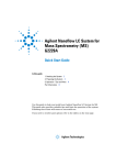
7. Mounting CCU-16 and SCU-16 Enclosures
The Central Control Unit (CCU-16) and Slave Control Unit (SCU-16) are supplied in a metal back-box with
a hinged plastic lid and several printed circuit boards (PCBs), as shown below.
Metal Back Box
Plastic Lid
Message or
Tone Module
Master PCB
Power Supply PCB
Exchange PCB
CCU-16 Central Control Unit
Plastic Lid
Metal Back Box
Slave Display PCB
Power Supply PCB
Exchange PCB
SCU-16 Slave Control Unit
The CCU-16 and SCU-16 can be surface or semi-flush mounted to allow clearance for front panel opening
(max depth 60 mm including dimples). To expose the base mounting holes and to protect the hinged lid
and PCBs from damage during installation, they must first be removed. Before any of the following is
carried out ensure that the mains power supply is isolated and the batteries are removed.
Remove the lid
Take the panel out of its box and undo the two screws on the right hand side of the lid using a 3 mm Allen
key.
Hinge the lid 180° to the left. Unplug the lid/base connecting cable from the Exchange PCB (20-way boxed
header). Carefully remove the four M4 retaining nuts that secure the hinges.
SigTEL
Emergency Voice
Communication System
Approved Document No. DCP0001483 Rev 3
Page 10 of 32
SigTEL EVC System
Installation and Configuration Guide
Remove the base PCBs
Carefully remove all line cards from the Exchange PCB using correct anti-static handling procedures and
store them in anti-static bags.
Disconnect the cable from the PSU to the Exchange PCB.
Disconnect the earth strap spade connector from the main chassis earth point.
Carefully remove the PCB retaining screw located at the bottom left hand side of the relevant PCB.
Push the PCB upwards and then pull forwards over the mounting pillars taking care not to damage any of
the components.
The panel lid and base PCBs should now be removed from site to prevent accidental damage.
Note: All PCBs are static sensitive and anti-static handling precautions MUST be observed when handling
them.
Remove knockouts & cut gland holes
Decide how the wiring will be brought into the
panel and remove the knock-outs required for
cable entry. Use suitable cable glands and
securely blank off unused knock-outs.
If more than six lines are to be brought into a
CCU-16 or SCU-16, a separate 20 mm hole must
be cut for each extra line. See diagram for
suggested locations for the holes.
Note: This must be done before re-installation of
circuit boards to avoid swarf getting into the
electronics.
40 mm
50 mm
Existing knock-outs
Extra 20 mm holes
20 mm
Interconnections
Cable glands are provided in the bottom left hand side of the base to allow the units to be connected with
fire-rated cables.
Fix the base to the wall
Using the four mounting holes, fix the base securely to the wall using a suitable screw fixing. The mounting
holes are designed for No. 8 round-head or countersunk wood-screws. Any dust or swarf must be kept out
of the enclosure and great care must be taken not to damage the wiring or components.
Re-install the PCBs
Re-install the base PCBs, with the exception of the line-cards, and refit the lid. Ensure the fixing screws
and all interconnection cables are refitted correctly.
Install the optional SVMM message module
If an SVMM message module is required, identify the
existing tone module on the plastic lid of the CCU-16,
undo the two screws on the right of the tone module and
gently pull it off the Master PCB.
Carefully locate the plug on the underside of the SVMM
in the socket of the Master PCB and push it on. If the
fixing screw holes are not correctly aligned, the plug is
not fitted correctly. Fix the SVMM fixing screws to the
mounting pillars.
SigTEL
Emergency Voice
Communication System
Plastic Lid
Tone Module
Message Module
Master PCB
Approved Document No. DCP0001483 Rev 3
Page 11 of 32
SigTEL EVC System
Installation and Configuration Guide
8. Mains Wiring
Connect mains to the CCU and SCUs
See BS 5839-9 2003 section 13.
Each exchange requires fixed wiring using 3-core cable (no less than 0.75 mm2 and no more than
2.5 mm2) fed from an isolating un-switched fused spur, fused at 3 amps and must not be connected using
a plug and socket. The 230 VAC cable MUST enter the enclosure via one of the inlets at the top right hand
corner of the enclosure.
Ensure that mains cables are kept as far away as possible from all other cables.
The mains supply should be exclusive to the EVC system. Circuit breakers supplying power to the system
should be marked “EMERGENCY VOICE COMMUNICATION SYSTEM - DO NOT SWITCH OFF”.
A separate fused spur should be used for the CCU-16 and each SCU-16 and should be marked
“EMERGENCY VOICE COMMUNICATION SYSTEM - DO NOT SWITCH OFF”.
See BS 5839-9 section 13.2 for more details
Terminate the mains input lead using the three-way plug
LEN
supplied with the power supply PCB and ensure that correct
Mains fuse
230 VAC
P2
1 A HRC
polarity is observed.
The incoming mains earth connection must be connected
directly to the three-way plug (P2) and NOT to the main
chassis earth-point.
The Power Supply Unit (PSU) earth strap must be
connected to the main chassis earth point before operation.
SigTEL
Emergency Voice
Communication System
Approved Document No. DCP0001483 Rev 3
Factory set at
27.6 VDC.
Do not adjust.
Batt fuse
1 A (F)
Battery
connector
Page 12 of 32
SigTEL EVC System
Installation and Configuration Guide
9. Fitting Outstations
Cables
Use 2-core enhanced fire-resistant cable for each outstation line, conductor size 1 mm2 to 1.5 mm2.
Maximum recommended cable distance is 1 km, beyond which audio quality will degrade.
Maximum cable resistance before the outstations will not ring reliably and the fault monitoring system will
not work is 40 ohms.
General
Type A outstations should normally be mounted 1.3 m to 1.4 m above final floor level and Type B should
normally be mounted 0.9 m to 1.2 m above final floor level in an easily accessible, well illuminated and
conspicuous position free from obstruction.
As far as practicable, outstations should be located where background noise is normally low (preferably
not more than 40 dBA). Where there is a higher level of background noise the installation of an acoustic
hood around the outstation might help to reduce the effect of background noise to an acceptable level.
Fitting the THS1-E or THS 1-ET Type A Outstation (Telephone)
Open the case and unscrew the eight cross-head screws to remove
the internal cover (see right). This reveals the terminals and earth
stud. Fix to the wall, remove the knock out above the terminals and fit
a suitable cable gland.
Connect the wires, as shown right
To SCU/CCU
Red +
Black E ig ht c o ve r s c re ws
Fitting Type B outstation (Hands free)
EVC302S - Surface mounting.
EVC302F - Flush mounting.
Red +
GreenBoth units are supplied complete with a back box
that should be fitted to the wall using suitable
fasteners. The back box has 20 mm knock-outs
at the top and bottom. Gland the cable correctly and connect a sleeved earth wire to the earth stud.
Connect the line to the LINE IN + and – terminals.
When installation is complete, secure the lid using the four machine screws. These have a secure pin-hex
design that requires a special Allen key (supplied).
SigTEL
Emergency Voice
Communication System
Approved Document No. DCP0001483 Rev 3
Page 13 of 32
SigTEL EVC System
Installation and Configuration Guide
Connections
SW OUT
LINE IN EARTH
AUDIO OUT
Connecting to an induction loop system
If an audio induction loop facility is required, the AUDIO OUT terminals should be connected to a line-level
input of a suitable induction loop amplifier and an induction loop should be located adjacent to the
outstation so that it covers the immediate area of the outstation adequately.
Connecting to a CCTV camera
When the outstation is active the opto-isolated SW OUT terminals close and can be used to trigger a
CCTV camera or recorder. The maximum current they can pass is 3 mA at 24 VDC.
If this current is exceeded, the output will be damaged.
If required, an RLPV relay and a 24 VDC power supply can be used to give two sets of volt-free changeover contacts.
SigTEL
Emergency Voice
Communication System
Approved Document No. DCP0001483 Rev 3
Page 14 of 32
SigTEL EVC System
Installation and Configuration Guide
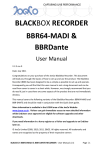
10. Second Fix Installation
CCU-16 Master Exchange to ECU-32, 64 or 128 Master Controller
Cut off the release tabs and plug the supplied Cat 5 lead into the back of the ECU. Mount a twin single
back box in a suitable location near to the control location* and connect two 4-core fire-rated cables to the
supplied CAT 5 faceplate, as shown below.
Use one 4-core for TX-, TX+, RX- and RX+ and one 4-core for +24V, GND, Audio + and Audio –.
Note: Do not mix audio and data in one fire-rated cable as there is no internal screening. The audio quality
will be severely degraded and the system may not operate reliably.
IMPORTANT
Maximum distance
from CCU-16 to
ECU is 200 metres.
Slave Out
Slave In
ECU 128 Only
CCU-16
Cat 5
Colours
Blue
Wt/Blue
Green
Wt/Green
Brown
Wt/Brown
Orange
Wt/Orange
8-way terminal blocks
Cat 5
Colours
Wt/Orange
Pass
cables
through
glands
Orange
Wt/Green
Blue
Wt/Blue
Green
Wt/Brown
Brown
Twin single back box with Cat 5 socket
Use a blank plate to cover the unused part
ECU-32, 64 or 128 Master Controller
SigTEL
Emergency Voice
Communication System
Approved Document No. DCP0001483 Rev 3
Page 15 of 32
SigTEL EVC System
Installation and Configuration Guide
CCU-16 Master Exchange to SCU-16 Slave Exchange
If the system has more than sixteen lines, one SCU-16 unit is required for every additional 16 lines to be
connected, up to a maximum of seven SCUs and 128 lines.
Slave Out
Slave In
ECU 128 Only
Blue
Wt/Blue
Green
Wt/Green
Brown
Wt/Brown
Orange
Wt/Orange
IMPORTANT
Maximum distance
from CCU-16 to SCU16 is 200 metres.
Maximum length of
cables to final SCU16 is 800 metres.
Cat 5
Colours
CCU-16
Pass
cables
through
glands
Slave Out
Slave In
SCU-16
Cat 5
Colours
Blue
Wt/Blue
Green
Wt/Green
Brown
Wt/Brown
Orange
Wt/Orange
ECU 128 Only
Pass
cables
through
glands
SigTEL
Emergency Voice
Communication System
Approved Document No. DCP0001483 Rev 3
Page 16 of 32
SigTEL EVC System
Installation and Configuration Guide
SCU-16 Slave Exchange to SCU-16 Slave Exchange
Slave Out
Slave In
ECU 128 Only
Blue
Wt/Blue
Green
Wt/Green
Brown
Wt/Brown
Orange
Wt/Orange
IMPORTANT
Maximum distance
from CCU-16 to SCU16 is 200 metres.
Maximum length of
cables to final SCU-16
is 800 metres.
Cat 5
Colours
SCU-16
Pass
cables
through
glands
Slave Out
Slave In
SCU-16
Blue
Wt/Blue
Green
Wt/Green
Brown
Wt/Brown
Orange
Wt/Orange
ECU 128 Only
Pass
cables
through
glands
SigTEL
Emergency Voice
Communication System
Approved Document No. DCP0001483 Rev 3
Page 17 of 32
SigTEL EVC System
Installation and Configuration Guide
Address the CCU and SCU-16
The CCU-16 and each SCU-16 must be given a unique address.
On
On
SCU 4, Exchange 5
CCU, Exchange 1
On
On
SCU 5, Exchange 6
SCU 1, Exchange 2
ECU 128
ONLY
On
On
SCU 6, Exchange 7
SCU 2, Exchange 3
Reset
Program
On
Address
On
SCU 7, Exchange 8
SCU 3, Exchange 4
Addressing is done by setting the DIP switches, marked Address on the exchange PCB, as shown above.
11. Testing Outstation Lines
Insulation Resistance Testing
Insulation resistance testing should be carried out with no electronic devices attached. Any devices
connected to the lines will be destroyed and will not be covered by factory warranty.
The FiTT Line Tester
Each outstation line should be tested prior to termination and connection to
the exchange circuit board. We recommend that a SigTEL FiTT line tester
(shown right) is used to save time proving the cables and outstations are
working correctly.
It also avoids the need for mains power for testing.
If a FiTT line tester is not available, use a multi-meter to check wiring for
continuity and correct polarity
Connecting Outstation Lines
Do not connect the lines until they have been tested and are fault-free.
Connecting Lines to the CCU / SCU
Connect the wiring before fitting the line cards.
Each line should be brought into the enclosure through a separate
cable gland. If more than six lines are connected, a separate
20 mm hole must be cut for each gland prior to re-installation of the
circuit boards.
Connect the red and black cores of the field wiring, as shown right.
Insulate the cable earth screens and connect them to the earth stud.
Fit the two-way connectors to pins L1 to L16. If both lines on the line
card are used, fit the connectors together to form a 4-way plug before
they are attached.
Black
-
+Red
Connect screen
to earth point
Fault Monitoring
Once connected, the line fault monitoring system monitors for open
and short circuits (absence of a device constitutes open circuit).
SigTEL
Emergency Voice
Communication System
Approved Document No. DCP0001483 Rev 3
Page 18 of 32
SigTEL EVC System
Installation and Configuration Guide
Fit the Line cards
A line card (LC2 or LC3) must be fitted for every two lines used.
For example: If two lines are connected, terminals L1 and L2, fit a line card, as shown below.
Note: The LC2 line card can only be connected to Type A outstations. The LC3 line card can only be
connected to Type B outstations.
L1
L2
L3
L4
L5
L6
L7
L8
L9
L1
0
L11 L13 L15
L12 L14 L16
o
n
Ad
If one line is connected, e.g. to terminals L9 and L10, fit a line card as shown below.
L1
L2
L3
L4
L5
L6
L7
L8
L9
L1
0
L11 L13 L15
L12 L14 L16
o
n
Ad
Fit the LC2 or LC3 Line cards
Grasp the line card at each end with the surface-mount components facing to the right. Identify the two
connectors and locate them over the relevant connectors on the exchange circuit board, taking care that
all the pins are mated correctly. Push the line card firmly on to the pins.
Notes:
1. Where a line card is fitted but a line is unused, e.g. for future expansion, no connections need be
made to the terminals.
2. Where no line card is fitted, no connections need be made to the terminals.
SigTEL
Emergency Voice
Communication System
Approved Document No. DCP0001483 Rev 3
Page 19 of 32
SigTEL EVC System
Installation and Configuration Guide
12. Powering Up and Testing
Testing using batteries
Note: If mains supply is not present for commissioning, use fully charged batteries.
The system can be set up using batteries only provided their terminal voltage is at least 22 VDC.
Two 12 volt 7 Ah VRLA batteries should be used for the CCU-16 and each SCU-16. These should be
connected in SERIES using the link provided with each unit.
Do not leave batteries attached whilst the mains is not connected or is subject to disruption as the
batteries will become fully discharged and will have to be replaced.
Testing using mains
Fit the 3 amp fuses into the un-switched fused spurs.
Turning the power on
As soon as the CCU-16 receives power, the handsets will ring for a moment and the CCU-16 may sound a
continuous fault buzzer. This is normal and will clear once the system has been configured.
As soon as power is applied, the system looks at each line card that has been fitted and configured and
tests the lines for a correctly connected outstation. If any outstations have not been fitted, or are incorrectly
connected, they will show up as faults straight away.
Check the LCD on the CCU-16
The LCD will display a message similar to the following, where „N‟ can be any number.
N faults logged; N current ()
Day
1 : Extension N Hand Set Open Cct.
The second line of the display will scroll and show all the faults in turn. If the system is being tested on
mains only, one message will be „Exchange 1 Battery Failure‟.
If the system is being tested on batteries, one message will be „Exchange 1 Power Fail‟.
Temporarily silencing the fault buzzer
If you wish to mute the fault buzzer, go the CCU-16 and enter the default code 144111.
This PIN can be changed if required. See page 24 for details.
As soon as you press the first „1‟ the display changes and the top line displays the following:
Enter PIN : #
1 : Extension N Hand Set Open Cct.
As you enter the other numbers, the * symbols change to # symbols.
As soon as the PIN is correctly entered, the fault buzzer stops and the display reverts.
If you enter the wrong PIN the display shows the following:
Wrong PIN
1 : Extension N Hand Set Open Cct.
SigTEL
Emergency Voice
Communication System
Approved Document No. DCP0001483 Rev 3
Page 20 of 32
SigTEL EVC System
Installation and Configuration Guide
Check the CCU-16 Indicators
The exact indication will depend on the nature of the faults found on switch-on.
Typical Indications
STATUS column
OK
Off
FAULT
Yellow
PROCESSOR FAIL Off
If processor fail is lit, there is a serious problem with the
microprocessor on that unit.
NETWORK column
Tx
Dim flickering green
Rx
Dim flickering green
SYNC
Off
If the yellow SYNC LED is lit, there is a problem with the data
communications between the CCU-16 and the SCU-16(s).
SUPPLY column
AC
DC
FAULT
S T AT U S
S T AT U S
N E T W O RK
N ETW O R K
SU PPLY
SU PPLY
OK
OK
Tx
Tx
AC
AC
Rx
Rx
DC
DC
SYNC
SYNC
FAU L T
F AUL T
F AU LT
F AU L T
PROCESSOR
P RO C E S S O R
FAIL
F AIL
Green if mains connected, off if not
Green if batteries connected, off if not
Yellow if either mains or batteries are not connected
Check the ECU is working
The green power LED should be lit.
The display should be lit and display the software code version „SigTEL Dial Vx.x.x‟.
Check all outstations are working.
Go to each outstation in turn and try to make a call. If you hear ringing tone, it is OK. If not, check for
correct polarity, or cable faults.
When you are satisfied that all the outstations are connected, you can begin the system configuration.
Fit the Batteries
Once the system is OK, fit the batteries (2 x 12 V 7 Ah VRLA) for the CCU-16 and each SCU-16. Use the
links provided to connect the batteries in series.
SigTEL
Emergency Voice
Communication System
Approved Document No. DCP0001483 Rev 3
Page 21 of 32
SigTEL EVC System
Installation and Configuration Guide
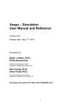
13. Optional Interfaces
Fault output to fire alarm system
If the CCU is installed away from the control room, the fault
buzzer may not be heard so the common fault output can
be connected to a fire alarm system.
This output is an open collector with a maximum current
capability of 50 mA.
Message
or tone
module
+ Common Fault
- (NC)
Master PCB
Connection to a relay
The fault output can switch a 24 volt relay with a coil
resistance of not less than 470 ohms.
Connect as shown below and make sure a 1N4001 diode
is connected across the coil to protect the output from
back-e.m.f. The relay will be normally energised and will
release when a fault occurs.
Common
Fault
+
-
1N4001
Relay, >470R + 24 Vd.c.
Connection to a fire alarm
Common 20 K end
The fault output can be connected to a fire alarm via an
Fault
of line
+
I/P
input unit connected to a detection loop.
+
I/P The following details are for the Apollo XP95 Input/Output
Unit.
The 20 kohm resistor supplied with the unit should be connected at the CCU-16. When a fault occurs the
fault output goes open circuit.
The unit sees this as a fault and passes this information to the fire alarm panel, which should be
configured to display it as a fire telephone fault.
Triggering from a fire detection system
This feature is normally used in conjunction with a SVMM message storage unit.
When triggered, all phones ring. When they are picked up, an „alert‟ or „evacuate‟ message (or tone if the
tone module is fitted) will be heard.
If both messages are triggered, the evacuate message will be heard. The messages continue to play until
cancelled by a reset signal.
Audio from a PA or VA system
A line level audio output from a PA / VA system can be connected, along with a trigger connection. When
the trigger connection is closed, all phones ring and the audio from the PA may be heard at all handsets.
This takes priority over the recorded messages (if fitted).
Important
To make sure that the fire telephone will be operational when needed it should only be able to be triggered
when the control room is unmanned.
If any input is asserted, the fire telephone can still be used from the control room which will have priority
over all other messages or tones.
However, when a handset is picked up, a call will not be made to the control room, instead, the emergency
message will be heard.
SigTEL
Emergency Voice
Communication System
Approved Document No. DCP0001483 Rev 3
Page 22 of 32
SigTEL EVC System
Installation and Configuration Guide
PA
Alert Cancel Evac
Connections
S
0
S
0
S
0
0
S
+
-
Connect to
fire detection
system
Connect to
public address
system
Ribbon
Cable
Master PCB
PA
PA+, PAUnbalanced line audio input
S, 0 Close a switch between S and 0 and
audio from the PA system will be routed to all
telephones.
Evac
S,0
Close a switch between S and 0 to play
the evacuation tone or message to all
telephones. Continues until cancelled.
Alert
S,0
Close a switch between S and 0 to play
the alert tone or message to all telephones.
Continues until cancelled.
Cancel
To cancel the Evacuate and Alert tones or
messages, remove the triggers and then close a
switch across S and 0.
Messages will stop immediately and not play to
the end.
14. CCU-16 Error Codes
The CCU-16 display has two lines. If there are no faults, the first line shows the current software version. If
there are faults, the message depends on the current mode and whether anyone is logged in.
Latching fault display mode
This is the normal mode. If no-one is logged in, the top line displays information in the format:
„x faults logged; y current (*)‟ where x and y are any number
Or, if someone is logged in, the format will be:
„x faults logged; y current (*). √ = Accept‟
The second line gives details of the fault in text.
Non-latching fault display mode
This mode is used during commissioning to prevent temporary faults appearing to be permanent. The
system should not be left in this mode after hand-over.
The top line displays information in the format:
„x faults logged‟.
Fault Alarm Mute Mode
This mode is used to prevent the fault buzzer sounding during commissioning. The system should not be
left in this mode after hand-over.
Default Fault messages
For the following messages, check the wiring between the CCU & SCUs:
Master Unit APB line open circuit
Master Unit APB line short circuit
SigTEL
Emergency Voice
Communication System
Approved Document No. DCP0001483 Rev 3
Page 23 of 32
SigTEL EVC System
Installation and Configuration Guide
Master Unit speech line open circuit
Master Unit speech line short circuit
Exchange X APB line open circuit
Exchange X APB line short circuit
Exchange X speech line open circuit
Exchange X speech line short circuit
The following show a fundamental problem with the unit. Check all connectors are firmly in place.
Master Unit Program Checksum Fail (CCU-16)
Master Unit EEPROM Checksum Fail (CCU-16)
Exchange X Program Checksum Fail (CCU-16 or SCU-16)
Exchange X EEPROM Checksum Fail (CCU-16 or SCU-16)
Exchange X Data Checksum Fail (CCU-16 or SCU-16)
Dial Unit X Program Checksum Fail (ECU)
Dial Unit X EEPROM Checksum Fail (ECU)
Dial Unit X Data Checksum Fail (ECU)
Exchange X Comms Time Out (SCU-16)
Dial Unit X Comms Time Out (ECU)
Exchange X Sync Error (s) (CCU-16 or SCU-16)
Dial Unit X Sync Error (s) (ECU)
Check the relevant telephone line.
Extension XX Hand Set Open Circuit
Extension XX Hand Set Short Circuit
Problem with the message store or tone module
Master Unit MP2 Fault
Problem with the mains or battery
Exchange X Power Fail
Exchange X Battery Fail
15. ECU & CCU-16 Keypads
Six keypad functions can be called up by pressing „F‟ and a key 1 to 6. If the number key is not pressed
within 2.5 seconds the F key must be pressed again.
F1, Auto Configure
This function looks at the linecards fitted to the system and searches for outstation extensions connected
to them.
Enter the default PIN 2222 and the system will automatically configure.
Faults are not recorded during configuration.
F2 Directory Edit
Enters directory edit mode. PIN protected, default 2222.
F3 Latching/non-latching faults
Switches the fault-logging mode between latching and non-latching mode. PIN protected, default 2222.
F4 Change PINs
Press F followed by 4.
This allows PINs to be changed. PIN protected, default 2222.
All three PINs can be changed with this function.
SigTEL
Emergency Voice
Communication System
Approved Document No. DCP0001483 Rev 3
Page 24 of 32
SigTEL EVC System
Installation and Configuration Guide
After pressing the function key and 4, enter the edit PIN number, default 2222.
You are then given a sub menu with three options. The option you require may be selected by using the
and ↑ and ↓ keys and the * key, or by keying in the option number.
After making the selection you will be asked to enter one of the following:
The Edit PIN
This is the PIN number for the ECU dial unit and is used in all editing.
It is 4 digits long (default 2222) and may contain any of the digits 0 - 9. It may not contain *, # or any of the
special keys.
After entering the new PIN number, you will be asked to confirm selection by typing the number again.
If this PIN is lost, the ECU must be returned to the manufacturer to be reset.
This is chargeable.
The Fault Acknowledge PIN
This number is used on the CCU-16 Master Control to acknowledge faults.
It is a 6 digit number (default 222222) using only the digits 1 - 4. No other keys are allowed.
After entering the new PIN, you will be asked to confirm selection by entering it again.
If this number is lost, a new PIN can be entered without knowing the original.
The Mute PIN
This PIN disables or re-enables the fault buzzer on the CCU-16 unit.
It is a 6 digit number (default 144111) using only the digits 1 - 4. No other keys are allowed.
After entering the new PIN, you will be asked to confirm selection by typing the number again.
If this number is forgotten, a new PIN can be entered without knowing the original.
If you make this PIN the same as the Fault Acknowledge PIN, the MUTE function is disabled.
F6, Night Service Configuration
This is PIN protected (default 2222).
This is used to choose the night service extension.
The extension is selected from the directory using the ↑ ↓ and * keys.
F5, Night Service
In Day Mode, press F & 5 to select Night Service, press F & 5 again to switch back to Day Mode.
In Night Service the ECU keypad is disabled. Instead the selected outstation operates as a “receive any,
broadcast to all” outstation.
If this extension is lifted, all other outstations except the ECU Dial Unit will ring and can hear the night
service outstation but cannot speak to it.
If any other handset except the ECU 128 Dial Unit is lifted, it calls the night service handset. These two
handsets can hold a two-way conversation. The handset is still monitored by the CCU-16 exchange, but
otherwise the ECU is dormant.
Note: Type B outstations (hands free outstation) must not be used as a night service master.
SigTEL
Emergency Voice
Communication System
Approved Document No. DCP0001483 Rev 3
Page 25 of 32
SigTEL EVC System
Installation and Configuration Guide
16. Automatic Configuration
Once you are satisfied that everything is functioning correctly, the system should be configured.
At the ECU Dial Unit and press F1.
The display reads:
Enter
EnterPIN
PIN: :
Auto Configure
Auto Configure
Enter the PIN, default 2222.
The ECU display reads as follows for five seconds whilst the system searches for all the phones.
At the same time, the CCU-16 display reads „Auto Config‟ and the Tx and Rx lights flicker.
Auto Configure
Auto Configure
As set-up finishes, the PROCESSOR FAIL light comes on briefly.
Check Configuration
Each line card position has a unique extension number. The CCU contains lines 1 to 16; the first SCU
contains lines 17 to 32, and so on.
When the system auto-configures, it looks at each line in turn and remembers the extensions it finds.
To check configuration, press D on the ECU. The display lists all the extensions found. Use ↑and ↓ to
scroll through the list, which should be the same as the extensions numbers you expect. Any missing
extensions should be investigated.
If the fault cannot be located, swap outstation lines and see if the fault stays or moves with the line. If it
stays, it is an equipment fault; if it moves, it is a wiring fault or faulty outstation.
If it is an equipment fault, power down and swap the line card. If the fault moves with the line card, it is a
line card fault. If it stays with the extension cable, it is a wiring or outstation fault so use the FiTT to test or
try swapping the outstation.
SigTEL
Emergency Voice
Communication System
Approved Document No. DCP0001483 Rev 3
Page 26 of 32
SigTEL EVC System
Installation and Configuration Guide
17. Editing Outstation Names
Outstation names can be changed from the ECU Master Controller. The default name of an outstation is
„Extension‟ followed by the outstation number (two digits for outstations 1 - 99 and 3 digits for outstations
100 - 128).
You should give meaningful names to outstations to enable the operator to see which is calling.
The directory can be used to select which outstation to call by name, without knowing the number.
In order to edit outstations press F2 at the ECU Master Controller, followed by the Edit PIN number,
default 2222
You will see the following screen
To name an outstation, use ↑ and ↓ to highlight it thus > 01 Extension 01 <.
01: Extension 01
> 01 Extension 01 <
02 Extension 02
03 Extension 03
The first letter of the word Extension is flashing and underlined. This can be altered by using the keypad in
a similar way to that used on mobile telephones.
The first press on a button selects one letter; further presses select the next letter as shown below.
Once you have selected the right letter, press * to accept. The flashing cursor will move to the right. If you
want to go back, press #.
Note: When entering this mode, the last person you called or who called you is automatically displayed
first, ready for editing. This is handy during installation. Get someone to walk the area and pick up each
phone or press the button on the Type B (hands free) outstation in turn, saying where they are. Then go
into edit mode and change the description. This also confirms the audio quality of the extension is
satisfactory.
Special characters on the 0 key (< > and > <) allow characters to be inserted and deleted. These keys
may be used repeatedly, and so they stay active until another key such as the # key is pressed.
If you accidentally start to change a letter you can cancel the change at any point before you accept (with
the * key), by pressing #. This includes the insert and cancel keys described above.
This only works before * is pressed. It does not undo changes.
Storing the changes
Pressing the ↑ or ↓ key confirms the changes and you will see the new name at the bottom of the display.
Further presses of the ↑ or ↓ key scroll the directory as normal. Until the ↑ or ↓ key is pressed, you can
abort the change by pressing the Function key to leave edit mode.
You will then have to log in again before you can carry out any other changes.
Finishing
To return the keypad to normal operation and save all the changes permanently, press the Function key.
This also causes checksums to be recalculated on the unit.
Important: if you power down before pressing the Function key, checksums will not be recalculated and a
permanent fault will occur.
SigTEL
Emergency Voice
Communication System
Approved Document No. DCP0001483 Rev 3
Page 27 of 32
SigTEL EVC System
Installation and Configuration Guide
Characters associated with each key
1st
Press
2nd
Press
3rd
Press
4th
Press
5th
Press
6th
Press
7th
Press
8th
Press
9th
Press
1
A
B
C
a
b
c
1
(
)
2
D
E
F
d
e
f
2
[
]
3
G
H
I
g
h
i
3
{
}
4
J
K
L
j
k
l
4
<
>
^
5
M
N
O
m
n
o
5
@
#
!
6
P
Q
R
S
p
q
r
s
6
7
T
U
V
t
u
v
7
/
\
8
W
X
Y
Z
w
x
y
z
8
9
9
£
$
%
&
?
.
,
:
;
<>
><
-
+
*
=
“
‟
(Insert)
(Delete)
Key
0
0
*
Make
change
#
Backspace
Accept*
Previous
Extension
Accept *
Next
Extension
SigTEL
Emergency Voice
Communication System
Approved Document No. DCP0001483 Rev 3
10th
Press
|
Page 28 of 32
SigTEL EVC System
Installation and Configuration Guide
18. Component Specifications
Power Supplies
Mains and batteries must be connected to the CCU-16 and each SCU-16. Mains must be permanently
connected and local wiring regulations must be followed. No other power connections are required.
External cabling
Outstation lines
2-core 1.0 mm2 or 1.5 mm2 enhanced fire-rated cable, up to 1 km per line.
CCU to SCU, SCU to SCU
Two 4-core 1.0 mm2 or 1.5 mm2 enhanced fire-rated, max 800 metres between CCU and last SCU.
Max 200 metres between individual units.
ECU to CCU
Two 4-core 1.0 mm2 or 1.5 mm2 enhanced fire-rated cable, up to 200 metres. Do not use a larger
multicore as audio and data must be separately screened.
CCU-16 Master control unit and SCU-16 Slave control unit
Base dimensions
412 mm W x 250 mm H x 80 mm D
Lid dimensions
435 mm W x 269 mm H x 11 mm D
Weight,
unpacked 3.1 Kg, packed 4.0 Kg
Power supply
Mains supply
230 VAC 50/60 Hz
Internal supply
27.6 VDC
Output current
1 amp max
Supply monitored for failure
Yes
Batteries monitored for failure
Yes
Quiescent current
<30 mA
Max current
< 50 mA
Fuses
Mains fuse
1 A (T) 20 mm HRC
Battery fuse
1 A (F) 20 mm
Batteries, per CCU-16 and SCU-16
Two 12 Volt 7 Ah
Each CCU & SCU needs a separate mains supply
Line specification
Max Number of lines per CCU / SCU-16 16
Number of outstations per line
1
Lines monitored for open circuit
Yes
Lines monitored for short circuit
Yes
Lines monitored for earth fault
Yes
SigTEL
Emergency Voice
Communication System
Approved Document No. DCP0001483 Rev 3
Page 29 of 32
SigTEL EVC System
Installation and Configuration Guide
Weight and dimensions
Part No.
CCU-16
SCU-16
ECU-32/64/128
THS1-E
THS1-ET
T-BEZ
EVC302F
EVC302S
FiTT
SDM
Height
(mm)
270
270
100
350
350
395
250
240
135
60
Width
(mm)
435
435
305
200
200
242
160
175
77
48
Case colours
ECU-32/64/128
CCU & SCU
Audio section
Microphone frequency response
Earpiece frequency response
Loudspeaker frequency response
Emergency Voice
Communication System
Unpacked
weight (kg)
3.1
3.1
1.7
3.8
3.8
0.27
1.4
1.4
0.16
0.003
Packed
weight (kg)
4.0
4.0
3.0
4.5
4.5
0.3
1.4
1.4
.25
0.005
RAL 3000(red)
Fascia RAL XX (Light grey)
Base RAL XX (Grey texture)
RAL 3000 (red)
Fascia Stainless steel
Base RAL 9005 (Jet Black)
THS1-E
EVC302F& S
SigTEL
Depth
(mm)
85
85
230
105
125
6
53
53
35
30
250 Hz to 5 kHz +/- 3 dB
250 Hz to 4 kHz +/- 3 dB
250 Hz to 4 kHz +/- 3 dB
Approved Document No. DCP0001483 Rev 3
Page 30 of 32
SigTEL EVC System
Installation and Configuration Guide
19. Identification of SigTEL EVC components
SigTEL EVC is a development of the SigTEL fire telephone system.
Major changes are as follows:
1. Introduction of EVC320F and EVC302S Type B hands-free outstations.
2. Introduction of LC3 line card to allow connection of Type B outstations.
3. Revision of CCU-16 software to allow calls to Type B outstations to be cancelled.
4. Revision of ECU-16 software to allow calls to Type B outstations to be cancelled.
Items 1 and 2 are identified by part numbers on the circuit board.
Item 2 is identified by a yellow sticker on the exchange PCB with “Vxxxxxxx” and a yellow sticker on the
control PCB in the door with “Vxxxxxx”.
Errors and omissions excepted. The manufacturer‟s policy is one of continuous improvement and we
reserve the right to alter product specifications at our discretion and without prior notice. E&OE.
SigTEL
Emergency Voice
Communication System
Approved Document No. DCP0001483 Rev 3
Page 31 of 32
SigTEL EVC System
Installation and Configuration Guide
20. Installation and Commissioning Certificate
Before the system and the user manual are handed over to the responsible person on site, the following
certificate should be completed by the installer / commissioning engineer.
Certificate for the emergency voice communication system at:
Address:
I/we being the person(s) responsible (as indicated by my/our signatures below) for the supply,
installation and commissioning of the EVC system, particulars of which are set out below, certify that
the system complies to the best of my/our knowledge and belief with the recommendations of
BS5839-9:2002, except for the variations, if any, stated in this certificate.
Name (in block letters):
Position: ………………………………….
Signature:
Date:
For and on behalf of:
Address:
Postcode:
The extent of liability of the signatory is limited to the system described below.
Variations (see BS5839-9, Clause 6): ………………………………………
All equipment operates correctly.
The following documents have been provided to the purchaser or user:
“As fitted” drawings.
Operating and maintenance instructions.
Sufficient representatives of the user have been properly instructed in the use of the system.
Maintenance
It is strongly recommended that, after completion, the system is tested, inspected and serviced in
accordance with section 5 of BS5839-9:2003.
The user should appoint a responsible person to supervise all matters pertaining to the EVC system
in accordance with the recommendations of section 6, BS 5839-9:2003.
SigTEL
Emergency Voice
Communication System
Approved Document No. DCP0001483 Rev 3
Page 32 of 32