1
N-400 User's Manual
96M0353
User's Manual
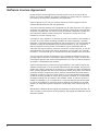
Multi-Drop Controller for BL Series
N-400
N-400
TEST
RS-232C
READER
SD
RD
POWER TIMING
POWER
SD
RD
TERMINATOR
OFF
TERMINATOR
ON
OFF
Specifications are subject to change without notice.
AFFILIATED COMPANIES
KEYENCE CORPORATION
1-3-14, Higashi-Nakajima,
Higashi-Yodogawa-ku, Osaka,
533-8555, Japan
Phone: 81-6-6379-2211
Fax: 81-6-6379-2131
KEYENCE CORPORATION OF AMERICA
Phone: 201-930-0100 Fax: 201-930-0099
KEYENCE ITALIA S.p.A.
Phone: 02-6688220 Fax: 02-66825099
KEYENCE TAIWAN CO., LTD
Phone: 02-2627-3100 Fax: 02-2798-8925
KEYENCE DEUTSCHLAND GmbH
Phone: 06102-36 89-0 Fax: 06102-36 89-10 0
KEYENCE SINGAPORE PTE LTD
Phone: 6392-1011 Fax: 6392-5055
KEYENCE (HONG KONG) CO., LTD
Phone: 3104-1010 Fax: 3104-1080
KEYENCE (UK) LIMITED
Phone: 01908-696900 Fax: 01908-696777
KEYENCE (MALAYSIA) SDN BHD
Phone: 03-2092-2211 Fax: 03-2092-2131
KEYENCE FRANCE S.A.
Phone: 01 56 37 78 00 Fax: 01 56 37 78 0 1
KEYENCE (THAILAND) CO., LTD
Phone: 02-369-2777 Fax: 02-369-2775
KEYENCE INTERNATIONAL TRADING
(SHANGHAI) CO., LTD.
Phone: 021-68757500 Fax: 021-68757550
KOREA KEYENCE CO., LTD.
Phone: 02-563-1270 Fax: 02-563-127 1
© KEYENCE CORPORATION, 1997 0114-4 96M0353 Printed in Japan
RS
SD
RD
RS-455
RS-232C
ON
CS
Software License Agreement
Please read this license agreement carefully and be sure you accept its terms
before you use the software. By using the software you signify that you consent to
be bound by the terms and conditions of this agreement.
Keyence grants to you, and you accept a license to use the programs and the
related materials delivered with this agreement.
The manual and the software are copyrighted with all rights reserved. Your rights of
ownership are subject to the limitations and restrictions imposed by copyright laws.
Under the copyright laws, you may not copy the manual or software, in whole or in
part, without the written consent of Keyence, except in the normal use of the
software or to make a backup copy.
It is illegal to copy, reproduce, or transmit any part of the manual or the software in
any form or by any means (including translation to another language, computer
language, or format)except as permitted by the Copyright law. You are permitted to
write the contents of the software into the machine memory of your computer so
that the software can be executed. The software may be associated with one
computer and may be used by more than one person on that computer, or may be
associated with one person and used by that person on more than one computer.
However, in no event shall two or more persons use the software at the same time.
You may not rent or lease the software, but you transfer the software and accompanying written materials on a permanent basis provided you retain no copies and
the recipient agrees to the terms of this agreement. You may not reverse engineer,
decompile, or disassemble the software.
Keyence warrants that if you discover physical defects in the media on which this
software is distributed, or in the manual distributed with the software, Keyence will
replace the media or manual at no charge to you, provided you return the defective
items, postage prepaid and with proof of purchase, within ninety days of the date of
purchase. Keyence reserves the right to revise this software and manual without
obligation to notify any person of such revision. In no event will Keyence be liable
for loss of profits or goodwill or other indirect, special, incidental, or consequential
damages resulting from any defect in the software, media, or manual. Keyence’s
liability for damages to you or others will in no event exceed the total amount paid
by you for the software. In particular, Keyence shall have no liability for any data
stored in or used with Keyence’s products, including the costs of recovering such
data.
MS Windows, Windows 95 are registered trademarks of Microsoft Corporation. All
other company, product names in this publication are registered trademarks of their
respective owners.
i
Safety Precautions
This instruction manual describes the operation and function of the N-400. Read
this manual carefully to ensure safe use and maximum performance from your N400.
The N-400 can be connected to the BL-700, BL-180 and BL-500 series.
Symbols
The following symbols alert you to important messages. Be sure to read these
messages carefully.
Failure to follow instruction may lead to injury. (electric
WARNING shock, burn, etc.)
CAUTION
Note:
Failure to follow instructions may lead to product damage.
Provides additional information on proper operation.
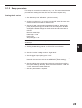
General Precautions
•
At startup and during operation, be sure to monitor the functions and performance of the N-400.
•
We recommend that you take substantial safety measures to avoid any damage
in the event a problem occurs.
•
Do not open or modify the N-400 or use it in any way other than described in
the specifications.
•
When the N-400 is used in combination with other instruments, functions and
performance may be degraded, depending on operating conditions and the
surrounding environment.
•
Do not use the N-400 for the purpose of protecting the human body.
Warnings and Cautions Specific to the N-400
CAUTION
•
To operate the N-400/N-48, use a 24 VDC power supply.
Using a different type of power supply may damage the unit.
•
This unit is a precision instrument and may be damaged if dropped. Be
careful when carrying and mounting the unit.
•
To install this unit, read “Chapter 2, 2.6 Mounting Procedure” in this manual
thoroughly for instructions on proper mounting conditions.
•
For the RS-485 connections, use the recommended cable and follow the
instructions given in this manual. (➮ See “Chapter 2, 2.3.3 Connecting RS-485”
or “Chapter 2, 2.4.5 Connecting RS-485”.) Connecting the RS-485 cable without
following these instructions may cause a communication error.
ii
List of Package Contents
The N-400 includes the following equipment and accessories. Before using the
unit, ensure that all of these items are included with your N-400.
■
•
•
•
N-400 package contents
N-400 (x 1)
User’s Manual (x 1)
N-400 setup software (x 1)
■ N-48 package contents
• N-48 (x 1)
• Instruction manual (x 1)
■ BL-U1 1. package contents
• BL-U1 (x 1)
■ BL-U2 package contents
• BL-U2 (x 1)
1. BL-U1 is not available in Europe. Use BL-U2 instead.
iii
Contents
Chapter 1
Overview of the N-400
1.1
1.2
1.3
Chapter 2
Installation Procedure
2.1
2.2
2.2.1
2.2.2
2.3
2.3.1
2.3.2
2.3.3
2.4
2.4.1
2.4.2
2.4.3
2.4.4
2.4.5
2.5
2.6
2.6.1
2.6.2
2.6.3
2.6.4
Chapter 3
Functions of the N-400 .......................................................................... 2
System Configuration ............................................................................ 4
Part Names ............................................................................................. 5
Installing the N-400 .............................................................................. 10
Connecting N-400 and Wiring ............................................................. 12
Terminals of I/O terminal block and wiring .............................................. 12
Connecting RS-232C .............................................................................. 13
Connecting N-48 and Wiring ............................................................... 16
Connecting the BL series ........................................................................ 16
Terminals of I/O terminal block and connection ...................................... 16
Connecting RS-485 ................................................................................. 19
Connecting BL-U1 and Wiring ............................................................ 21
Connecting power supply ........................................................................ 21
Connecting BL series .............................................................................. 21
Setting BL-U1 DIP switches .................................................................... 22
Terminals of I/O terminal block and wiring .............................................. 23
Connecting RS-485 ................................................................................. 25
Using Connection Test Mode ............................................................. 26
Mounting Procedure ............................................................................ 27
Precautions for mounting environment ................................................... 27
Mounting N-400 ...................................................................................... 28
Mounting N-48 ........................................................................................ 28
Mounting BL-U1 ...................................................................................... 29
N-400 Setup Procedure
3.1
3.2
3.2.1
3.2.2
3.2.3
3.3
3.3.1
3.3.2
3.4
3.5
3.6
Installing Setup Software .................................................................... 32
Setup Software Operating Procedure ................................................ 34
Operating procedure ............................................................................... 34
Description on each setup screen ........................................................... 35
Outline of operation ................................................................................. 36
Details of Operating Procedure ......................................................... 38
Setting procedure .................................................................................... 38
Reading/Saving/Printing File ................................................................... 44
Sending/Receiving Settings ................................................................ 48
Using Terminal ..................................................................................... 52
List of Error Messages ........................................................................ 55
iv
Chapter 4
Multi-Drop Link Mode Control Procedure
4.1
4.1.1
4.1.2
4.2
4.2.1
4.2.2
4.2.3
4.2.4
4.3
4.4
4.4.1
4.4.2
4.5
4.6
Chapter 5
Multi-Head Mode Control Procedure
5.1
5.1.1
5.1.2
5.2
5.2.1
5.2.2
5.2.3
5.3
5.3.1
5.3.2
5.3.3
5.4
5.4.1
5.4.2
5.5
5.6
v
Multi-Drop Link Mode .......................................................................... 58
Controlling multi-drop link mode ............................................................. 58
Setup procedure ..................................................................................... 60
Data Communication in Multi-Drop Link Mode ................................. 61
Auto polling ............................................................................................. 61
Manual polling ......................................................................................... 62
Capacity of Transmission Buffer ............................................................. 63
Handshaking protocol ............................................................................. 65
Command Transmission To BL Series .............................................. 66
N-400 Direct Control Commands ........................................................ 69
Communication procedure ...................................................................... 69
Description of commands ....................................................................... 70
N-400 Setup Command ........................................................................ 75
Communication Time Consideration .................................................. 83
Multi-head Mode ................................................................................... 88
Controlling multi-head mode ................................................................... 88
Setup procedure ..................................................................................... 89
Reading Operation in Multi-Head Mode ............................................. 91
Difference in operation depending on reading mode .............................. 91
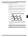
Trigger input signal type .......................................................................... 93
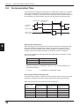
Data transmission timing......................................................................... 94
Data Communication in Multi-Head Mode ......................................... 95
Communication format ............................................................................ 95
Handshaking protocol ............................................................................. 95
Read error code ...................................................................................... 95
Command Communication in Multi-Head Mode ............................... 96
Sending a command to BL series ........................................................... 96
N-400 direct control/setup commands .................................................... 96
Interference Suppression Function ................................................... 97
Communication Time .......................................................................... 98
Chapter 6
PLC Link
6.1
6.1.1
6.1.2
6.2
6.2.1
6.2.2
6.2.3
6.3
6.3.1
6.3.2
6.4
PLC Link ............................................................................................. 102
List of PLCs used for PLC link .............................................................. 102
Devices used for PLC link ..................................................................... 103
Setup Procedure ................................................................................ 104
Setting the BL Series ............................................................................ 104
Setting the N-400 .................................................................................. 105
Setting the PLC ..................................................................................... 106
Device Assignment ............................................................................ 108
Device assignment in multi-drop link mode .......................................... 108
Device assignment in multi-head scan mode ....................................... 113
PLC Link Error .................................................................................... 116
Appendices
Appendix A
Appendix B
Appendix C
Appendix D
Appendix E
Appendix F
Appendix G
Appendix H
Appendix I
Appendix J
Specifications ..................................................................... 120
Dimensions ......................................................................... 122
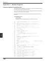
Sample Programs ............................................................... 124
Sample programs for multi-drop link ...................................... 124
Sample program for PLC link ................................................ 126
Troubleshooting ................................................................. 131
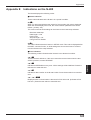
Indications on the N-400 .................................................... 133
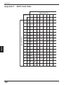
ASCII Code Table ................................................................ 134
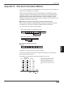
Checksum Calculation Method ......................................... 135
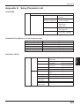
Setup Parameter List .......................................................... 137
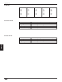
Default Setting List ............................................................. 139
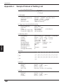
Sample Printout of Setting List ......................................... 140
WARRANTIES
WARRANTIES AND DISCLAIMERS ............................................................ 141
vi
vii
Chapter 1
Overview of the N-400
1.1
Functions of the N-400 ......................................................... 2
1.2
System Configuration .......................................................... 4
1.3
Part Names ............................................................................ 5
Chapter 1
1.1
Overview of The N-400
Functions of the N-400
The N-400 multi-drop controller allows the following functions to be added to the BL
series.
1
Note: The BL-U1 and N-48 can be used as an RS-232C to RS-485 converter.
However, the BL-U1 is not available in Europe.
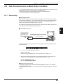
Multi-drop link function (mode)
The N-400 can control up to thirty-one BL series units using a host computer,
enabling the multi-drop link configuration.
The communication path is an RS-485 cable, which provides high noise-resistance
and enables data transmission over a long distance (up to 1.2 km). Since a twisted
pair cable (two cables) is used for the connections, the multi-drop link configuration
can be realized with simple wiring.
The N-400 controls the complicated communication (RS-485 communication)
between each BL series and the N-400. Since the host computer works only for
communication with the N-400, it can be operated with a simple program. (The ID
number assigned to the head of the transmitted data allows you to identify the BL
series unit that sends the data.) Therefore, the host computer’s job is reduced with
this system configuration.
BL series
N-400
RS-232C
N-48
or
BL-U1
*
*
RS-485
Host
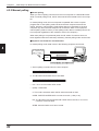
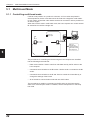
Multi-head scan function (mode)
If the position of bar codes is unknown in a product, or bar codes are printed in
several positions, the bar codes cannot be read with a single bar code reader. In
such cases, several bar code readers need to be mounted in various positions or at
various angles.
When the N-400 controller is used in multi-head scan mode, a host computer can
control several BL series units as if they were a single unit.
N-400
RS-232C
Sensor for
trigger input
N-48
or
BL-U1
Host
BL series
RS-485
2
Chapter 1
Overview of The N-400
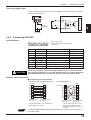
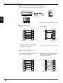
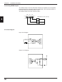
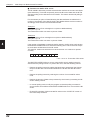
■ Mutual-interference suppression function (in multi-head scan mode)
When several bar code readers are mounted close to each other, for example when
reading multi-stage labels as shown below, the units’ light sources (laser beams)
interfere with each other, affecting the reading stability.
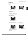
The mutual-interference suppression function allows the BL series’ laser beams to
turn ON sequentially, thus suppressing the mutual interference to ensure stable
readings.
Since the laser beams turn ON sequentially, the duration of laser OFF time (when
each unit is not reading a bar code) becomes longer as the number of connected
units is increased. Therefore, the bar code readers may fail to read bar codes if the
line speed is set too fast.
BL series
N-400
N-48
or
BL-U1
RS-232C
Sensor for
trigger input
Host
RS-485
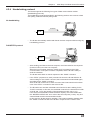
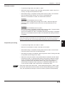
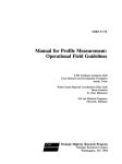
■ PLC link function
In the multi-drop link mode or multi-head scan mode, the PLC link function enables
the BL series’ data to be sent to a PLC without a communication program. Using
this function, you can reduce the number of steps for a PLC program.
No communication program is necessary,
because the N-400 stores the data read by
the BL series directly into the PLCs memory.
N-400
To BL
DM103
DM104
DM105
DM106
4
&30
&31
&32
•
•
•
•
•
•
3
1
Chapter 1
1.2
Overview of The N-400
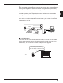
System Configuration
The system configurations using the N-400 controller are as follows:
This section describes multi-drop link mode and multi-head scan mode individually.
1
Multi-drop link mode
•
•
Maximum number of connectable units: 31
Maximum extension distance: 1.2 km
Sensor for
trigger input
N-400 setup
software
for Windows
BL series
N-400
RS-232C
N-48
or
BL-U1
*
*
*
*
RS-485
Host
The N-400 can be connected to the BL-700/BL-500/BL-180 series bar code
readers.
Additional 24 VDC power supply is required for the N-400 and N-48.
Multi-head scan mode (with the interference suppression function)
•
•
Maximum number of connectable units: 31
Maximum extension distance: 1.2 km
N-400 setup
software
for Windows
Sensor for
trigger input
N-400
RS-232C
N-48
or
BL-U1
*
Host
RS-485
*
*
*
4
Connect the sensor for trigger input to the N-400.
The N-400 can be connected to the BL-700/BL-500/BL-180 series bar code
readers.
Additional 24 VDC power supply is required for the N-400 and N-48.
Chapter 1
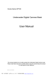
1.3
Overview of The N-400
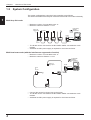
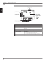
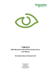
Part Names
N-400
1
N-400
1 Display LEDs
TEST
2 RS-232C port
RS-232C
3 Communication
status indicator LEDs
SD
RD
POWER TIMING
CS
SD
RS
7 RS-485 terminal
RD
RS-455
4 Test switch
6 Power supply terminal
8 Trigger input terminal
TERMINATOR
ON
OFF
5 Terminator switch
ON
OFF
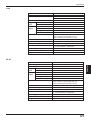
No. Name
1
Display LEDs
Function
• Normally displays “00” (ID number of the N400).
• Displays the ID number of the device being tested.
(➮ See p. 26.)
• Displays “S1 (51)” to indicate setup mode.
(➮ See p. 75.)
• Displays “S0 (50)” to indicate initial communication status
after a setting change. (➮ See p. 48.)
• Displays the N-400’s error condition. (➮ See 131.)
• Displays the ID number of the device currently connected
when sending a hotline command. (➮ See p. 73.)
2
RS-232C port
• Connect a host computer or PLC to this connector.
3
Communication
status indicator LEDs
• POWER: Lit when power is ON.
• TIMING: Lit when the trigger input connected to the N-400
is ON.
(For the RS-232C connections)
Lit when the SD, RD, RS and CS signals are ON.
(For the RS-485 connections)
SD: Lit when the N-400 is sending data.
RD: Lit when the N-400 is receiving data.
* Both the SD and RD indicators are lit when the N-400 is
receiving data.
4
Test switch
Starts the connection test mode.
5
Terminator switch
Switches the terminator’s ON/OFF status.
6
Power supply terminal Connect a 24 VDC power supply.
7
RS-485 terminal
Used for the multi-drop link connection.
8
Trigger input terminal
Used for trigger input in multi-head scan mode.
5
Chapter 1
Overview of The N-400
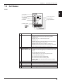
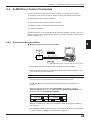
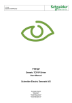
N-48
Note: BL-U1 is not available in the Europe area.
1 READER port
1
READER
2 POWER LED
POWER
SD
RD
6 Communication
status indicator
LEDs
7 Terminator switch
3 I/O terminals
ON
OFF
4 RS-485 terminals
5 Power supply terminals
No. Name
Function
1
READER port
Connect the BL series to this port.
2
POWER LED
Lit when power is ON.
3
I/O terminals
Includes the trigger input terminal and OK/NG output
terminals.
4
RS-485 terminals
Power supply terminals
Used for multi-drop link mode.
Communication status
indicator LEDs
Allows you to monitor the communication status of the
READER port.
5
6
Connect a 24 VDC power supply to these terminals.
SD: Lit when the BL series is sending data.
RD: Lit when the BL series is receiving a command.
7
6
Terminator switch
Turns the terminator ON/OFF.
Chapter 1
Overview of The N-400
BL-U1
Note:
The BL-U1 is not available in Europe
1 OK/NG LED
2 TIMING LED
1
3 Communication status indicator
LEDs
4 POWER LED
5 I/O terminal block
6 Power switch
7 Power supply cable (2 m)
8 RS-232C port
9 READER port
0 DIP switches
No. Name
1
OK/NG LED
Function
• When OK output is ON: The green LED lights.
• When NG output is ON: The red LED lights.
2
TIMING LED
3
Communication status • Allows you to monitor the communication status of the RS232C port.
indicator LEDs
• The SD, RD, RS and CS indicators are provided in this
order from the top.
4
POWER LED
Lit when power is ON.
5
I/O terminal block
Includes the trigger input terminal, OK/NG output terminals,
RS-422A terminal and RS-485 terminal.
6
7
Power switch
Power supply cable
(2 m)
8
RS-232C port
Connect a personal computer to this port. This port is
unused in multi-drop link mode.
9
READER port
Connect the BL series to this port.
0
DIP switche
Switches the communication port, and turns the terminator
ON/OFF.
Lit when trigger input is ON.
Turns the power ON/OFF.
Use a 100 to 240 VAC (50/60 Hz) power supply.
7
Chapter 1
1
8
Overview of The N-400
Chapter 2
Installation Procedure
2.1
Installing the N-400 ............................................................. 10
2.2
Connecting N-400 and Wiring ............................................ 12
2.2.1 Terminals of I/O terminal block and wiring ............................. 12
2.2.2 Connecting RS-232C ............................................................. 13
2.3
Connecting N-48 and Wiring .............................................. 16
2.3.1 Connecting the BL series ....................................................... 16
2.3.2 Terminals of I/O terminal block and connection ..................... 16
2.3.3 Connecting RS-485 ............................................................... 19
2.4
Connecting BL-U1 and Wiring ........................................... 21
2.4.1
2.4.2
2.4.3
2.4.4
2.4.5
Connecting power supply ...................................................... 21
Connecting BL series ............................................................. 21
Setting BL-U1 DIP switches ................................................... 22
Terminals of I/O terminal block and wiring ............................. 23
Connecting RS-485 ............................................................... 25
2.5
Using Connection Test Mode ............................................ 26
2.6
Mounting Procedure ........................................................... 27
2.6.1
2.6.2
2.6.3
2.6.4
Precautions for mounting environment .................................. 27
Mounting N-400 ..................................................................... 28
Mounting N-48 ....................................................................... 28
Mounting BL-U1 ..................................................................... 29
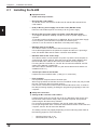
Chapter 2
2.1
Installation Procedure
Installing the N-400
■ Equipment used
• N-400 multi-drop controller
2
•
BL series bar code readers
The N-400 can be connected to the BL-700, BL-500 and BL-180 series bar
code readers.
•
N-48 (or BL-U1) power supply unit for BL series (RS-485 mode)
Each bar code reader requires one N-48 (or BL-U1) power supply.
•
BL-U2 (or BL-U1) power supply unit for BL series (RS-232C mode)
To change the BL series’ settings, one BL-U2 or BL-U1 power supply unit is
required.
To use the N-48 for multi-drop link, an additional BL-U2 24 VDC power supply
unit is required. (The N-48 does not provide an RS-232C port.)
(The BL-U1 can be used as an RS-232C or RS-485 power supply.)
•
RS-232C cable for the N-400
This cable is used to connect the N-400 and the host computer.
Use a cable appropriate for the personal computer and the PLC’s pin assignment. OP-98769 cable and OP-25057 connector are available.
•
RS-232C cable for BL series setup
This cable is used to connect the BL-U2 (or BL-U1) and the host computer to
change the BL series’ settings. Since the wiring of this cable is different from
that of the RS-232C cable for the N-400, both cables must be prepared.
For wiring the BL-U2 and BL-U1, see the “BL-U2 Instruction Manual” and “BL
series User’s Manual”, respectively.
OP-27937 cable is available for BL-U2. (OP-22149 cable and OP-25057 are
available for BL-U1.)
•
Twisted pair cable for the RS-485
Prepare the recommended cable. (➮ See pp. 19, 20 and 25.)
•
Host computer
Use a personal computer with an RS-232C port.
When large quantities of data are sent from several BL series, they may exceed
the host computer’s data processing capacity.
If this occurs, reduce the number of the connected BL series units, or enhance
the data processing capacity (including the programming language) of the host
computer.
■ Setup and connection
1) Setting the BL series bar code readers
Prepare the BL series unit, the BL-U2 (or BL-U1) RS-232C power supply unit,
the RS-232C cable used for setup, and a personal computer. Set up the BL
series using the BL series setup software.
For connection and setup procedures, see the “BL series User’s Manual”.
For the pin assignment of the connection cable between the BL-U2 and the host
computer, see the “BL-U2 Instruction Manual”.
The setting contents vary slightly depending on the mode being used. Refer to
the following pages for more information.
•
•
10
Multi-drop link mode: p. 60
Multi-head scan mode: p. 87
Chapter 2
Installation Procedure
2) Setting the N-400
Prepare the N-400, the RS-232C cable for the N-400, and a personal computer.
Set up the N-400 using the N-400 setup software.
For the setup software operating procedure, see pp. 32 and following.
The setting contents vary slightly depending on the mode being used.
•
•
•
Multi-drop link mode: p. 60
Multi-head scan mode: p. 88
PLC link: p. 102
3) Setting a host computer/PLC
For the RS-232C communication, set the baud rate, data length, parity and stop
bit length according to the settings of the N-400.
To use a PLC link, set up the PLC according to pp. 104 and 105.
4) Connection between the BL series and N-400 (See pp. 19, 20 and 25.)
Connect the N-48 (or BL-U1) power supply unit to the BL series. Then connect
the specified cable (twisted pair cable) between the power supply and the N400. Turn ON the equipment terminator at both ends of the connection.
When using the BL-U1, set the DIP switch to “RS-485”. (See p. 22.)
5) Connection between the N-400 and host computer/PLC (See pp. 13 to 15.)
To connect the N-400 to the host computer or PLC, use the RS-232C cable
whose pin assignment conforms to that of the host computer and PLC.
6) Checking the RS-485 connection between the N-400 and the BL series
The N-400 provides a connection test mode that checks whether the RS-485
connection is correct or not. Using this function, check whether the RS-485
communication can be correctly performed.
For the procedure for using this function, see p. 26.
7) Connecting a sensor for trigger input
Connect a sensor for trigger input to each N-48 or BL-U1 unit. (This sensor is
not required when controlling the BL series’ reading operation using the read
start/end commands.)
To use the BL series in multi-head scan mode, connect a sensor for trigger input
to the N-400. (This sensor is not required when controlling the BL series’ reading operation using the read start/end commands.)
If the sensor for trigger input is directly connected to each BL series, the BL
series cannot operate normally.
8) Checking operation
Using the terminal software included in the N-400 setup software, check
whether the RS-232C communication between the N-400 and host computer
can be performed correctly. (See p. 52.)
To use a PLC link, check whether data is stored in the PLC’s memory.
11
2
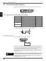
Chapter 2
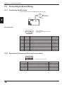
2.2
Installation Procedure
Connecting N-400 and Wiring
This section describes the procedure for connecting the N-400 to external equipment.
TIM COM SG
2
RS-485
+
-
24V DC IN
+
–
24V DC IN
+
–
2.2.1 Terminals of I/O terminal block and wiring
Symbol
Description
Signal direction
TIM
Trigger input
Input
COM
Common terminal for trigger input
Input
RS-485 SG
RS-485 signal ground
–––
RS-485 +
RS-485 + terminal
Input/Output
RS-485 -
RS-485 - terminal
Input/Output
24 VDC OUT
24 VDC power output + terminal
Output
24 VDC power output - terminal
Output
24 VDC IN
24 VDC power input + terminal
Input
24 VDC power input - terminal
Input
* Viewed from the left of the terminal block.
•
The following I-type clips can be used for the connections.
2.0 mm
max.
5 mm max.
6 mm min
Connecting power supply
The N-400 operates with a 24 VDC power supply.
–
24V DC IN
+
–
24V DC IN
+
–
24 VDC
+
When a 24 VDC power supply is connected to the power supply “IN” terminal, the
“OUT” terminal can be used as the 24 VDC power supply output terminal. (Note:
The power supply connected to the “IN” terminal must have a capacity high enough
to supply power to the equipment connected to the “OUT” terminal.)
Using this function, the “OUT” terminal can be used as a 24 VDC power supply for
each BL series connected in the multi-drop link configuration. (For a connection
example, see p. 19.)
CAUTION
To operate the N-400, be sure to use a 24 VDC power supply. Using a power
supply exceeding 24 VDC or using an AC power supply may damage the unit.
If your system must comply with UL regulations, be sure to use the power
supply with NEC class 2 output.
12
Chapter 2
Installation Procedure
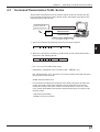
Connecting trigger input
To use multi-head scan mode, connect the trigger input to the N-400 only, instead
of to each BL series unit.
TIM COM SG
Internal circuit
TIM
+
Contact
or solid state
+
+
2
COM
+
15 to 26 VDC
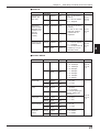
2.2.2 Connecting RS-232C
Pin assignment
13
1
25
14
Pin No.
CAUTION
D-sub 25-pin (male)
DCE specification (defined as terminal)
M2.6 screw
Symbol
Function
1
FG
Frame ground
Signal direction
2
SD (TXD)
Sends data.
Input
3
RD (RXD)
Receives data.
Output
4
RS (RTS)
Ready to send data.
Input
5
CS (CTS)
Request to send data.
Output
6
DR (DSR)
Connected to pin No. 20 inside.
Output
7
SG
Signal ground
20
ER (DTR)
Connected to pin No. 6 inside.
Input
25
+5 V
5 V power supply output (100 mA)
Output
—
—
Pin No. 25 is used for a 5 V power supply output. Do not connect this terminal to the ground terminal or any other terminal when it is unused. Doing this
may damage the N-400 or the external device connected to this terminal.
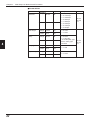
RS-232C cable connections
■ Connecting personal computer
• Connecting the computer with 25-pin
Computer
PC
N-400
FG
1
1
FG
Connector case
1
FG
SD
2
2
SD
RD
2
2
SD
RD
3
3
RD
SD
3
3
RD
RS
4
4
SG
ER
4
4
RS
CS
5
5
RS
SG
5
5
CS
DR
6
6
CS
DR
6
6
DR
SG
7
7
DR
RS
CS
7
7
SG
8
8
CD
1
20 ER
ER 20
D-sub 25-pin (male)
M2.6 screw
20 ER
D-sub 25-pin (male)
M2.6 screw
* The OP-98769 cable (1.5 m: manufactured
by KEYENCE) can be used.
Tips
• Connecting IBM PC
N-400
D-sub 9-pin (female)
#4-40 screw
D-sub 25-pin (male)
M2.6 screw
* The OP-98769 cable (1.5 m: manu
factured by KEYENCE) and the
OP25057 conversion connector can
be used.
A commercially-available straight cable (D-sub 25 pin - 25 pin, or D-sub 25 pin - 9
pin) can be used.
13
Chapter 2
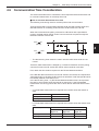
Installation Procedure
■ Connecting KV series/Handheld programmer port
Use the optional cable manufactured by KEYENCE.
N-400
TEST
RS-232C
SD
RD
POWER TIMING
CS
SD
RS
RD
RS-455
TERMINATOR
ON
OFF
OP-24045 (1 m)
or
OP-24025 (5 m)
KV-10, 16, 24
KV-40, 80
OP-96369
2
1. KV-300 and KV-L2 are not available in Europe.
KV-300 1.
■ Connecting KV-L2 1.
Port 1
Terminal block
KV-L2
N-400
KV-L2
N-400
FG
1
1
FG
SD
3
1
FG
SD
2
2
SD
RD
5
2
SD
RD
3
3
RD
3
RD
RS
4
4
SG
4
RS
CS
5
5
RS
5
CS
DR
6
6
CS
6
DS
SG
7
7
DR
20 ER
7 SG
ER 20
D-sub 25-pin (male)
M2.6 screw
20 ER
D-sub 25-pin (male)
M2.6 screw
* The OP-98769 cable (1.5 m: manufactured
by KEYENCE) or a commercially-available
straight cable can be used.
SG
1
Terminal block
D-sub 25-pin (male)
M2.6 screw
1. KV-300 and KV-L2 are not available in Europe.
■ Connecting MELSEC-A series
Connection with AJ71C24, AL71C24-S*,
A0J2-C214S1, AJ71UC24
Link unit
Link unit
N-400
N-400
FG
1
1
FG
Connector case
1
FG
SD
2
2
SD
RD
2
2
SD
RD
3
3
RD
SD
3
3
RD
RS
4
4
RS
ER
4
4
RS
CS
5
5
CS
SG
5
5
CS
DR
6
6
DR
DR
6
6
DR
SG
7
7
SG
RS
CS
7
7
SG
8
8
CD
1
20 ER
CD 8
ER 20
D-sub 25-pin (male)
M2.6 screw
14
Connection with A1SJ71C24-R2/PRF,
A2CCPUC24, A2CCPUC24-PRF,
A1SJ71UC24-R2/PRF
8
20 ER
D-sub 25-pin (male)
M2.6 screw
D-sub 25-pin (male)
M2.6 screw
D-sub 25-pin (male)
M2.6 screw
Chapter 2
■ SYSMAC-C series
Connection with C-200H-LK201(-V1),
C-500-LK203, C-500-LK201-V1, C120LK201-V1
Installation Procedure
Connection with C-20H, C-28H,
C-40H, C-60H, C-80H
PLC
N-400
FG
1
1
FG
FG
1
1
FG
SD
2
2
SD
SD
2
2
SD
RD
3
3
RD
RD
3
3
RD
RS
4
4
RS
RS
4
4
RS
CS
5
5
CS
CS
5
5
CS
SG
7
7
SG
SG
7
7
SG
Link unit
D-sub 25-pin (male)
M2.6 screw
N-400
D-sub 25-pin (male)
M2.6 screw
D-sub 25-pin (male)
M2.6 screw
2
D-sub 25-pin (male)
M2.6 screw
* The OP-98769 cable (1.5 m: manufactured by
KEYENCE) or a commercially-available
straight cable can be used.
Connection with C-200HS(CPU21/23/31/
33), CQM1(CPU21/41/42/43/44), C200HE(CPU42), C200HG(CPU43/63),
C200HX(CPU44/64), C200HWCOM02/
COM04/COM05/COM06
PLC
N-400
FG
1
1
FG
SD
2
2
SD
RD
3
3
RD
RS
4
4
RS
CS
5
5
CS
SG
9
7
SG
D-sub 25-pin (male)
M2.6 screw
D-sub 25-pin (male)
M2.6 screw
■ SYSMAC-CV series
Connection with CV500-LK201(Port 1)
Link unit
FG
1
Connection with CV500LK201(Port 2), CV500, CV1000,
CVM1
PLC
N-400
FG
FG
1
1
FG
2
2
SD
N-400
1
SD
2
2
SD
SD
RD
3
3
RD
RD
3
3
RD
RS
4
4
RS
RS
4
4
RS
CS
5
5
CS
CS
5
5
CS
SG
7
7
SG
SG
9
7
SG
D-sub 25-pin (male)
M2.6 screw
D-sub 25-pin (male)
M2.6 screw
D-sub 25-pin (male)
M2.6 screw
D-sub 25-pin (male)
M2.6 screw
* The OP-98769 cable (1.5 m: manufactured by
KEYENCE) or a commercially-available straight
cable can be used.
15
Chapter 2
2.3
Installation Procedure
Connecting N-48 and Wiring
2.3.1 Connecting the BL series
Connect the BL series to the READER port of the N-48.
BL series
N-48
2
READER
POWER
SD
RD
Pin assignment
1
2
3
4
5
D-sub 9-pin (male)
DCE specification (defined as terminal)
#4-40 screw
6
Pin No.
7
Symbol
8
9
Function
Signal direction
1
TIM
Trigger input
Output
2
RD (RXD)
Receives data.
Output
3
SD (TXD)
Sends data.
Input
4
OK
OK
Input
5
GND (SG)
Ground (Common ground for respective signal)
—
6
NG
NG
Input
7
RS (RTS)
Ready to send data.
Input
8
CS (CTS)
Request to send data.
Output
9
+5 V
5 V power supply output (600mA)
Output
2.3.2 Terminals of I/O terminal block and connections
TIM COM OK NG COM
* Viewed from the left of the unit
16
Symbol
Description
Signal direction
TIM
Trigger input
Input
COM
Common terminal for trigger input
Input
OK
OK output
Output
NG
NG output
Output
COM
Common terminal for output
Output
Chapter 2
RS-485
SG
+
-
24V DC OUT
Installation Procedure
RS-485
24V DC IN
–
+
-
+
SG
* Viewed from the bottom of the unit
Symbol
Description
Signal direction
RS-485 SG
RS-485 signal ground
–––
RS-485 +
RS-485 + terminal
Input/Output
RS-485 -
RS-485 - terminal
Input/Output
24 VDC IN (OUT)
24 VDC power supply input (output) + terminal
Input(Output)
24 VDC power supply input (output) - terminal
Input(Output)
2
• The following I-type clips can be used for connections.
2.0 mm
max.
5 mm max.
6 mm min
Connecting power supply
Connect a 24 VDC power supply to the “IN” terminal.
When a 24 VDC power supply is connected to the “IN” terminal, the “OUT” terminal
can be used as a 24 VDC power supply output terminal. In this case, the “OUT”
terminal can be used as a power supply for other N-48 unit connected in the multidrop link configuration. (➮ For a connection example, see p. 19.)
-
24V DC OUT
24V DC IN
–
+
-
24 VDC
+
CAUTION
•
Do not connect a power supply other than 24 VDC or the unit may be
damaged.
•
Connecting a power supply to the RS-485 terminal may damage the N-48.
•
Do not connect different types of power supplies to the IN and OUT terminals or the unit may not start normally due to the potential difference
between the power supplies.
17
Chapter 2
Installation Procedure
Connecting trigger input
The trigger input allows the BL series to start reading bar codes (turn on the laser
beam).
To connect the BL series in multi-head mode, send the trigger input to the N-400
instead of the N-48.
TIM COM OK
TIM
Internal circuit
2
+
+
+
COM
+
15 to 26 VDC
Connecting OK/NG output
OK NG COM
+
Internal circuit
The OK/NG output indicates the result of the comparison with preset data, or
indicates whether reading is successful or not.
Load
Load
Load
*Rated load: 30 V max. (100mA)
18
+
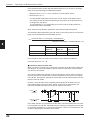
Chapter 2
Installation Procedure
2.3.3 Connecting RS-485
For the RS-485 connections, use the “RS-485 +” and “RS-485 -” terminals provided
on the terminal block.
*
TIM
COM
RS-485 SG
RS-485 +
RS-485 –
24V DC OUT +
24V DC OUT –
24V DC IN +
24V DC IN –
Shield cable
Twisted pair cable
RS-485 SG
RS-485 +
RS-485 –
24V DC IN +
24V DC IN –
2
N-400
24V DC OUT –
24V DC OUT +
RS-485 +
RS-485 –
RS-485 SG
+
24 VDC
N-48
RS-485 SG
RS-485 +
RS-485 –
24V DC IN +
24V DC IN –
24V DC OUT –
24V DC OUT +
RS-485 +
RS-485 –
RS-485 SG
N-48
RS-485 SG
RS-485 +
RS-485 –
24V DC IN +
24V DC IN –
24V DC OUT –
24V DC OUT +
RS-485 +
RS-485 –
RS-485 SG
*
N-48
19
Chapter 2
Installation Procedure
•
The diagram on the previous page shows the connections to supply 24 VDC
power to the N-48 from the power supply connected to the N-400. In this case,
the 24 VDC power supply connected to the N-400 must have a capacity of at
least “140 mA (N-400 current consumption) + 260 mA (N-48 current consumption) x n (Number of N48 units connected)”.
Example
When five N-48 units are connected:
140 mA + 260 mA x 5 = 1.44 A
Use a power supply with at least 1.44 A capacity.
2
Note: The RS-485 cable can be extended up to 1.2 km. With the power supply
cable, however, the 1.2 km extension is not guaranteed.
To extend the power supply cable as shown in the connection diagram on the
previous page, ensure that the power voltage supplied to all the N-48 units is within
the range of 24 VDC -20% to +10%.
•
To connect a 24 VDC power supply to each N-48 unit, remove the 24 VDC
wiring shown in the previous page. To connect the power supply, use the following cable.
Recommended RS-485 cable
• 0.75 mm2 x 2 cores, sheilded
•
Up to thirty-one N-48 (BL series) units can be connected in multi-drop link mode.
•
The total extension length of the RS-485 cable must be within 1.2 km.
•
Turn ON the equipment terminator (termination resistance: 100 Ω) at both ends
of the RS-485 connection (marked with * in the figure above).
•
Turn ON/OFF the N-48 terminator using the terminator switch. (➮ See p. 7.)
•
Turn ON/OFF the N-400 terminator using the terminator switch. (➮ See p. 6.)
Note: Be sure not to connect the RS-485 cable using the terminal block.
Incorrect
Correct
Note 1: Do not place the RS-485 cable in the same conduit as a power cable.
Note 2: Do not branch the RS-485 connection as shown below.
Incorrect
(Connection with branch)
N-48
N-48
C orrect
(Connection without branch)
N-400
N-48
N-48
N-400
*
*
N-48
N-48
* Terminator ON
20
Chapter 2
2.4
Installation Procedure
Connecting BL-U1 and Wiring
To use the BL-U1 AC power supply, connect it as described below.
2.4.1 Connecting power supply
Plug the BL-U1 power cable into an outlet.
2
FG line
CAUTION
Use a power supply of 100 to 240 VAC ± 10% (50/60 Hz).
2.4.2 Connecting BL series
Connect the BL series to the READER port of the BL-U1.
BL-U1 READER port pin assignment
1 2 3 4 5
6 7 8 9
Pin No.
D-sub 9-pin (male)
DCE specification (defined as terminal)
#4-40 screw (female)
Symbol
Function
1
TIM
Trigger input
Signal direction
Output
2
RD (RXD)
Receives RS-232C data.
Output
3
SD (TXD)
Sends RS-232C data.
Input
4
OK
OK
Input
5
GND (SG)
Ground (Common ground for respective
signal)
—
6
NG
NG
Input
7
RS (RTS)
Ready to send RS-232C data.
Input
8
CS (CTS)
Request to send RS-232Cdata.
Output
(Control method can be selected with the DIP
switches. See p. 22.)
9
+5 V
+5 V power supply (1.5 A)
Output
21
Chapter 2
Installation Procedure
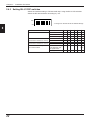
2.4.3 Setting BL-U1 DIP switches
Switch the interface setting to “RS-485 multi-drop” using the BL-U1 DIP switches.
Switch the RS-485 terminator according to p. 25.
OFF
ON
* The figure on the left shows the default settings.
1
2
3
4
5
6
2
DIP Switch No.
Interface selection
22
1
2
3
RS-232C
ON OFF OFF
RS-422A
OFF ON OFF
RS-485 multidrop
OFF OFF ON
4
5
6
RS-422A terminator
OFF
OFF
(Termination resistance: 100 Ω)
ON
ON
RS-485 terminator
OFF
OFF
(Termination resistance: 100 Ω)
ON
ON
Selection of READER port
CS control method
ON or OFF according
to the RS-232C port
CS signal status.
OFF
Normally ON
ON
Chapter 2
Installation Procedure
2.4.4 Terminals of I/O terminal block and wiring
TIM
Trigger
input
+12V OUT– COM
OK
NG
SDA
SDB
Power supply
OK/NG output
for sensors
(12 VDC, 300 mA)
SG
RDA
RDB
RS-422A/RS-485
Symbol
Description
Signal direction
TIM
Trigger input
Input
+12 V OUT
+ terminal of power supply for sensor (12 VDC, 300 mA) Output
– terminal of power supply for sensor (0 V)
Output
COM
Common terminal for OK/NG output
—
OK
OK output
Output
NG
NG output
Output
SDA
+ terminal for RS-422A data transmission/
RS-485 + terminal
Output,
Input/Output
SDB
– terminal for RS-422A data transmission/
RS-485 - terminal
Output,
Input/Output
SG
Signal ground
—
RDA
+ terminal for RS-422A data reception
Input
RDB
– terminal for RS-422A data reception
Input
Input
* Viewed from the left of the terminal block
• M3.0 screws are used for the terminal block.
• Use the following crimp terminals for connections.
Round-shape
6.0 mm or
less
Fork-shape
6.0 mm or
less
Connecting trigger input
The trigger input allows the BL series to start reading bar codes (turn on the laser
beam).
The trigger input is turned ON when 8.5 to 30 VDC input is activated between the
trigger input terminals.
The BL-U1 power supply for the sensor can be used as the input power supply.
TIM
+12V OUT–
Contact or
solid-state
+
+
8.5~30VDC
23
2
Chapter 2
Installation Procedure
Connecting OK/NG output
The OK/NG output is used to differentiate between acceptable and unacceptable
results based on the comparison with the preset data, and to indicate whether or
not the BL series successfully read bar codes.
The OK/NG output is an open-collector output.
COM
OK
NG
*Rated load: 30 V max. (100 mA)
2
Load
Load
+
I/O circuit diagram
3.3KΩ
TIM
2.4
KΩ
Internal circuit
Input circuit diagram
Internal circuit
Output circuit diagram
OK/NG
COM
24
Load
+
Chapter 2
Installation Procedure
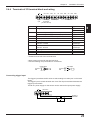
2.4.5 Connecting RS-485
For the RS-485 connections, use the “SDA” and “SDB” terminals provided on the
terminal block.
*
*
N-400
BL-U1
BL-U1
BL-U1
SDA
SDA
SDA
RS-485 +
SDB
SDB
SDB
RS-485 –
SG
SG
SG
RS-485 SG
2
Recommended RS-485 cable
• 0.75 mm2 x 2 cores, shielded
•
Up to thirty-one BL-U1 (BL series) units can be connected in multi-drop link
mode.
•
The total extension length of the RS-485 cable must be within 1.2 km.
•
Turn ON the equipment terminator (termination resistance: 100 Ω) at both ends
of the RS-485 connection (marked with * in the above diagram).
•
Turn ON/OFF the BL-U1 terminator using the terminator switch. (See p. 22.)
•
Turn ON/OFF the N-400 terminator using the terminator switch. (See p. 6.)
Note: Be sure not to connect the RS-485 cable using the terminal block.
Incorrect
Correct
BL-U1
BL-U1
Note 1: Do not place the RS-485 cable in the same conduit as a power cable.
Note 2: Do not branch the RS-485 connection as shown below.
Incorrect
(Connection with branch)
BL-U1
BL-U1
Correct
(Connection without branch)
N-400
BL-U1
BL-U1
N-400
*
*
BL-U1
BL-U1
* Terminator ON
25
Chapter 2
2.5
Installation Procedure
Using Connection Test Mode
This section describes the procedure for performing a connection test after the N400 and the BL series (N-48 or BL-U1) are connected with the RS-485 cable.
Note: To use the connection test mode, ensure that the settings of the connected
BL series and those of the N-400 are switched to “multidrop link” mode.
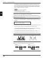
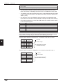
1) When you press and hold the N-400 test switch for approximately 2 seconds
after the power to all devices is turned ON, the connection test mode is activated. The N-400 displays the ID number of the device being tested. If the
devices are properly connected, the ID number is automatically incremented.
2
2) If any device is not connected or is improperly connected, the ID number
corresponding to the device flashes.
To go to the next step during the connection test, press the test switch once.
Example 1
When ten BL series (ID Nos. 1 to 10) are connected:
The displayed ID number automatically changes from “1” to “10”, and then “11”
will flash if the connection test result is “OK”.
Example 2
When fourteen BL series (ID Nos. 3 to 16) are connected:
When “1” flashes, press the test switch once. When “2” flashes, press the test
switch again. The displayed number changes from “3” to “16”, and then “17” will
flash if the connection test result is “OK”.
3) If an ID number of any BL series flashes, the BL series unit is not properly
connected. After checking the following points, perform the connection test
again.
•
Check that the RS-485 communication parameters (baud rate, data length,
parity and stop bit length) of the N-400 match to those of the BL series.
•
Check that the BL series is set to “multi-drop link” mode.
•
Check that all cables are properly connected. Ensure that the connections are
not branched and that no cables are connected using the terminal block. (➮
See pp. 19, 20 and 25.)
•
Check that the equipment terminators at both ends of the connection are ON
and the terminators of other equipment are OFF.
•
Check that the BL series’ ID numbers are properly assigned. Make sure that the
same ID number is not assigned to different devices.
4) Pressing and holding the test switch for approximately 2 seconds again resets
the connection test mode.
26
Chapter 2
2.6
Installation Procedure
Mounting Procedure
2.6.1 Operating environment precautions
CAUTION
This unit is a precision instrument and you must take care in choosing the
operating environment.
■ Ambient environments
Do not install the unit in place as shown below
2
•
The unit is exposed to direct sunlight, or the ambient temperature may fall
below 0°C (32°F) or exceed 50°C (122°F);
•
The relative humidity may exceed the range of 35 to 85%, or condensation may
occur due to rapid temperature changes;
•
Corrosive gas or inflammable gas is present, or a high level of dust, salt, iron
particles or soot is present;
•
The unit is subject to vibration or impact;
•
Water, oil or chemicals may splash the unit;
•
A strong magnetic field or electric field is generated.
•
Do not place the cables in the same conduit as a power cable.
■ In-panel installation
To mount the N-400 in a panel, carefully observe the following instructions.
•
Provide enough ventilation space.
•
If the ambient temperature may fall below 0°C (32°F) or exceed 50°C (122°F),
provide a fan or air conditioner.
•
Do not mount this unit in a panel where a high voltage device is installed.
•
Place this unit as far away from power lines as possible.
27
Chapter 2
Installation Procedure
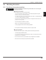
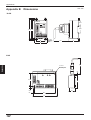
2.6.2 Mounting N-400
To mount the N-400, you can use one of the following two methods:
Direct mounting
Pull the brackets provided at four positions on the rear of the N-400, and fix them
with screws.
N-400
2
TEST
RS-232C
SD
100
CS
RD
RS
RD
SD
POWER TIMING
RS-455
TERMINATOR
ON
OFF
4 x ø5
mounting hole
40
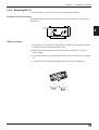
DIN-rail mounting
To mount the N-400 on a DIN-rail, press the unit against the DIN rail until it clicks.
To remove the unit, pull the hook in the direction indicated by arrow.
N-400
TEST
RS-232C
SD
RD
POWER TIMING
CS
SD
RS
RD
RS-455
TERMINATOR
ON
OFF
2.6.3 Mounting N-48
To mount the N-48, use the mounting hole.
4 x ø5
mounting hole
POWER
43.2
5.9
5.9
28
63.2
75
SD
RD
Chapter 2
Installation Procedure
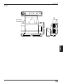
2.6.4 Mounting BL-U1
To mount the BL-U1, you can use one of the following two methods:
Positions of direct mounting
Pull the brackets provided at four positions on the rear of the BL-U1, and fix them
with screws.
4 x ø5
2
98
150
DIN-rail mounting
1. Hook the BL-U1 in the groove of the DIN rail from the top, and press the bottom
of the BL-U1 against the DIN rail until it clicks.
2. Make sure that the DIN-rail mounting hook is set in condition “A”. If it is not,
push it inward.
3. To remove the BL-U1 from the DIN rail, pull the hook so that it is set in condition
“B”.
4. To mount the unit on the DIN rail again, restore the hook to condition “A”.
A
B
29
Chapter 2
2
30
Installation Procedure
Chapter 3
N-400 Setup Procedure
3.1
Installing Setup Software ................................................... 32
3.2
Setup Software Operating Procedure ............................... 34
3.2.1 Operating procedure .............................................................. 34
3.2.2 Description on each setup screen ......................................... 35
3.2.3 Outline of operation ............................................................... 36
3.3
Details of Operating Procedure ........................................ 38
3.3.1 Setting procedure .................................................................. 38
3.3.2 Reading/Saving/Printing File ................................................. 44
3.4
Sending/Receiving Settings .............................................. 48
3.5
Using Terminal .................................................................... 52
3.6
List of Error Messages ....................................................... 55
Chapter 3
3.1
N-400 Setup Procedure
Installing Setup Software
The N-400 includes the setup software for the Windows version only.
The operating environments and the procedure for installing this setup software
are described below.
■ Hardware requirments
• IBM PC/AT 100% compatible
CPU: 80386 or higher
Memory:
4 MB or more
Floppy disk drive: 3.5 inch floppy disk drive (1.44 Mb compatible)
Serial port: A minimum of one RS-232C port is required.
■ OS requirements
• MS-Windows 3.1 or MS-Windows 95
3
Installation procedure
1. Insert the N-400 setup software system disk into the floppy drive.
2. Perform the following procedure.
•
Windows 3.1:
Execute “Run” in the icon menu of the program manager.
•
Windows 95:
Select “Run” from the "Start" menu.
3. Run the “SETUP” file from the floppy disk drive.
(This step is common to both the Windows 3.1 and Windows 95.)
Type in as follows:
A: \SETUP
32
Chapter 3
N-400 Setup Procedure
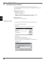
4. The N-400 setup software installer starts. Follow the instructions in the install
window. (Typically, the installation procedure can be completed simply by
pressing [Next (N)] twice.)
5. The setup software is normally installed in the following directory:
C: \KEYENCE\N400
If this directory is correct, click on [Next (N)]. If you wish to change the directory,
click on [Browse (R)..], and select the desired directory.
6. When installation starts, the file copy process is displayed as a graph. When the
installation is completed, the following message appears.
3
7. For Windows 3.1, double-click on the [N400] icon in the [KEYENCE] group to
start the setup software.
For Windows 95, start the program from the "Start" menu.
33
Chapter 3
3.2
N-400 Setup Procedure
Setup Software Operating Procedure
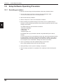
3.2.1 Operating procedure
To set up the N-400 using the setup software, follow the procedure below.
1. Connect the N-400 to the host computer using the RS-232C cable.
➮ For the recommended cable, see 2.2.2 Connecting RS-232C.
2. Start the N-400 setup software.
3. Select a setup item, and set it to the desired condition.
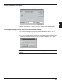
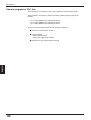
4. Before sending the updated settings to the N-400, click on [COM PORT] to
match the communication parameters of the personal computer with the current
settings of the N-400.
3
The default settings of the N-400 are as follows:
• Baud rate: 9600 bit/s
• Data length: 7 bit
• Parity: Even
• Stop bit length: 1 bit
Immediately after you purchase the N-400, set [COM PORT] to the above
settings.
If you do not know the current settings of the N-400, press the N-400 test switch
for approximately 5 seconds. When the N-400 displays “S0(50)”, the N-400 is
automatically set to the above settings. The N-400 can communicate with the
host computer if the “COM PORT” settings are same as the above.
5. Click on [Transfer] to send the updated settings to the N-400.
(The current settings of the N-400 can also be read.)
6. Select [FILES] to save or print the settings, as required.
7. After the setup procedure is completed, click on [Exit] to close the setup software.
34
Chapter 3
N-400 Setup Procedure
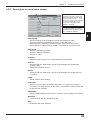
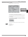
3.2.2 Description on each setup screen
▼
▲
Displays the name of the setup file
currently being edited. If the file has
been read from the setup file, the file
name is specified as “File: ...”. If the
file has been read from the N-400, the
file name is marked with “N-400”. If
the file name is the initial setting,
“default” is displayed.
If the file name has been changed
from the initial setting (the condition
immediately after it is read from the
file), “changed” is displayed.
3
HOST MODE:
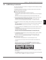
• Sets auto-polling mode (multi-drop link) and multi-head scan mode
• Sets the interference suppression function in multi-head mode
• Sets read mode, measuring method and trigger input in multi-head mode
• Sets a read error code and trigger ON/OFF commands in multi-head mode
PROTOCOL:
• Sets the handshaking protocol
• Sets the header and delimiter
• Sets the PLC link
ID SETUP:
• Registers the ID number of the connected BL Bar Code Reader
RS-232C:
• Sets the baud rate, data length, stop bit length and parity for the RS-232C
communication
• Setting the RTS/CTS protocol
RS-485:
• Sets the baud rate, data length, stop bit length and parity for the RS-485 communication
FILES:
• Saves, reads or prints settings
COM PORT:
• Sets the communication parameters (baud rate, etc.) of the host computer
according to the settings of the N-400 before communication starts between the
N-400 and host computer.
TRANSFER:
• Sends updated settings to the N-400, or reads the current settings of the N-400.
MONITOR:
• Checks if the N-400 can operate normally.
EXIT:
• Quits the N-400 setup software.
35
Chapter 3
N-400 Setup Procedure
3.2.3 Outline of operation
This section describes the basic operations of the N-400 setup software.
To enter settings, place the mouse pointer on the item to be changed, and click the
left mouse button.
Mouse pointer
Clicking on
• • •
Used to select the item to be changed.
3
Clicking on
Used to select any of several options.
The selected item is marked with • .
Clicking on
Used to select whether to enable or disable this function.
To enable this function, the
mark is checked with “√”. (For the Windows Ver. 3.1,
it is checked with “x”.)
➞
Clicking on
Used to select any of several options.
36
Chapter 3
N-400 Setup Procedure
Entering a value
After clicking in the frame, enter a value using the keyboard.
If the entered value exceeds the setting range, an error message is displayed.
(➮ See p. 55.)
Entering characters
When you click in the frame labeled “ASC”, you can enter characters using the
keyboard.
When you click in the frame labeled “HEX”, you can enter characters using hexadecimal numbers (00 to 7F). This function is used to enter control characters (00 to
21h ASCII codes, such as [CR] and [STX]).
37
3
Chapter 3
3.3
N-400 Setup Procedure
Details of Operating Procedure
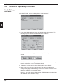
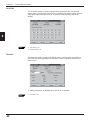
3.3.1 Setting procedure
HOST MODE
In the HOST MODE, select “Multi-drop link” or “Multi-head scan”.
3
1. If you select “Multi-head scan” mode, the following setup items appear. The
following steps are effective for “Multi-head scan” mode only.
2. To use the “Interference Suppression” function, the following setup items
appear.
“TIMER” indicates the reading time of each BL series in the interference suppression mode. Enter a value using the keyboard.
3. “Data-send” is displayed only when “Read mode” is set to “Single”.
4. Enter a read error code using the keyboard. The read error code can be
changed to any eight character string. Set this code so that it conforms to the
read error code of the connected BL series.
Normally, you should use the default setting (ERROR) without changing it (as
well as the BL series’ read error code).
38
Chapter 3
N-400 Setup Procedure
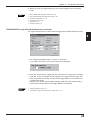
5. When you click on [Trigger setup], you can set the trigger input in multi-head
mode.
Tips
➮
MULTI-DROP LINK (Multi-drop link mode): p. 58
➮
MULTI-HEAD SCAN (Multi-head scan mode): p. 86
➮
Interference Suppression: p. 95
➮
Read mode: pp. 89 to 90
➮
Data-send: p. 92
➮
Read error code: p. 93
TRIGGER SETUP (only when Multi-head scan is selected)
The Trigger Setup screen is used to set the trigger input for Multi-head scan mode.
3
1. Set “Trigger Input/Signal Type” to “Level” or “One-shot”.
If you select “One-shot”, the one shot input time is displayed.
2. Enter the “Command for Trigger ON” and “Command for Trigger OFF” using the
keyboard. These commands can be changed to any eight character string. Set
these commands so that they conform to the trigger ON/OFF commands of the
connected BL series.
Normally, you should use the default settings (LON and LOFF) without changing them (as well as the BL series’ trigger ON/OFF commands).
Tips
➮
Trigger Input/Signal Type: p. 91
➮
Command for Trigger ON, Command for Trigger OFF: p. 72
39
Chapter 3
N-400 Setup Procedure
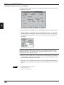
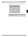
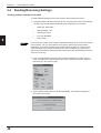
PROTOCOL (when "Use PLC" is disabled)
The PROTOCOL screen is used to set “Handshaking protocol” and various items
to enable the "Use PLC".
3
1. When “Use PLC” is disabled, set the “Handshaking protocol” as shown above.
2. Select “Header” and “Delimiter” from the displayed items. You can change the
read data format by setting these items. If you select “Custom”, the following
screen appears. These items can be set to any five character string using the
keyboard.
Note: When customizing the header and delimiter, you modify them based on the
previously selection. When selecting "custom," if you currently use "CR", "0D"
appears in hex and "." in ASCII (It is not a period but stands for "CR"). If "none"
was used previously, nothing appears.
3. Normally, the ID number of the BL series that executed reading is not added to
the read data in multi-head scan mode. However, you can set “Add ID” so that
the ID number is added to the read data.
4. “Checksum” can be added to read data to check incompatible data translation
between the N-400 and the host computer. Normally, this function is not necessary.
Tips
40
➮
Handshaking protocol: pp. 65 and 66
➮
Header, Delimiter: p. 61
➮
Checksum: pp.133 and 134
Chapter 3
N-400 Setup Procedure
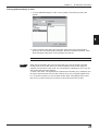
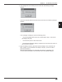
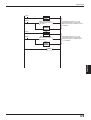
PROTOCOL (when "Use PLC" is enabled)
To enable the "Use PLC", set each item as follows:
S018
The setting of the station
number is not displayed
when “KV Series” is selected.
▼
▼
The setting of the file register
is displayed only when
“MELSEC-A” is selected.
1. Set “Connected PLC”, “DM head address” and “Station No.”.
To set “DM head address”, enter a value (0000 to 9900) using the keyboard.
2. To send a trigger signal to the BL series when the PLC link is enabled, set
“PLC trigger area”.
3. To use “File Register”, set “File Register” to “Enable”. When “File Register” is
enabled, the following screen appears. The “File Register” can be used with
the Mitsubishi MELSEC-A series only.
Enter the block number (000 to 255) of the file register using the keyboard.
Tips
➮
PLC link: p. 100
➮
PLC trigger area: p. 106
➮
DM head address: p. 106
➮
File register: p. 101
41
3
Chapter 3
N-400 Setup Procedure
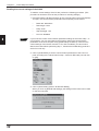
ID SETUP
The ID SETUP screen is used to register the ID numbers of the connected BL
series. When you register the ID numbers in multidrop link mode, polling automatically starts when the N-400 starts up. To perform manual polling, skip the ID
SETUP.
3
Tips
➮
Auto polling: p. 61
➮
Manual polling: p. 62
RS-232C
The RS-232C screen is used to set the RS-232C communication parameters for
the N-400. Set these parameters so that they conform to those of the host computer or PLC.
1. Setting “RTS/CTS” is disabled when “Use PLC” is selected.
Tips
42
➮
RTS/CTS: p. 66
Chapter 3
N-400 Setup Procedure
RS-485
The RS-485 screen is used to set the RS-485 communication parameters for the
N-400. Set these parameters so that they conform to those of the connected BL
series.
3
Note: We recommend that you set the baud rate to “38400 bits/s” to increase the
processing speed, since the RS-485 communication between the N-400 and the
BL series transfers a large volume of data.
43
Chapter 3
N-400 Setup Procedure
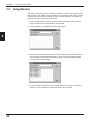
3.3.2 Reading/Saving/Printing File
The FILES screen is used to save updated settings in a file, to read a saved setting
file, and to print the contents of a setting file.
3
•
Open: Reads a saved setting file.
•
Save: Saves updated settings in a file.
•
Compare: Compares the settings currently edited with a file previously saved.
•
Print: Prints contents of a setting file.
•
Default (Initialize settings): Restores updated settings to the default settings.
•
Version info: Displays the version information of this software.
Reading a previously saved setting file
1. To read a previously saved setting file, click on [Open]. The following screen will
appear.
2. When you click on [OK] after selecting a file, the selected file can be opened.
44
Chapter 3
N-400 Setup Procedure
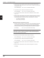
Saving updated settings in a file
1. To save updated settings in a file, click on [Save]. The following screen will
appear.
3
2. Click on the file name entry field, and enter a file name using the keyboard.
Specify a file name within eight characters. Be sure to add the extension “NCF”.
After entering the file name, click on [OK] to save the file.
Note: This software cannot accept a long file name in Windows 95.
Tips
When the saved setting file is sent to the N-400, the name of the file is simultaneously sent to the N-400. When you read the settings of the N-400 using this
software, the file name is also read. It is convenient for maintenance since you can
find the file that stores the settings.
To enter a file name, use alphanumerics (letters and numbers) only. Otherwise, the
file name cannot be sent to the N-400, because it can only recognize alphanumerics. To send a file name, be sure to enter the file name using alphanumerics and
then save it. (If the file name is not saved, it cannot be sent to the N-400.)
45
Chapter 3
N-400 Setup Procedure
Comparing the settings currently edited with a saved file
1. To compare the settings currently edited with the setting file previously saved,
click on [Compare].
3
2. Select a file to be compared, and click on [OK]. Then, the system compares the
selected file with the settings currently edited, and displays the result.
Matched
46
Not matched
Chapter 3
N-400 Setup Procedure
Printing contents of a setting file
1. To print settings, click on [Print]. The following screen will appear.
3
2. Adjust “Printer Setup” as required, and click on [OK]. Printing will then start.
Restoring the settings currently edited to the default (initial) settings
1. To restore the settings currently being edited to the default settings, click on
[Default (Initialize settings)].
2. If you try to initialize the settings currently being edited without saving them, the
following message appears. If you wish to execute initialization, click on [OK].
Note: The initialization procedure described in this section is used to initialize the
settings being edited with the setup software. The settings on the N-400 cannot be
initialized.
47
Chapter 3
3.4
N-400 Setup Procedure
Sending/Receiving Settings
Sending updated settings to the N-400
To send updated settings to the N-400, perform the following procedure.
1. Press and hold the N-400 test switch for five seconds. When the N-400 displays
“S0 (50)”, the communication parameters are temporarily set as follows:
3
Tips
•
Baud rate: 9600 bits/s
•
Step bit length: 1 bit
•
Data length: 7 bits
•
PLC link: Disabled
•
Parity: Even
If you know the current communication parameter settings of the N-400, this step is
not necessary. You can send data to the N-400 by setting the communication
parameters of the host computer using [COM PORT] so that they conform to the
current settings of the N-400. However, if PLC link is enabled, you cannot send
data to the N-400 without performing this step because the handshaking protocol is
set for PLC link only.
2. Click on [COM PORT] to set the communication parameters of the host computer according to the values listed in the step 1. (above procedure). Select an
RS-232C port, and click on [OK].
3. Click on [Send setting (Save in N-400 EEP-ROM]. The updated settings are
then sent to the N-400.
48
Chapter 3
N-400 Setup Procedure
4. If the settings were successfully sent to the N-400, the following message
appears.
If the host computer failed to send the data to the N-400, the following message
appears.
3
If this message is displayed, check the following points:
•
•
•
Check that [COM PORT] is set to the values listed in step 1. when the N400 displays “S0 (50)”.
Check that the power to the N-400 is ON.
Check that the RS-232C cable pin assignment of the N-400 is the same as
that of the host computer.
5. After the settings are sent, press the N-400 test switch once to reset the “S0
(50)” condition. (If the N-400 does not display “S0 (50)”, you do not need to
press the test switch. )
When the N-400 displays “00”, the sending procedure is completed. (The
communication parameters of the N-400 are set to the updated settings.)
49
Chapter 3
N-400 Setup Procedure
Reading the current settings of the N-400
To read the current settings of the N-400, perform the following procedure. (This
procedure is almost the same as the procedure for sending settings.)
1. Press and hold the N-400 test switch for five seconds. When the N-400 displays
“S0 (50)”, the communication parameters are temporarily set as follows:
3
Tips
•
Baud rate: 9600 bits/s
•
Data length: 7 bits
•
Parity: Even
•
Step bit length: 1 bit
•
PLC link: Disabled
If you know the current communication parameter settings of the N-400, step 1. is
not necessary. You can send data to the N-400 by setting the communication
parameters of the host computer using [COM PORT] so that they conform to the
current settings of the N-400. However, if PLC link is enabled, you cannot send
data to the N-400 without performing step 1., because the handshaking protocol is
set for PLC link only.
2. Click on [COM PORT] to set the communication parameters of the host computer according to the values listed in step 1. Select an RS-232C port and click
on [OK].
3. Click on [Send setting (Save in N-400 EEP-ROM)].
When you click on [Read N-400 settings], the settings of the N-400 can be read
on the host computer.
50
Chapter 3
N-400 Setup Procedure
4. If the settings of the N-400 were successfully read, the following message
appears.
If the host computer failed to read the data, the following message appears.
3
If this message is displayed, check the following points:
•
•
•
Check that [COM PORT] is set to the values listed in step 1. when the N400 displays “S0 (50).”
Check that the power to the N-400 is ON.
Check that the RS-232C cable pin assignment of the N-400 is the same as
that of the host computer.
5. After the settings are read, press the N-400 test switch once to reset the “S0
(50)” condition. (If the N-400 does not display “S0 (50)”, you do not need to
press the test switch. )
When the N-400 displays “00”, the reading procedure is completed.
51
Chapter 3
3.5
N-400 Setup Procedure
Using Monitor
This setup software provides the “Monitor” program to check if the N-400 can send
data properly. The “Monitor” program allows you to display the data read by the BL
series on the host computer’s monitor screen, and also to send a command from
the host computer to the N-400 or BL series.
1. Click on [COM PORT] to set the communication parameters of the host computer according to the current settings of the N-400.
2. Click on [Monitor]. The MONITOR screen will appear.
3
3. When the BL series reads bar codes, the data read by the BL series is listed on
the screen (in the [Received Data] field). A record of up to 1000 lines of data
can be obtained. Using the scroll bar at the right of the [Received Data] field,
you can see the previous data.
4. If you click [Stop], received data is not listed. (The button name is changed to
[Start].) If you try to display received data again, click on [Start].
52
Chapter 3
N-400 Setup Procedure
5. When you enter a command in the “Send command” field, you can send
the command to the N-400 (or BL series). The format of the command to
be sent is “[Command] + [CR]”. Typing command and pressing [ENTER]
key sends the command.
3
6. When you click on the [ARROW] button in the “Send command” field, the
commands previously sent are listed. (Up to 100 commands can be listed.)
7. Click on [Quit] to quit this mode.
Procedure for starting BL test mode using the “Monitor” screen
To start the BL series “Reading rate check” mode by sending a command
from the host computer to the N-400 in multidrop link mode, send the command using the “Monitor” screen according to the procedure below.
■ Using the N-400 in multi-drop link mode
1. Send the “Specific ID polling” command (see p. 72) so that polling is
performed only for the BL series to be tested. To send the command using
the Monitor screen, be sure to enter the command using uppercase
characters. [CR] of the following command corresponds to the [Enter] key
of the personal computer.
POLEmm[CR]
* mm = 01 to 31 (ID number of BL series)
Note: When only a few BL series units are connected, you need not send this
command. However, when many BL series units are connected, the cycle of
the N-400’s polling for each BL series becomes longer than the reading cycle
of the test mode, causing the data to be stored in the N-400 buffer. To prevent
this, be sure to send the above command.
53
Chapter 3
N-400 Setup Procedure
2. Send the test mode command to the BL series to be tested. When the test
mode is started, data read by the BL series is listed in the [Received Data] field
of the Monitor screen.
%Tmm-TEST1[CR]
* mm = 01 to 31: ID number of BL series
3. To quit the test mode, send the test mode end command.
%Tmm-QUIT[CR]
* mm = 01 to 31: ID number of BL series
4. To continue the test mode with a BL series of a different ID number, repeat
steps 1. to 3.
5. When you finish using the test mode, reset the “Specific ID polling” command. If
the auto polling mode is selected, send the “Auto polling ON” command. If the
manual polling mode is selected, send the “Auto polling OFF” command.
3
•
•
Auto polling: POLE00[CR]
Manual polling: POFF[CR]
■ Using the N-400 in multi-head scan mode
1. Send the “Specific ID polling” command (see p. 72) so that polling is performed
only for the BL series to be tested. To send the command using the Monitor
screen, be sure to enter the command using uppercase characters. [CR] of the
following command corresponds to the [Enter] key of the personal computer.
POLEm[CR]
* mm = 01 to 31 (ID number of BL series)
Note: In multi-head scan mode, the N-400 performs polling only when the BL
series read bar codes. Therefore, to use the test mode, you need to send the
“Polling ON” command or “Specific ID polling” command before starting the test
mode so that polling is always enabled.
2. Send the test mode command to the BL series to be tested.
%Tmm-TEST1[CR]
* mm = 01 to 31: ID number of BL series
3. To quit the test mode, send the test mode end command.
%Tmm-QUIT[CR]
* mm = 01 to 31: ID number of BL series
4. To continue the test mode with a BL series of a different ID number, repeat
steps 1. to 3.
5. When you finish using the test mode, send the “Polling OFF” command.
POFF[CR]
54
Chapter 3
3.6
N-400 Setup Procedure
List of Error Messages
Error message
Errors
during
setup
Errors
communication
Errors file
editing
Contents
“Timer value incorrect. [OK]”
The setting of the trigger ON time exceeds
the range of 1 to 255 (x10 ms) in the interference suppression mode.
“Station number incorrect.”
[OK]
The setting of the station number exceeds
the range of 000 to 255.
“Block number incorrect.
[OK]”
The setting of the block number exceeds the
range of 0 to 255 when the file register is
used in PLC link.
“N400 settings failed. [OK]”
Communication with N-400 (for sending
settings) is abnormal.
“N-400 failed to open. [OK]”
Communication with N-400 (for reading
settings) is abnormal.
“Accessing file during
rejected. [OK]”
No floppy disk is inserted. The floppy disk is
write-protected.
3
The floppy disk is full.
“File not found. [OK]”
The file name is incorrect. Enter a correct file
name.
“File name incorrect. [OK]”
55
Chapter 3
3
56
N-400 Setup Procedure
Chapter 4
Multi-Drop Link Mode Control Procedure
4.1
Multi-Drop Link Mode ......................................................... 58
4.1.1. Controlling multi-drop link mode ............................................ 58
4.1.2 Setup procedure .................................................................... 60
4.2
Data Communication in Multi-Drop Link Mode ................ 61
4.2.1
4.2.2
4.2.3
4.2.4
Auto polling ............................................................................ 61
Manual polling ........................................................................ 62
Capacity of Transmission Buffer ............................................ 63
Handshaking protocol ............................................................ 65
4.3
Command Transmission To BL Series ............................. 66
4.4
N-400 Direct Control Commands ...................................... 69
4.4.1 Communication procedure ..................................................... 69
4.4.2 Description of commands ...................................................... 70
4.5
N-400 Setup Command ...................................................... 75
4.6
Communication Time Consideration ................................. 83
Chapter 4
4.1
Multi-Drop Link Mode Control Procedure
Multi-Drop Link Mode
4.1.1. Controlling multi-drop link mode
Multi-drop link mode can control up to thirty-one BL series units through a host
computer.
Since the complex communication (RS-485 communication) between each BL
series unit and the N-400 is controlled by the N-400, the host computer controls the
communication with the N-400 only, and consequently can be operated with a
simple program. (The ID number assigned to the header of the transmitted data
allows you to identify the BL series unit that sent the data.) Therefore, multi-drop
link mode provides a system configuration that allows use of a simpler program on
the host computer.
The procedures for controlling the N-400 through a host computer are classified
into the following three methods:
4
•
Data communication: Used to send bar code data read by the BL series to the
host computer.
•
Command communication to the BL series: Used to send commands to the BL
series.
•
Command communication to the N-400: Used to control the N-400 directly or
change the settings of the N-400.
*
All of the above communication is performed using ASCII codes.
Details on these control methods are described on the following pages.
58
Chapter 4
Multi-Drop Link Mode Control Procedure
Setting the Baud Rate of the BL Series
In order to increase the response speed of the BL-500/180 series when it is connected in the multi-drop link mode through the N400, we recommend that the baud
rate for RS-485 communication between the BL-500/180 series and the N-400 be
set to 38400 bps.
The baud rate cannot be set through normal operations to between 19200 and
38400 bps with the BL series setup software included with the BL-500/180 series.
(The baud rate can be set to be in the above range using serial commands.)
However, the BL-500/180 series’ baud rate can be set between 19200 and 38400
bps by performing the following procedure. (The following procedure is not described in the “BL-500/180 Series User’s Manual”.)
The following procedure refers to the BL-180 series setup software. The procedure
is exactly the same for the BL-500 series.
1. Display the “Communication Setup” screen with the BL series setup software.
4
2. Select either “7 bits” or “8 bits” for the “data length” parameter on the communication setup screen by clicking on the appropriate value. (The selected item is
enclosed in a dotted line box.)
3. Press the [@] key once.
4. After the above operation, select “baud rate”. Baud rates of 19200 to 38400 bps
are added to this parameter. Select the desired baud rate.
* Perform the above operation every time you start the setup software.
59
Chapter 4
Multi-Drop Link Mode Control Procedure
4.1.2 Setup procedure
For setup and connection procedures, see p. 10. This section describes the procedures for setting the N-400, BL series and host computer only.
Setting the BL series
Using the BL setup software or serial communication, set the BL as follows:
1. Set “Multi-drop Link” to “Enable”.
2. Assign ID numbers (1 to 31) to the connected BL series. Be sure not to assign
the same ID number to different units.
3. Set the RS-485 communication parameters (baud rate, data length, parity and
stop bit length) for the BL series according to the N-400’s settings. The default
settings for the BL series and the N-400 are as follows:
Baud rate: 9600 bps
Data length: 7 bits
Parity: Even
Stop bit length: 1 bit
4
Note: To increase the response speed, set the BL series’ baud rate to 38400 bps.
4. Setting “Handshaking protocol” or “RTC/CTS” is not effective.
5. Set “Header” to “None”. Setting “Delimiter” is not effective.
*
Set other parameters as required.
Setting the N-400
Using the N-400 setup software, set the N-400 as follows:
1. Set the host mode to multi-drop link mode. (➮ See p. 38.)
2. Set the handshaking protocol on the “PROTOCOL” screen. (➮ See p. 40.)
3. Enter the ID numbers of the connected BL series on the “ID SETUP” screen.
(➮ See p. 41.)
To perform manual polling, do not register ID numbers.
4. Set the baud rate, data length, parity and stop bit length according to the host
computer’s settings on the “RS-232C” screen. (➮ See p. 42.)
5. Set the baud rate, data length, parity and stop bit length according to the BL
series’ settings on the “RS-485” screen. (➮ See p. 43.)
Note: To increase the response speed, set the RS-485 communication baud rate
to 38400 bps. (Set the BL series’ baud rate to this value as well.)
Setting the host computer
Set the RS-232C communication parameters (baud rate, data length, parity and
stop bit length) for the host computer according to the N-400’s settings.
60
Chapter 4
4.2
Multi-Drop Link Mode Control Procedure
Data Communication in Multi-Drop Link Mode
In multi-drop link mode, the bar code data read by the BL series is sent to the host
computer through either “Auto polling” or “Manual polling”.
The following sections describe these polling methods individually.
You should normally use auto polling mode.
4.2.1 Auto polling
■ Auto polling mode
When the ID numbers of the BL series connected to the N-400 have been registered in auto polling mode, the N-400 automatically executes polling (queries the
BL series of the specified ID number about its data). The obtained data is constantly sent to the host computer from the N-400.
Since the N-400 automatically queries the BL series about its data, the host computer can be operated using a simple program.
■ Communication format
4
The BL series with ID
No. 3 reads bar code
data as “ABC123”.
•••
Header % P 03 – ABC123 Terminator
N-400
In auto polling mode, the N-400 sends the read data to the host computer in the
following format:
Header % P mm – (Data) Terminator
•
mm = 01 to 31: ID number of BL series
•
(Data) = Read data
OVER: “BUFFER OVERFLOW” error has occurred. (➮ See p. 63.)
•
Select the header and delimiter from the following formats. The header and
delimiter can be changed to any string of five characters or less.
Header: [ESC], [STX], None
Delimiter: [CR], [CR][LF], [ETX]
■ Setting auto polling mode
To set auto polling mode, use the N-400 setup software (➮ see p. 42) or serial
commands (➮ see p. 71).
Using the serial commands, you can easily control auto polling (stop or start auto
polling).
61
Chapter 4
Multi-Drop Link Mode Control Procedure
4.2.2 Manual polling
■ Manual polling
When you send a polling command from the host computer to a desired BL series
while in manual polling mode, the BL series sends back its data to the host computer.
In manual polling mode, the host computer is operated with a more complex
program than in auto polling mode, because the host computer executes the
polling. However, manual polling mode allows data to be sent back to the host
computer only when the host computer can receive the data. For this purpose,
manual polling mode is useful. (In auto polling mode, data is constantly sent to the
host computer regardless of the conditions of the host computer.)
When auto polling is not performed (when the BL series’ ID numbers have not
been registered with the N-400 setup software), manual polling mode can be used.
■ Sequence and format for communication
In manual polling mode, data is sent in the following sequence and format:
4
The BL series with ID
No. 5 reads bar code
data as “123456”.
•••
Header % P 05 Terminator
N-400
Header % P 05 – 123456 Terminator
1. Send a polling command from the host computer.
Header % P mm Terminator
2. The BL series sends back its bar code data.
Header % P mm – (Data) Terminator
•
mm = 01 to 31: ID number of BL series
•
(Data) = Read data
e: This code is sent back when the BL series has read no data.
OVER: “BUFFER OVERFLOW” error has occurred. (➮ See p. 63)
NC: The BL series with the specified ID number does not exist, or is not connected for communication.
SERR: Communication error has occurred.
62
Chapter 4
•
Multi-Drop Link Mode Control Procedure
The polling command can be received in either of the following formats:
% P mm CR , STX % P mm ETX
[LF] can be added to the end of the command. When [ESC] is added to the
head of the command, data stored in the N-400’s receiving buffer can be
cleared.
•
Specify the read data format by selecting the “Header” and ”Delimiter” from the
following formats. (➮ See p. 40.) The read data format can be changed.
Header: [ESC], [STX] None
Delimiter: [CR], [CR][LF], [ETX]
■ Setting manual polling mode
If ID numbers have not been registered with the N-400 setup software, manual
polling mode can be used. (When ID numbers have been registered, the N-400
automatically selects auto polling mode.)
Reference: Auto polling mode simplifies the host computer’s program since the
polling command is constantly sent to each BL series from the N-400, instead of
from the host computer.
4.2.3 Capacity of Transmission Buffer
■ Transmission buffer of N-400
The N-400’s transmission buffer can store up to 24 Kbytes (24576 characters).
The number of characters stored in the transmission buffer per piece of data is the
number of characters of the data (including the additional data such as number of
decodings) plus two characters indicating the data attributes.
Example 1
When the number of bar code digits is 10 (with no additional data)
24576 / (10 + 2) = 2048
The transmission buffer can store 2048 pieces of data.
Example 2
When the number of bar code digits is 20 (with no additional data)
24576 / (20 + 2) = 1117
The transmission buffer can store 1117 pieces of data.
If the number of read data exceeds the buffer capacity, the N-400 sends back the
following “BUFFER OVERFLOW” error code to the host computer, and clears all
data stored in the transmission buffer. (The N-400 displays error code “97”.)
Header % P 00 –
OVER
Terminator
63
4
Chapter 4
Multi-Drop Link Mode Control Procedure
■ Transmission buffer of BL series
The BL-500/BL-180 series provides a transmission buffer that can store 400 bytes
(400 characters). This buffer temporarily stores the BL series’ data and the N-400
executes polling for the data stored in this buffer. The data is stored until polling is
executed.
Five characters per piece of data indicating the data attributes are added to the
number of characters of the data (including the additional data such as number of
decodings) when stored in the transmission buffer .
Example 1
When the number of bar code digits is 10 (with no additional data)
400 / (10 + 5) = 26
The transmission buffer can store 26 pieces of data.
Example 2
When the number of bar code digits is 20 (with no additional data)
400 / (20 + 5) = 16
The transmission buffer can store 16 pieces of data.
4
If the number of read data exceeds the buffer capacity, the BL series until causing
the BUFFER OVERFLOW error sends the following error code to the host computer, and clears all data stored in the BL series.
The other BL series units which did not cause the error can continue to operate
normally.
% P mm CR , STX % P mm ETX
* mm = 01 to 31: ID number of BL series
The BUFFER OVERFLOW error occurs when the BL series’ reading interval is
shorter than the polling interval. To prevent this error, take the following actions:
64
•
Reduce the polling interval by setting the baud rate to 38400 bps (the highest
rate) for the RS-485 communication between the N-400 and each BL series
unit.
•
Reduce the polling interval by reducing the number of connected BL series
units.
•
Reduce the amount of data to be processed by the N-400 by increasing the BL
series’ reading interval.
•
In manual polling mode, modify the program so that the polling command is
sent to the BL series before the BUFFER OVERFLOW error occurs with the BL
series.
•
Erase all ID numbers of disconnected BL series on the “ID SETUP” screen of
the N-400 setup software.
Chapter 4
Multi-Drop Link Mode Control Procedure
4.2.4 Handshaking protocol
The N-400 supports the following four types of data communication modes
(handshaking protocols).
The handshaking protocols described in the following sections are common to both
auto polling mode and manual polling mode.
No handshaking
Read data
•••
•
N-400
The N-400 automatically sends read data to the host computer without using any
handshaking protocol.
PASS/RTRY protocol
Read data
•••
N-400
Response (PASS,RTRY)
•
After sending read data to the host computer, the N-400 waits for the response
(PASS or RTRY) from the host computer.
When the host computer sends the “PASS (quit)” command to the N-400,
communication of one piece of data is completed, and the N-400 is ready to
send the next data.
The N-400 sends back no data in response to the “PASS” command.
•
If the “RTRY” (request to re-send) command is sent to the N-400 while the N400 is waiting for the “PASS” command, the N-400 sends the same data again,
and waits for the “PASS” command.
After the N-400 receives the “PASS” command, the N-400 sends back no data
even if the “RTRY” command is sent to the N-400.
•
The BL series can read bar code data even when the N-400 is waiting for the
“PASS” command. In this case, the read data is stored in the transmission buffer
of the N-400. (➮ For the capacity of the transmission buffer, see p. 63.)
If the amount of read data exceeds the buffer capacity, the N-400 sends back
the “BUFFER OVERFLOW” error code to the host computer (➮ see p. 63), and
clears all data stored in the transmission buffer.
In this case, the N-400 stops its operation. The N-400’s operation restarts when
the “PASS” command is sent to the N-400 in response to the “OVER” code.
65
4
Chapter 4
Multi-Drop Link Mode Control Procedure
•
The “PASS” and “RTRY” commands can be received in either of the following
formats:
PASS [CR], or [STX] PASS [ETX]
[ESC] can be added to the head of the command, or [LF] can be added to the
end of the command.
Note 1: Even when the N-400 is waiting for the “PASS” command, it can still
receive any type of command. In this case, the N-400 immediately sends back a
response (e.g. “OK”) to the host computer.
Note 2: If the “SSET” command (➮ see p. 73) is sent to the N-400 while it is waiting
for the “PASS” command, the N-400 clears the data stored in the transmission
buffer and goes into SETUP mode.
ACK/NAK protocol
•
The ACK/NAK protocol uses [ACK] (06H) instead of “PASS”, and [NAK] (15H)
instead of “RTRY” described in the above protocol. The operation is the same
as the above protocol; only the response codes are different.
•
When the RTS signal is turned OFF during RS-232C communication, the N-400
becomes ready for data transmission. When the RTS signal is turned ON, the
N-400 starts sending data. This cannot stop/start the data transmission once
data is being sent. It is effective for controling the transmission of a set of data.
•
Even when the RTS signal is OFF, the BL series can read bar code data. In this
case, the read data is stored in the transmission buffer of the N-400. (➮ For the
buffer capacity, see p. 63.) If the amount of read data exceeds the buffer capacity, the N-400 clears all data stored in the transmission buffer. In this case, the
N-400 stops its operation. The N-400’s operation restarts when the RTS signal
is turned ON, or when the N-400 sends back the “OVER” code to the host
computer. (➮ See p. 63.)
4
RTS/CTS control
Note 1: The RTS/CTS control can be used together with other handshaking
protocols.
Note 2: When the RTS signal is OFF, the N-400 does not send back a response
(e.g. “OK) to the host computer.
66
Chapter 4
4.3
Multi-Drop Link Mode Control Procedure
Command Transmission To BL Series
All the serial commands that can be used for the BL series can be sent from the
host computer through the N-400 to the BL series. Send these commands in the
following sequence and format:
The BL series with ID No. 3
starts the reading rate
measurement test mode.
•••
Header % T 03 – TEST1 Terminator
N-400
Header % T 03 – OK Terminator
1. Send a command in the following format from the host computer.
Header % T mm –
Serial command
Terminator
4
2. When the command is received by the BL series, the BL series sends back a
response in the following format:
Header % T mm – Response Terminator
•
mm = 01 to 31: ID number of BL series
•
(Response) = Response to the command (“OK”, “ERROR”, etc.)
NC: “Disconnection” error. This error occurs when the BL series with the specified ID number does not exist.
SERR: Communication error
*
For the serial commands, the response to the serial commands, and the error
codes, see the BL series User’s Manual. The BL series does not send any
response to some of the direct control commands (TEST1, LON, etc.). However, the BL series always send back a response when they are used in multidrop link mode.
• OK: Normal processing
• ERR00: Incorrect command
67
Chapter 4
Multi-Drop Link Mode Control Procedure
•
When the command format is [Command] [CR], the response format is [Response] [CR]. When the command format is [STX][Command][ETX], the
response format is [STX][Response][ETX].
Command
Response
Command CR
Response CR
STX Command ETX
STX Response ETX
*
[LF] can be added to the end of the command. However, [LF] is not added to
the response.
*
When [ESC] is added to the head of the command, the N-400’s receiving buffer
is cleared. However, [ESC] is not added to the response.
Example: Sending “LON” to start reading the BL series with ID No. 5
Command being sent: % T 05 – LON CR
Response: % T 05 – OK CR
4
Command being sent: ESC STX % T 05 – LON ETX
Response: STX % T 05 – OK ETX
Note: When the reading rate check mode (TEST1) start command is sent to the BL
series, the data is stored in the BL series’ buffer, causing the buffer overflow error,
unless auto polling is performed.
Even if auto polling is performed, the buffer overflow error may occur because the
polling interval is longer than the BL series’ reading interval when many BL series
are connected. In this case, send the “Specific ID polling ON” command to the N400 (➮ see p. 72) to control the N-400 directly so that auto polling is performed only
for the BL series to be tested.
After using the specific ID polling mode, be sure to reset this command.
68
Chapter 4
4.4
Multi-Drop Link Mode Control Procedure
N-400 Direct Control Commands
You can perform the following controls by sending a command to the N-400.
1) Assigning an ID number to the BL series for which auto polling is performed.
2) Setting auto polling mode to ON/OFF
3) Checking if the BL series is properly connected
4) Reading control command in multi-head scan mode
5) Resetting the N-400
The above control 1) can be set with the N-400 setup software. (➮ See p. 42.) The
above control 3) can be performed using the connection test switch provided on the
N-400. (➮ See p. 51.)
4.4.1 Communication procedure
4
■ Sequence and format for communication
Auto polling
ON
•••
POLE00 CR
N-400
OK
CR
(For a description of the commands, see the following pages.)
1. Send a direct control command to the N-400 from the host computer.
2. After the N-400 receives the command, the N-400 sends back a response (e.g.
“OK” or “NG”) to the host computer.
Note: If an incorrect command is sent, the N-400 sends back no response.
The ID number is not specified in the command/response format.
The N-400 returns the response with the same header and delimieter as it
receives.
When the command format is [Command][CR], the response format is
[Response][CR]. When the command format is [STX][Command][ETX], the
response format is [STX][Response][ETX].
Command
Response
Command CR
Response CR
STX Command ETX
STX Response ETX
*
[LF] can be added to the end of the command. However, [LF] is not added to
the response.
*
When [ESC] is added to the head of the command, the N-400’s receiving buffer
is cleared. However, [ESC] is not added to the response.
69
Chapter 4
Multi-Drop Link Mode Control Procedure
Example: When the “Polling ON” command is sent to the N-400
When “POLE00 [CR]” is sent to the N-400, the response is “OK [CR]”.
When “[STX] POLE00 [ETX]” is sent to the N-400, the response is “[STX]
OK [ETX]”.
When “[ESC] POLE00 [CR]” is sent to the N-400, the response is “OK
[CR].”
4.4.2 Description of commands
The following is a description of each command.
Registering and checking the ID numbers of the BL series
for which auto polling is performed.
Registers ID numbers for auto polling and checks which ID numbers are registered.
*
4
The following commands are intended for the N-400. These commands do not
check whether the BL series of the registered ID number is connected.
● Registering all ID numbers
Command: ID00nnnnn...
n = 0: Do not register
n = 1: Register
Response: OK
ERR07... :“n” is any value other than “0” or “1”.
Description:
“n” corresponds to the ID number (1 to 31) in ascending order. (Thirty-one “n”s
are required.) If you need to register ID numbers 2, 3 and 4, the command is
ID000111000.....
● Checking all ID numbers
Command: IDCHK
Response: nnnnn...
n = 0: Not registered
n = 1: Registered
Description:
“n” corresponds to the ID number (1 to 31) in ascending order. (Thirty-one “n”s
are required.)
● Registering individual ID number
Command: IDmmn...
mm = 01 to 31 (ID number)
n = 0: Do not register
n = 1: Register
Response: OK
ERR01...: “mm” exceeds the range of “01” to “31”.
ERR07: “n” is any value other than “0” or “1”.
70
Chapter 4
Multi-Drop Link Mode Control Procedure
● Checking individual ID number
Command: IDCHKmm
[mm = 01 to 31 (ID number)]
Response:
ON: Registered
OFF: Not registered
ERR01: “mm” exceeds the range of “01” to “31”.
● Registering serial ID numbers
Command: IDMAXmm
[mm = 01 to 31 (ID number)]
Response: OK
ERR01: “mm” exceeds the range of “01” to “31”.
Description: Registers all ID numbers not more than “mm”.
When “mm” is “00”, registering serial numbers is disabled.
● Checking serial ID numbers
Command: IDMAX
4
Response: MAXmm
mm = 01 to 31 (ID number)
mm = 00 : Not registered
mm = 99: The registered ID numbers are not serial numbers.
Description:
Registers all ID numbers not more than “mm”.
When the registered ID numbers are not serial numbers, the response is “99”.
Saving registered ID numbers
The registered ID numbers for auto polling are saved in the N-400.
Command: IDSAVE
Response: OK
Controlling auto polling
Setting auto polling mode to ON or OFF.
● Auto polling ON
Command: POLE00
Response: OK
Example: Sending the command to start auto polling (When ten BL series units are
connected)
1.
2.
3.
4.
Send “ID001111111111000000000000000000000 [CR]” (or “IDMAX10 [CR]”).
The N-400 sends back “OK [CR]”.
Send “POLE00 [CR].”
The N-400 sends back “OK [CR]”.
71
Chapter 4
Multi-Drop Link Mode Control Procedure
● Specific ID polling ON
Command: POLEmm
[mm = 01 to 31 (ID number)]
Response: OK
ERR01: “mm” exceeds the range of “01” to “31”.
The “Specific ID polling ON” command is used to execute polling for the BL
series with the specified ID number only.
When the N-400 executes polling for several BL series in reading rate check
mode, a large amount of data is continuously sent from the BL series, which
causes the buffer overflow error because the polling interval is longer than the
reading interval.
To perform the reading rate check, use the “Specific ID polling ON” command.
● Checking auto polling
Command: POLE
Response: mm OFF
mm = 01 to 31 (ID number)
Auto polling is performed for the BL series specified by “IDmm” only.
mm = 00: Auto polling ON
OFF: Auto polling OFF
4
● Auto polling OFF
Command: POFF
Response: OK
Checking connections in multi-drop link mode
Checks if the RS-485 communication between the N-400 and each BL series is
normal.
Command: SRCmm
[mm = 01 to 31 (ID number)]
Response:
OK: Connection is correct.
NC: “Disconnection” error
SERR: Communication error
ERR01: “mm” exceeds the range of “01” to “31”.
Controlling reading operation
Used to activate the reading trigger signal using a command in multi-head scan
mode.
* This command can be used in multi-head scan mode only.
● Starting reading
Command: LON
Response: None
● Ending reading
Command: LOFF
Response: None
You can start/end reading operation by sending the above command in the
same way as when using trigger input.
These commands can be used in multi-head mode only.
72
Chapter 4
Multi-Drop Link Mode Control Procedure
•
The “LON” command corresponds to “Trigger input: ON”, and the “LOFF”
command corresponds to “Trigger input: OFF”.
•
When the bar code data read by the BL series has already been sent to the
host computer, you do not need to send the “LOFF” command (in “Single Label”
reading mode only).
•
These commands can be changed to any string of up to eight characters.
Reset
Resets the data stored in the N-400.
Command: RESET
Response: OK
Clearing transmission buffer
Clears the transmission buffer of the N-400 and all BL series.
Command: BCLR
Response: OK
4
Checking trigger input status
Used to monitor the ON/OFF status of the trigger input connected to the N-400.
* This command can be used in multi-head scan mode only.
Command: TIMCHK
Response: ON
OFF
Shift to SETUP mode
Used to go to the SETUP mode. (See p. 4-19.)
Command: SSET
Response: OK
Specifying the ID number of command transmission destination (Hotline command)
Normally, when a command is sent to the BL series, the ID number of the BL
series is added to the command.
If you send the following command, you can send a command to the specified BL
series without adding its ID number to the command.
After using this command, be sure to reset it.
● Specifying the Destination ID number for command transmission
Command: TRCIMmm
[mm = 01 to 31 (ID number)]
Response: OK
ERR01: “mm” exceeds the range of “01” to “31”.
● Resetting the destination ID number for command transmission
Command: TROFF
Response: OK
73
Chapter 4
Multi-Drop Link Mode Control Procedure
● Checking the destination ID number for command transmission
Command: TRCOM
Response: mm
[mm = 01 to 31 (ID number)
mm = 00: ID number is not specified.]
■ Description of the procedure
1. Send the “TRCOMmm” command. (The N-400 sends back “OK”.)
The N-400 displays the specified ID number.
2. You can then send a command to the specified BL series without adding its ID
number.
(For the commands sent to the BL series, see the BL series User’s Manual.)
Example
• To start reading: Send “LON [CR]”.
• To end reading: Send “LOFF [CR]”.
• To go to the SETUP mode: Send “SSET [CR]”.
4
3. When the N-400 fails to send a command to the BL series, the BL series sends
back the following response:
NC: The BL series with the specified ID number is disconnected.
SERR: Communication error
4. After the command transmission is completed, be sure to send “TROFF”.
Otherwise, the N-400 cannot receive any commands.
74
Chapter 4
4.5
Multi-Drop Link Mode Control Procedure
N-400 Setup Command
This section describes the procedure for changing the N-400’s settings by sending
a command to the N-400.
To change the settings of the N-400, you should normally use the N-400 setup
software instead of these commands.
■ Details of the communication
1. Send the “SSET” direct control command to the N-400.
The N-400 then goes into SETUP mode. (In SETUP mode, the N-400 displays
“S1(51)”.)
When this command is processed normally, the N-400 sends back “OK”.
2. After the N-400 goes into SETUP mode, send the command of the item to be
changed (setting change command) to the N-400.
When this command is processed normally, the N-400 sends back “OK”.
If an error occurs, the N-400 sends back “ERR**”. (** is the error code.)
3. To confirm the N-400’s current settings, send the setting check command to the
N-400.
When this command is processed normally, the N-400 sends back the data on
the current settings.
If an error occurs, the N-400 sends back “ERR**”.(** is the error code.)
4. To save the settings in the EEPROM of the N-400, send the “SAVE” command
to the N-400.
If updated settings are saved in the EEPROM, these settings take effect the
next time the N-400 is turned ON.
When this command is processed normally, the N-400 sends back “OK”.
If an error occurs, the N-400 sends back “ERR**”. (** is the error code.)
5. To exit SETUP mode and perform normal reading operation, send the “SEND”
command to the N-400.
When this command is processed normally, the N-400 sends back “OK”.
If an error occurs, the N-400 sends back “ERR**”. (** is the error code.)
■ Communication format
The ID number is not specified in the command/response format.
The N-400 returns the response with the same header and delimieter as it
receives.
When the command format is [Command][CR], the response format is
[Response][CR]. When the command format is [STX][Command][ETX], the
response format is [STX][Response][ETX].
Command
Response
Command CR
Response CR
STX Command ETX
STX Response ETX
*
[LF] can be added to the end of the command. However, [LF] is not added to
the response.
*
When [ESC] is added to the head of the command, the N-400’s receiving buffer
is cleared. However, [ESC] is not added to the response.
75
4
Chapter 4
Multi-Drop Link Mode Control Procedure
■ Response error codes
If an incorrect setup command is sent to the N-400, the N-400 sends back the
cause of the error (error code).
Error response: ERR** (** is the error code.)
Error code
4
76
Cause of error
00
Undefined command
01
The ID number exceeds the setting range.
02
The number included in the command does not correspond to anything.
05
The number included in the command is too long.
06
“hhh...” is too short.
07
“N” is any value other than “0” or “1”.
08
“n” exceeds the setting range.
09
“nnn” or “nn” exceeds the setting range.
10
“hhh...” is not specified as HEX codes (hexadecimal numbers).
11
Setting “hhh... = FF” is impossible.
12
“hhh...” exceeds the specified number of characters.
14
The data stored in the EEPROM may be corrupted. Initialize the settings.
15
The area storing the initial settings is incorrect.
Chapter 4
Multi-Drop Link Mode Control Procedure
Description of setup commands
■ Saving settings/Initializing settings/Quitting SETUP mode
Function
Command
Response
Description
Error code
Saving settings
in the EEPROM
SAVE
OK
See p. 74.
00, 02,
05, 14
Initializing
settings
DFLT
OK
Resets the current settings
to the default values and
saves them in the EEPROM.
00, 02,
05, 14,
15
Quitting
SETUP mode
SEND
OK
See p. 74.
00, 02,
05, 14
■ HOST MODE
Function
Command
Mode
Change
WP00n
OK
Confirm
RP00
00n
Interference
suppression
Trigger
Change
WP06n
OK
Confirm
RP06
06n
ON time in
interference
suppression
mode
Change
WP47nnn
OK
Confirm
RP47
47nnn
Read mode
Change
WP12n
OK
Confirm
RP12
12n
WP13n
OK
RP13
13n
Data transChange
mission timing
(Effective in
signal label
Confirm
mode only)
Read error
code
Tips
Response Description
Change
WP55hhh.. OK
Confirm
RP55
55hhh..
n = 0: Multi-drop link
n = 1: Multi-head scan
mode
n = 0: Disable
n = 1: Enable
Error code
00, 02,
05, 07,
14
nnn = 001 to 255
(Units: 10 ms)
00, 02,
05, 07,
09, 14
n = 0: Single
n = 1: Multi-label 1
n = 2: Multi-label 2
00, 02,
05, 08,
14
n = 0: After read
n = 1: At trigger
00, 02,
05, 07,
14
4
hhh... = Read error code 00, 02,
(up to eight characters)
05, 10,
* To set a read error code, 12, 14
use HEX (hexadecimal)
codes.
* hhh... = FF: Read error
code is not set.
To set a read error code, use the following command format.
Example: To set the read error code to “BR”
B R
WP554252
* B = 42h, R = 52h
77
Chapter 4
Multi-Drop Link Mode Control Procedure
■ TRIGGER INPUT SETUP (Effective in multi-head scan mode only)
Function
Command
Trigger
input signal
type
Change
One-shot
input time
Trigger
input
time
OK
Confirm
RP05
05n
Change
WP42nnn
OK
n = 0: Level
n = 1: One-shot
nnn = 001 to 255
(Units: 100 ms)
Confirm
RP42
42nnn
Change
WP04n
OK
RP04
04n
Change
WP03n
OK
Confirm
RP03
03n
Characters of
trigger ON
command
WP56hhh...
OK
hhh... =
Change
Confirm
RP56
Characters of
trigger OFF
command
Change
WP57hhh.. OK
n = 0: 2 ms
n = 1: 10 ms
Error code
00, 02,
05, 07,
14
00, 02,
05, 07,
09, 14
00, 02,
05, 07,
14
n = 0: Normally open
n = 1: Normally closed
Confirm
Tips
WP05n
Confirm
State of
trigger input
4
Response Description
57hhh..
56hhh...
Trigger ON command
(up to eight characters)
* To set this command,
use HEX (hexadecimal)
codes.
hhh... = Trigger OFF
command (up to eight
characters)
* To set this command,
use HEX (hexadecimal)
codes.
00, 02,
05, 06,
11, 14
00, 02,
05, 06,
11, 14
To set the characters of the trigger ON/OFF commands, use the following command format:
Example: To change the trigger ON command to “[CR]” or “[STX]S[ETX]”.
S
WP5653
78
* S = 53h
Chapter 4
Multi-Drop Link Mode Control Procedure
■ PROTOCOL SETUP
Function
Command
Handshaking
protocol 1
Change
WP07n
OK
Confirm
RP07
07n
*To set details of the
protocol, use
handshaking protocol 2.
Change
WP08n
OK
n = 0: PASS/RTRY
protocol
Confirm
RP08
08n
n = 1: ACK/NAK protocol
Change
WP51hhh...
OK
hhh... = Header (up to
five characters)
* To set a header, use
HEX (hexadecimal)
codes.
* hhh... = FF: Header is
not set.
hhh... = Delimiter (up to
five characters)
* To set a delimiter, use
HEX (hexadecimal)
codes.
* hhh... = FF: Delimiter is
not set.
Handshaking
protocol 2
Header
Delimiter
Adding
checksum
Response Description
Confirm
RP51
51hhh...
Change
WP52hhh...
OK
Confirm
R39
39n
Change
WP39n
OK
Confirm
RP39
39n
Error code
n = 0: No handshaking
n = 1: Use protocol
00, 02,
05, 07,
14
00, 02,
05, 10,
12, 14
4
00, 02,
05, 07,
14
n = 0: Do not add
n = 1: Add
79
Chapter 4
Multi-Drop Link Mode Control Procedure
■ PROTOCOL SETUP (only when PLC link is used)
Function
Command
PLC link model
Change
Response Description
WP36n
OK
n = 0: PLC link disabled
n = 1: SYSNAC-C
n = 2: MELSEC-A
Confirm
RP36
36n
Error code
n = 3: KV
00, 02,
05, 08,
14
n = 4: MELSEC-A (File
register is used.)
Change
Confirm
RP37
37n
DM head
address
Change
WP40nn
OK
Confirm
RP40
40nn
Change
WP43nn
OK
Confirm
RP43
43nn
Change
WP41nnn
OK
Confirm
RP41
41nnn
PLC / station
number
4
File register
block number
80
OK
Trigger input
through PLC
link
WP37n
n = 0: Disable
n = 1: Enable
00, 02,
05, 07,
14
nn = 00 to 99
(0000 to 9900)
nn = 00 to 31
nnn = 000 to 255
00, 02,
05, 07,
09, 14
Chapter 4
Multi-Drop Link Mode Control Procedure
■ ID SETUP
Function
Command
Response
Description
Registering ID
number (for
each unit)
Change WIDmmn
OK
mm = 01 to 31 (ID 3
number)
Confirm RIDmm
mmn
n = 0: Do not register
n = 1: Register
Change
Confirm
RWIDMAXmm MAXmm
* If “mm” is “99” in the
response, serial ID
numbers are not
registered.
Registering all
serial numbers
Change
WIDAnnn...n OK
n = 0: Do not register
n = 1: Register
Confirm
RIDA
Annn...n
00, 01,
02, 05,
07, 14
mm = 01 to 31 (ID 4
number)
Registering
serial numbers
(Register all ID
numbers more
than the
specified
number.)
WIDMAXmm OK
Error code
* “n” corresponds to ID
numbers (1 to 31) in
ascending order.
00, 01,
02, 05,
14
00, 02,
05, 07,
14
■ RS-232C SETUP
Function
Command
Response Description
Baud rate
Change
OK
WP35n
n = 5: 38400 bps
n = 6: 31250 bps
n = 7: 19200 bps
n = 0: 9600 bps
Confirm
RP35
35n
Error code
00, 02,
05, 08,
14
n = 1: 4800 bps
n = 2: 2400 bps
n = 3: 1200 bps
n = 4: 600 bps
Data length
Parity
Parity type
Stop bit length
RTS/CTS
control
Change
WP30n
OK
Confirm
RP30
30n
Change
WP31n
OK
n = 0: None
n = 0: 7 bits
n = 1: 8 bits
Confirm
RP31
31n
n = 1: Set parity
* To set the parity type,
use the "Parity type"
command.
Change
WP32n
OK
n = 0: Even
Confirm
RP32
32n
Change
WP33n
OK
Confirm
RP33
33n
Change
WP22n
OK
Confirm
RP322
22n
n = 1: Odd
00, 02,
05, 07,
14
n = 0: 1 bit
n = 1: 2 bits
n = 0: Disable
n = 1: Enable
81
4
Chapter 4
Multi-Drop Link Mode Control Procedure
■ RS-485 SETUP
Function
Command
Response Description
Baud rate
Change
OK
WP75n
Error code
n = 5: 38400 bps
n = 6: 31250 bps
n = 7: 19200 bps
n = 0: 9600 bps
Confirm
RP75
75n
n = 1: 4800 bps
00, 02,
05, 08,
14
n = 2: 2400 bps
n = 3: 1200 bps
n = 4: 600 bps
Data length
Parity
4
Parity type
Stop bit length
82
Change
WP70n
OK
Confirm
RP70
70n
Change
WP71n
OK
n = 0: None
n = 1: Set parity
* To set the parity type,
use the "Parity type"
command.
Confirm
RP71
71n
Change
WP72n
OK
Confirm
RP72
72n
Change
WP73n
OK
Confirm
RP73
73n
n = 0: 7 bits
n = 1: 8 bits
n = 0: Even
n = 1: Odd
n = 0: 1 bit
n = 1: 2 bits
00, 02,
05, 07,
14
Chapter 4
4.6
Multi-Drop Link Mode Control Procedure
Communication Time Consideration
This section describes how to calculate the time required for data transmission and
for command transmission in multi-drop link mode.
■ How to calculate data transmission time
The following is the timing chart for multi-drop link mode communication .
Through the RS-485 communication between the N-400 and each BL series unit,
data transmission is constantly performed from the BL series to the N-400.
When the N-400 sends the polling command to a BL series with a specified ID
number, the data read by the BL series is sent to the host computer through the
RS-232C interface of the N-400.
N400
BL
(RS-485)
1 2 3 4 5 1 2 3
a
4
5 1 2 3 4 5
1
2 3
b
4
A
A
Host
N400
(RS-232C)
*
B
B
The above timing chart shows the case in which five BL series units are connected.
Therefore, data transmission is delayed by a certain time duration until the polling
command is sent to the BL series after the BL series reads bar code data.
First, obtain the time duration required for the RS-485 data transmission.
In the RS-485 data transmission from the BL series to the N-400, the required time
varies depending on whether the BL series has stored bar code data (the BL series
has already read bar code data) or not.
In the above timing chart, “a” (the RS-485 data transmission time is short) shows
the case in which the BL series has stored no data, and “b” (the RS-485 data
transmission time is long) shows the case in which the BL series has stored some
data.
•
•
a: RS-485 data transmission time required when the BL series has stored no
data
Baud rate (for RS-485)
Communication time (a)
9600 bps
27.9 ms
38400 bps
12.8 ms
b: RS-485 data transmission time required when the BL series has stored some
data
Baud rate (for RS-485)
Communication time (b)
Number of data Number of data Number of data
digits: 10
digits: 20
digits: 32
9600 bps
64 ms
74 ms
86 ms
38400 bps
28 ms
32 ms
37 ms
83
Chapter 4
Multi-Drop Link Mode Control Procedure
From the above data, the RS-485 data transmission time (“A” shown in the timing
chart on the previous page) is obtained as follows:
•
•
Maximum time: A = a x n + b (n = Number of connected BL series)
Minimum time: A = b
*
The above table shows the case in which one BL series sends data to the N400. When several BL series simultaneously send data, the required time may
be longer than the above.
The time duration “b” (corresponding to the case in which the BL series has
stored some data) is prolonged.
Next, obtain the time duration required for the RS-232C data transmission.
The RS-232C data transmission time (“B” shown in the timing chart on the previous
page) can be obtained from the following formula:
B = Amount of data + (1: Set Parity) + Start/Stop bit x
Baud rate
(Number of data digits + Header/Delimiter + 5)
4
Baud rate (for RS-232C) Communication time (b)
Number of data Number of data Number of data
digits: 10
digits: 20
9600 bps
21.3 ms
33.8 ms
digits: 32
48.8 ms
38400 bps
5.4 ms
8.5 ms
12.2 ms
From the above data, the total communication time is obtained as follows:
Communication time = A + B
■ Command communication time
When you send a command (e.g. Laser ON command) to the BL series, obtain the
time duration for how long it takes for the BL series to receive the command after
you send it to the N-400.
The communication time required to send a command to the BL series consists of
the time required for the RS-232C command transmission from the host computer
to the N-400, and the time required for the RS-485 command transmission from the
N-400 to each BL series.
However, since each BL series constantly sends its data to the N400, the command transmission from the N-400 to the BL series must be performed in the
interval of the data transmission from the BL series to the N-400.
N-400
BL
(RS-485)
a
1 2 3 4 5
b
1
C
D
Command
Host
N-400
(RS-232C)
Command
2 3 4 5 1 2 3 4
Command
5 1
D
C
Command
E
E
First, obtain the time (C) required for the RS-232C command transmission from the
host computer to the N-400. Calculate this time duration by substituting the number
of command characters (e.g. LON: three characters, LOFF: four characters) for the
number of data digits in formula B given above.
84
Chapter 4
Multi-Drop Link Mode Control Procedure
Baud rate (for RS-232C)
Communication time (B)
Command = LON
Command = LOFF
9600 bp
12.5 ms
13.8 ms
38400 bps
3.2 ms
3.5 ms
Then, obtain the time duration (D) required for the RS-485 command transmission
from the N-400 to the BL series. When the reading start command (LON) or reading end command (LOFF) is sent to the BL series, for example, the communication
time is as follows:
Baud rate (for RS-485)
Communication time (D)
Command = LON
Command = LOFF
9600 bp
29 ms
30 ms
38400 bps
11.5 ms
11.8 ms
From the above data, the total communication time (E) can be obtained as follows:
Maximum time: E = C + b + D
* b: Time required for the data transmission from the BL series to the N-400 when
the BL series has stored some data
Minimum time: E = C + D
85
4
Chapter 4
4
86
Multi-Drop Link Mode Control Procedure
Chapter 5
Multi-Head Mode Control Procedure
5.1
Multi-head Mode ................................................................. 88
5.1.1 Controlling multi-head mode .................................................. 88
5.1.2 Setup procedure .................................................................... 89
5.2
Reading Operation in Multi-Head Mode ............................ 91
5.2.1 Difference in operation depending on reading mode ............. 91
5.2.2 Trigger input signal type ........................................................ 93
5.2.3 Data transmission timing ....................................................... 94
5.3
Data Communication in Multi-Head Mode ........................ 95
5.3.1 Communication format ........................................................... 95
5.3.2 Handshaking protocol ............................................................ 95
5.3.3 Read error code ..................................................................... 95
5.4
Command Communication in Multi-Head Mode .............. 96
5.4.1 Sending a command to BL series .......................................... 96
5.4.2 N-400 direct control/setup commands ................................... 96
5.5
Interference Suppression Function .................................. 97
5.6
Communication Time ......................................................... 98
Chapter 5
5.1
Multi-Head Mode Control Procedure
Multi-head Mode
5.1.1 Controlling multi-head mode
If the bar code position on a product is unknown, or if bar codes are printed in
several positions, the bar code data cannot be read with a single bar code reader.
In such cases, several bar code readers need to be mounted in various positions or
at various angles.
When the N-400 is used in multi-head mode, the host computer can control several
BL series like it would be a single unit.
N-48
or
BL-U1
Sensor for
trigger input
N-400
RS-232C
*
Host PC
RS-485
The host
computer can
control several BL
series like it would
be a single unit.
5
The procedures for controlling the N-400 using the host computer are classified
into the following three methods:
•
Data communication: Used to send bar code data read by the BL series to the
host computer.
•
Command communication to the BL series: Used to send a command to the BL
series.
•
Command communication to the N-400: Used to control the N-400 directly or
change the settings of the N-400.
*
All of the above communication methods use ASCII codes.
The procedures for sending a command to the BL series or the N-400 are the
same as for multi-drop link mode. For details, see the descriptions on multi-drop
link mode.
88
Chapter 5
Multi-Head Mode Control Procedure
5.1.2 Setup procedure
For setup and connection procedures, see p. 10. This section describes the
procedures for setting the N-400, BL series and host computer only.
Setting the BL series
1. Set “Multi-drop Link” to “Enable”. (Click the button.)
2. Assign ID numbers (1 to 31) to the connected BL series. Be sure not to
assign the same ID number to different units.
3. Set the RS-485 communication parameters (baud rate, data length,
parity and stop bit length) for the BL series according to the N-400’s
settings. The default settings for the BL series and the N-400 are as
follows:
Baud rate: 9600 bps
Data length: 7 bits
Parity: Even
Stop bit length: 1 bit
Note: To increase the response speed, set the BL series’ baud rate to
38400 bps.
4. Setting “Handshaking protocol” or “RTS/CTS” is not effective.
5
5. Set “Header” to “None”. Setting the terminator is not effective.
6. Set the BL series’ reading mode to “Single label”.
7. Set the trigger input signal type to “Level”.
8. Set the read error code of the BL series according to the N400’s setting.
Normally, the read error code is set to “ERROR” (default setting).
9. Set the reading start command and read end commands according to
the N-400’s settings. Normally, these commands are set to “LON” and
”LOFF” respectively (default settings).
*
Set other parameters as required.
89
Chapter 5
Multi-Head Mode Control Procedure
Setting the N-400
Using the N-400 setup software, set the N-400 as follows:
1. Set the host mode to multi-head mode (Click the button). (➮ See p. 38.)
2. In multi-head mode, connect the trigger input to the N-400 so that all BL series
connected to the N-400 are controlled as if they are a single bar code reader.
You must set the “Read mode” and “Trigger input signal type” of the N-400.
3. Enter the ID numbers of the connected BL series on the “ID SETUP” screen.
(➮ See p. 42.)
4. Set the baud rate, data length, parity and stop bit length according to the host
computer’s settings on the “RS-232C SETUP” screen. (➮ See p. 42.)
5. Set the baud rate, data length, parity and stop bit length according to the BL
series’ settings on the “RS-485 SETUP” screen. (➮ See p. 43.)
Note: To increase the response speed, set the RS-485 communication baud rate
to 38400 bps. (Set the BL series’ baud rate to this value as well.)
6. Set the read error code of the N-400 according to the BL series’ setting. Normally, the read error code is set to “ERROR” (default setting).
5
7. Set the reading start command and read end commands according to the BL
series’ settings. Normally, these commands are set to “LON” and ”LOFF”
respectively (default settings).
Setting the host computer
Set the RS-232C communication parameters (baud rate, data length, parity and
stop bit length) for the host computer according to the N-400’s settings.
90
Chapter 5
5.2
Multi-Head Mode Control Procedure
Reading Operation in Multi-Head Mode
5.2.1 Difference in operation depending on reading mode
Multi-head mode can control several BL series like they are a single bar code
reader. The N-400 provides the “Level” and “Oneshot” trigger signal types, and the
“Single” label and “Multi” label reading modes.
“Single” label reading mode
The following timing chart shows the case in which three BL series are connected.
Timing input
Light source of
BL series with
ID No. 1
Reading
Light source of
BL series with
ID No. 2
Light source of
BL series with
ID No. 3
Communication
output
* A piece of data which was read
first is sent.
* Read error
5
•
In the “Single” label reading mode, a piece of data which was first read by any
of several BL series is sent to the host computer. (When any of the connected
BL series reads bar code data, all light sources of the other BL series are turned
OFF.) Therefore, several BL series can be operated like a single bar code
reader.
•
If all of the connected BL series units cannot read bar code data while the
trigger input is ON, a read error code is output.
•
Normally, the BL series sends data immediately after reading it. However, you
can set the data transmission timing so that data is sent after the trigger input is
turned OFF. (➮ See p. 94.)
“Multi 1” label reading mode
The following timing chart shows the case in which three BL series are connected.
Timing input
Light source of
BL series with
ID No. 1
Reading
Reading
Light source of
BL series with
ID No. 2
Light source of
BL series with
ID No. 3
Communication
output
* Data is sent sequentially starting with
the earliest data.
* Read error
91
Chapter 5
Multi-Head Mode Control Procedure
•
In “Multi 1” reading mode, all connected BL series units read bar code data
while the trigger input is ON, and send the individual data immediately after
reading it.
•
A BL series that causes a read error sends no data.
•
If all of the connected BL series cannot read bar codes while the trigger input is
ON, a read error code is output.
“Multi 2” reading mode
The following timing chart shows the case in which three BL series are connected.
Reading
Timing input
Light source of
BL series with
ID No. 1
Reading
Light source of
BL series with
ID No. 2
Light source of
BL series with
ID No. 3
ID•••
1
2
3
1
2
3
Communication
output
5
A
B
•
In “Multi 2” reading mode, all connected BL series read bar code data while the
trigger input is ON, and send the individual data after the trigger input is turned
OFF, starting with the smallest ID number.
•
In “Multi 2” reading mode, every connected BL series sends a piece of data. A
BL series which causes a read error sends an error code.
Example: In the above timing chart, the communication output is as follows:
Communication output (A):
Header 1234
Terminator
Header ABC
The BL series with ID No. 1
reads bar code data as “1234”.
Terminator
The BL series with ID No. 2
reads bar code data as “ABC”.
Header ERROR Terminator
Read error occurred in the BL
series with ID No.3.
Communication output (B):
Header ERROR Terminator
Header ERROR Terminator
Header ERROR Terminator
Read errors have occurred in the BL series
with ID Nos. 1, 2 and 3.
92
Chapter 5
Multi-Head Mode Control Procedure
5.2.2 Trigger input signal type
When the trigger input is connected to the N-400 in multi-head mode, the trigger
signal is sent to all connected BL series to start the reading operation.
The trigger input signal type can be set for the N-400 as well as for the BL series.
“Level” trigger signal
While the trigger input is ON, the BL series reads bar code data.
(When the BL series
successfully read bar code data)
(When the BL series failed to
read bar code data)
Trigger input
Reading
Communication
output
* Read error
“One-shot” trigger signal
After the rising edge of the trigger input is detected, the BL series reads bar code
data for the preset trigger time.
(When the BL series
successfully read bar code data)
(When the BL series failed to
read bar code data)
Trigger input
Preset trigger time
5
Preset trigger time
Reading
Communication
output
* Read error
93
Chapter 5
Multi-Head Mode Control Procedure
5.2.3 Data transmission timing
Data transmission timing can be selected from the following modes only in singlelabel reading mode:
(The data transmission timing cannot be selected in the multil 1/2/3 reading
modes.)
•
After reading
This mode allows the BL series to send data immediately after reading them.
This operation is the same as that described in the timing chart in “5.2.2 Trigger
input signal type”. Normally, the data transmission timing should be set to this
mode.
•
After trigger input is turned OFF
This mode allows the BL series to send data when the trigger input is turned
OFF. (If the one-shot trigger mode is selected, data is sent after the preset
measurement time has passed.)
(When the BL series
successfully read bar code data)
(When the BL series failed to
read bar code data)
Trigger input
Reading
5
Communication
output
94
* Read error
Chapter 5
5.3
Multi-Head Mode Control Procedure
Data Communication in Multi-Head Mode
5.3.1 Communication format
The communication format for multi-head mode is as follows:
Header Reading Data Delimiter
The communication format does not include an ID number. However, to assign ID
numbers to the connected BL series, make sure that the same ID number is not
assigned to different units.
The header and delimiter can be selected from the following formats: (The header
and delimiter can be changed to any string of up to five characters.) To change the
header and delimiter format, change the settings of the N-400.
Header: [ESC]/[STX]/None
Delimiter: [CR]/[CR][LF]/[ETX]
Tips
You can change the communication format so that an ID number is included. The
communication format including an ID number is the same as that for multi-drop
link mode.
Header P mm –
Reading Data Terminator
[mm = 01 to 31 (ID number)]
5.3.2 Handshaking protocol
The handshaking protocol and the capacity of the transmission buffer for multihead mode is the same as that for multi-drop link mode. For details, see the
descriptions for multi-drop link mode.
5.3.3 Read error code
If the BL series fails to read bar code data, a read error code is sent. However,
since the read error code can be easily changed on the BL series, the code indicating a read error must be specified on the N-400.
Therefore, the read error code setting of the N-400 must be the same as that of all
connected BL series.
The default setting of the read error code is as follows:
Header ERROR Delimiter
The read error code can be easily changed. However, you must ensure that the
same error code is specified for all connected BL series.
95
5
Chapter 5
5.4
Multi-Head Mode Control Procedure
Command Communication in Multi-Head Mode
The command communication in multi-head mode is the same as that in multi-drop
link mode. For details, see the descriptions for multi-drop link mode. The following
sections describe the main points only.
5.4.1 Sending a command to BL series
The data communication format does not include an ID number. However, the
command sent to the BL series must include an ID number.
• Command sent to BL series
Header % P mm –
Serial command
Delimiter
Response
Delimiter
• Response
Header % P mm –
For details about the communication format, see pp. 4-10 and 4-11.
5
Note: To use the BL series’ reading rate check mode, send the “Specific ID polling
ON” command first. (➮ See p. 72.) After using this command, be sure to reset it.
5.4.2 N-400 direct control/setup commands
The commands sent to the N-400 are the same as those used in multi-drop link
mode.
• Command sent to N-400
Header Command Delimiter
• Response
Header Response Delimiter
➮ For details about the communication format, see pp. 69, 70 and 75.
96
Chapter 5
5.5
Multi-Head Mode Control Procedure
Interference Suppression Function
In multi-head mode, the BL series’ light sources (laser beams) are usually turned
ON simultaneously.
If the BL series are mounted close to each other, the laser beam emitted from one
unit enters the receiver of another unit, causing mutual interference. This may
result in a reading error or unstable reading. (Laser beams in close proximity often
cause interference.)
The interference suppression function allows each BL series’ laser beam to be
turned ON sequentially starting at the unit with the smallest ID number. Therefore,
the connected BL series do not simultaneously emit a laser beam. This function
prevents the laser beams from interfering with each other, ensuring stable readings.
The differences in operation depending on the reading mode and the trigger input
signal type are the same as those in normal multihead mode.
Trigger input
A
Light source of
BL series with
ID No. 1
Light source of
BL series with
ID No. 2
Light source of
BL series with
ID No. 3
-
•••
5
A
•••
A
•••
You can change the laser ON time (A) of each BL series by changing the BL
series’ setting. When (A) is prolonged, the reading operation is stabilized, but it
is not applicable for a high-speed line. Conversely, when (A) is reduced, the
reading operation is applicable for a high-speed line, but the reading stability
may decrease.
Note: The interference suppression function prolongs the time duration that each
BL series' light source is OFF. Therefore, reading may be impossible, when the
scan time is extremely short (for example, when the BL series cans bar codes on a
high -speed line).
97
Chapter 5
5.6
Multi-Head Mode Control Procedure
Communication Time
The following is the operation timing chart for “Single label” reading in multi-head
mode. This operation timing chart shows the case in which only one BL series
succeeded in reading bar code data. When several BL series simultaneously read
bar code data, the communication time may be longer than the following data.
Reading starts. The BL series read
bar code data.
Trigger input to
the N-400
I
F
F
Reading operation
G
H
N-400 <-> Host
computer (RS-232C)
Reading start delay time (F)
When the trigger input connected to the N-400 is turned ON in multi-head mode,
the N-400 sends the “Reading start (LON)” command to all connected units.
Therefore, the start of the BL series’ reading operations is delayed by the time
duration until the command transmission to all the BL series is completed.
5
The communication time required to send the reading start command to one BL
series is as follows:
Baud rate (RS-485)
Reading start delay time (D)
9600 bps
31 ms
38400 bps
13.5 ms
When the number of connected BL series is “n”, the communication time is
calculated as follows:
F=Dxn
* n = Number of connected BL series
Serial output maximum delay time (G)
The serial output maximum delay time is the maximum delay time until the N-400
sends bar code data to the host computer after the BL series reads the data.
When the RS-485 communication baud rate is 38400 bps:
98
Number of
connected BL
series
Serial output maximum delay time (G)
Number of data
digits: 10
Number of data
digits: 20
Number of data
digits: 32
2
96 ms
106 ms
116 ms
5
258 ms
268 ms
278 ms
10
528 ms
538 ms
548 ms
20
1,068 ms
1,078 ms
1,088 ms
31
1,662 ms
1,672 ms
1,682 ms
Chapter 5
Multi-Head Mode Control Procedure
• Serial communication time (H)
The serial communication time can be obtained from the following formula:
(This formula applies to the case in which an ID number is not added to the data.)
H=
Number of data + (1: Set Parity) + Start/Stop bit
x
Baud rate
(Number of data digits + Header/Delimiter)
Baud rate
(for RS-232C)
Serial communication time (H)
Number of data
digits: 10
Number of data
digits: 20
Number of data
digits: 32
9600 bps
15 ms
27.5 ms
42.5 ms
38400 bps
3.8 ms
6.9 ms
10.7 ms
• Next trigger input receiving OFF time (I)
During this time, the BL series does not start operation even when the next trigger
input is turned ON.
When the RS-485 communication baud rate is 38400 bps:
Number of connected BL series
Next trigger input receiving OFF time (I)
2
50 ms
5
140 ms
10
290 ms
20
590 ms
31
920 ms
5
■ When the interference suppression function is used
The timing chart in interference suppression mode is as follows:
N
Trigger input
to N-400
BL series with
ID No. 1
L
BL series with
ID No. 2
BL series with
ID No. 3
L
L
M
M
M
M
• Scan time per unit (L)
The setting of the trigger ON time in interference suppression mode can be
changed to a value in the range of 10 ms to 2550 ms. However, the trigger ON time
in interference suppression mode depends on the setting of the RS-485 communication baud rate, because the laser ON/OFF command transmission time is required. Even if the trigger ON time is set to 10 ms, for example, the actual ON time
is approximately 50 ms when the baud rate is set to 38400 bps. (The trigger ON
time for each unit cannot be set to less than 50 ms. )
99
Chapter 5
Multi-Head Mode Control Procedure
The following table shows the actual minimum scan time for each baud rate setting.
Baud rate (RS-485)
Actual minimum scan time (L)
9600 bps
141 ms
38400 bps
58 ms
• Scan OFF time (M)
When the interference suppression function is used, a time lag occurs between the
scan of one BL series and the next. During this period, the BL series cannot read
bar code data.
Baud rate (for RS-485)
Scan OFF time (M)
9600 bps
36.5 ms
38400 bps
14.8 ms
• Scan cycle time (N)
The cycle time between the scan of one BL series and the next BL series is increased when the number of connected BL series is increased or when the trigger
ON time is prolonged.
To reduce the scan cycle time (to scan bar codes on a high-speed line), reduce the
number of connected BL series or shorten the trigger ON time.
5
The scan cycle time can be calculated from the following formula:
N = (L + M) n * n = Number of connected BL series
Note: When the interference suppression function is used, the reading operation is
not applicable for a high-speed line because the scan OFF time of each BL series
is prolonged.
100
Chapter 6
PLC Link
6.1
PLC Link ............................................................................ 102
6.1.1 List of PLCs used for PLC link ............................................. 102
6.1.2 Devices used for PLC link .................................................... 103
6.2
Setup Procedure ............................................................... 104
6.2.1 Setting the BL Series ........................................................... 104
6.2.2 Setting the N-400 ................................................................. 105
6.2.3 Setting the PLC .................................................................... 106
6.3
Device Assignment ........................................................... 108
6.3.1 Device assignment in multi-drop link mode ......................... 108
6.3.2 Device assignment in multi-head scan mode ...................... 113
6.4
PLC Link Error .................................................................. 116
Chapter 6
6.1
PLC Link
PLC Link
The PLC link enables read data to be directly stored in the internal memory of a
PLC (programmable logic controller).
Since the N-400 directly controls the PLC’s memory, no program is required for
data communication, resulting in a reduced number of programming steps.
As compared with the serial communication using a computer, the PLC link involves the following limitations:
•
The settings of the N-400 and BL series cannot be changed on the PLC.
•
The PLC link cannot send a command to the BL series. However, the PLC link
provides a reading control address to start/end reading.
•
The PLC link cannot send a command to the N-400. The start of auto polling or
registration of ID numbers cannot be set on the PLC.
To register ID numbers, use the N-400 setup software.
6.1.1 List of PLCs used for PLC link
6
102
KEYENCE
KV series
(Built-in CPU port)
KV-10/16/24/40/80
KV-300
(Serial link unit)
KV-L2
Mitsubishi
MELSEC-A series
(Built-in CPU port)
A2CCPU24
A2CCPU24-PRF
(Calculator link unit)
AJ71C24
AJ71C24-Sx
AJ71UC24
A0J2-C214S1
A1SJ71C24-R2/PRF
A1SJ71UC24-R2/PRF
OMRON
SYSMAC-C series
(Built-in CPU port)
C20H/28H/40H/60H/80H
C200HS(CPU21/23/31/33)
C200HE(CPU42)
C200HG(CPU43/63)
C200HX(CPU44/64)
(High-order link unit)
C200H-LK201(-V1)
C500-LK203
C500-LK201-V1
C120-LK201-V1
(Communication board)
C200HW-COM02
C200HW-COM04
C200HW-COM05
C200HW-COM06
OMRON
SYSMAC-CQM1 series
(Built-in CPU port)
CQM1(CPU21/41/42/43/44)
OMRON
SYSMAC-CV series
(Built-in CPU port)
CV500
CV1000
CV-M1
(High-order link unit)
CV500-LK201
Chapter 6
PLC Link
6.1.2 Devices used for PLC link
The N-400 supports the following PLC devices.
To use MELSEC-A series, select the data register or file register.
The available memory areas of the MELSEC-A or SYSMAC-C may be smaller than
the following data.
For details, see the instruction manual for the PLC being used.
PLC
Device name
Memory area
KV-10/16
Data memory
DM0000 to DM0999
KV-24/40/80
Data memory
DM0000 to DM1999
KV-300
Data memory
DM0000 to DM8999
MELSEC-A
Data register
DM0000 to D8191
File register
DM0000 to R8191 (according to the setting)
Data memory
DM0000 to DM6143
SYSMAC-C
The MELSEC-A series provides an extension file register.
When a block number is specified during the N-400 setup, the specified extension
file register is used.
When “0” is specified for the block number, the extension file register of the block
number specified in the PLC program is used.
If no block number is specified (during the N-400 setup and PLC programming), the
file register incorporated in the CPU is used.
6
103
Chapter 6
6.2
PLC Link
Setup Procedure
For setup and connection procedures, see p. 10. This section describes the procedures for setting the N-400, BL series and PLC only.
6.2.1 Setting the BL series
1. Set “Multi-drop Link” to “Enable”. (Click the button.)
2. Enter the ID numbers (1 to 31) for the connected BL series. Be sure not to
assign the same ID number to different units.
3. Set the RS-485 communication parameters (baud rate, data length, parity and
stop bit length) for the BL series according to the N-400’s settings. The default
settings of the BL series and the N-400 are as follows:
Baud rate: 9600 bps
Data length: 7 bits
Parity: Even
Stop bit length: 1 bit
Note: To increase the response speed, set the BL series’ baud rate to 38400 bps.
4. Setting “Handshaking protocol” or “RTS/CTS” is not effective.
5. Set “Header” to “None”. Setting “Delimiter” is not effective.
* To use multi-head scan mode, set the following parameters.
6
Additional setups for multi-head scan mode use
1) To use the N-400 in multi-head scan mode, set the BL series’ reading mode to
“Single label”.
2) Set the trigger input signal type to “Level”.
3) Set the read error code according to the N-400’s setting.
Normally, the read error code is set to “ERROR” (default setting).
4) Set the reading start command and read end commands according to the N400’s settings. Normally, these commands are set to “LON” and ”LOFF” respectively (default settings).
* Change other parameters as required.
104
Chapter 6
PLC Link
6.2.2 Setting the N-400
Using the N-400 setup software, set the N-400 as follows:
For the difference in settings depending on the type of the link unit or PLC, see
“Setting the PLC” on the next page.
1. Set the host mode to multi-drop link mode or multi-head scan mode. (➮ See p.
38.)
2. Set the PLC link on the “PROTOCOL SETUP” screen. (See p. 40)
•
•
•
•
•
PLC model name
To use the KV-L2 in “Link” mode, select “SYSMAC-C” for the N-400’s
setting.
DM head address
Trigger input through PLC
Setting PLC unit number/station number
Setting file register to “Enable” or “Disable”
3. Enter the ID numbers for the connected BL series on the “ID SETUP” screen.
(➮ See p. 42.)
4. Set the baud rate, data length, parity and stop bit length according to the PLC’s
settings on the “RS-232C SETUP” screen. (➮ See p. 42.)
Setting "RTS/CTS" protocol is not effective when PLC link is enabled.
5. Set the baud rate, data length, parity and stop bit length according to the BL
Series’ settings on the “RS-485 SETUP” screen. (➮ See p. 43.)
Note: To increase the response speed, set the RS-485 communication baud rate
to 38400 bps. (Set the BL series’ baud rate to this value as well.)
*
To use multi-head scan mode, set the following parameters.
Additional setups for multi-head scan mode use
1) In multi-head scan mode, connect the trigger input to the N-400 so that all of the
BL series connected to the N-400 are controlled like a single bar code reader.
You must also set the “Read mode” and “Trigger input signal type” on the N400.
2) Set the read error code according to the BL series’ setting. Normally, the read
error code is set to “ERROR” (default setting).
3) Set the reading start command and read end commands according to the BL
series’ settings. Normally, these commands are set to “LON” and ”LOFF”
respectively (default settings).
105
6
Chapter 6
PLC Link
6.2.3 Setting the PLC
Set the PLC or link unit as follows:
■ Setting MELSEC-A series
1. Set the RS-232C communication parameters (baud rate, data length, parity and
stop bit length) according to the N-400’s settings.
2. Set the station number according to the N-400’s setting.
3. Set the mode to “Protocol Type 4 ”.
4. Set the main channel to “RS-232C”.
5. Set “Checksum” to “Enable”.
6. Set “Write during running” to “Enable”.
7. Set “Selecting computer link/multi-drop” to “Computer link” (for the AJ71UC24
only).
■ Setting SYSMAC-C series
1. Set the RS-232C communication parameters (baud rate, data length, parity and
stop bit length) according to the N-400’s settings.
2. Set the unit number according to the N-400’s setting.
3. Set the command level to “Level 1, 2, 3”.
4. Set “1:1/1:N” to “1:N”.
6
5. Set “I/O port” to “RS-232C”.
6. Set “Trigger input” to “Internal”.
7. Set “Supply 5 V” to “Disable”.
8. Set “CTS” to “0 V (Normally ON).”
*
The “I/O port”, “Trigger input”, “Supply 5 V” and “CTS” parameters may not be
provided depending on the type of link unit.
■ Setting KV series/handheld programmer port
1. The KV series’ handheld programmer port must always be set to the following
values:
• Baud rate : 9600 bps
• Data length: 8 bits
• Parity: Even
• Stop bit length: 1 bit
Set the RS-232C communication parameters of the N-400 according to the
above settings. Set the N-400’s communication mode to “KV”.
2. No other parameters need to be set.
106
Chapter 6
PLC Link
■ Settings for KV-L2/KV mode
1. Set the KV-L2’s communication mode to “KV mode”.
Set the N-400’s communication mode to “KV”.
2. The KV mode must be always set to the following values:
• Baud rate : 9600 bps
• Data length: 8 bits
• Parity: Even
• Stop bit length: 1 bit
Set the RS-232C communication parameters of the N-400 according to the
above settings.
3. Set the station number to “00”.
4. To use the KV-L2 port 2, set the port 2 selector switch to “RS-232C”.
5. No other parameters need to be set.
■ Settings for KV-L2/Display Interface mode
1. Set the KV-L2’s communication mode to “Display Interface” mode. To use
Display Interface mode, select “SYSMAC-C” for the N-400’s setting.
2. Set the baud rate, data length, parity and stop bit length according to the RS232C communication parameters of the N-400.
3. Set the unit number according to the N-400’s setting.
4. To use the KV-L2 port 2, set the port 2 selector switch to “RS-232C”.
6
5. No other parameters need to be set.
107
Chapter 6
6.3
PLC Link
Device Assignment
The device assignment varies depending on whether the PLC link is used in multidrop link mode or in multi-head scan mode. The following sections describe the
device assignment in each mode.
6.3.1 Device assignment in multi-drop link mode
The data areas used to control the N-400 are provided in the PLC’s internal
memory (D areas or DM areas).
When a device head address is specified on the “PLC SETUP” screen of the N-400
setup software, the device numbers are automatically assigned based on the
specified head address.
■ Data memory head address for each ID number and reading trigger areas
The addresses of “+00” to “+30” (based on the specified head address) indicate the
areas where the bar code data for each ID number is stored.
The addresses of “+31” to “+61” indicate the areas used to send a reading trigger
signal to the BL series. These areas are not assigned if you set “Reading trigger
input area” to “Disable” in the N-400 setup software. (In this case, these areas can
be used for other purposes.)
Address
6
•
108
Description
Reference page
+00
Data memory head address for ID No. 1
p. 108
+01
Data memory head address for ID No. 2
+02
Data memory head address for ID No. 3
:
:
:
:
+30
Data memory head address for ID No. 31
+31
Reading trigger area for ID No. 1
+32
Reading trigger area for ID No. 2
+33
Reading trigger area for ID No. 3
:
:
:
:
+61
Reading trigger area for ID No. 31
p. 108
The “+00” to “+30” data memory head addresses can be set to the same
number. If the same head address is specified, data from all the BL series is
stored in the same area.
Chapter 6
PLC Link
■ Data memory areas for each ID number
Bar code data read by the BL series for each ID number is stored in the areas of
“+00” to “+30” (based on the specified data memory head address). In the following
table, “A” indicates the data memory head address.
When ten BL series are connected, ten data memory areas exist (if the different
data memory head addresses are specified for each ID number).
Address
Description
Reference page
A + 00
Data memory flag area
pp. 110 and 111
A + 01
Reserved area
—
A + 02
ID number
A + 03
Number of digits of bar code data
A + 04
1st digit of bar code data
A + 05
2nd digit of bar code data
p. 112
A + 06
3rd digit of bar code data
:
:
:
:
A + 258
255th digit of bar code data
Note: These data areas accept up to 255 digits. However, the BL series can read
only 32 digits. Therefore, all the areas for 255 digits are not used for the N-400.
Only the areas corresponding to the number of the data digits are used.
Example: When the head address is “100” and three BL series (ID nos. 1 to 3) are
connected:
6
Head address: 100
DM100
200
DM101
300
DM102
400
(ID1)
(ID2)
(ID3)
DM200
Flag
DM300
Flag
DM400
Flag
DM201
Reserved
DM301
Reserved
DM401
Reserved
DM202
ID
DM302
ID
DM402
ID
DM203
Number of
digits
DM303
Number of
digits
DM403
Number of
digits
•
••
•
••
•
••
•
••
•
••
•
••
109
Chapter 6
PLC Link
■ Detailed description on device assignment
+00 to +30
Data memory head address for each ID number
Specify the head address of the areas where the read data are stored. (Specify the
head address as binary data.)
Specify different head addresses for each ID number. (If the same address is
specified, all data is replaced with the last data when BL series units with different
ID numbers continuously read data.)
+31 to +61
Reading trigger area for each ID number
These areas are used to send the trigger input signal to the BL series to start
reading bar code data.
You can set these areas to “Used” or “Unused”, depending on the N400’s internal
setting. (➮ See p. 40.) If you set these areas to “Unused”, users can freely use the
areas.
When a photoelectric sensor for trigger input is connected to the BL series, do not
use these areas.
Specify these areas as follows:
• Start reading (Trigger ON): 0001
• End reading (Trigger OFF): 0000
Note: Specify these areas as “0000” while the BL series is not reading bar code
data.
6
A +00 (A: Data memory head address specified as +00 to +30)
Data memory flag area
These areas are used as a flag that indicates if bar code data has been stored in
each area.
The flag areas can be used for the following two purposes:
110
Chapter 6
PLC Link
Real-time control
•
To specify the flag areas, use “0000” or “0001”.
•
While the N-400 is writing the bar code data read by the BL series in the PLC’s
memory, the flag area is specified as “0001”.
•
When data writing is completed, the flag area becomes “0000”. This indicates
that new data has been stored in the A+02 to A+258 addresses.
When the A+00 address is “0000”, the stored data is effective.
Example 1
Normally, the A+00 address is set to “0000”.
While the N-400 is writing data, the flag area is “0001”. When the flag area
becomes “0000”, the data stored in the A+02 to A+258 addresses can be
processed.
Example 2
Normally, the A+00 address is set to “0001”.
When data writing is completed, the flag area becomes “0000”. The data stored
in the A+02 to A+258 addresses can then be processed.
Set the A+00 address to “0001” immediately after data processing is completed.
When the A+00 address becomes “0000”, this indicates that writing new data is
completed.
Note: When the BL series continuously reads bar codes, the real-time processing
mode may replace stored data with new data before the new data is processed in
the PLC. To prevent this, use the sequential processing mode as shown below.
6
Sequential processing
Tips
•
To specify the flag areas, use “0002” or “0003”.
•
When the A+00 address is “0002”, new data can be stored.
•
When data writing is completed, the flag area becomes “0003”, and new data
has been stored in the A+02 to A+258 addresses.
•
After data processing is completed, set the flag area to “0002”. Writing new data
is impossible until the flag area is “0002.
•
Data which cannot be stored in the specified areas is retained in the BL series’
transmission buffer. (In sequential processing mode, data is retained in the BL
series’ transmission buffer instead of the N-400’s transmission buffer. For the
capacity of the BL series’ transmission buffer, see p. 63.) If the amount of
retained data exceeds the buffer capacity, the “BUFFER OVERFLOW” error
occurs and the “OVER” code is stored in the corresponding area.
Even when the BL series with ID No. 1 retains data (the flag area is “0003”), data
from the BL series with other ID numbers can be stored (if the flag area is “0002”).
Thus, the sequential processing for each ID number is performed independently.
111
Chapter 6
PLC Link
A +02 to +258
Data (ID number, number of digits, data) memory area
•
The ID number of the BL series that read the data is stored in the A +02 address. The number of data digits is stored in the A +03 address as binary data.
•
The read bar code data is stored in the A+04 to +258 addresses using the ASCII
codes (Hexadecimal numbers in two digits) by the digit. (➮ See the ASCII code
table on p134.)
•
If a read error occurs, the “ERROR” code is stored in the corresponding area.
(The read error code can be easily changed according to the BL series’ setting.)
•
If the buffer overflow error occurs with the BL series, the “OVER” code is stored
in the corresponding area.
A+02
ID number (1 to 31)
A+03
Number of digits of bar code data (1 to 255)
A+04
1st digit of read data
A+05
2nd digit of read data
:
:
A+258
255th digit of read data
Note: These data areas accept up to 255 digits. However, the BL series can read
only 32 digits. Therefore, all of the areas for 255 digits are not used for the N-400.
Only the areas corresponding to the number of the data digits are used.
Example: When the BL series with ID No. 12 reads bar code data as “KE12”:
A + 02
6
ID number
12
Number of digits
A + 03
4
A + 04
$004B
"K"
A + 05
$0045
"E"
A + 06
$0031
"E"
A + 07
$0032
"2"
Specified by ASCII codes
(hexadecimal numbers)
Example: When a read error (ERROR) occurs in the BL series with ID No. 4:
112
A + 02
4
ID number
A + 03
5
Number of digits
A + 04
$0045
"E"
A + 05
$0052
"R"
A + 06
$0052
"R"
A + 07
$004F
"O"
A + 08
$0052
"R"
Specified by ASCII codes
(hexadecimal numbers)
Chapter 6
PLC Link
Operation when a connection error occurs
The power supply of the connected BL series is turned off:
• The BL series is disconnected from the BL-U1 or N-48:
• The cable is disconnected:
• A communication error occurs:
If a communication failure occurs between the BL series and N-400 when the N400 is in the multi-drop link mode, the N-400 operates as follows:
Address
Contents
Operation during a connection error
A + 00
“Write Data” flag
The flag is turned on as data are area written.
A + 01
Reserved area
A + 02
ID number
“FFFF” is written.
A + 03
Number of bar code
“1” is written. (This indicates that the number of
digits of the error code written in “A + 04” is “1”.)
A + 04
First digit of bar code data
During connection error: “N (ASCII codes: 4E)”
is written.
During communication error: “S (ASCII codes:
53)” is written.
*
The above specifications apply to the multi-drop link mode only. The same
specifications do not apply to the multi-head scan mode.
The addresses subsequent to “A + 04” retain the previous data.
*
Note: If the N-400’s power supply is turned on before the BL series is turned on,
the N-400 starts communication before the BL series starts. This results in the
above connection error. Create programs that ignore the connection error when the
power supply is turned on in this case.
6
6.3.2 Device assignment in multi-head scan mode
These areas are used to store the bar code data read in multi-head scan mode.
Unlike multi-drop link mode, multi-head scan mode can control several BL series
like a single unit. Therefore, this mode provides only one data memory area.
Address
Description
Reference page
A + 00
Data memory flag area
pp. 113 and 114
A + 01
Reading trigger area
p. 114
A + 02
BL series ID number memory area
A + 03
Number of digits of bar code data
A + 04
1st digit of bar code data
A + 05
2nd digit of bar code data
:
:
:
:
A + 06
3rd digit of bar code data
A + 258
255th digit of bar code data
p. 115
■ Detailed description on device assignment
+00
Data memory flag area
This area is used as a flag that indicates if bar code data has been stored in the
area.
The flag area can be used for the following two purposes:
113
Chapter 6
PLC Link
Real-time control
•
To specify the flag area, use “0000” or “0001”.
•
While the N-400 is writing the bar code data read by the BL series in the PLC’s
memory, the flag area is specified as “0001”.
•
When data writing is completed, the flag area becomes “0000”. This indicates
that new data has been stored in the A+02 to A+258 addresses.
When the A+00 address is “0000”, the stored data is available.
Example 1
Normally, the A+00 address is set to “0000”.
While the N-400 is writing data, the flag area is “0001”. When the flag area
becomes “0000”, the data stored in the A+02 to A+258 addresses can be
processed.
Example 2
Normally, the A+00 address is set to “0001”.
When data writing is completed, the flag area becomes “0000”. The data stored
in the A+02 to A+258 addresses can then be processed.
Set the A+00 address to “0001” immediately after data processing is completed.
When the A+00 address becomes “0000”, this indicates that writing new data is
completed.
Note: When the BL series continuously reads bar codes, the real-time processing
mode may replace stored data with new data before the new data is processed in
the PLC. This prevent this, use the sequential processing mode.
6
Sequential processing
•
To specify the flag area, use “0002” or “0003”.
•
When the A+00 address is “0002”, new data can be stored.
•
When data writing is completed, the flag area becomes “0003”, and new data
has been stored in the A+02 to A+258 addresses.
•
After data processing is completed, set the flag area to “0002”. Writing new data
is impossible until the flag area is “0002.
•
Data which cannot be stored in the specified areas is retained in the BL series’
transmission buffer. (➮ For the capacity of the BL series’ transmission buffer, see
p. 63.) If the amount of retained data exceeds the buffer capacity, the buffer
overflow error occurs and the “OVER” code is stored in the corresponding area.
+01
Reading trigger area
This area is used to send the trigger input signal to the BL series to start reading
bar code data.
You can set this area to “Used” or “Unused”, depending on the N400’s internal
setting. (➮ See p. 41.) If you set this area to “Unused”, users can freely use it.
114
Chapter 6
PLC Link
When a photoelectric sensor for trigger input is connected to the BL series, do not
use this area.
Specify this area as follows:
• Start reading (Trigger ON): 0001
• End reading (Trigger OFF): 0000
Note: Specify this area as “0000” while the BL series is not reading bar code data.
+02 to +258
Data (ID number, number of digits, data) memory area
•
The ID number of the BL series that read the data is stored in the +02 address.
The number of data digits is stored in the +03 address as binary data.
•
The read bar code data is stored in the +04 to +258 addresses using the ASCII
codes (Hexadecimal numbers in two digits) by the digit. (See the ASCII code
table on p.134.)
•
If a read error occurs, the “ERROR” code is stored in the corresponding area.
(The read error code can be easily changed according to the BL series’ setting.)
•
If the buffer overflow error occurs with the BL series, the “OVER” code is stored
in the corresponding area.
A+02
ID number (1 to 31)
A+03
Number of digits of bar code data (1 to 255)
A+04
1st digit of read data
A+05
2nd digit of read data
:
:
A+258
255th digit of read data
6
Note: These data areas accept up to 255 digits. However, the BL series can read
only 32 digits. Therefore, all of the areas for 255 digits are not used for the N-400.
Only the areas corresponding to the number of the data digits are used.
Example: When the BL series reads bar code data as “KE12”:
+ 02
12
ID number
+ 03
4
Number of digits
+ 04
$004B
"K"
+ 05
$0045
"E"
+ 06
$0031
"1"
+ 07
$0032
"2"
Specified by ASCII codes
(hexadecimal numbers)
Example: When a read error (ERROR) occurs:
+ 02
ID number
1
+ 03
5
+ 04
$0045
"E"
Number of digits
+ 05
$0052
"R"
+ 06
$0052
"R"
+ 07
$004F
"O"
+ 08
$0052
"R"
Specified by ASCII codes
(hexadecimal numbers)
115
Chapter 6
6.4
PLC Link
PLC Link Error
When a communication error occurs during PLC link, communication stops and the
N-400 displays the following code:
or
When this error occurs with the PLC link, check the following points:
1. Check if the RS-232C communication parameters (baud rate, data length, parity
and stop bit) for the PLC are matched with the N400’s settings.
2. Check if the N-400’s communication mode is set to “KV”, “MELSEC” or
“SYSMAC”.
3. Check if the PLC’s settings are correct. (See pp. 106 and 107.)
4. Check if the cable connections are correct, or if any cable is disconnected.
Referring to pp. 14 to 16 of this manual, check the connections using a
multimeter.
5. Check if the device setting range does not exceed the available data memory
areas of the PLC.
If the data memory areas used for the N-400 do not exist in the PLC, communication is impossible.
6
6. Check if the link unit operates normally.
To re-start the PLC link, press the test switch.
For the settings of the link unit, see the instruction manual for the link unit being
used.
116
Chapter 6
6.5
PLC Link
Communication Time
Even in PLC link mode, the RS-485 communication between the N-400 and each
BL series is regarded as the same as standard mode serial communication. (➮ See
pp. 83 to 85.)
The time required for the RS-232C communication between the N-400 and the
PLC is described below:
This communication time may change depending on the PLC’s scan time and the
model of the PLC.
■ Time required for RS-232C data transmission in PLC link mode
The time required for data transmission from the N-400 to the PLC is as follows:
This time duration corresponds to the “RS-232C data transmission time in multidrop link mode” (B) described on p. 84. To obtain the total communication time,
add the “RS-485 data transmission time” (A) described on p. 82.
* When the RS-232C communication baud rate is 9600 bps:
Number of data digits
MELSEC-A
SYSMAC-C
KV(KV mode)
10
Approx. 300 ms
Approx. 350 ms
Approx. 500 ms
20
Approx. 350 ms
Approx. 400 ms
Approx. 750 ms
32
Approx. 400 ms
Approx. 500 ms
Approx. 1050 ms
■ Communication time to start reading using reading trigger area
To control the BL series’ reading operation using the reading trigger area, enter the
trigger ON command on the PLC, and obtain the time duration until the command
is received by the N-400.
This time duration corresponds to the “RS-232C command transmission time”(C)
described on p. 84.
To obtain the total communication time, add the “RS-485 command transmission
time” (D + b) described on p. 84.
* When the RS-232C communication baud rate is 9600 bps:
Number of
connected BL series
MELSEC-A
SYSMAC-C
KV(KV mode)
1
Approx. 150 ms
Approx. 150 ms
Approx. 100 ms
31
Approx. 400 ms
Approx. 600 ms
Approx. 1.5 s
117
6
Chapter 6
6
118
PLC Link
Appendices
Appendix A
Specifications ................................................... 120
Appendix B
Dimensions ....................................................... 122
Appendix C
Sample Programs ............................................. 124
Sample programs for multi-drop link ................... 124
Sample program for PLC link .............................. 126
Appendix D
Troubleshooting ............................................... 131
Appendix E
Indications on the N-400 .................................. 133
Appendix F
ASCII Code Table ............................................. 134
Appendix G
Checksum Calculation Method ....................... 135
Appendix H
Setup Parameter List ....................................... 137
Appendix I
Default Setting List .......................................... 139
Appendix J
Sample Printout of Setting List ....................... 140
Appendices
Appendix A
Specifications
N-400
Model
N-400
Connectable bar code reader
Rated input
15 to 26 VDC, 10 mA max.
Max. OFF current
1.0 mA
RS-232C
Applied standards
EIA, RS-232C standards
Synchronization
Start-stop (full-duplex)
Transmission code
ASCII code
Baud rate
600/1200/2400/4800/9600/19200/31250/38400bps
Data length
7 or 8 bits
Parity check
Even/Odd/None
Stop bit length
1 or 2 bits
Appendices
RS-485
120
BL-700 series, BL-500 series, BL-180 series
Trigger
input
Applied standards
EIA, RS-485 standards
Synchronization
Start-stop (full-duplex)
Transmission code
ASCII code
Baud rate
600/1200/2400/4800/9600/19200/31250/38400 bps
Data length
7 or 8 bits
Parity check
Even/Odd/None
Stop bit length
1 or 2 bits
Max. number of
connectable units
31
Max. total
extension distance
1.2 km
Ambient temperature
0 to 50°C (32 to 122°F), No freezing
Relative humidity
35 to 85%, No condensation
Ambient atmosphere
No dust or corrosive gas
Vibration resistance
10 to 55 Hz, 1.5 mm double amplitude in
X, Y and Z directions, respectively
Power supply voltage
24 VDC +10%/-20%
Current consumption
140 mA max.
Weight
Approx. 180 g
Appendices
N-48
Model
N-48
Conversion interface
RS-232C & RS-485 (Level conversion)
Connectable bar code reader
BL-500 series
BL-180 series
Power supply for bar code reader
Trigger
Rated input
input
Max. OFF current
5 VDC ±5% (600 mA)
OK/NG
output
Output form
NPN open-collector
Rated load
30 VDC, 100 mA
15 to 26 VDC, 10 mA max.
1.0 mA
Leakage current (at OFF) 0.1 mA max.
Residual voltage (at ON)
1 V max.
Interface
RS-485 multi-drop
(Max. number of connectable units: 31)
(Max. total extension distance: 1.2 km)
Ambient temperature
0 to 50°C (32 to 122°F), No freezing
Relative humidity
35 to 85%, No condensation
Ambient atmosphere
No dust or corrosive gas
Vibration resistance
10 to 55 Hz, 1.5 mm double amplitude in
X, Y and Z directions, respectively
Power supply voltage
24 VDC +10%/-20%
Current consumption
260 mA max.
Weight
Approx. 100 g
Model
BL-U1
Power supply for bar code reader
5 VDC ±5% (1.5 A)
Power supply for sensor
12 V ±10% (300 mA)
Trigger
input
Rated input
8.5 to 30 VDC, 10 mA max.
Max. OFF current
0.5 mA
OK/NG
output
Output form
NPN open-collector
Rated load
30 VDC, 100 mA
Appendices
BL-U1
Leakage current (at OFF) 0.1 mA max.
Residual voltage (at ON)
1 V max.
Interface
RS-232C, RS-422A, RS-485 multi-drop
(Max. number of connectable units: 31)
(Max. total extension distance: 1.2 km)
Ambient temperature
0 to 50°C (32 to 122°F), No freezing
Relative humidity
35 to 85%, No condensation
Ambient atmosphere
No dust or corrosive gas
Vibration resistance
10 to 55 Hz, 1.5 mm double amplitude in
X, Y and Z directions, respectively
Power supply voltage
100 to 240 VAC (50/60 Hz)
Power consumption
40 VA (100 VAC), 50 VA (240 VAC)
Weight
Approx. 615 g (including cable)
121
Appendices
Appendix B
Unit: mm
Dimensions
N-400
N-400
27.3
TEST
RS-232C
SD
RD
POWER TIMING
CS
SD
RS
RD
RS-455
35.4
112 100 90
TERMINATOR
ON
OFF
4 x ø4.5
mounting
hole
40
60
(70)
51
Appendices
N-48
(70)
2 x ø4.5
mounting hole
5.5
43.2
55
5.9
5.9
26
63.2
75
122
Appendices
BL-U1
Approx.
40
100 to 240 VAC
(with 3-core plug)
90
98
110
ø6.5, Cable length: 2 m
91 max.
51
Appendices
4 x ø5 mounting hole
150
186
4
4
120°
123
Appendices
Appendix C
Sample Programs
Sample programs for multi-drop link
The following program (QBASIC) is an example of a serial communication program
for multi-drop link mode and multi-head mode.
The bar code data read by the BL series, along with the transmitted command and
response to the command can be displayed.
Enter the commands using the keyboard and press the [Return] key to send the
command.
Set the N-400 as follows:
• Header: None
• Delimiter: [CR]
• Handshaking protocol: No handshaking or PASS/RTRY protocol
Appendices
100
110
120
130
140
150
160
165
170
180
190
195
200
210
220
320
330
340
400
410
420
440
450
460
470
480
490
500
510
520
1000
1010
1020
1030
1040
1050
2000
2010
2020
2030
2040
2050
2060
2070
2080
2090
124
'***N-400 SAMPLE PROGRAM********************************
'CLS 3
DAT$ = "": RD$ = "": CM$ = ""
OPEN "COM1:9600,E,7,1,RS,CS,DS,CD" FOR RANDOM AS #1
'*BUFFCLR '***CLEARING BUFFER***************************
A = LOC(1)
IF A <> 0 THEN R$ = INPUT$(1, #1): GOTO 140
'
'*MAIN '***MAIN ROUTINE*********************************
A = LOC(1)
K$ = INKEY$
WHILE K$ <> "E"
IF K$ <> "" THEN GOSUB 410
IF A = 0 THEN 170
RD$ = INPUT$(1, #1)
IF RD$ = CHR$(&HD) THEN GOSUB 1000: GOTO 170
DAT$ = DAT$ + RD$
GOTO 170
'
'*COMMAND :'***TRANSMITTING COMMAND*********************
IF K$ = CHR$(&HD) THEN 470
CM$ = CM$ + K$
PRINT K$;
RETURN
'*SEND
PRINT #1, CM$; CHR$(&HD); :
'TRANSMITTING COMMAND
PRINT : PRINT CM$; " WAS SENT"
CM$ = ""
RETURN
'
'*RECEIVE :'***RECEIVING*******************************
LDAT$ = LEFT$(DAT$, 2)
IF LDAT$ = "%P" THEN GOSUB 2000: RETURN
IF LDAT$ = "%T" THEN GOSUB 3000: RETURN
GOSUB 3000: RETURN
'
'*DATA RECEIVE :'***RECEIVING DATA*********************
MDAT$ = MID$(DAT$, 6, 4)
IF MDAT$ = "OVER" THEN GOSUB 4000: RETURN
MDAT$ = MID$(DAT$, 6, 2)
IF MDAT$ = "NC" THEN GOSUB 5000: RETURN
MDAT$ = MID$(DAT$, 6, 4)
IF MDAT$ = "SERR" THEN GOSUB 6000: RETURN
MDAT$ = MID$(DAT$, 6, 1)
IF MDAT$ = "e" THEN GOSUB 7000: RETURN
GOSUB 8000: RETURN
2100 '
3000 '*COMMAND RECEIVE:'***RECEIVING COMMAND****************
3010
MDAT$ = MID$(DAT$, 6, 2)
3020
IF MDAT$ = "NC" THEN GOSUB 5000: RETURN
3030
MDAT$ = MID$(DAT$, 6, 4)
3040
IF MDAT$ = "SERR" THEN GOSUB 6000: RETURN
3050
GOSUB 9000: RETURN
3060 '
4000 '*BUFFOVER :'***BUFFER OVER****************************
4010
PRINT DAT$
4020
PRINT "THE UNIT #"; MID$(DAT$, 3, 2); " OCCURS BUFFER OVER."
4030 DAT$ = ""
4040 RETURN
4050 '
5000 '*NOCONNECT :'***CONNECTION ERROR**********************
5010
PRINT DAT$
5020
PRINT "THE UNIT #"; MID$(DAT$, 3, 2); " IS NOT CONNECTED."
5030 DAT$ = ""
5040 RETURN
5050
'
6000 '*SRLERR :'***COMMUNICATION ERROR**********************
6010
PRINT DAT$
6020
PRINT "COMMUNICATION ERROR - PLEASE RETRY"
6030 DAT$ = ""
6040 RETURN
6050 '
7000 '*EMPTY :'***NO DATA***********************************
7010
PRINT DAT$
7020
PRINT "THE UNIT #"; MID$(DAT$, 3, 2); " HAS NO DATA."
7030 DAT$ = ""
7040 RETURN
7050 '
8000 '*BARCODE :'***DISPLAYING READ DATA********************
8010
PRINT DAT$
8020
PRINT "THE UNIT #"; MID$(DAT$, 3, 2); " READS THE DATA AS";
MID$(DAT$, 6)
8030 DAT$ = ""
8040 RETURN
8050 '
9000 '*RESPONSE :'***DISPLAYING RESPONSE********************
9010
PRINT DAT$; " WAS RETURNED."
9020 DAT$ = ""
9030 RETURN
9040 WEND
9050 CLOSE #1
9060 END
Note: This sample program is shown for your reference only. Please note that this
may not work correctly depending on the version of BASIC you use.
125
Appendices
Appendices
Appendices
Sample program for PLC link
The following is an example of a PLC link program for multi-drop link mode.
Data is stored in the following areas. Process the data using the program as
desired.
• ID 1: D103 (DM103) and subsequent areas
• ID 2: D203 (DM203) and subsequent areas
• ID 3: D303 (DM303) and subsequent areas
You can use this program based on the following conditions:
● Number of connected BL series: 3
● N-400’s settings
• Mode: Multi-drop link
• Using PLC trigger area: Enable
Appendices
● Data memory flag: Sequential processing
126
Appendices
Program for the MELSEC-A Series
M9038
M0V
K100
D0
M0V
K200
D1
M0V
K300
D2
M0V
K2
D100
M0V
K2
D200
M0V
K2
D300
M0V
K1
D31
Specify the head address of the data
memory area for each ID number.
Specify the data memory flag for each
ID number as “2”. (To use the flag,
select “Sequential processing”.)
X0
X0
M0V
K0
D31
M0V
K1
D32
M0V
K0
D32
M0V
K1
D33
M0V
K0
D33
Enter “X0” for the reading trigger input
of ID No. 1.
X1
X1
Enter “X1” for the reading trigger input
of ID No. 2.
X2
LD=
D100
K3
[Data stored in D103
and subsequent areas is
processed.]
M0V
LD=
D200
K3
D300
K3
D100
[Data stored in D203
and subsequent areas is
processed.]
M0V
LD=
K2
K2
D200
[Data stored in D303
and subsequent areas is
processed.]
M0V
K2
D300
Enter “X2” for the reading trigger input
of ID No. 3.
When D100 becomes “3”, the specified
processing is performed.
After processing is completed, enter “2”
in D100.
When D200 becomes “3”, the specified
processing is performed.
After processing is completed, enter “2”
in D200.
When D300 becomes “3”, the specified
processing is performed.
After processing is completed, enter “2”
in D300.
END
127
Appendices
X2
Appendices
Program for the SYSMAC-C series
M9038
MOV
#0064
DM0000
MOV
#0008
DM0001
Specify the head address of the data
memory area for each ID number.
The N-400 processes data as binary
data. Specify each DM number in
binary format.
MOV
#012C
DM0002
BCD
Binary
100
64
200
C8
MOV
#0002
DM0100
300
12C
MOV
#0002
DM0200
Specify the data memory flag for each
ID number as “2”. (To use the flag,
select “Sequential processing”.)
Appendices
MOV
#0002
DM0300
0000
MOV
#0001
DM0031
0000
MOV
#0000
DM0031
0001
MOV
#0001
DM0032
0002
MOV
#0000
DM0032
0002
MOV
#0001
DM0033
0002
MOV
#0000
DM0033
25313
MOV
#0100
DM0003
25506
[Data stored in D103 and
subsequent areas is
processed.]
MOV
#0002
DM0100
128
Enter “0000” for the reading trigger input
of ID No. 1.
Enter “0001” for the reading trigger
input of ID No. 2.
Enter “0002” for the reading trigger
input of ID No. 3.
When DM0100 becomes “3”, the
specified processing is performed.
After processing is completed, enter “2”
in DM0100.
Appendices
25313
CMP
DM0200
#0003
25506
[Data stored in DM0203
and subsequent areas is
processed.]
When DM0200 becomes “3”, the
specified processing is performed.
After processing is completed, enter “2”
in DM0200.
MOV
#0002
DM0200
25506
CMP
DM0300
#0003
[Data stored in DM0303
and subsequent areas is
processed.]
When DM0300 becomes “3”, the
specified processing is performed.
After processing is completed, enter
“2” in DM0300.
MOV
#0002
DM0300
END
Appendices
25313
129
Appendices
Program for the KV series
2008
0000
0000
0001
0001
0002
0002
2002
#0100
DW
DM0000
#0002
DW
DM0100
#0001
DW
DM0031
#0000
DW
DM0031
#0100
DW
DM0032
#0000
DW
DM0032
#0001
DW
DM0033
#0000
DW
DM0033
#0100
LDA
#0200
DW
DM0001
#0002
DW
DM0200
#0300
DW
DM0002
#0002
DW
DM0300
Enter “0001” for the reading trigger
input of ID No. 2.
Enter “0002” for the reading trigger input
of ID No. 3.
#0003
CMP
[Data stored in DM0103 and subsequent
areas is processed.]
2002
Appendices
2010
2002
2010
When DM0200 becomes “3”, the
specified processing is performed.
After processing is completed, enter “2”
in DM0200.
#0003
CMP
[Data stored in DM0303 and subsequent
areas is processed.]
#0002
DW
DM0300
END
ENDH
130
When DM0100 becomes “3”, the
specified processing is performed.
After processing is completed, enter “2”
in DM0100.
#0003
CMP
[Data stored in DM0203 and subsequent
areas is processed.]
#0002
DW
DM0200
DM0300
LDA
Specify the data memory flag for each
ID number as “2”. (To use the flag,
select “Sequential processing”.)
Enter “0000” for the reading trigger
input of ID No. 1.
2010
#0002
DW
DM0100
DM0200
LDA
Specify the head address of the data
memory area for each ID number.
When DM0300 becomes “3”, the
specified processing is performed.
After processing is completed, enter “2”
in DM0300.
Appendices
Troubleshooting
If an abnormal condition occurs while operating this unit, check the following points.
If you cannot solve the problem, contact KEYENCE.
Communication is unsuccessful.
1) Check communication between the N-400 and each BL series using the N400’s connection test mode.
If communication is unsuccessful, check the following points:
1 Check if the power switches of the N-400 and all BL series are ON.
2 Check if the RS-485 communication parameters (baud rate, data length, parity
and stop bit length) for the BL series are the same as the N-400’s settings.
3 Check if the BL series is set to multi-drop link mode.
4 Check if the same ID number is assigned to different BL series.
5 Check if the specified cable is used for the multi-drop link connection, the cable
extension is within the specified distance (1.2 km), and the number of connected BL series is within the specified range (thirty one).
6 Check if the multi-drop link connection is not passed through the terminal block
or not branched. (➮ See pp. 20 and 25.)
7 Check if the terminators are correctly set in the multi-drop link connection.
(➮ See pp. 20 and 25.)
2) Check the communication between the N-400 and the host computer for the
following points:
1 Check if the communication parameters (baud rate, data length, parity and stop
bit length) for the host computer are the same as the N-400’s settings.
2 Check if the N-400’s handshaking protocol is set as desired. Normally, the
handshaking protocol is set to “No handshaking”.
131
Appendices
Appendix D
Appendices
3) Check the N-400’s settings for the following points:
1 Check if the ID numbers of all connected BL series have been registered on the
“ID SETUP” screen of the N-400 setup software.
2 To use multi-head mode, check the following points in addition to the above.
i) Check if the BL series is set to “Single label” reading mode.
ii) Check if the BL series’ trigger input signal type is set to “Level”.
iii) Check if the BL series’ read error code setting is the same as the N-400.
iv) Check if the BL series’ reading start/end commands are the same as the N400’s settings.
“PLC link error” occurs. (The N-400 displays “95” or “96”.)
➮ For details, see p. 116.
“BUFFER OVERFLOW” error occurs with the BL series. (The BL series
sends back the “OVER” code.)
Appendices
➮ For details, see p. 64.
132
Appendices
Indications on the N-400
The N-400 displays the following codes:
■ Status indication
These codes indicate that the N-400 is in a special condition.
50
50):
S0 (50
When you press and hold the test switch for five seconds, this code is displayed.
When the N-400 displays this code, the communication parameters are set as
follows: (➮ See p. 48.)
This code is used to send settings to the N-400 on the N-400 setup software.
Baud rate: 9600 bps
Data length: 7 bits
Parity: Even
Stop bit length: 1 bit
Using PLC link: Disable
S1(51
51):
51
The code indicates that the N-400 is in SETUP mode. This code is displayed after
the SSET command is sent, or while settings are sent to the N-400 or received
from the N-400 on the setup software.
■ Error indication
The following codes indicate that the N-400 is in an abnormal condition.
“99”: 99
That the N-400 is defective. If this error cannot be removed even when the test
switch is pressed, contact KEYENCE.
“98”: 98
Indicates an EEPROM memory error. All the settings will be initialized. Press the
test switch to reset this error.
“97”: 97
Indicates a data overflow in the N-400’s buffer. Press the test switch to reset this
error.
“96”, ”95”: 96 95
Displayed when communication is abnormal in PLC link mode. (Indicates a PLC
link error.) Press the test switch to reset this error.
133
Appendices
Appendix E
Appendices
Appendix F
ASCII Code Table
High-order 4 bits
Hexadecimal
0
1
2
3
4
5
6
7
Appendices
Low-order 4 bits
Binary 0000 0001 0010 0011 0100 0101 0110 0111
134
0
0000
DLE (SP)
0
@
P
'
p
1
0001 SOH DC1
!
1
A
Q
a
q
2
0010 STX DC2
”
2
B
R
b
r
3
0011 ETX DC3
#
3
C
S
c
s
4
0100 EOT NAK
$
4
D
T
d
t
5
0101 ENQ DC4
%
5
E
U
e
u
6
0110 ACK SYN
&
6
F
V
f
v
7
0111 BEL ETB
’
7
G
W
g
w
8
1000 BS CAN
(
8
H
X
h
x
9
1001 HT
EM
)
9
I
Y
i
y
A
1010 LF
SUB
✽
:
J
Z
j
z
B
1011 HM ESC
+
;
K
[
k
{
C
1100 CL
,
<
L
\
I
D
1101 CR
–
=
M
]
M
}
E
1110 SO
.
>
N
n
~
F
1111 SI
/
?
O
o
del
_
Appendices
Checksum Calculation Method
You can add a checksum to transmitted data. (The checksum cannot be added to a
command or a response to a command.)
Adding a checksum enables incorrect data translation to be detected in the RS232C communication. If the checksum does not match when the PASS/RTRY or
ACK/NAK protocol is used, modify the program so that the “Request to resend”
(RTRY or NAK) command is sent to the N-400. To set the checksum, use the
“PROTOCOL SETUP” screen of the N-400 setup software. (The checksum cannot
be added when the PLC link is used.)
■ Checksum calculation range and the position to add checksum
The checksum calculation is performed with all characters except for the header
and delimiter. The checksum is added immediately before the delimiter.
CC = Checksum (Two ASCII code characters)
•
Data communication in multi-drop link mode
Header % P mm – Read Data CC Delimiter
Calculation range
Result
•
Data communication in multi-head mode
Header Read Data CC Delimeter
Calculation range
Result
■ Checksum calculation method
Example:
Appendices
Appendix G
Header % P 01 – AB12 CC Delimiter
Calculate the checksum (CC) in the above example.
Convert each character into the ASCII code as shown below, and express the
result as 8-bit binary numbers.
Calculate the “Exclusive-OR” of the binary numbers of each bit.
Data
%
P
0
1
–
A
B
1
2
ASCII code
(Hexadecimal)
25h
50h
30h
31h
2Dh
41h
42h
31h
32h
* Based on the “Exclusive OR” logic,
when an odd number of “1”s are
present, the calculation result is “1”,
and when an even number of “1”s
are present, the calculation result is
“0”.
Binary
0010
0101
0011
0011
0010
0100
0100
0011
0011
0101
0000
0000
0001
1101
0001
0010
0001
0010
+
0101
1001
59h
135
Appendices
Convert the calculated hexadecimal number into an ASCII code in two digits. The
result obtained is the checksum.
Therefore, the checksum for the above example is “cc = 59 (35h 39h).
Example:
Result:
CC=04
Header % P 15 – ERROR CC Delimiter
CC=04
Header 1234 CC Delimiter
Tips
•
*
•
Exclusive OR calculation formula
Calculate the numbers of each bit, referring to the following formula:
0+0=0
0+1=1
1+0=1
1+1=0
+ : Operator of Exclusive OR
Conversion from hexadecimal number into binary number
To convert ASCII codes into binary numbers, refer to the following table.
Hexadecimal number
Binary number
Hexadecimal number
Appendices
Binary number
136
0
1
2
3
4
5
6
7
0000 0001 0010 0011 0100 0101 0110 0111
8
9
A
B
C
D
E
F
1000 1001 1010 1011 1100 1101 1110 1111
Appendices
Appendix H
Setup Parameter List
HOST MODE
Mode
❑ Multi-drop link mode
❑ Multi-head mode
Interference suppression
❑ Disable
❑ Enable
Trigger ON time for
interference suppression
(
)
* 10 ms to 2550 ms
Reading mode
❑ Single label
❑ Multi label 1
❑ Multi label 2
❑ After reading
❑ At trigger OFF
Data-send timing
Read error code
(
)
* Up to eight characters
TRIGGER SETUP (Effective in multi-head mode only)
Trigger input signal type
❑ Level
One-shot input time
(
❑ One-shot
Input time
State
❑ 2 ms
❑ Normally-open
Trigger ON command
(
)
* Up to eight characters
Trigger OFF command
(
)
* Up to eight characters
)
* 100 ms to 25.5 s
❑ 10 ms
❑ Normally-closed
PLC link
❑ Disable Handshaking
PLC trigger area
❑ No handshaking
❑ PASS/RTRY
❑ ACK/NAK
❑ None ❑ STX
❑ ESC
❑ Custom (
) * Up to five characters
❑ CR
❑ CR + LF ❑ ETX
❑ Custom (
) * Up to five characters
❑ Do not add
❑ Add
❑ Do not add
❑ Add
❑ SYSMAC-C
❑ MELSEC-A
❑ KV
❑ Disable
❑ Enable
DM head address
(
) 00
PLC station/
unit number
(
)
Header
Delimiter
Add ID
Checksum
❑ Enable
PLC model name
File register
❑ Disable
File register
block number
(
* 0000 to 9900
* 000 to 255
❑ Enable
)
* 000 to 255
137
Appendices
PROTOCOL SETUP
Appendices
ID SETUP
❑
❑
❑
❑
❑
❑
❑
01
02
03
04
05
06
❑
❑
❑
❑
❑
❑
❑
❑
❑
❑
❑
❑
08
09
10
11
12
13
❑
❑
❑
❑
❑
❑
14
15
16
17
18
19
❑
❑
❑
❑
❑
❑
20
21
22
23
24
25
26
27
28
29
30
31
07
RS-232C SETUP
Baud rate
(
Data length
RTS/CTS handshaking
❑
❑
❑
❑
Baud rate
(
Data length
❑ 7 bits
❑ Even
❑ 1 bit
Parity
Stop bit length
)
7 bits
Even
1 bit
Disable
❑
❑
❑
❑
* 600 to 38400 bps
8 bits
❑ None
Odd
2 bits
Enable
RS-485 SETUP
Parity
Appendices
Stop bit length
138
)
❑ 8 bits
❑ Odd
❑ 2 bits
* 600 to 38400 bps
❑ None
Appendices
Appendix I
Default Setting List
HOST MODE
Mode
Multi-drop link
PLC link
Disable
Handshaking
No handshaking
Header
None
Delimiter
CR
Add ID
Add
Checksum
Do not add
PROTOCOL SETUP
ID SETUP
Only ID 1 is registered.
Baud rate
9600
Data length
7 bits
Parity
Even
Stop bit length
1 bit
RTS/CTS handshaking
Disable
Baud rate
9600
Data length
7 bits
Parity
Even
Stop bit length
1 bit
Appendices
RS-232C SETUP
RS-485 SETUP
139
Appendices
Appendix J
Sample Printout of Setting List
/ / / New setting data [Untitled] / / /
[X] selected
[X] - - - - - => Changed
1) HOST MODE
[MODE]
[Interference Suppression]
[Read mode]
[Data-send]
[Read error code]
[X] MULTI-DROP LINK
[X] MULTI-HEAD SCAN
[X] Disable [X] ENABLE Timer [10] x 10 msec
[X] Single [X] Multi 1 [X] Multi 2
[X] After read [X] At trigger input
ERROR [4552524F52]
2) Trigger setup (only with MULTI-HEAD SCAN)
[Signal type]
[X] Level [X] One-shot
[One-shot input time]
[10] x 100 ms
[Input time]
[X] 2 ms [X] 10 ms
[State]
[X] Normally-open
[Command for Trigger ON]
LON [4C4F4E]
[Command for Trigger OFF]
LOFF [4C4F4646]
Appendices
3) PROTOCOL SETUP
[Use PLC]
[Handshaking]
[Header]
[Delimiter]
[Add ID]
[Checksum]
[PLC Model Name]
[PLC Trigger Area]
[DM Head Address]
[PLC Station/Unit No.]
[File Register]
[File Register Block Number]
[X] Normally-close
[X] Don't use [X] Use
[X] No handshaking [X] PASS/RTRY [X] ACK/NAK
[X] None [X] STX [X] ESC [X] Custom
[X] CR [X] CR + LF [X] ETX [X] Custom
[X] Don’t Add
[X] Add
[X] Don’t Add
[X] Add
[X] SYSMAC-C [X] MELSEC-A [X] KV
[X] Disable
[X] ENABLE
000
0
[X] Disable
[X] ENABLE
0
4) ID setup
[X]01 [X]02 [X]03 [X]04 [X]05 [X]06 [X]07 [X]08 [X]09
[X]10
[X]11 [X]12 [X]13 [X]14 [X]15 [X]16 [X]17 [X]18 [X]19
[X]20
[X]21 [X]22 [X]23 [X]24 [X]25 [X]26 [X]27 [X]28 [X]29
[X]30
[X]31
140
5) RS-232C
[Baud rate]
[Data bits]
[Parity]
[Stop bits]
[RTS / CTS]
9600 bit/s
[X] 7 bits [X] 8 bits
[X] Even [X]Odd
[X]None
[X] 1 bit [X]2 bits
[X] Invalid [X]Use RTS / CTS handshaking
6) RS485
[Baud rate]
[Data bits]
[Parity]
[Stop bits]
9600 bit/s
[X] 7 bits [X] 8 bits
[X] Even [X]Odd
[X] 1 bit [X]2 bits
[X]None
WARRANTIES AND DISCLAIMERS:
(1) KEYENCE warrants the Products to be free of defects in materials and
workmanship for a period of one (1) year from the date of shipment. If any models
or samples were shown to Buyer, such models or samples were used merely to
illustrate the general type and quality of the Products and not to represent that the
Products would necessarily conform to said models or samples. Any Products
found to be defective must be shipped to KEYENCE with all shipping costs paid by
Buyer or offered to KEYENCE for inspection and examination. Upon examination
by KEYENCE, KEYENCE, at its sole option, will refund the purchase price of, or
repair or replace at no charge any Products found to be defective. This warranty
does not apply to any defects resulting from any action of Buyer, including but not
limited to improper installation, improper interfacing, improper repair, unauthorized
modification, misapplication and mishandling, such as exposure to excessive
current, heat, coldness, moisture, vibration or outdoors air. Components which
wear are not warranted.
(2) KEYENCE is pleased to offer suggestions on the use of its various Products.
They are only suggestions, and it is Buyer’s responsibility to ascertain the fitness of
the Products for Buyer’s intended use. KEYENCE will not be responsible for any
damages that may result from the use of the Products.
(3) The Products and any samples (“Products/Samples”) supplied to Buyer are
not to be used internally in humans, for human transportation, as safety devices or
fail-safe systems, unless their written specifications state otherwise. Should any
Products/Samples be used in such a manner or misused in any way, KEYENCE
assumes no responsibility, and additionally Buyer will indemnify KEYENCE and
hold KEYENCE harmless from any liability or damage whatsoever arising out of
any misuse of the Products/Samples.
(4) OTHER THAN AS STATED HEREIN, THE PRODUCTS/SAMPLES ARE
PROVIDED WITH NO OTHER WARRANTIES WHATSOEVER. ALL EXPRESS,
IMPLIED, AND STATUTORY WARRANTIES, INCLUDING, WITHOUT LIMITATION, THE WARRANTIES OF MERCHANTABILITY, FITNESS FOR A PARTICULAR PURPOSE, AND NON-INFRINGEMENT OF PROPRIETARY RIGHTS, ARE
EXPRESSLY DISCLAIMED. IN NO EVENT SHALL KEYENCE AND ITS AFFILIATED ENTITIES BE LIABLE TO ANY PERSON OR ENTITY FOR ANY DIRECT,
INDIRECT, INCIDENTAL, PUNITIVE, SPECIAL OR CONSEQUENTIAL DAMAGES (INCLUDING, WITHOUT LIMITATION, ANY DAMAGES RESULTING
FROM LOSS OF USE, BUSINESS INTERRUPTION, LOSS OF INFORMATION,
LOSS OR INACCURACY OF DATA, LOSS OF PROFITS, LOSS OF SAVINGS,
THE COST OF PROCUREMENT OF SUBSTITUTED GOODS, SERVICES OR
TECHNOLOGIES, OR FOR ANY MATTER ARISING OUT OF OR IN CONNECTION WITH THE USE OR INABILITY TO USE THE PRODUCTS, EVEN IF
KEYENCE OR ONE OF ITS AFFILIATED ENTITIES WAS ADVISED OF A POSSIBLE THIRD PARTY’S CLAIM FOR DAMAGES OR ANY OTHER CLAIM
AGAINST BUYER. In some jurisdictions, some of the foregoing warranty disclaimers or damage limitations may not apply.
BUYER’S TRANSFER OBLIGATIONS: If the Products/Samples purchased by
Buyer are to be resold or delivered to a third party, Buyer must provide such third
party with a copy of this document, all specifications, manuals, catalogs, leaflets
and written information provided to Buyer pertaining to the Products/Samples.
141
N-400 User's Manual
96M0353
User's Manual
Multi-Drop Controller for BL Series
N-400
N-400
TEST
RS-232C
READER
SD
RD
POWER TIMING
POWER
SD
RD
TERMINATOR
OFF
TERMINATOR
ON
OFF
Specifications are subject to change without notice.
AFFILIATED COMPANIES
KEYENCE CORPORATION
1-3-14, Higashi-Nakajima,
Higashi-Yodogawa-ku, Osaka,
533-8555, Japan
Phone: 81-6-6379-2211
Fax: 81-6-6379-2131
KEYENCE CORPORATION OF AMERICA
Phone: 201-930-0100 Fax: 201-930-0099
KEYENCE ITALIA S.p.A.
Phone: 02-6688220 Fax: 02-66825099
KEYENCE TAIWAN CO., LTD
Phone: 02-2627-3100 Fax: 02-2798-8925
KEYENCE DEUTSCHLAND GmbH
Phone: 06102-36 89-0 Fax: 06102-36 89-10 0
KEYENCE SINGAPORE PTE LTD
Phone: 6392-1011 Fax: 6392-5055
KEYENCE (HONG KONG) CO., LTD
Phone: 3104-1010 Fax: 3104-1080
KEYENCE (UK) LIMITED
Phone: 01908-696900 Fax: 01908-696777
KEYENCE (MALAYSIA) SDN BHD
Phone: 03-2092-2211 Fax: 03-2092-2131
KEYENCE FRANCE S.A.
Phone: 01 56 37 78 00 Fax: 01 56 37 78 0 1
KEYENCE (THAILAND) CO., LTD
Phone: 02-369-2777 Fax: 02-369-2775
KEYENCE INTERNATIONAL TRADING
(SHANGHAI) CO., LTD.
Phone: 021-68757500 Fax: 021-68757550
KOREA KEYENCE CO., LTD.
Phone: 02-563-1270 Fax: 02-563-127 1
© KEYENCE CORPORATION, 1997 0114-4 96M0353 Printed in Japan
RS
SD
RD
RS-455
RS-232C
ON
CS