1
Virtual Reference™ Analyser – User's Manual
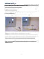
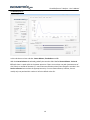
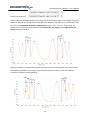
Since TL(4) - TL(3) < Tmax, the peaks/valleys to the left of 1520 nm are not included in the calculation of
second order dispersion. Also since TR(1) - TR(2) < Tmax the peaks/valleys to the right of 1615 nm are not
included in the calculation of second order dispersion. Therefore in this example only the peaks/valleys
between 1520 nm and 1615 nm are included in the dispersion calculation (9 peak/valley points).
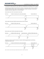
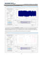
The flexibility to vary the Maximum deviation in fringe period - centre of the scan range and Maximum
deviation in fringe period - edges of the scan range allows for variation in the maximum deviation
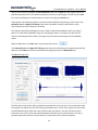
depending on where the large peak is during the sweep. For example, if the peak is near the centre of
the scan range then the period between visible points is large, as shown above. However, when the
large centre peak is located near the edges of the scan range, the period between visible points is
smaller, as shown below.
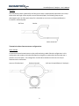
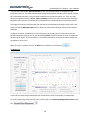
One may therefore reduce the tolerance for the Maximum deviation near the edges of the scan range in
comparison to that near the centre. The program then varies the tolerance linearly during the sweep.
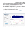
In the previous example, the error in the peak locations limited the number of useable points in the
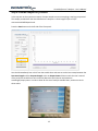
dispersion calculation to 9. The control
sets the
minimum number of peak or valley points required in order for a particular interference pattern to be
acceptable for use in the calculation of second order dispersion. The minimum number of peak/valley
points required for a measurement of second order dispersion to be possible is 5 since the large peak
and at least one peak and one valley on each side of the large peak are required. If the number of
useable points in a particular interference pattern is below the number specified in Minimum # of
peak/valley points in calculation, then that interference pattern is not used to calculate second order
dispersion and the value of Lv is incremented to see if the measurement can be made at a slightly
different wavelength. As a result, increasing this number results in higher accuracy but it leads to a
greater number of discarded points. It is important to note that the Minimum # of peak/valley points in
calculation must be less than the total number of peak/valley points in the scan range. Also note that
there are less peak/valley points when the large peak is at the centre of the scan range than when it is at
the edges of the scan range (where shorter period peaks/valleys are visible).
21