1
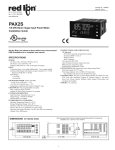
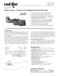
Bulletin No. PAXCDC-E
Drawing No. LP0402
Released 3/05
Tel +1 (717) 767-6511
Fax +1 (717) 764-0839
www.redlion.net
MODEL PAXCDC -SERIAL COMMUNICATIONS PLUG-IN OPTION CARDS
DESCRIPTION
This bulletin serves as a guide for the installation, configuration and
operation of the RS232 and RS485 cards for the PAX family of meters. Only
one communication card can be used at a time.
The PAX meter can be fitted with up to three different option cards. The slot
bays of the option cards are dedicated to a particular card function. The option
card functions are: serial communications, analog output and setpoint output.
Only one card from each function category can be installed into the meter.
INSTALLING AN OPTION CARD
TOP VIEW
Caution: The option and main circuit cards contain static sensitive
components. Before handling the cards, discharge static charges
from your body by touching a grounded bare metal object. Ideally,
handle the cards at a static controlled clean workstation. Also,
handle the cards by the edges only. Dirt, oil or other contaminants
that may contact the cards can adversely affect circuit operation.
Warning: Exposed line voltage exists on the circuit boards. Remove
all power to the meter AND load circuits before accessing the unit.
1. Remove the main assembly from the rear of the case. Squeeze the finger
holds on the rear cover, or use a small screwdriver to depress the side
latches to release it from the case. It is not necessary to separate the rear
cover from the main circuit card.
2. Locate the option card connector for the type of option card to be installed.
Hold the unit by the rear connector, not the display board, when installing
an option card.
3. Install the option card by aligning the option card connector with the slot
bay in the rear cover. The cards are keyed by position with different main
board connector locations. Be sure the connector is fully engaged and the
tab on the option card rests in the alignment slot on the display board.
4. Slide the assembly back into the case. Be sure the rear cover latches fully
into the case.
5. Apply the option card label to the bottom side of the meter. Do not cover
the vents on the top surface of the meter. The surface of the case must be
clean for the label to adhere properly. Apply the label to the area designated
by the large case label.
ORDERING INFORMATION
MODEL
PAXCDC
1
DESCRIPTION
PART NUMBER
RS485 Serial Communications Output Card with
Terminal Block
PAXCDC10
Extended RS485 Serial Communications Output
Card with Dual RJ11 Connector
PAXCDC1C
RS232 Serial Communications Output Card with
Terminal Block
PAXCDC20
Extended RS232 Serial Communications Output
Card with 9 Pin D Connector
PAXCDC2C
SPECIFICATIONS
PAXH Isolation For Both Cards:
Isolation To Sensor Common: 1400 Vrms for 1 min.
Working Voltage: 125 V
Isolation To User Input Common: 500 Vrms for 1 min.
Working Voltage: 50 V
RS485 Communication Card
Type: RS485 multi-point balanced interface
Isolation To Sensor & User Input Commons: 500 Vrms for 1 min.
Working Voltage: 50 V. Not Isolated from all other commons.
Baud Rate: 300 to 19.2k
Data Format: 7/8 bits; odd, even, or no parity
Bus Address: 0 to 99, max 32 meters per line
Transmit Delay: Selectable; 2 - 50 msec or 50 - 100 msec
RS232 Communication Card
Type: RS232 half duplex
Isolation To Sensor & User Input Commons: 500 Vrms for 1 min.
Working Voltage: 50 V. Not Isolated from all other commons.
Baud Rate: 300 to 19.2k
Data Format: 7/8 bits; odd, even or no parity
WIRING CONNECTIONS
RS232 Communications
RS485 Communications
The RS485 communication standard allows the connection of up to 32
devices on a single pair of wires, distances up to 4,000 ft. and data rates as high
as 10M baud (the PAX is limited to 19.2k baud). The same pair of wires is used
to both transmit and receive data. An RS485 bus is therefore always halfduplex, that is, data cannot be received and transmitted simultaneously.
RECEIVING DEVICE
PAX METER
+5V
Transmit
Enable
33K
12
Terminal Block Connection Figure
13
B(-)
A(+)
33K
14
COMM. *
15 NC
* OPTIONAL
Terminal Block Connection Figure
Extended Comms Connection Figure
RS232 is intended to allow only two devices to communicate over distances up
to 50 feet. Data Terminal Equipment (DTE) transmits data on the Transmitted
Data (TXD) line and receives data on the Received Data (RXD) line. Data
Computer Equipment (DCE) receives data on the TXD line and transmits data on
the RXD line. The PAX emulates a DTE. If the other device connected to the
meter also emulates a DTE, the TXD and RXD lines must be interchanged for
communications to take place. This is known as a null modem connection. Most
printers emulate a DCE device while most computers emulate a DTE device.
Some devices cannot accept more than two or three characters in succession
without a pause in between. In these cases, the meter employs a busy function.
As the meter begins to transmit data, the RXD line (RS232) is monitored to
determine if the receiving device is “busy”. The receiving device asserts that it
is busy by setting the RXD line into a space condition (logic 0). The meter then
suspends transmission until the RXD line is released by the receiving device.
Extended Comms Connection Figure
2
MODULE 7 - SERIAL COMMUNICATIONS PARAMETERS (!"#$%)
PARAMETER MENU
It is necessary to match the PAX meter’s serial communications parameters
to the host’s parameters before communications can be established. This is
accomplished by using the PAX front panel keys to enter (:,-8.
METER ADDRESS
%''- "
!
#
Indicates Program Mode Alternating Display.
Parameter
$%&' "
! !"##
BAUD RATE
$%&' "
! !"##
1200
2400
to
99
Enter the serial node address. With a single unit on a bus, an address is not
needed and a value of zero can be used (RS232 applications). Otherwise, with
multiple bussed units, a unique address number must be assigned to each meter.
The node address applies specifically to RS485 applications.
Selection/Value
Factory Settings are shown.
300
600
0
ABBREVIATED PRINTING
4800
9600
%$-. "
! *+,
19200
Set the baud rate to match that of other serial communications equipment.
Normally, the baud rate is set to the highest value that all of the serial
communications equipment is capable of transmitting.
YES
NO
Select abbreviated transmissions (numeric only) or full field transmission.
When the data from the meter is sent directly to a terminal for display, the extra
characters that are sent identify the nature of the meter parameter displayed. In
this case, select /0. When the data from the meter goes to a computer, it may be
desirable to suppress the node address and mnemonic when transmitting. In this
case, set this parameter to 4+5.
DATA BIT
'%)% "
!
(
7
8
PRINT OPTIONS
01) "
! /0
Select either 7 or 8 bit data word lengths. Set the word length to match that
of other serial communication equipment. Since the meter receives and
transmits 7-bit ASCII encoded data, 7 bit word length is sufficient to request
and receive data from the meter.
Odd
EVEN
NO
4+5 - Enters the sub-menu to select those meter parameters to appear in the
block print. For each parameter in the sub-menu select 4+5 for the parameter to
appear with the block print, and /0 to disable the parameter.
*Setpoints 1-4 are setpoint plug-in card dependent.
Input Value
PARITY BIT
1%- "
! 0''
YES
Max and Min Values
NO
Total Value
Setpoint values*
Set the parity bit to match that of the other serial communications equipment
used. The meter ignores the parity when receiving data, and sets the parity bit
for outgoing data. If no parity is selected with 7-bit word length the meter
transmits and receives data with 2 stop bits. (For example: 10 bit frame with
mark parity)
3
2/3
7280
)9)
53/)
4+5
4+5
4+5
4+5
/0
/0
/0
/0
Register Identification Chart
Sending Commands and Data
When sending commands to the meter, a string containing at least one
command character must be constructed. A command string consists of a
command character, a value identifier, numerical data (if writing data to the
meter) followed by a the command terminator character * or $.
Command Chart
Command Description
N
T
V
R
P
Notes
Address a specific meter. Must be followed by
one or two digit node address. Not required
when node address = 0.
Read a register from the meter. Must be
Transmit Value (read)
followed by register ID character.
Write to register of the meter. Must be
Value change (write) followed by register ID character and numeric
data.
Reset a register or output. Must be followed
Reset
by register ID character
Node Address
Specifier
Block Print Request
(read)
Initiates a block print output. Registers are
defined in programming.
Register
ID
ID
Value Description
A
Input
INP
T, P
B
Total
TOT
T, P, R
(Reset command resets total to
zero)
C
Max Input
MAX
T, P, R
(Reset command resets MAX to
current reading)
D
Min Input
MIN
T, P, R
(Reset command resets MIN to
current reading)
E
Setpoint 1
SP1
T, P, V, R
(Reset command resets the
setpoint output)
F
Setpoint 2
SP2
T, P, V, R
(Reset command resets the
setpoint output)
G
Setpoint 3
SP3
T, P, V, R
(Reset command resets the
setpoint output)
H
Setpoint 4
SP4
T, P, V, R
(Reset command resets the
setpoint output)
AOR
T, V
(Applies to manual mode)
CSR
T, V
I
J
Analog Output
Register
Control Status
Register
Applicable Commands/Comments
Command String Construction
Command String Examples:
The command string must be constructed in a specific sequence. The meter
does not respond with an error message to illegal commands. The following
procedure details construction of a command string:
1. Node address = 17, Write 350 to Setpoint 1, response delay of 2 msec min
String: N17VE350$
2. Node address = 5, Read Input value, response delay of 50 msec min
String: N5TA*
1. The first 2 or 3 characters consist of the Node Address Specifier (N) followed
by a 1 or 2 character node address number. The node address number of the
meter is programmable. If the node address is 0, this command and the node
address itself may be omitted. This is the only command that may be used in
conjunction with other commands.
2. After the optional address specifier, the next character is the command
character.
3. The next character is the register ID. This identifies the register that the
command affects. The P command does not require a register ID character.
It prints according to the selections made in print options.
4. If constructing a value change command (writing data), the numeric data is
sent next.
5. All command strings must be terminated with the string termination
characters * or $. The meter does not begin processing the command string
until this character is received. See timing diagram figure for differences of
* and $ terminating characters.
3. Node address = 0, Reset Setpoint 4 output, response delay of 50 msec min
String: RH*
Sending Numeric Data
Numeric data sent to the meter must be limited to 5 digits (-19,999 to
99,999). If more than 5 digits are sent, the meter accepts the last 5. Leading
zeros are ignored. Negative numbers must have a minus sign. The meter ignores
any decimal point and conforms the number to the scaled resolution. (For
example: the meter’s scaled decimal point position = 0.0 and 25 is written to a
register. The value of the register is now 2.5 In this case, write a value = 25.0).
Note: Since the meter does not issue a reply to value change commands, follow
with a transmit value command for readback verification.
The end of the response string is terminated with a carriage return <CR> and
<LF>. When block print is finished, an extra <SP><CR> <LF> is used to
provide separation between the blocks.
Receiving Data
Data is transmitted by the meter in response to either a transmit command
(T), a print block command (P) or User Function print request. The response
from the meter is either a full field transmission or an abbreviated transmission.
In this case, the response contains only the numeric field. The meter response
mode is established in programming.
Abbreviated Transmission
Byte
Description
Byte
Description
13
12 byte data field, 10 bytes for number, one byte for sign,
one byte for decimal point
<CR> carriage return
1, 2
2 byte Node Address field [00-99]
14
<LF> line feed
<SP> (Space)
15
<SP>* (Space)
4-6
3 byte Register Mnemonic field
16
<CR>* carriage return
17
<LF>* line feed
7-18
12 byte data field; 10 bytes for number, one byte for sign, one byte for
decimal point (The T command may be a different byte length)
1-12
Full Field Transmission
3
* These characters only appear in the last line of a block print.
19
<CR> carriage return
20
<LF> line feed
21
<SP>* (Space)
22
<CR>* carriage return
Meter Response Examples:
23
<LF>* line feed
1. Node address = 17, full field response, Input = 875
17 INP
875 <CR><LF>
The abbreviated response suppresses the node address and register ID,
leaving only the numeric part of the response.
* These characters only appear in the last line of a block print.
The first two characters transmitted are the node address, unless the node
address assigned =0, in which case spaces are substituted. A space follows the
node address field. The next three characters are the register ID (Serial
Mnemonic).
The numeric data is transmitted next. The numeric field is 12 characters long
(to accommodate the 10 digit totalizer), with the decimal point position floating
within the data field. Negative value have a leading minus sign. The data field
is right justified with leading spaces.
2. Node address = 0, full field response, Setpoint 2 = -250.5
SP2
-250.5<CR><LF>
3. Node address = 0, abbreviated response, Setpoint 2 = 250, last line of block
print
250<CR><LF><SP><CR><LF>
4
SERIAL COMMANDS FOR PAX SOFTWARE
(CSR) Control Status Register
Examples:
The Control Status Register is used to both directly control the meter’s
outputs (setpoints and analog output), and interrogate the state of the setpoint
outputs. The register is bit mapped with each bit position within the register
assigned to a particular control function. The control function are invoked by
writing to each bit position. The bit position definitions are:
1. Set manual mode, turn all setpoints off:
7 6 5 4 3 2 1 0:bit location
VJ<30>* or VJ0*
ASCII 0 = 0 0 1 1 0 0 0 0 or <30>
V is command write, J is CSR and * is terminator.
bit 0: Setpoint 1 Output Status
0 = output off
1 = output on
bit 1: Setpoint 2 Output Status
0 = output off
1 = output on
bit 2: Setpoint 3 Output Status
0 = output off
1 = output on
bit 3: Setpoint 4 Output Status
0 = output off
1 = output on
bit 4: Manual Mode
0 = automatic mode
1 = manual mode
bit 5: Always stays 0, even if 1 is sent.
bit 6: Sensor Status (PAXT only)
0 = sensor normal
1 = sensor fail
bit 7: Always stays 0, even if 1 is sent.
2. Turn SP1, SP3 outputs on and SP2, SP4 outputs off:
7 6 5 4 3 2 1 0:bit location
VJ<35>* or VJ5*
ASCII 5 = 0 0 1 1 0 1 0 1 or <35>
3. Select Automatic mode:
7 6 5 4 3 2 1 0:bit location
VJ<40>* or VJ@*
ASCII @ = 0 1 0 0 0 0 0 0 or <40>
Note: Avoid writing values <0A> (LF), <0D> (CR), <24> ($) and <2E> (*)
to the CSR. These values are interpreted by the meter as end of command
control codes and will prematurely end the write operation.
(AOR) Analog Output Register
The Analog Output Register controls the analog output of the meter. The
manual mode must first be engaged by setting bit 4 of the Control Status
Register. The range of values of this register is 0 to 4095, which corresponds to
0 mA, 0 V and 20 mA, 10 V; respectively. The table lists correspondence of the
output signal with the register value.
Register Value
Although the register is bit mapped starting with bit 7, HEX < > characters
are sent in the command string. Bits 7 and 5 always stay a zero, even if a “1” is
sent. This allows ASCII characters to be used with terminals that may not have
extended character capabilities.
Writing a “1” to bit 4 of CSR selects manual mode. In this mode, the setpoint
outputs are defined by the values written to the bits b0, b1, b2, b3; and the
analog output is defined by the value written to the AOR. Internal control of
these outputs is then overridden.
In automatic mode, the setpoint outputs can only be reset off. Writing to the
setpoint output bits of the CSR has the same effect as a Reset command (R).
The contents of the CSR may be read to interrogate the state of the setpoint
outputs and to check the status of the temperature sensor (PAXT only).
Output Signal*
I (mA)
V (V)
0
0.000
0.000
1
0.005
0.0025
2047
10.000
5.000
4094
19.995
9.9975
4095
20.000
10.000
*Due to the absolute accuracy
rating and resolution of the output
card, the actual output signal may
differ 0.15% FS from the table
values. The output signal
corresponds to the range selected
(20 mA or 10 V).
Writing to this register while the meter is in the manual mode causes the
output signal to update immediately. While in the automatic mode, this register
may be written to, but the output will not update until the meter is placed in
manual mode.
Examples:
1. Set output to full scale:
VI4095*
2. Set output to zero scale:
VI0*
At the start of the time interval t1, the computer program prints or writes the
string to the com port, thus initiating a transmission. During t1, the command
characters are under transmission and at the end of this period, the command
terminating character (*) is received by the meter. The time duration of t1 is
dependent on the number of characters and baud rate of the channel.
Command Response Time
The meter can only receive data or transmit data at any one time (half-duplex
operation). The meter ignores commands while transmitting data, but instead
uses RXD as a busy signal. When sending commands and data to the meter, a
delay must be imposed before sending another command. This allows enough
time for the meter to process the command and prepare for the next command.
t1 = (10 * # of characters) / baud rate
At the start of time interval t2, the meter starts the interpretation of the
command and when complete, performs the command function. This time
interval t2 varies from 2 msec to 50 msec. If no response from the meter is
expected, the meter is ready to accept another command.
If the meter is to reply with data, the time interval t2 is controlled by the use
of the command terminating character. The standard command line terminating
character is ‘*’. This terminating character results in a response time window of
50 msec minimum and 100 msec maximum. This allows sufficient time for the
release of the sending driver on the RS485 bus. Terminating the command line
with ‘$’ results in a response time window (t2) of 2 msec minimum and 50 msec
maximum. The faster response time of this terminating character requires that
sending drivers release within 2 msec after the terminating character is received.
At the beginning of time interval t3, the meter responds with the first
character of the reply. As with t1, the time duration of t3 is dependent on the
number of characters and baud rate of the channel. t3 = (10 * # of characters) /
baud rate. At the end of t3, the meter is ready to receive the next command.
The maximum serial throughput of the meter is limited to the sum of the
times t1, t2 and t3.
Timing Diagram Figure
5
Communication Format
Data is transferred from the meter through a serial communication channel.
In serial communications, the voltage is switched between a high and low level
at a predetermined rate (baud rate) using ASCII encoding. The receiving device
reads the voltage levels at the same intervals and then translates the switched
levels back to a character.
The voltage level conventions depend on the interface standard. The table
lists the voltage levels for each standard.
LOGIC
INTERFACE STATE
RS232*
RS485*
1
mark (idle)
TXD,RXD; -3 to -15 V
a-b < -200 mV
0
space (active)
TXD,RXD; +3 to +15 V
a-b > +200 mV
Character Frame Figure
* Voltage levels at the Receiver
Data is transmitted one byte at a time with a variable idle period between
characters (0 to ∞). Each ASCII character is “framed” with a beginning start bit,
an optional error detection parity bit and one or more ending stop bits. The data
format and baud rate must match that of other equipment in order for
communication to take place. The figures list the data formats employed by
the meter.
Parity bit
After the data bits, the parity bit is sent. The transmitter sets the parity bit to
a zero or a one, so that the total number of ones contained in the transmission
(including the parity bit) is either even or odd. This bit is used by the receiver
to detect errors that may occur to an odd number of bits in the transmission.
However, a single parity bit cannot detect errors that may occur to an even
number of bits. Given this limitation, the parity bit is often ignored by the
receiving device. The PAX meter ignores the parity bit of incoming data and
sets the parity bit to odd, even or none (mark parity) for outgoing data.
Start bit and Data bits
Data transmission always begins with the start bit. The start bit signals the
receiving device to prepare for reception of data. One bit period later, the least
significant bit of the ASCII encoded character is transmitted, followed by the
remaining data bits. The receiving device then reads each bit position as they
are transmitted. Since the sending and receiving devices operate at the same
transmission speed (baud rate), the data is read without timing errors.
Stop bit
The last character transmitted is the stop bit. The stop bit provides a single
bit period pause to allow the receiver to prepare to re-synchronize to the start of
a new transmission (start bit of next byte). The receiver then continuously looks
for the occurrence of the start bit.
6
This page intentionally left blank
7
LIMITED WARRANTY
The Company warrants the products it manufactures against defects in materials and workmanship
for a period limited to one year from the date of shipment, provided the products have been stored,
handled, installed, and used under proper conditions. The Company’s liability under this limited
warranty shall extend only to the repair or replacement of a defective product, at The Company’s
option. The Company disclaims all liability for any affirmation, promise or representation with
respect to the products.
The customer agrees to hold Red Lion Controls harmless from, defend, and indemnify RLC against
damages, claims, and expenses arising out of subsequent sales of RLC products or products
containing components manufactured by RLC and based upon personal injuries, deaths, property
damage, lost profits, and other matters which Buyer, its employees, or sub-contractors are or may be
to any extent liable, including without limitation penalties imposed by the Consumer Product Safety
Act (P.L. 92-573) and liability imposed upon any person pursuant to the Magnuson-Moss Warranty
Act (P.L. 93-637), as now in effect or as amended hereafter.
No warranties expressed or implied are created with respect to The Company’s products except those
expressly contained herein. The Customer acknowledges the disclaimers and limitations contained
herein and relies on no other warranties or affirmations.
Red Lion Controls AP
Red Lion Controls
20 Willow Springs Circle
Red Lion Controls BV
Basicweg 11b
31, Kaki Bukit Road 3,
#06-04/05 TechLink
York PA 17402
NL - 3821 BR Amersfoort
Singapore 417818
Tel +1 (717) 767-6511
Tel +31 (0) 334 723 225
Tel +65 6744-6613
Fax +1 (717) 764-0839
Fax +31 (0) 334 893 793
Fax +65 6743-3360