1
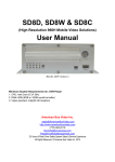
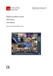
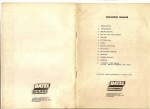
Digital Video Recorder DMR2008 1 Classification Description This equipment is designed to provide reasonable protection against Class A harmful interference when the equipment is operated in a commercial Digital Device environment. If the device is purchased or sold for any other use, please replace it with the one appropriate for the residential area. [Class A: Device for Commercial Use.] FCC Compliance Statement Caution : Any changes or modification in construction of this device which are not expressly approved by the party responsible for compliance could void the user’s authority to operate the equipment. Note : This equipment has been tested and found to comply with the limits for Class A digital device, pursuant to part 15 of the FCC Rules. These limits are designed to provide reasonable protection against harmful interference when the equipment is operated in a commercial environment. This equipment generates, uses, and can radiate radio frequency energy and, if not installed and used in accordance with the instruction manual, may cause harmful interference to radio communications. Operation of this equipment in a residential area is likely to cause harmful interference in which case the user will be required to correct the interference at his own expense. User’s Manual The description written in the manual may not be exactly the same because the device may be updated. Thank you for purchasing DMR2008. Please read this manual before using the device and keep it safely for your reference in the future. The appearance and the functionalities of the product as described in this manual can be changed in the future without advance notice. * This device does not guarantee immediate storage of data when problem occurs. The manufacturer does not that responsibility for loss or damage of data. It is left to the user’s discretion for safe maintenance of data. Warning: The cautions mentioned in this manual described important safety related subjects and must be observed at all times. Please confirm the following matters before installing or using the product. General Cautions: 1. Only the power supply adapter included in the product or otherwise approved by the manufacturer must be used. 2. Do not arbitrarily disassemble or modify the product 2 3. The product must be repaired at the place of purchase or approved A/S center 4. Do not place any container with liquid near or on top of the product. (If liquid comes into contact with the product and causes system malfunction, stop and turn off the product and call the place of purchase.) 5. Do not operate the product with wet hands. 6. Only trained technicians must install, move or reinstall the product. 7. The Product must be put to earth. 8. The grounding conductor may not be connected to the gas pipe, water pipe, or telephone line. 9. Metal objects must not be put into the product. 10. Do not spray the insecticide or flammable spray. 11. When cleaning the external body, do not spray water, thinner or organic solvent. 12. If burning odor or strange noise is detected, stop and turn off the product, and call the place of purchase. 13. Do not insert foreign substances into the ventilation outlet on the side. 14. Do not drop or apply the strong vibration or shock to the product. 15. Be careful not to clog the ventilation inlet at the bottom or outlet on the side. 16. Do not touch the product when there is lightening. 17. Do not install the product near heat generating devices such as a heater. 18. Do not install the product on an inclined, uneven, or vibrating area. 19. Always use the grounded adapter for the power supply. 20. Do not connect in the middle of the power source cord or use the cord extension. 21. Do not touch the power cord with wet hands. 22. Do not wet the power cord. 23. When pulling out the power plug, hold the main body of the adapter. 24. Periodically inspect the power plug.. 25. When not using the product for a prolonged period of time, pull the power cord off the outlet. 26. Do not turn off the product by pulling out the power adapter. Use the power on/off switch on the front panel to properly stop the operation. If the power on/off switch does not immediately act after abnormal interruption of system, push down the switch and hold it for at least 4 seconds. 27. Do not turn off, vibrate or shock the system while the hard disk is in operation. 28. Use the same or manufacturer’s suggested product for the remote controller batteries. When replacing the batteries, make sure the poles of the batteries are properly placed. 29. The replaced batteries should be disposed as recommended by the manufacturer. 3 --CONTENTS— 1. INTRODUCTION 2. SYSTEM ORGANIZATION A. PARTS B. FRONT SECTION C. REAR SECTION D. INTERNAL STRUCTURE E. HDD INSTALLATION 3. INSTALLATION (CAMERA & MONITOR) 4. NETWORK CONNECTION 5. CONNECTING TO PC 6. REMOTE MONITORING 7. DVR108NSB MANAGEMENT 8. BASIC CONFIGURATION 9-1. RECORDING MODE [RECORDING CONFIGIRATION] A. PICTURE CONTROL B. CONFIGURATION 9-2. DISK STATUS [HDD DISK INFORMATION] 9-3. MOTION DETECTION A. DETECTED AREA EDITING B. SENSITIVITY 9-4. NETWORK CONFIGURATION A. MANUAL IP CONFIGURATION B. PPPoE IP CONFIGURATION 9-5. CHANNEL SWITCH SEQUENCE 9-6. UTILITY A. DISK TEST [HDD DISK TEST] B. DISK INITIALIZE C. FACTORY SETTING D. PASSWORD CHANGE E. CLOCK SETTING F. REMOTE CONTROLLER CONFIGURATION G. FIRMWARE UPDATE 9-7. PRODUCT INFORMATION [VERSION INFORMATION] 4 10. REPLAYING THE RECORDED IMAGE A. REPLAY CHANNEL SELECTION MENU B. REPLAY TIME SELECTION MENU C. REPLAY DISPLAY 11. SPECIFICATION 12. SERVICE AND SUPPORT 1. DVR108NSB Introduction DMR2004 (Digital Video Recorder) is the system consisting of a group of the cameras installed in the areas that require security to monitor, record and then search by time, day, camera and event. The digital system enables monitoring, searching, backup and controlling of camera from a long distance beyond what was ever possible with the existing analog CCTV system. WARNING: NETWORK FUNCTION CAN BE ADDED OR NOT DEPENDS ON THE MODEL OF PRODUCTS. Main Applications Kindergarten / School / Private Institute / Library / Office Factory / Warehouse / Parking Lot Convenient Store / Pharmacy / Internet Café Apartments / Playground Other areas that require security Main Features The stand-alone, non-pc type DMR2008 can provide all system function. Real-time monitoring and recording of up to 8 cameras are possible at the same time. (Real-time monitoring – 240 FPS / recording – 30 FPS) Motion can be automatically recorded through motion detection function. Automatic error correction during operation is provided through watch dog function. Remote access and monitoring is enable with the network plug & play. (Support for dynamic IP and virtual IP.) Easy and convenient button and remote controller operation. Network Support 1. Easy access through user id and password. 2. Remote monitoring using Internet Explorer (DMR2008 Explorer). 3. Thorough monitoring using the dedicated program (DMR2008 Manager). 4. Remote access using the network plug & play with no setup (Support for dynamic IP and virtual IP). 5. Support for mobile access using PDA (DMR2008 Mobile Manager). 6. Transmission of the emergency situation and screen through SMS 5 2. SYSTEM ORGANIZATION A. PARTS DMR2008, Remote controller (including 2 AAA batteries), adaptor, power plug, User’s Guide, ‘CCTV in Operation’ Warning Sticker (Large and small each) B. Front Section The front section of DMR2008 consists of the LED part which can display current system conditions and the key operation part which can operate the HDD Rack and DMR2008. The DMR2008 function keys can be divided into DM R2008 panel section and DMR2008 remote controller section. The DMR2008 panel provides the equivalent functionalities as the remote controller as shown below. ` [ ][QUAD] Shows all eight images of the cameras on one screen. [X] [PLAY] Shows the recorded image for each channel. [] [MENU] Shows the menu to set up DMR2008 functions. [■] [ESC] Cancels the current condition or moves up a level. [i][UP],[j][DOWN], Changes the selected item of the selected item [h][LEFT],[g][RIGHT] [●][ENTER] Selects or executes the selected item [F1],[F2],[F3],[F4],[F5] Designates the specific D M R 2 0 0 8 when controlling multiple DMR2008’s with one remote controller. 6 C. Rear Section The rear section of DMR2008 consists of BNC Connector Input, 8ch Camera Input, TV-Out 2ch. In addition, there is LAN port, power plug and power switch. (WARNING: NETWORK FUNCTION CAN BE ADDED OR NOT DEPEND ON THE MODEL OF PRODUCTS.) D. Internal Structure Internally, DVR108 consists of the main board which processes the images, HDD which stores data, Key Pad which provides the functional keys, and the power supply section. 7 E. Installing the HDD The system can use any LBA mode supporting hard disks with ATA-3 or higher. (Version 22 or lower only supported up to 120 GB.) If the hard disk is not installed or connected for some problem at the initial power on, the system tries to connect the hard disk for 10 seconds and then operates without it. For this case, the message ‘DISK FAIL’ flashes on the monitor, but the system normally operates except for recording. The hard disk is formatted not all at once, but as needed as recording continues. Once the hard disk is completely formatted, then no more formatting is performed. 1. Installation HDD disk must be setup as the master. If it is set as other than the master mode, DISK FAIL message is output, and no recording is done. [EX. SEAGATE 7200RPM product] 2. Assemble the HDD disk to the HDD rack. Connect IDE cable to DMR2008. Installation is completed by locking the rack with the rack key. (To prevent loss or damage, locking with the key is necessary.) 8 3. Installation (Camera & Monitor) Input Port (CH1 CH2 CH3 CH4 CH5 CH6 CH7 CH8) Each of 8 channels is connected to the camera image terminal. Output Port (TV-OUT) Two output ports enable additional DVR108 image output. LAN [Network Connection) This is the terminal for Internet connection to provide remote monitoring of the recorded and real-time images. Power Supply Input Only an adaptor connection can be used. (Warning, no use of other types of adaptor) Main Power Switch It’s a main power switch which controls the power. [Power of on/off does not work when the remote controller is off.] Attention When the power of DVR2008 is abruptly cut off, it can cause malfunction of HDD and/or DMR2008 Always use the power switch of DMR2008 rear side or on the remote controller. 9 4. Network Connection DMR2008 must be connected to the network first in order to monitor, record, search recorded images, change the parameter setting and control the camera (PAN/TILT), etc. remotely. The following procedure describes network c onnection. DMR2008 supports fixed and dynamic IP as well as PPPoE (ADSL connection). You can select the most appropriate connection for your situation. Section 8-4 of this manual describes the parameter setting in details. 1. Internet Line Connection a. Fixed IP Connection Set the Manual IP Configure parameters and then connect the cable. b. Dynamic IP Connection Set the Automatic IP Configure parameters and then connect the cable. If there is the firewall, open TCP 913, 914 and 915 ports. 2. ADSL Modem Connection a. Fixed IP Connection Set the Manual IP Configure parameters and then connect the cable. b. Dynamic IP Connection Set the Automatic IP Configure parameters and then connect the cable. c. PPPoE Validated Connection ADSL connection to Internet is done through user validation using the user ID and password. DMR2008 can be directly connected to Internet via ADSL modem. Set the PPPoE IP Configure parameters and connect the cable. Depending on the type of the modem, DMR2008 may not be directly connected to the ADSL modem. In that case, the broadband router (additional purchase) may be needed between the model and DMR2008 for network connection. ADSL modem of ISP is using the cable modem requires checking of Mac address. In that case, the broadband router is needed for network connection, and Mac address must be configured. 3. Cable Modem Connection a. Fixed IP Connection Set the Manual IP Configure parameters and then connect the cable. b. Dynamic IP Connection Set the Automatic IP Configure parameters and then connect the cable. A. Depending on the type of the modem, DMR2008 may not be directly connected to the cable modem. In that case, the broadband router (additional purchase) may be needed between the model and DMR2008 for network connection. B. Some ISP’s using the cable modem requires checking of Mac address. In that case, the broadband router is needed for network connection, and Mac address must be configured. 10 * Advantech does not assume any responsibility for the problem due to Mac address copy. 4. DMR2008 Connection to PC - DMR2008 SERVER MODE: When DMR2008 is connected to server [However, when IP router is being used, fixed IP should be used and TCP (913,914,915) port should be opened] a. DMR2008 client mode : a multiple of DMR2008 can be connected to one IP router. However, TCP (913, 914, 915) port should be opened when IP router is being used. b. DVR2008 server mode : only one DMR2008 can be connected to one IP router. However, when DMR2008 is connected to IP router, TCP (913, 914, 915) port should be opened. 5. DVR2008 Connection to PC DVR108 can be directly connected to PC. (This connection requires DMR2008 Manager.) 1. Direct Connection of DMR2008 to PC a. Crossed UTP cable is required. PC and DMR2008 must be configured for automatic IP setting. b. Execute DMR2008 Manager, the dedicated connection program. Configure Connect to Direct (Auto IP) and click SCAN. 2. Connection of DMR2008 and PC to the Internal Network using HUB a. Both DMR2008 and PC must be connected to HUB. DMR2008 must be configured for Auto IP. b. Execute DMR2008 Manager, the dedicated connection program. Configure Connect to Direct (Auto IP) and click SCAN. 6. Remote Monitoring Remote monitoring of the DMR2008 images is available through DMR2008 Explorer via Internet Explorer or DMR2008 Manager. (Please refer to the S/W manual for detailed description.) To view the image, the user must log in to www.adamsecu.com as a member and enter Mac Address of DMR2008 and 11 H/W address for the service. A. DVR108 Explorer A. Log in www.adamsecu.com and join the site as the member. Log in again after entering Mac address. B. The image will appear on the screen through DMR2008 Explorer by clicking Service. B. DMR2008 Manager Log in www.adamsecu.com as a member using the user ID and password. 1. Select the available DMR2008. 2. Select the channel. 12 7. DMR2008 Operation The main display can show one channel, four channels, six channels, seven channels, and eight channels. indicates on the left upper corner, and it keeps When multiple channels are being recorded, showing the signal for one second when the record is done. 13 By default, the monitor shows Quad ch1 → ch2 → ch3 → ch4 → ch5 → ch6 → ch7 → ch8 → Quad→ 6 Channel → 7 Channel → 8 Channel. The display is automatically switched, but the user can configure the display switch speed and channels using CHANNEL SWITHCH SEQUENCE. The automatic display switch can be changed to manual by pressing [UP] or [DOWN] keys. Pressing [UP] key, the display changes Quad -> ch1 -> ch2 -> ch3 -> ch4 -> ch5 -> ch6 -> ch7 -> ch8 -> Quad -> ch6 -> channel 7 -> channel 8 and back to Quad while pressing [DOWN] changes the displays in the opposite way. Pressing [ENTER] changes the display switch to the automatic mode. 8. DVR108 Basic Configuration The main menu can be activated by pressing [MENU] button on the front section of DMR2008. (It is equivalent to [MENU] key on the remote controller.) Pressing [MENU] while at the Channel Monitor mode displays the following configuration menu. - RECORD MODE - DISK STATUS - MOTION DETECTION - NETWORK CONFIGURATION 14 - CHANNEL SWITCH SEQUENCE - UTILITY - PRODUCT INFORMATION Use [UP] or [DOWN] key to move among the menu items. Press [ENTER] or [MENU] to select the item to configure. 9.1 Recoding Mode In this mode, DMR2008 recording mode, recording frame, brightness and color tones can be changes. CONFIGURATION: controls the picture of the recorded image on the screen. [Continuous recording and motion recording configuration] -SETTING / EXIT: To maintain the configured values, the mode must go back to main menu by pressing [ENTER] or [MENU]. A. Picture Control: The record or current image on the screen for the selected channel can be modified - BRIGHTNESS: This parameter configures the brightness of the image. - CONTRAST: This parameter configures the brightness/darkness contrast of the image. - CHROMA SATURATION: This parameter can change and set the color distinctness. - CHROMA GAIN: This parameter configures the chroma gain. - HUE: This parameter configures the color tone. changed to factory configured initial values. 15 DEFAULT SET: All parameters can be - SETTING / EXIT: To maintain the current values, the mode must go back to RECORDING MODE by pressing [ENTER] or [MENU]. B. CONFIGURATION This item is selected for continuous recording. There is a submenu. DMR2008 is only configured for Motion Detection as a factory default. The continuous recording can be configured by setting the frames for the item that has FRAME OFF for the continuous recording. (As the values of resolution and frame increase, total recording time will decrease.) - COMPRESSION RATE : This determines the Wavelet compression rate. The quality of the screen goes up as the rate is decreased. - SHARPNESS: This determines the sharpness of the screen. The lower value indicated sharper image – NORMAL RECORDING FRAME RATE : This determines the number of frames per second for continuous recording. 30, 15, 10, 8, 6, 5, 4, 3, 2 or 1 frame per second is possible. For long term recording, 2, 3, 4, 5, 6, 7, 8, 9 or 10 seconds per frame can also be selected. When setting for the continuous recording, this value should be same as EVENT RECORDING FRAME RATE. (Note: If this value is not set, there will be no recording.) There will be no recording if EVENT RECORDING FRAME RATE is OFF even during continuous recording. Set it at the same FRAME RATE. EVENT RECORDING FRAME RATE: This determines the number of frames per second for movement detected recording. 30, 15, 10, 8, 6, 5, 4, 3, 2 or 1 frame per second is possible. For long term recording, 2, 3, 4, 5, 6, 7, 8, 9 or 10 seconds per frame can also be selected. Set it to OFF when there is no continuous recording in the same channel. 16 (Note: If this value is not set, there will be no recording.) - EVENT HOLD TIME (SEC) : This sets the duration of continuous recording after movement is detected. The value can be change from 0 to 255 by the [LEFT] and [RIGHT] keys. - [CH1],[CH2],[CH3],[CH4] NOLMAL RECORDING , [CH1],[CH2],[CH3],[CH4] EVENT RECORDING PREVIEW : The screen quality with the configured parameters can be previewed. Using the DMR2008 memory, recording and replaying can be repeated. The currently available memory and recorded memory are displayed in the bar graph on the screen. When the memory is full with the recorded images, it is automatically changed to replay. Pressing [ENTER] during recording changes the mode to replay. Pressing [ESC] changes to NORMAL RECORDING. (Please note that, since it is the average time, the recording period may not be exact.) [CH1],[CH2],[CH3],[CH4],[CH5],[CH6],[CH7],[CH8] NORMAL RECORDING, [CH1],[CH2],[CH3],[CH4], [CH5], [CH6], [CH7], [CH8] EVENT RECORDING mode can preview in each recording mode. - SETTING / EXIT : To maintain the current values, the mode must go back to NORMAL RECODING by pressing [ENTER] or [MENU]. 9-2. Disk Status [HDD Information] The type of hard disk, and used space and recorded time for each channel can be reviewed. Hard disk storage method can be configured. 17 - Model name of the hard disk: DMR2008 can automatically recognize the hard disk. The recognized hard disk model and the total storage capacity can be checked with the actual information. - Display of the record image for each channel in HOUR / MINUTE / SECOND: This time is calculated by the configured FRAME RATE parameter. For example, if the FRAME RATE is 30 FPS, then 30 frames are calculated as 1 second. For 10 seconds per frame, 1 frame is calculated as 10 seconds. - ENDLESS RECORDING: When there is no more hard disk left, the oldest images are overwritten with the latest ones. - FULL CAPACITY RECORDING: Recording is stopped and “DISK FULL” is displayed on the screen. In this case, every other functions but recording is operated normally. However, when full capacity recording is on and if there is no space available in HDD, image can not be transferred via Internet. - SETTING / EXIT: To maintain the current values, the [ENTER] or [MENU] key must be pressed. 9-3 Motion Detection If the Recording Mode is set as Event Recording, then Motion Detection ON/OFF as well as Detected Area Editing and Sensitivity can be configured. - CH1, Ch2, Ch3, CH4, CH5, CH6, CH7, CH 8: When one of the eight channels can be selected with the [ENTER] or [MENU] keys, the selected channel and its motion detection range appears on the screen. (The motion detected range is marked with green color.) - Detection: Motion detection of the selected channel can be turned ON or OFF. What is displayed is the opposite of the current setting. i.e. If the current setting is Motion Detection ON, then OFF is displayed. If OFF is selected, the Motion Detected range disappears. 18 A. Detected Area Editing - Motion Detection Area: The range can be set up in details. Up to 16 squares horizontally and 12 squares vertically (total of 192 grids) can be set up. Current square is displayed in orange while the selected detection area is displayed in green. - [LEFT], [RIGHT], [UP] and [DOWN]: These keys move the cursor location. When the cursor reaches the end, then it moves backward. - [ENTER]: It turns on or off motion detections at the current cursor position. If current mode is ON, then it changes to OFF and vice versa. The green display disappears when it is turned OFF. - [PLAY]: It changes the Motion Detection range to the default. The default sets all squares except the edge to ON. In other words, Motion Detection range is 14 x 10. - [ESC]: It cancels new setting, loads the old setting and moves back to MOTION DETECTION. - [MENU]: The new setting is stored and moves back to MOTION DETECTION. B. Sensitivity It changes sensitivity of Motion Detection and has the following submenu. - THRESHOLD: This determines brightness differenced of the detected object. A value between 15 and 115 is valid. As the value gets lower, sensitivity increases. (15: maximum sensitivity, 115; minimum sensitivity) - VELOCITY: This determines speed of detected object. A value between 10 and 60 is valid. As the value gets lower, the speed increases. (10: maximum speed, 60: minimum speed) - DETECTION BLOCK COUNT: This determines the number of grids out of 192 (16X12) that need to be detected at the same time. A value between 148 is valid. 19 1 means that detection is valid if at one grid shows detection while 48 means at least 48 grids must show detection to be valid. (1: minimum range, 48: maximum range) If the valid motion detection occurs, ‘MOTION DETECTION’ message along the detected area are flashed on the screen for immediate indication. -[ESC]: The changed setting is canceled, the old setting is recalled, and the mode is changed back to MOTION DETECTION. -[ENTER] or [MENU]: The changed setting is saved, and the mode is changed back to MOTION DETECTION. SETTING / EXIT: To maintain the current values, the [ENTER] or [MENU] key must be pressed. Canceling by pressing [ESC] in this mode changes the new configuration of DETECTION ON/OFF to the old values. But the saved DETECTED AREA EDITING and SENSITIVITY values are not changed. 9-4. Network Configuration This enables monitoring of recorded and current image remotely by connecting DMR2008 to the network. It shows the Internet registration parameters which can be modified in accordance with the current user network environment. [Support for fixed IP, dynamic IP, PPPoE, virtual IP (private IP)]. - IP: This is the address of DMR2008 on the network. - GATEWAY IP: In general, this is the router address. - Subnet Mask: This is the address that logically partitions the network. - DNS: This is the address of the system that manages the domain names. - HOST IP: This is the IP address of the DMR2008 service server. - MAC Address: This is the hardware address of DMR2008. - AUTOMATE IP CONFIGURE / MANUAL IP CONFIGURE / PPPoE IP CONFIGURE Automatic IP CONFIGURE: This is selected when the user network supports dynamic IP (DHCP). (The address is automatically assigned.) MANUAL IP CONFIGURE: This is selected when the user network is set up for the fixed IP. 20 PPPoE IP CONFIGURE: This is selected when the user network requires ADSL user validation. - DCP IN KOREA / DCP IN USA / MANUAL SETTING HOST IP / DMR2008 SERVER MODE : DCP IN KOREA : connect to Korean server [automatically configured] DCP IN USA : connect to U.S.A. server [automatically configured] MANUAL SETTING HOST IP : When remote PC is using private IP (Only Viewer) - DVR2008 SERVER MODE : When DMR2008 is used as server. [IP should be based on private IP, TCP (913,914,915) PORT should be opened] a. DMR2008 client mode : a multiple of DMR2008 can be connected to one IP router. However, TCP (913,914,915) PORT of remote site should be opened. b. DMR2008 server mode : a DMR2008 is connected to one IP router, however, TCP (913,914,915) PORT should be opened - REMOTE CONFIGURE : DMR2008 setting configuration via network. a. Disable : DMR2008 configuration can not be changed from the remote site. b. Enable : DMR2008 configuration can be changed from the remote site. - SETTING / EXIT : To maintain the current values, the [ENTER] or [MENU] key must be pressed. A. MANUAL IP CONFIGURATION This is selected when the user network is set up for the fixed IP. This is the method of manually entering the IP address from ISP or the network manager for the network connection. The addresses for IP, GATEWAY IP, SUBNET MASK and DNS must be specified. The numbers can be entered only 21 form the numeric keys on the remote controller. - SETTING / EXIT: To maintain the current values, the [ENTER] or [MENU] key must be pressed. Enter User ID and password. For entering the user ID and password, the keys on the remote controller must be used. The numeric keys of the remote controller can also enter the alphabetic letters as follows: (1) Æ [1], [.], [Q], [Z] (2) Æ [2], [A], [B], [C] (3) Æ [3], [D], [E], [F] (4) Æ [4], [G], [H], [I] (5) Æ [5], [J], [K], [L] (6) Æ [6], [M], [N], [O] (7) Æ [7], [P], [R], [S] (8) Æ [8], [T], [U], [V] (9) Æ [9], [W], [X], [Y] (QUAD) Æ [‘], [/], [!] (0) Æ [0], [_], [?], [%] (10) Æ [()], []], [+] For example, to enter ‘ADVENTECH’, (2) (2) (3) (3) (8) (8) (8) (8) (2) (2) (6) (6) (6) (8) (8) (3) (3) (3) (2) (2) (2) (2) (4) (4) (4) (4). - SETTING / EXIT: To maintain the current values, the [ENTER] or [MENU] key must be pressed. 22 9-5. Channel Switch Sequence The switching sequence and the interval time of QUAD and 8 channels can be configured while monitoring the DMR200 8screen. CH1, CH2, CH3, CH4, CH5, CH6, CH7, CH8, CH1-2-3-4-5-6, CH1-2-3-4-5-6-7, CH1-2-3-4-5-6-7-8 : Each display can be turned ON or OFF by selecting each item and then pressing the [ENTER] or [MENU] key. - INTERVAL TIME: This determines the interval time for each display. Using the [MENU] key, the values can range from 1 second to 12 seconds. The value can only be incremented. After 12, the value changes back to 1. - SETTING / EXIT: To maintain the current values, the [ENTER] or [MENU] key must be pressed. 9-6. UTILITY 23 - UTILITY: In this menu, the installed disk can be initialized; the recorded image can be deleted; the parameters can be reset to the factory default values; the pass word can be changed; accurate time can be set; and the remote controller channels can be changed. DISK TEST DISK INITIALIZE FACTORY SETTING PASSWORD CHANGE CLOCK SETTING REMOTE CONTROLLER - Exit: To maintain the current values, the [ENTER] or [MENU] key must be pressed. A. DISK TEST [HDD DISK TEST] - DISK TEST: It checks for the corrupted files and recovers them. It automatically finds the errors and corrects them. The message ‘END OF TEST’ appears after testing is completed. B. DISK INITIALIZE - DISK INITIALIZE: Selecting START INITIALZE after entering the password removes any existing data on the hard disk. New recording begins after DVR108 is restarted. 24 C. FACTORY SETTING - FACTORY SETTING: Selecting FACTORY SETTING after entering the password changes all DMR2008 parameters to the factory set default values. Attention: Password is also changed. ] D. PASSWORD CHANGE - - PASSWORD CHANGE: The password can be changed. The password is a maximum 8 digit number starting with non-zero. Once the corrected password is entered, press the [ENTER] key. The factory set default is ‘12345678’. In case the changed password is forgotten, each board comes with the different system password. To inquire this password, please call the manufacturer or the place of purchase. 25 E. Clock Setting It sets the date and time of the internal real time clock. The clock operates with its own battery even when DMR2008 is turned off. Using the [UP] and [DOWN] keys, the item can be selected. The [ENTER], [MENU] or [RIGHT] key increases the value of the selected item while the [LEFT] key decreases it. - YEAR: 2002 ~ 2099 MONTH: 1 ~ 12 DAY: 1 ~ 31 HOUR: 0 ~ 23 MINUTE: 0 ~ 59 SECOND: 0 ~ 59 - EXIT / SETTING: To maintain the current values, the [ENTER] or [MENU] key must be pressed. F. Remote Controller When operating the multiple DMR2008’s, the channel of each DMR2008 can be assigned; enabling operation of up to 5 DVR108’s from one remote controller. - 26 - CHANNEL: It can be changed to ALL Æ 1 Æ 2 Æ 3 Æ 4 Æ 5. [ALL]: The command from the remote controller is applied to all DMR2008 at the same time. The remote controller function cannot be turned OFF. [1], [2], [3], [4] and [5]: DMR2008 can be turned OFF using the [F1], [F2], [F3], [F4] or [F5] key on the remote controller. If [2] was set, the remote controller is turned OFF if any key other than [F2] is pressed. It is turned back ON when [F2] key is pressed. When the system is booted, all remote controllers are turned OFF except when [ALL] is set. It can be turned ON by pressing the [F1], [F2], [F3], [F4] or [F5] key. If the remote controller is turned OFF, the red message ‘OFF’ appears at the right hand side of the current time display. SETTING / EXIT: To maintain the current values, the [ENTER] or [MENU] key must be pressed. F. FIRMWARE UPDATE DMR2008 firmware can be upgraded via network. Warning: Please do not turn the system off while upgrading, it might causes a malfunction of the product. 1. When network is not ready; Firmware upgrade works when only network is ready. When network is not connected “NETWORK NOT READY” message will be shown. - EXIT : To maintain the current values, the [ENTER] or [MENU] key must be pressed. 2. When network is ready; 27 When network and firmware upgrade are ready, the following message will be shown. - CURRENT : it shows the current product version, and the server version. User should choose the version and enter the password. Enter the retry, and then the upgrade will be completed. [Upgrade will take 1min or longer depends on the network speed] Reboot the system to apply the firmware. - ENTER PASSWORD: product password is required.[see. 8.7.A password] - RETRY : Product firmware begins. - EXIT : To maintain the current values, the [ENTER] or [MENU] key must be pressed. 9-7. Product Information In this menu, the production information such as the hardware model number, firmware build number, etc. can be viewed. It goes back to the Main Menu whenever any key is pressed. 10. Replaying the recorded image 28 Press [PLAY] while at Channel Monitor. The Play-Back State consists of the following: Replay Channel Selection Menu Replay Time Selection Menu Replay Status Display Menu Pressing the [ESC] key goes back to the Channel Monitor mode. A. Replay Channel Selection Menu The record start and stop times as well as total duration are displayed. The duration is calculated by the number of the frames. If the system is set up for 30 frames per second, 1/30 second is added for each frame. For 10 seconds per frame, 10 seconds are added for each frame. The [UP] and [DOWN] keys move the selection. The [Enter] or [PLAY] key selects the channel and brings up the Replayed Time Selection Menu. B. Replay time selection menu The [UP] and [DOWN] keys move the selection. The [RIGHT] key increased the value of the selected item while the [LEFT] decreases it. YEAR: 2002 ~ 2099 MONTH: 1 ~ 12 DAY: 1 ~ 31 HOUR: 0 ~ 23 (AM 12 is displayed as 0.) MINUTE: 0 ~ 59 SECOND: 0 ~ 59 When DMR2008 is first powered on, it is set as the last recorded time and then changed to the last replayed time. If there is no recorded data for the specified time, then the data at nearest time is replayed. If there is no more recorded image, the message ‘NO RECORD’ flashes on the screen. Pressing the [ENTER] or [PLAY] key goes back to replay display mode. Since every menu includes the last location, pressing [PLAY] three times will continue replaying from the last replay. C. Replay Display It starts searching the hard disk for the selected recorded data while flashing the message ‘SEARCH’ on the screen. 29 The search time can vary significantly depending upon the location of the recorded data on the hard disk, the last replayed location and the disk storage capacity. The message ‘NO RECORD’ is flashed on the screen when the specified data is not found. Pressing any key will move back to Replay Time Selection Menu. This is the case where there is no record after the specified replay time. So the appropriate replay time should be entered. If the replay display is started when the replay time is set as the last record time right after DMR2008 booting, it is automatically set to reverse replay since there is no more recorded data. Change of replay path [RIGHT]: Forward. When the path is changed, the message ‘FORWARD’ is flashed for 5 seconds. [LEFT]: Reverse. When the path is changed, the message ‘REVERSE’ is flashed for 5 seconds. The replay speed can range from 30X to 1/30X. The minimum speed is limited to 1 frame per second. If the replay speed is lower than that, it is better to replay it a frame by frame as the viewer’s attention level is too low. [UP]: Increase the replay speed [DOWN]: Decrease the replay speed When the speed is changed, the current speed is flashed for 5 seconds. Pause The [ENTER] key toggles between Pause and Continue of replay. The message ‘PAUSE’ is flashed on the screen when the replay is paused. The replay speed can be changed using the [UP] and [DOWN] key at this status. Viewing Frame-by-Frame Depending on the replay speed, the frames may be skipped. At the normal (1x) or lower (1/2x to 1/30x) replay speed, all frames are replayed. But some frames are skipped at the faster replay speed. In other words, 4x replaying skips 3 frames after replaying a frame. [RIGHT]: Forward. When the path is changed, the message ‘FORWARD’ is flashed for 5 seconds. [LEFT]: Reverse. When the path is changed, the message ‘REVERSE’ is flashed for 5 seconds. [ENTER]: It goes back to the continuous replay mode. The current reply speed is flashed for 5 seconds. 11. Specification Processor Hyper Stone E1-32XN (32Bit RISC/DSP, 80MHz) DRAM 4Mbytes Flash 256Kbytes(ROM), 256Bytes(SEEP)* Watch Dog (MAX823) CPLD (XC9536XL) 30 I/O ATA Adaptor 10M Ethernet (RTL8019) IR Receiver/9 Keys Video Encoder 1Ch (SAA7121) Multiplex ALOGICS AP-5200M x 2 SDRAM 16Mbytes x 4 Codec Analog-Device ADV611(full frame codec/ Wavelet) DRAM 512Kbytes Feature Video Input RCA (8 Channel) TV - Output RCA (2 Channel) Supports Motion Detect and Normal Recording Mode Universal input voltage range with NO range selection switches. Setup Value Stored in EEPROM (Atmel AT29LV020) Power 12V 5A 31