1
APPLICATION
NOTE
AP-28
© Intel Corporation, 1977.
PRICE $1.00
Related Intel Publications
INTELLEC Microcomputer Development System Hardware Reference
Manual,98-132.
System 80/10 Microcomputer Hardware Reference Manual, 98-316.
8080 Microcomputer Systems User's Manual, 98-153.
SBC 501 Direct Memory Access Controller Hardware Reference Manual,
98-294.
The material in this Application Note is for informational purposes only and is subject
to change without notice. Intel Corporation has made an effort to verify that the material in this document is correct. However, Intel Corporation does not assume any responsibility for errors that may appear in this document.
The following are trademarks of Intel Corporation and may be used only to describe
Intel Products:
ICE-30
ICE-80
INSITE
INTEL
INTELLEC
LIBRARY MANAGER
MCS
MEGACHASSIS
MICROAMP
MULTIBUS
PROMPT
UPI
Contents
Intel MULTIBUS Interfacing
INTRODUCTION. . . . . . . . . . . . . . . . . . . . . ..
1
INTEL MULTIBUS .............. , . .. ....
1
MULTIBUS SIGNAL DESCRIPTIONS .... .
OPERATING CHARACTERISTICS. . . . . ..
3
MULTIBUS INTERFACE CIRCUITS. . ... ...
8
ADDRESS DECODING . . . . . . . . . . . . . . ..
8
BUS DRIVERS. . . . . . . . . . . . . .. . . . . . . ..
9
CONTROL SIGNAL LOGIC. . . . . . . . . . . ..
9
GENERAL PURPOSE SLAVE
INTERFACE. .......... , ............... 10
FUNCTIONAL/PROGRAMMING
CHARACTERISTICS. . . . . . . . . . . . . . . . .. 10
THEORY OF OPERATION ............. 11
USER SELECTABLE OPTIONS .......... 12
PROTOTYPING APPLICATIONS ........ 14
SUMMARy ............................ 14
APPENDIX A
MULTIBUS PIN ASSIGNMENT .......... 15
APPENDIXB
MULTIBUS DC REQUIREMENTS ........ 16
APPENDIXC
GPSI INTERF ACE SCHEMATIC AND
WIRE LIST. . . . . . . . . . . . . . . . . . . . . . . . .. 17
APPENDIX D
MECHANICAL SPECIFICATIONS ........ 18
Intel Corporation assumes no responsibility for the use of any circuitry other than circuitry embodied in an Intel product. No other circuit patent licenses are implied.
INTRODUCTION
A significant measure of the power and flexibility
of the Intel OEM Computer Product Line can be
attributed to the design of its system bus, the Intel
MULTIBUSTM. The bus structure provides a common element for communication between a wide
variety of system modules which include: Single
Board Computers, memory and I/O expansion
boards, peripherals and controllers.
The purpose of this application note is to help you
develop a basic understanding of the Intel MULTIBUS. This knowledge is essential for configuring a
system containing multiple modules. Another
purpose is to provide you with the information
necessary to design a bus interface for a slave
module. One of the tools that will be used to
achieve this goal is the complete description of
a general purpose slave interface. The detailed
description includes a wire list that you can use
to build the interface on a prototype board.
Thus, you can connect your external logic to the
MULTIBUS via this interface.
Other portions of this application note provide
an indepth examination of the bus signals, operating characteristics (AC and DC requirements),
and bus interface circuits.
INTEL MULTIBUS
The Intel MULTIBUS includes the following signal
lines: 16 address lines, 16 bidirectional data lines,
and 8 multi-level interrupt lines. The address and
data lines are driven by three-state devices, while
the interrupt and some other control lines are
open-collector driven.
Modules that use the MULTIBUS have a masterslave relationship. A bus master module can drive
the command and address lines: it can control
the bus. A Single Board Computer is an example
of a bus master. On the other hand, a bus slave
cannot control the bus. Memory and I/O expansion
boards are examples of bus slaves.
Notice that a system may have a number of bus
masters. Bus arbitration results when more than
one master requests control of the bus at the same
time. The bus clock is usually provided by one of
the bus masters and is derived independently from
the processor clock. The bus clock provides a
timing reference for resolving bus contention
among multiple requests from bus masters. For
example, a processor and a DMA (direct memory
access) module may both request control of the
bus. This feature allows different speed masters to
share resources on the same bus. Actual transfers
via the bus, however, proceed asynchronously with
respect to the bus clock. Thus, the transfer speed
is dependent on the transmitting and receiving
devices only. The bus design prevents slow master
modules from being handicapped in their attempts
to gain control of the bus, but does not restrict
the speed at which faster modules can transfer
data via the same bus. Once a bus request is
granted, single or multiple read/write transfers
can proceed. The most obvious applications for
the master-slave capabilities of the bus are
multi-processor configurations and high-speed
direct-memory-access (DMA) operations. However,
the master-slave capabilities of the MULTIBUS
are by no means limited to these two applications.
MULTIBUS SIGNAL DESCRIPTIONS
This section defines the signal lines that comprise
the Intel MULTIBUS. Most signals on the MULTIBUS are active-low. For example, the low level of
a control signal on the bus indicates active, while
the low level of an address or data signal on the bus
shows logic" I " value.
NOTE
In this application note a signal will be
designated active-low by placing a slash
character (/) after the mnemonic for the
signal.
Appendix A contains a pin· assignment list of the
following signals.
Initialization Signal Line
INIT/
Initialization Signal; resets the entire system to a
known internal state. INIT/ may be driven by
one of the bus masters or by an external source
such as a front panel reset switch.
Address and Inhibit Lines
ADR~/-ADRF /
16 address lines; used to transmit the address of
the memory location or I/O port to be accessed.
ADRF / is the most significant bit.
INHI/
Inhibit RAM signal; prevents RAM memory
devices from responding to the memory address
on the system address bus. INH I / effectively
allows ROM memory devices to override RAM
devices when ROM and RAM memory are
assigned the same memory addresses. INHI/
may also be used to allow memory mapped I/O
devices to override RAM memory.
BPRO/
Bus priority out signal; used with serial (daisy
chain) bus priority resolution schemes. BPRO/
is passed to the BPRN/ input of the master
module with the next lower bllS priority. BPRO/
is synchronized with BCLK/. This signal is not
bused on the motherboard.
BUSY/
INH2/
Bus busy signql; driven by the bus master currently in control to indicate that the bus is
currently in use. BUSY / prevents all other
master modules from gaining control of the
bus. BUSY / is synchronized with BCLK/.
Inhibit ROM signal; prevents ROM memory
devices from responding to the memory address
on the system address bus. INH2/ effectively
allows auxiliary ROM (e.g., a bootstrap program) to override ROM devices when ROM and
auxiliary ROM memory are assigned the same
memory addresses. INH2/ may also be used
to allow memory mapped I/O devices to override ROM memory.
BREQ/
Bus request signal; used with parallel bus priority network to indicate that a particular master
module requires use of the bus for one or more
data transfers. BREQ/ is synchronized with
BCLK/. This signal is not bused on the motherboard.
Data Lines
DAT~/-DATF/
16 bidirectional data lines; used to transmit or
receive information to or from a memory
location or I/O port. DATF / being the most
significant bit. In 8-bit systems, only lines
DAT~/-DAT7 / are used (DAT7/ being the
most significant bit).
Information Transfer Protocol Lines
A bus master provides separate read/write command signals for memory and I/O devices: MRDC/,
MWTC/, 10RC/ and 10WC/, as explained below.
When a read/write command is active, the address
signals must be stabilized at all slaves on the bus.
For this reason, the protocol requires that a bus
master must issue address signals (and data signals
if write) at least 50 ns ahead of issuing a read/write
command to the bus, initiating the data transfer.
The bus master must keep address signals unchanged until at least 50 ns after the read/write
command is turned off, terminating the data
transfer.
Bus Contention Resolution Lines
BCLK/
Bus clock; the negative edge (high to low) of
BCLK/ is used to synchronize bus contention
resolution circuits. BCLK/ is asynchronous to
the CPU clock. It has a 100 ns minimum period
and a 35% to 65% duty cycle. BCLK/ may be
slowed, stopped, or single stepped for debugging.
CCLK/
Constant clock; a bus signal which provides a
clock signal of constant frequency for unspecifiedgeneral use by modules on the system bus.
CCLK/ has a minimum period of 100 ns and a
35% to 65% duty cycle.
A bus slave must provide an acknowledge signal to
the bus master in response to a read or write command signal.
MRDC/
Memory read command; indicates that the
address of a memory location has been placed
on the system address lines and specifies that the
contents of the addressed location are to be read
and placed on the system data bus. MRDC/ is
asynchronous with BCLK/.
BPRN/
Bus priority in signal; indicates to a particular
master module that no higher priority module
is requesting use of the system bus. BPRN/ is
synchronized with BCLK/. This signal is not
bused on the motherboard.
2
work. INT~/ has the highest priority, while
INT7/ has lowest priority.
MWTC/
Memory write command; indicates that the
address of a memory location has been placed
on the system address lines and that a data word
(8 or 16 bits) has been placed on the system
data bus. MWTC/ specifies that the data word is
to be written into the addressed memory location. MWTC/ is asynchronous with BCLK/.
Power Supplies
The power supply bus pins are detailed in Appendix A which contains the pin assignment of signals
on the MULTIBUS motherboard.
10RC/
It is the designer's responsibility to provide ade-
I/O read command; indicates that the address of
an input port has been placed on the system
address bus and that the data at that input port
is to be read and placed on the system data bus.
10RC/ is asynchronous with BCLK/.
quate bulk decoupling on the board to avoid current surges on the power supply lines. It is also
recommended that you provide high frequency
decoupling for the logic on your board.
10WC/
Reserved
I/O write command; indicates that the address
of an output port has been placed on the system
address bus and that the contents of the system
data bus (8 or 16 bits) are to be output to the
addressed port. 10WC/ is asynchronous with
BCLK/.
Several bus pins are unused. However, they should
be regarded as reserved for dedicated use in future
Intel products.
XACK/
Transfer acknowledge signal; the required response of a memory location or I/O port which
indicates that the specified read/write operation
has been completed. That is, data has been
placed on, or accepted from, the system data
bus lines. XACK/ is asynchronous with BCLK/.
OPERATING CHARACTERISTICS
Beyond the definition of the MULTIBUS signals
themselves it is important to examine both the AC
and DC requirements of the bus. The AC requirements outline the timing of the bus signals and in
particular, define the relationships between the
various bus signals. On the other hand, the DC
requirements specify the bus driver characteristics,
maximum bus loading per board, and the pull-up/
down resistors.
AACK/
Advanced acknowledge signal; a bus signal used
as a special acknowledge signal with 8080 CPUbased systems. AACK/ is an advance acknowledge, in response to a memory read or write
command. This signal allows the CPU to complete the specified operation without requiring
it to wait. Interfaces which use AACK/ must
also provide XACK/. This requirement must be
met because not all bus masters will respond to
the AACK/ signal. AACK/ is asynchronous with
BCLK/.
AC Requirements
The AC requirements are best presented by a discussion of the relevant timing diagrams. Table 1
contains a list of the MULTIBUS AC requirements.
The most basic bus operations are those of read
and write data transfers. A majority of the user
designed bus interfaces will provide a slave function with direct I/O rather than memory mapped
I/O or master module capability. Because of this,
you may only be interested in data transfers and
can therefore skip the other timing diagrams discussed in this section.
Asynchronous Interrupt Lines
INT~/-INT7 /
8 Multi-level, parallel interrupt request lines;
used with a parallel interrupt resolution net-
3
Table 1
MUL TIBUS AC REQUIREMENTS
MIN.
PARAMETER
DESCRIPTION
MAX.
REMARKS
Bus Clock Period
tsCY
100 ns
tsw
0.35 X tsCY
tAS
50 ns
Address Setup Time
Relative to Active Command
tos
50 ns
Write Data Setup Time
Relative to Active Command
tAH
50 ns
Address Hold Time
Relative to Command Removal
tOH
50 ns
Write Data Hold Time
Relative to Command Removal
Read Data Setup Time
Relative to Acknowledge (XACK/)
Read Data Hold Time
Relative to Command Removal
Acknowledge Hold Time
Relative to Command Removal
tACC
o ns
o ns
o ns
o ns
o ns
tCMo
100 ns
toxL
toxT
tcx
tXACK
tCI
tACCS
1.5 flS
8:>
0.65 X tsCY
100 ns
10 ms
G>
tXACK-tOXL
Bus Clock Width
Acknowledge Delay
Read Access Time
Command Pulse Width
100 ns
Inhibit Delay·
Relative to Address
Acknowledge of Inhibiting
slave
D>
8:>
The max. is imposed only if
the bus timeout feature is engaged
(a field option)
tACCS is a function of the
cycle time of the inhibited slave
Valid data should not be driven onto the bus prior
to command, and must not be removed until command goes away. The XACK/ signal, which is a
response indicating the specified read/write operation has been completed, must coincide or follow
both the read access (tACe) and valid data (tDXL).
XACK/ must be held until the command goes
away (tcx).
Data Transfers
The MULTIBUS provides a maximum bandwidth
of 5 MHz for single or multiple read/write transfers.
Figure 1 shows the read data transfer timing diagram.
Read Data
Write Data
The address must be stable (tAS) for a minimum of
50 ns before command. This time is typically used
by the bus interface to decode the address and thus
provide the required device selects. The device
selects establish the data paths on the user system
in anticipation of the strobe signal (command)
which will follow. The minimum command pulse
width is 100 ns. The address must remain stable
for at least 50 ns following the command (tAR).
The write data transfer timing diagram is shown in
Figure 2. During a write data transfer, valid data
must be presented in parallel with a stable address.
Thus, the write data setup time (tDS) has the same
requirement as the address setup time (tAS). The
requirement for stable data both before and
after command enables the bus interface circuitry
to latch data on either the leading or trailing edge
of command.
4
I
I
COMMAND!
1--1
XACK!
I
l - t DXL
I
I
Figure 1. Read Data Transfer
rI
tAS
tDS
STABLE
ADDRESS!
VALID
DATA!
tCMD
tDHl
I
I
I
I
COMMAND!
XACK!
Figure 2. Write Data Transfer
Inhibit Operations
which has actual memory occupying the memory
mapped I/O address space, may need to inhibit
RAM or ROM memory to perform its functions.
Hus inhibit operations are required by certain bootstrap and memory mapped I/O configurations. The
purpose of the inhibit operation is to allow a combination of RAM, ROM, or memory mapped I/O
to occupy the same memory address space. In the
case of a bootstrap, it may be desirable to have
both ROM and RAM memory occupy the same
address space, selecting ROM instead of RAM for
low order memory only when the system is reset.
A system designed to use memory mapped I/O,
There are two essential requirements for a successful inhibit operation. The first is that the inhibit
signal must be asserted as soon as possible, within
a maximum of lOO ns (tCl), after stable address.
The second requirement for a successful inhibit
operation is that the acknowledge must be delayed
(tACCB) to allow the inhibited slave to terminate
any irreversible timing operations initiated by
detection of a valid command prior to its inhibit.
5
This situation may arise because a command can be
asserted within 50 ns after stable address (tAS) and
yet inhibit is not required until 100 ns (tCI) after
stable address. The acknowledge delay time
(tACCB) is a function of the cycle time of the
inhibited slave memory. Inhibiting the SBC 016
RAM board, for example, requires a minimum of
1.5 J..lsec. Less time is typically needed to inhibit
other memory modules. For example, the SBC 104
board requires 475 ns.
Figure 3 depicts a situation in which both RAM
and PROM memory have the same memory addresses. In this case PROM inhibits RAM, producing the effect of PROM overriding RAM. After
address is stable, local selects are generated for
both the PROM and the RAM. The PROM local
select produces the INHI/ signal which then
removes the RAM local select and its driver enable.
Because the slave RAM has been inhibited after it
had already begun its cycle, the PROM XACK/
must be delayed (tACCB) until after the latest
possible acknowledgement from the RAM (tACCA).
Bus Control Exchange Operations
The bus control exchange operation (Figure 4)
illustrates the relationship among the bus contention resolution signals using the parallel bus priority technique.
ADDRESS! - - - . . . ,
r----READ DATA
DATA!
COMMAND
DRIVER
ENABLE!
SLAVE A
(RAM)
I
XACK!
----1- ---------I
LOCAL
SELECT!
DRIVER
ENABLE!
-j
XACK!
SLAVE B
(PROM)
INH1!
LOCAL
SELECT!
Figure 3. Inhibit Operation
6
BCLK/
TRANSFER
REQUEST/ ________________~~------------------+_--~--------~------~-------------MASTER A
BREQ/
------------------~----------------_+----~------------------+_-----------
BPRN/
TRANSFER
REQUEST/
MASTER E'
BREQ/
BPRN/
"NOTE: BUS PRIORITY MUST BE RESOLVED
WITHIN ONE BCLK/ PERIOD.
MASTER A
ON BUS
BUSY/
ADDRESS/
MASTER A
COMMAND/
DRIVER
ENABLE/
------------------------------~~
ADDRESS/
MASTER B
COMMAND/
DRIVER
ENABLE/
Figure 4. Bus Control Exchange Operation
7
MAST~R
ON BUS
B
In this example master A has been assigned a lower
priority than master B. The bus exchange occurs
because master B asserts a bus request during a
time when master A has control of the bus.
The initial step in designing the address decode
portion of a MULTIBUS interface is to determine
the required number of unique address locations.
This decision is influenced by the fact that address
decoding is usually done in two stages. The first
stage decodes the base address, producing an
enable for the second stage which generates the
actual device selects for the user logic. A convenient implementation of this two stage decoding
scheme utilizes a single decoder driven by the high
order bits of the address for the first stage and a
second decoder for the low order bits of the
address bus. This technique forces the number of
unique address locations to be a power of two,
based at the address decoded by the first stage.
Consider the scheme illustrated in Figure 5.
The exchange process begins when master B
requires the bus to access some resource such as an
I/O or memory module. This internal transfer
request is synchronized with the falling edge of
BCLK/ to generate a bus BREQ/ signal. The active
BPRN/ signal to master A goes inactive because of
the BREQ/ from master B. When the BPRN/ signal
to master A is inactive and master A has completed
a command which may have been in operation, the
falling edge of BCLK/ is used to synchronize
BUSY / going inactive. This allows the actual
exchange to occur because control of the bus has
been relinquished and another master may then
assume control. During this time the drivers of
master A are disabled. Master B must take control
of the bus with the next falling edge of BCLK/,
completing the actual bus exchange. Master B takes
control by asserting BUSY/and enabling its
drivers. Thus a full BCLK/ period in addition tb
the synchronization of the internal transfer request
is required for the bus exchange between masters
and must be included in bus latency calculations.
DC Requirements
A O - -_ _ _ _ _ _ _--I
Al
A2
DSo
DECODER
DECODER
BASE
ADDRESS
El
DSI
DS2
DS3
DS4
DSs
DS6
DS7
2ND STAGE:
USER DEVICE SELECTS
1ST STAGE:
BASE ADDRESS DECODER
The drive and load characteristics of the bus signals
are listed in Appendix B. The physical locations of
the drivers and loads, as well as the pull-up/down
resistor of each bus line, are also specified. The
MULTIBUS DC requirements for drive and loading
are guidelines only. These guidelines are used on
Intel OEM products.
Figure 5. Two Stage Decoding Scheme
As shown in Figure 5, the address bits A7-A3 are
used to produce switch selected data outputs of
the first stage of decoding. A one of eight decoder
has been used, with two of the address bits (A6 and
. A7) driving enable inputs. The address bits A2-AO
enter the second stage decoder to produce 8 user
device selects when enabled by an address that
corresponds to the switch-selected base address.
MULTIBUS INTERFACE
CIRCUITS
,
There are three basic elements of a bus interface:
address decoders, bus drivers, and control signal
logic. This section discusses each of these elements
in general terms. A description of a detailed implementation of a slave interface is presented in a later
section of this application note.
Address decoding must be completed before the
arrival of a command. Since the command may
become active within 50 ns after stable address,
the decode logic should be kept simple with a
minimal number of layers of logic. Furthermore,
the timing is extremely critical in systems which
make use of the inhibit lines.
ADDRESS DECODING
This logic decodes the appropriate MULTIBUS
address bits into RAM requests, ROM requests, or
I/O selects. Care must be taken in the design of th,e
address decode logic to ensure flexibility in the
selection of base address assignments. Without this
flexibility, severe restrictions may be placed upon
various system configurations. Ideally, switches
and jumper connections should be associated with
the decode logic to permit field modification of
base address assignments.
A linear select scheme in which no decoding is
performed is not recommended for the- following
reasons. First, the scheme offers no protection in
case multiple devices are simultaneously selected.
And second, the addressing within such a system
is restricted by both the lack of flexibility in base
address selection and by the extent of the address
space occupied by such a scheme.
8
Another signat, advanced acknowledge (AACK/),
can be used in some 8080 based systems as an
advance notification that requested data will be
valid when the bus master is ready to use it. This
early acknowledge may decrease by one the number of Wait states needed to complete a read or
write operation. You should have a thorough
knowledge of the 8080 (as provided in the 8080
Microcomputer System User's Manual, 98-153)
before attempting to use AACK/.
BUS DRIVERS
The Intel MULTIBUS requires three-state drivers
on the bidirectional data lines. For user designed
logic which simply receives data from the MULTIBUS, this portion of the bus interface logic may
only consist of buffers. Buffers would be required
to ensure that maximum allowable bus loading is
not exceeded by the user logic.
In systems where the user designed logic must
place data onto the MULTIBUS, three-state drivers
are required. These drivers should be enabled only
when a memory read command (MRDC/) or an I/O
read command (lORC/) is present and the module
has been addressed.
AACK/ can be used in certain applications where
an early acknowledgment to the 8080 is needed
to allow it to proceed to the T3 state following the
current T2 or Wait state. Such applications have
the following characteristics - XACK/ is generated
too late for the 8080 to detect it in the current
state, but
When both the read and write functions are required, parallel bidirectional bus drivers (e.g., Intel
8216/8226) are used. A note of caution must be
included for the designer who uses this type of
device. A problem may arise if data hold time
requirements must be satisfied for user logic following write operations. When bus commands are
used to directly produce both the chip select for
the bidirectional bus driver and a strobe to a latch
in the user logic, removal of that signal may not
provide the user's latch with adequate data hold
time. Depending on the specifics of the user logic,
this problem may be solved by permanently
enabling the data buffer's receiver circuits.
1. valid read data will be placed on the bus by
the time the 8080 needs it in the current
state, or
2. write data will be accepted from the bus by
the time the 8080 has completed its write
operation.
In either case, AACK/ is sent to the 8080 CPUbased bus master early enough in the current state
(T2 or Wait) to prevent the CPU from entering a
subsequent Wait state. The read or write transaction is completed during the current T2 or Wait
state and the CPU moves on to T3.
CONTROL SIGNAL LOGIC
It is important to note that XACK/ must be driven
The control signal logic consists of the circuits that
forward the I/O and memory read/write commands
to their respective destinations, provide the bus
with transfer acknowledge responses, and drive the
system interrupt lines.
Bus Command Lines
whether or not AACK/ is used. This requirement
exists because not all bus masters will respond to
AACK/.
Since XACK/ and AACK/ timing requirements
depend on both the CPU of the bus master and
characteristics of the user logic, a circuit is needed
which will provide a range of easily modified
acknowledge responses.
The MULTIBUS information transfer protocol
lines (MRDC/, MWTC/, 10RC/ and 10WC/) should
be buffered by devices with very high speed switching. Because the bus DC requirements specify that
each board may load these lines with 2.0 mA,
Schottky devices are recommended. The commands are gated with the signal indicating whether
or not the base address has been decoded to generate read and write strobes for the user logic.
Transfer/Advance Acknowledge Generation
The transfer acknowledge signals must be driven
by three-state drivers which are enabled when the
bus interface is addressed and a command is
present.
Interrupt Signal Lines
The asynchronous interrupt lines must be driven
by open collector devices with a minimum drive
of 16 mAo
The user interface transfer/advance acknowledge
generation logic provides a transfer acknowledge
response, XACK/, to notify the bus master that
write data provided by the bus master has been
accepted or that read data it has requested is
available on the MULTIBUS. XACK/ allows the
bus master to conclude its current instruction.
In a typical system, logic must be provided to
assert and latch up an interrupt signal. The latched
interrupt signal would be removed at a later time
by an I/O operation such as reading the module's
status.
9
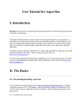
GENERAL PURPOSE SLAVE INTERFACE
MULTIBUS
Learning by example is often the most effective
means for absorbing technical information. With
. this idea in mind, a detailed description of a
general purpose slave interface (GPSI) has been
included in this application note. The description is
generally directed towards the implementation of
an I/O interface. However, the GPSI can also be
used as a slave memory interface by simply buffering the additional address signals and using the
appropriate MULTIBUS memory commands.
INTERFACE
~
ADRO/-AORF/
'-/
) \I
ADDRESS
DECODING
r
.
MRDC/
MWTC/
IORC/
IOWC/
DEVICE
SELECTS
~
I
C/D
BASE
ADDRESS
BD ENABLE/
RD/
WRT/
.
Y--
~
~
A
~
)
DATO/-DAT7/
BUS
DRIVERS
y
INTO/-INT7/
II
!\
~
XACK/
AACK/
This section briefly describes the organization of
the GPSI from two points of view. The principal
functions performed by the hardware are identified
and the general data flow is illustrated. This first
point of view is intended as an introduction to the
detailed information provided in the next section,
Theory of Operation. In the second point of view
the information needed by a programmer to access
the GPSI is summarized.
"" )
CONTRDL
LOGIC
A
The most significant aspect of the GPSI is that all
the information required to actually construct the
interface is contained in Appendix C. You can
make use of the schematic and wire list to prototype your application.
FUNCTIONAL/PROGRAMMING
CHARACTERISTICS
USER LOGIC
ACKNOWLEDGE
INTERRUPT
LINE
BUFFERS
I
8
f,.
L
'-/ V
BIDIRECTIONAL
DATA LINES
ACKND WLEDGE
'---~- INTERRUPT
.-----c-+-
REQUEST
LIN ES
Figure 6. GPSI Block Diagram
Effectively, this signal is used to select one of the
two 8 device address groups, yielding a total of 16
device addresses. The control/data line can also be
used directly with Intel peripheral chips such as
the 825l.
The GPSI may be configured to provide either
direct or memory mapped I/O for program access
to its devices. When direct I/O is used, the various
devices are accessed by the addresses shown in
Table 2.
Functional Description
The function of the GPSI is to provide bus interface logic which consists of those circuit elements
most directly involved with communication between the bus master and the GPSI. These elements include bus address/control line receivers,
bidirectional data buffer, device select decode
logic, transfer acknowledge generation, and line
driver circuits.
Table 2
GPSI ADDRESSING
DEVICE
C/D = 0
C/D = 1
1
XO
X1
2
X2
X3
3
X4
X5
4
X6
X7
5
X8
X9
6
XA
XB
7
XC
XD
8
XE
XF
A functional block diagram of the GPSI is shown
in Figure 6.
Programming Characteristics
The GPSI addressing provides 8 unique device
selects and a single line which may be used to
indicate control/data. The module's base address
is assigned through the use of wire wrap connections on the prototype board. Two such jumpers
are part of the board's address decode circuit for
system address bits ADR4/~ADR7/. They allow
the selection of a base address for the GPSI on a
l6-byte boundary. Address bits ADR1/~ADR3/
are decoded by other logic to provide 1 of 8 device
selects for the user. A single line to implement a
control/data select function is provided by ADRtp/.
X
~
Any hex digit; assigned by jumper; X is the same for all
GPSI devices.
When the GPSI is configured for memory mapped
I/O, the low order 8 bits of the 16-bit address are
identical to those shown in Table 2 for direct I/O.
However, the upper 8 bits of the address must be
all ones. Thus, the addressable devices occupy
space within the upper 256 bytes of memory,
FFtptp Hex to FFFF Hex.
10
The base address is decoded by an Intel 8205 one
of eight binary decoder (Ag). This device is enabled
by either ADR7/ or ADR7, as determined by the
wire-wrap connections. When enabled, Ag decodes
address bits ADR4/, ADR5/, and ADR6/ into one
of eight outputs. The base address enable (BASE
ADR/) may be taken from anyone of the eight Ag
outputs.
THEORY OF OPERATION
In . the preceding section each of the GPSI functional blocks was identified and briefly defined.
This .section explains how these functions are
implemented. For detailed circuit information,
refer to the GPSI schematic in Appendix C. The
schematic is on a foldout page so that you can
relate the following text to the schematic.
When the ADR4/ through ADR 7 / bits correspond
to the selected base address, an enable is provided
by Ag to a device select generator (A9) and the'
read/write command gates (Ad.
The GPSI contains those logic elements that
participate directly in the following types of
MULTIBUS activity.
1.
2.
3.
4.
5.
Bus address, control, and data buffering
Bus address decoding
Bus control signal propagation
Advance/Transfer acknowledge generation
Interrupt signal buffers.
The device select generator consists of an Intel
8205 decoder (A9) that is enabled by the base
address. When enabled, A9 decodes address bits
ADRI/, ADR2/, and ADR3/ into one of eight
device select outputs.
The five groups of logic responsible for these tasks
are described in the following paragraphs.
When memory mapped I/O is used, the high order
8 bits of the address bus are also decoded. The
address bits ADR8/ through ADRF/ are used as
inputs to a 74LS27 (A7). The outputs of A7 are
ANDed by a 74Sl0 (A2), producing an active low
output only when ADR8/-ADRF / are all active.
This output signal, MMIO/, is used to generate
optional inhibit signals as well as to enable the
memory read and write commands when a connection is made between A2-g and A4-3.
Bus Address, Control, and Data Buffers
Only one bit 'of the bus address is buffered and
passed directly onto the user logic. The rest of the
address bits are used to drive decoders. ADRf/J/ is
buffered by a 74LS02 (Al3). The control signal
buffer circuit consists of a 74S32 (AI) and a 74Sl0
(A2) for the memory and I/O read/write commands. These circuits are used to provide very high
switching speed.
The MMIO/ signal is inverted twice, first by a
74S04 (AI4) and then by 7406 open collector
drivers (A6). At that point the signal can be connected to the system INHI/ and/or INH2/ bus
signal lines.
The data buffers are formed by two Intel 8226
inverting bidirectional driver/receiver chips (AlO
and All). The system data bus is connected to the
device's DB pins. The DO and DI pins of each chip
can be connected to the user logic, providing either
an independent input and output bus or a bidirectional bus.
The only situation in which the inhibit lines are
required is if there is ROM or RAM in the system
which physically occupies the upper 256 bytes of
memory. When this is the case, you may choose to
disable the memory mapped I/O capability and use
direct I/O. Otherwise, you must select the proper
inhibit connection to allow use of the memory
mapped I/O. INHI/ is used to inhibit RAM, while
INH2/ inhibits ROM.
With a worst case delay of 53 nanoseconds, the
decode circuit that produces the inhibit signals
meets the bus AC requirement for inhibit delay
(tCI). However, the acknowledge of the inhibiting
slave (tACCB) is a much more difficult specification
to satisfy. The difficulty arises because the latest
possible acknowledgement from the inhibited slave
memory (tACCA) must be known to ensure an
adequate tACCB. In the worst case tACCB must be
at least 1.5 microseconds. The acknowledge delay
circuit, which will be described later, provides for
a maximum of approximately 800 nsec. In situa-
Directional control (DIEN/) for the 8226's is exercised by the I/O read command (lORC/) or the
memory read command (MRDC/) in situations
where memory mapped I/O is used. If the read
command is asserted by the bus master and the
module's base address is present, the data buffer's
receiver circuits are enabled.
The chip select (CS/) for the data buffer is enabled
when a command is gated onto the board.
Bus Address Decoding
The bus address decoding logic decodes the appropriate address bits into device selects. When memory mapped I/O is used, all ones on the high order
8 bits of the address are decoded. The GPSI logic
also produces an enable for the read/write command decode logic and the MULTIBUS inhibit
signals.
11
tions where a 1.5 Ilsec tACCB is required, the clock
frequency of the delay circuit must be halved or
another device added to extend the selectable
delay to 1.5 Ilsec. In this situation it may well be a
better choice to disable the memory mapped I/O
in favor of the simple direct I/O technique.
Advance/Transfer Acknowledge Generation
The advance/transfer acknowledge generation logic
provides a transfer acknowledge response, XACK/,
to notify the bus master that data has either been
accepted from the MULTIBUS (during a write
operation) or placed on the MULTIBUS (during a
read operation). An advance acknowledge response, AACK/, is also provided for use in certain
8080-based systems, where it can decrease by one
the number of Wait states needed to complete a
read or.write operation.
If the GPSI module is to reside in an Intel Microcomputer Development System (lntellec) the
memory mapped I/O capability must be disabled.
This restriction exists because the Intellec has
ROM program memory which occupies the entire
memory mapped I/O region (FFCPCPH to FFFFH)
and must not be overridden by the GPSI.
Both acknowledge responses are generated by A12,
an 8-bit serial in, parallel out shift register. When
enabled by CMD, A12 shifts CCLK/ pulses. This
produces a sequence of high true pulses at AI2'S Q
outputs. The outputs occur at approximately 100
ns intervals.
Bus Control Signal Propagation
The appropriate Q outputs are selected by wirewrap connections to the inputs of a pair of threestate gates (A3). These gates drive the XACK/ and
AACK/ outputs onto the MULTIBUS when
enabled by BD ENABLE/.
A pair of 74S32 OR gates (AI) buffer the MRDC/
(memory read command) and MWTC/ (memory
write command) inputs from the MULTIBUS.
These gates are enabled by the MMIO/ (memory
mapped I/O) signal from the high order address
decoder.
As mentioned in the previous discussion on inhibit
operations, the maximum of about 800 ns delay
provided by Al2 may not be adequate. This can be
extended by either using a flip-flop to pre-divide
CCLK/ or by adding a second shift register in series
with A12. Although both techniques douqle the
range, the first cuts the resolution in half.
The gated and buffered memory read and write
commands are then each ORed and buffered with
their respective I/O read and write commands by a
pair of 74S10 NAND gates (A2). The output of
these gates are active high read and write commands.
Interrupt Signal Buffers
The GPSI only provides buffering for the bus interrupt signal lines. Two 7406 open collector drivers
(As and A6) are used for this function.
These commands are passed on to the advance/
transfer acknowledge generator via NOR gate A13.
The output of Al3 is designated CMD/. CMD/ is
enabled by the decoded base address at OR gate
Al to produce the board enable. This signal, BD
ENABLE/, controls the three-state gates that drive
AACK/ and XACK/ onto the MULTIBUS. BD
ENABLE/ also controls the chip selects for the
data bus buffers.
The MULTIBUS interrupt signals should be driven
with levels rather than pulses, unless the bus master
has an edge triggered interrupt controller. The
user's logic must latch and hold the interrupt signal
until serviced by the bus master.
USER SELECTABLE OPTIONS
The output of the I/O and memory write buffer is
inverted with a 74S04 (AI4) and forwarded as
WRT/ to the user logic. This internal write enable
should be qualified at each of these destinations
by the appropriate device select.
In this section, each of the options available to the
user is reviewed and the specific information
required to implement the desired characteristic
is summarized.
The output of the I/O and memory read buffer is
inverted and then enabled by the decoded base
address at AI- The resulting internal read enable,
RD/, is applied to the user logic and to the direction control (DIEN) on the bidirectional bus driver
chips (AlO and All).
Base Address Selection
The GPSI's base address is selected by wire-wrap
connections from one of the output pins of A8 to
an enable input (E2) of A9. Table 3 identifies the
base address that is implemented for each jumper
combination.
12
Table 3
BASE ADDRESS SELECTION
FROM
TO
FROM
TO
BASE
ADDR
FROM
TO
FROM
TO
BASE
ADDR
P1-52
A8-6
A8-7
A9-5
00
P'1-52
A8-5
A8-7
A9-5
80
GND
A8-5
A8-9
A9-5
10
A4-1
A8-6
A8-9
A9-5
90
AO
80
A8-10
A9-5
20
A8-10
A9-5
A8-11
A9-5
30
A8-11
A9-5
A9-5
CO
A8-12
A9-5
40
A8-12
A8-13
A9-5
50
A8-13
A9-5
DO
A8-14
A9-5
60
A8-14
A9-5
EO
A8-15
A9-5
70
A8-15
A9-5
FO
Advance/Transfer Acknowledge Timing
because of the skew introduced into the acknowledge circuit by the use of CCLK/ to drive A12.
Actual time values for these periods depend, of
course, on the frequency of CCLK/. For the SBC
80/10 or 80/20 bus masters, CCLK/ is 9.216 MHz,
which provides a clock period of 108.5 nanoseconds.
The GPSI's advance acknowledge and transfer
acknowledge response timing is selected in approximately 100 ns increments by wire-wrap connec'tions at the outputs of A12- Table 4 shows the
range of response timing for each possible connection in terms of CCLK/ periods. This range occurs
Table 4
ADVANCE/TRANSFER ACKNOWLEDGE TIMING
DELAY FROM RECEIPT OF CMD
TO ACK GENERATION
PIN CONNECTIONS
XACK
AACK
FROM:
TO:
FROM:
TO:
A4-4
A3-12
A4-4
A3-14
Immediate
A12-3
A3-12
A12-3
A3-14
o to
A12-4
A3-12
A12-4
A3-14
1 to 2
A12-5
A3-12
A12-5
A3-14
2 to 3
A12~6
A3-12
A12-6
A3-14
3 to 4
A 12-10
A3-12
A12-10
A3-14
4 to 5
A 12-11
A3-12
A 12-11
A3-14
5 to 6
A 12-12
A3-12
A 12-12
A3-14
6 to 7
A 12-13
A3-12
A 12-13
A3-14
7 to 8
13
1
CCLK/ Periods
CCLK/ Periods
PROTOTYPING APPLICATIONS
SUMMARY
The GPSI should be well suited for most prototyping applications by constructing the interface on a
SBC 905 Universal Prototype Board. A complete
wire list is provided in Appendix C to further
simplify the task. The complete general purpose
slave interface requires 14 IC's and can best be laid
out by placement from left to right, AI-A14,
across the bottom of the SBC 905 (Figure 7).
Using the GPSI constructed on an SBC 905, you
have the capacity for an additional 80 16-pin locations for wire-wrap sockets or the equivalent mix
of 14,16, 18,22,24,28 or 40-pin sockets.
This application note has shown the structure of
the Intel MULTIBUS. The structure supports a
wide range of system modules from the Intel OEM
Computer Product Line that can be extended with
the addition of user designed modules. Because the
user designed modules are no doubt unique to
particular applications, a goal of this application
note has been to describe in detail the singular
common element - the bus interface. Material
has also been presented to assist the systems
designer in understanding the bus functions so that
successful systems integration can be achieved.
SBC-905
(COMPONENT SIDE)
Figure 7. Prototype Board Layout
14
APPENDIX A
MUL TIBUS PIN ASSIGNMENT
(CIRCUIT SIDE)
(COMPONENT SlOE)
PIN
Power
Supplies
Bus
Controls
MNEMONIC
DESCRIPTION
PIN
MNEMONIC
DESCRIPTION
1
3
5
7
9
11
GND
+5
+5
+12
-5
GND
Signal GND
+5 VDC
+5 VDC
+12 VDC
-5 VDC
Signal GND
2
4
6
8
10
12
GND
+5
+5
+12
-5
GND
Signal GND
+5VDC
+5VDC
+12 VDC
-5VDC
Signal GND
13
15
17
19
21
23
25
BCLK/
BPRN/
BUSY/
MRDC/
IORC/
XACK/
AACK/
Bus Clock
Bus Priority In
Bus Busy
Memory Read Command
I/O Read Command
XFER Acknowledge
Special Acknowledge
14
16
18
20
22
24
26
INIT/
BPRO/
BRED/
MWTC/
10WC/
INH1/
INH2/
Reserved
Reserved
Constant Clk
Reserved
28
30
32
34
Initialize
Bus Priority Out
Bus Request
Memory Write Command
I/O Write Command
Inhibit 1 Disable RAM
Inhibit 2 Disable PROM or
ROM
Reserved
Reserved
Reserved
Reserved
Parallel Interrupt Requests
36
38
40
42
INT7/
INT5/
INT3/
INT1/
44
46
48
50
52
54
56
58
ADRF/
ADRD/
ADRB/
ADR9/
ADR7/
ADR5/
ADR3/
ADR1/
60
62
64
66
68
70
72
74
DATF/
DATD/
DATB/
DAT9/
DAT7/
DAT5/
DAT3/
DAT1/
76
78
80
82
84
86
GND
-10*
-12
+5
+5
GND
27
29
31
33
CCLK/
Interrupts
35
37
39
41
INT6/
INT4/
INT2/
INTO/
Address
43
45
47
49
51
53
55
57
ADRE/
ADRC/
ADRA!
ADR8/
ADR6/
ADR4/
ADR2/
ADRO/
Data
59
61
63
65
67
69
71
73
DATE/
DATC/
DATA/
DAT8/
DAT6/
DAT4/
DAT2/
DATO/
Power
Supplies
75
77
79
81
83
85
GND
-10*
-12
+5
+5
GND
Address Bus
Data Bus
Signal GND
-10 VDC
-12 VDC
+5 VDC
+5VDC
Signal GND
*For MDS 800 compatibility.
15
Parallel Interrupt Requests
Address Bus
Data Bus
Signal GND
-10 VDC
-12 VDC
+5VDC
+5VDC
Signal GND
APPENDIX B
MUL TIBUS DC REQUIREMENTS
DRIVER
BUS SIGNALS
LOCATION
LOAD PER BOARD
DRIVE (Min)
LOCATION
SOURCING (Max)
PULL-UP/DOWN
RESISTOR
INIT/
Master
TTL, 32 mA
All
1.8 mA
None
BCLK/, CCLK/
Master
TTL, 48 mA
Master
2.0mA
220/330,Q termination
on Motherboard
BRED/
Master
TTL, 16 mA
2.0mA
1 k,Q pull-up on
Motherboard
BPRN/
Master
TTL, 16 mA
Master
2.0mA
None
BPRO/
Master
TTL, 32 mA
Master
2.0mA
None
BUSY/
Master
OC, 20 mA
Master
2.0mA
1.0 k,Q pull-up
MRDC/, MWTC/
Master
TRI, 32 mA
Slave
2.0mA
1.1 k,Q pull-up
10RC/, 10WC/
Master
TRI, 32 mA
I/O Board
2.0mA
1.1 k,Q pull-up
XACK/, AACK/
Slave
TRI, 16 mA
Master
2.0mA
510 ,Q pull-up
DATF /-DAnA/
Master
TRI, 15 mA
Slave
0.5 mA
2.2 k,Q pull-up
ADRF/-ADR0/
Master
TRI, 15 mA
Slave
0.5mA
2.2 k,Q pull-up
INH1/,INH2/
All
~C,
RAM, PROM,
Memory
Mapped I/O
2.0mA
1 k,Q pull-up
INn/-INT0/
All
OC,16 mA
Master
2.0mA
1 k,Q pull-up
NOTES: 1. Input voltage levels:
16 mA
High 2.4V to 5.0V
Low O.OV to O.BV
2. Output voltage level: High 2.0V to 5.25V
Low O.OV to 0.45V
OC - open collector
TTL - totem-pole output
TRI - three-state
3. Leakage current of an input ~40 p.A
Leakage current of an output';; 100 p.A
4. Maximum number of Master devices = 16 using parallel priority network.
5. Maximum bus capacitance is 300 pF.
16
APPENDIX C
GPSI INTERFACE SCHEMATIC AND WIRE LIST
(FOLDOUT)
17
GPSI WIRE LIST
SIGNAL NAME
BOTTOM
GENERAL-PURPOSE SLAVE BUS INTERFACE
SIGNAL NAME
BOTTOM
TOP
ADRO/
P1·57
A13·2
BASE ADR/
A9·5
A1·4
A1·4
A1·1
4' INTO/
ADR1/
P1·58
A9·1
RD/
A1·6
~
A11·15
A11·15
A1O·15
4' INT1/
~
BD ENABLE/
A1·3
A3·15
A3·15
A11·1
39 INT'/
~
A11·1
A10·1
401NT3/
E----<>
ADR2/
P1·55
A9·2
ADR3/
P1·56
A9·3
ADR4/
P1·53
A8·1
8A7
A7·8
A2·9
371NT4/
~
ADR5/
P1·54
A8·2
6A7
A2·10
~
ADR6/
P1·51
A8·3
12A7
A7·6
A7·12
381NT5{
A2·11
35 INT6/
E----<>
A4·3
A14·3
ADR8/
P1·49
A7·9
A7·10
MMIO/
A14·3
A1·12
P1·50
P1·47
A7·11
4A14
A14·4
A6·1
A6·1
A6·3
ADRB/
A7·3
11A1
A1·11
A2·1
A2·1
ADRC/
P1·48
P1·45
A7·4
8A1
A1·8
A2·3
A2·3
A2·2
A2·4
ADRD/
P1·46
A7·5
12A2
A2·12
A14·9
A14·9
A13·5
ADRE/
P1·43
A7·1
6A2
A2·6
A14·5
A14·5
A13·6
ADRF/
P1·44
A7·2
8A14
A14·8
A1·5
MRDC/
P1·19
A1·13
A1·2
P1·20
A1·9
CMD/
2A14
A13·4
MWTC/
A14·2
A12·9
IORC/
P1·21
A2·13
A1·10
P1·22
A4·4
A12·1
P1·31
A2·5
A12·8
4A4
CCLK
INIT
A3·3
A3·4
INIT/
P1·14
A3·2
6A9
A9·6
A4·2
XACK/
P1·23
P1·25
A3·11
DATAO/
P1·73
A11·3
DATA1/
P1·74
DATA2/
DATA3/
P1·71
A1·2
A12·1
,'\ORRI
A12·2
45 ADRC/
46 ADRDI
A4·16
A1·14, A2·14, A14·14, A3·16, A7·14
A11·10
A6·14, A5·14, A13·14
P1·70
A10·6
A8·8, A9·8, A11·8, A10·8, A12·7
P1·67
A10·10
DATA7/
P1·68
A10·13
A1·7, A2·7, A14·7, A3·8, A7·7
A6·7, A5·7, A13·7
-t
9
P!;\-o
p!%---o
7
B
A7
6
,
A7
'0
"
"'r
,
A,
B
A8
8205
A2
74S10
A9
8205
A3
8098
A10
8226
A4
1K-RP
A11
8226
A5
7406
A12
74164
A14
6
E3
5
E,
E,
0S4/
OS5/
OS6/
oS7/
8205
A4
3
MMIO/
'2
~
~47~
3 A'4
7~
-=-
,
A
4
'
A6
~11
13
A,
,
,
22 lowel
,
74LS02
74S04
74S32
A,
-='~
9
21 IORC/
-
l
'~~O
~A,
5-
~6
5 A,
74504
1 74510
,
A,./
~"
9 A'4
B
74504
6
I
6
5 A'4
WAT/
74532.
5 ---l4LS02
~A13
..........
~3
,
A,
CMO/
,
4
':cc
74504
,"
,,
9
eLR A8 0A
8
~
2
23 XACK!
25 AACK/
3
A3
14 INITI
4·
A3
DB
DC
DO
elK A12 0E
DF
DG
5
-4--
BD ENABLE/
~
,
CCLK
RD/
~
A'4
31
A13
OS3/
"
Vcc
,"
9 74510
3
OSO/
DS1!
oS2/
BASE ADRI
"
>--.
t
8205
'5
'4
'3
,
,
3 12
4
5 '0
9
6
7
7
A9
6~--o
7
74LS27
>-~A7
~
"tVcc
:4
lK
A3·1, A7·13, A8·4, A9·4, A13·3
PARTS LIST
74LS27
6
E3
5
E,
E,
4
5
-1
o
AO
A,
A,
74832
A11·6
7406
AB
~
I
3~-o
rcc
~4
)-0
'5
,~
,~
3 A,'
'3
20 MWTC!
74S32
!1:0
43 ADRE/
44 ADRF/
19MRDC/
VSS
o
26 INH2/
DATA5/
DATA6/
A6
A7
4Z)
C/O
-
47 ADAA/
A11·13
A1
A14·1
A8·16, A9·16, A11·16, A10·16, A12·14
A10·3
,
AS "3
lK
E"O :'\0'19/
P1·72
P1·69
DATA4/
E---o
24 lNH1/
VCC
(XINTR6
~~~I ,..._ _ _ _ _ _ _ _ _ _ _ _ _ _ _ _ _ _ _ _ _ _ _ _ _ _ _ _ _ _ _ _---«XINTR7
0-----_
A5
1.
A3·13
AACK/
'~ ~---------------------------------(XINTR5
> -_ _-.;
53 ADR4/
54 ADRSI
51 ADR6/
48 ADRB/
IOWC/
o-----~o('
A51_:,-.-::..----------------------------------«XINTR'
~------------------------------------«XINTR3
>----~1..,,5---==-------------------------·------------«XINTR4
0
55 ADR2/
56 ADR3/
52 ADR71
XINTRO
- - - - - - -_ _ _ _ _ _ _ _ _ _ _ _ _ _ _ _ _ _ _ _ _ _ _ _ _---«XINTR'
>-------'-O(~I-:;-:-,
~~ ~~~~; )>------------.::-----------------------?8I-'~-4L-SO-'--------7)
ADR9/
ADRA!
A1·12
36 INT71
o_-~~;.;-~v:1--------------------------------------«
74'64 °H
~
~
~
f-!;!;-....o
~
f2L-o
A4
'€
12
0-
A3
11
AACK/
8098
~
14
A3
13
XACK/
BO INIT/
BO INIT
(
'\'
CS
3
73 DATAOI
6
74 DATA1f
71 DATA2!
'0
72 DATAl
'3
DBO
01 0
000
DI,
DB, A"
DO,
8226 01 2
DB,
DO?
01
3
DB3 DlENo03
,
4
7
5
9
11
12
,.
OBINO
OBOUTO
OBIN1
OBoun
OBIN2
OBOUT2
OBIN3
OBOUT3
'5
cs
3
69 DATA4!
6
70 DATASI
'0
67 DATA6!
68 DATA7!
08 0
)(
'3
,
01 0
000
01,
DB, A,O DO,
8226 002
01 2
DB2
01 3
DB3D1ENo03
y
,
4
7
5
9
11
12
'4
OBIN4
DBOUTtI
OBIN5
OBOUT6
OUINII
onouro
OBIN]
OIJOUT7
APPENDIX D
MECHANICAL SPECIFICATIONS
12.00
0.25 X 45 0
2 PLACES
±O.OOS
11.500
~
,
~ 0.25
~
0.25
0
01-.-----
0.109 DI A /
3HOL ES
5.950
iO.OOS
COMPONENT SIDE
D>
6.20
6.7 5 REF
[3>
----
0.0 6R
T YP
I.
D>
HI
j;I
6.767 ±0.005
I.
. 1.
01-
- - - n r1-- 13.080
4.570
.1'
0.55
L
O.30
~ 0.390
CHAMFER ALL
CONNECTOR EDGES
0,015 ± 0.005 X 450
2 PLACES
0.040 X 45°
NOTES:
BOARD THICKNESS: 0.062
MULTIBUS CONNECTOR: 8S-PIN. 0.156 SPACING
CDC VFBOl E43DOOA 1
VIKING 2VH43/1ANE5
AUXILIARY CONNECTOR: 60·PIN, 0.100 SPACING
CDC VPBOl B30DOOA 1
TI H311130
AMP PE5·14559
EJECTOR TYPE: SCANBE #S203
5.
BUS DRIVERS AND RECEIVERS SHOULD BE LOCATED AS CLOSE AS POSSIBLE TO
THEIR RESPECTIVE MULTIBUS PIN CONNECTIONS
6.
BOARD SPACING: 0.6
7.
COMPONENT HEIGHT: 0.435
8.
CLEARANCE ON CONDUCTOR NEAR EDGES: 0.050
18
Intel MULTI BUS Interfacing
AP-28
REQUEST FOR READER'S COMMENTS
The Microcomputer Division Technical Publications Department attempts to provide documents that meet the needs of all
Intel product users. This form lets you participate directly in the documentation process.
Please restrict your comments to the usability, accuracy, readability, organization, and completeness of this document.
1.
Please specify by page any errors you found in this manual.
2.
Does the document cover the information you expected or required? Please make suggestions for improvement.
3.
Is this the right type of document for your needs? Is it at the right level? What other types of documents are needed?
4.
Did you have any difficulty understanding descriptions or wording? Where?
5.
Please rate this document on a scale of 1 to 10 with 10 being the best rating. _ _ _ _ __
NAME ______________________________________________________ DATE _________ ________________
TITLE _____________________________________________________________________________________
~
COMPANYNAME/DEPARTMENT ______________________________________________________________________
ADDRESS _____________________________________________________________________________________
CITY______________________________________ STATE __________________ ZIPCODE __________________
Please check here if you requ ire a written reply. 0
WE'D LIKE YOUR COMMENTS ...
This document is one of a series describing Intel software products. Your comments on the back of this form
will help us produce better software and manuals. Each reply will be carefully reviewed by the responsible
person. All comments and suggestions become the property of Intel Corporation.
First Class
Permit No. 1040
Santa Clara, CA
BUSINESS REPLY MAIL
No Postage Stamp Necessary if Mailed in U.S.A.
Posrage will be paid by:
Intel Corporation
3065 Bowers Avenue
Santa Clara, CA 95051
Attention: MCD Technical Publications
MICROCOMPUTER AND MEMORY SYSTEM
SALES AND MARKETING OFFICES
3065 Bowers Avenue
Santa Clara, California 95051
Tel: (408) 246-7501
TWX: 910-338-0026
TELEX: 34-6372
u.s. AND CANADA SALES OFFICES
ALABAMA
Col-Ins-Co
2806 Broadview Drive
Huntsville 35810
Tel: (BOO) 327-6600
CONNECTICUT
Intel Corp.
8 Mill Plain Road
Danbury 06810
Tel: (203) 792-8366
ARIZONA
Sales Engineering, Inc.
7228 Stetson Drive, Suite 34
Scottsdale 85252
Tel: (602) 845-5781
TWX: 910-950-1288
FLORIDA
Intel Corp.
2020 W. McNab Road, Suite 104
Ft. Lauderdale 33309
Tel: (305) 971-7200
TWX: 510-956-9407
Intel Corp.
5151 Adanson Street, Suite 105
Orlando 32804
Tel: (305) 628-2393
TWX: 810-653-9219
Col-ins-Co
1313 44th Street
Orlando 32809
Tel: (305) 423-7615
BFA
4426 North Saddle Bag Trail
Scottsdale 85251
Tel: (602) 994-5400
Intel Corp.
8650 N. 35th Avenue
Phoenix 85021
Tel: (602) 242-7205
CALIFORNIA
Intel Corp,990 E. Arques Ave.
Suite 112
Sunnyvale 94086
Tel: (408) 738-3870
TWX: 910-339-9279
TWX: 910-338-0255
Mac-I
P,O. Box 1420
Cupertino 95014
Tel: (408) 257-9880
Intel Corp.·
1651 East 4th Street
Suite 228
Santa Ana 92701
Tel: (714) 835-9642
TWX: 910-595-1114
Mac-I
11725 Aspen
Fountain Valley 92708
Tel: (714) 839-3341
Mac-I
22935 Erwin Street
Woodland Hills 91364
Tel: (213) 347-1374
Earle Associates, Inc.
4805 Morcury Street
Suite L
San Diego 92111
Tel: (714) 278-5441
GEORGIA
Col-Ins-Co
1280 Cedar Park Circle
Stone Mountain 30083
Tel: (800) 327·6600
ILLINOIS
Intel Corp."
1000 Jorle Boulevard
Suite 224
Oakbrook 60521
Tel: (312) 325-9510
TWX: 910-651-5881
Data Electronics
4976 North Milwaukee Avenue
Chicago 60630
Tel: (312) 263-0300
INDIANA
Data Electronics
2920 Shelby Avenue
Indianapolis 46203
Tel: (317) 784-6360
IOWA
Technical Representatives, Inc.
1703 Hillside Drive N/W
Cedar Rapids 52405
Tel: (319) 396-5662
KANSAS
Technical Representatives, Inc.
801 Clalrborne
Olathe 66061
Tel: (913) 782-1177
TWX: 910-749-6412
COLORADO
Intel Corp.
12075 East 45th Avenue
Suite 310
Denver 80239
Te[: (303) 373-4920
TWX: 910-932-0322
BFA Corporation
850 Lincoln Street
Denver 80203
Tel: (303) 837-1247
TWX: 910-931-2205
MARYLAND
Glen White Associates
57 West Timonium Road
Timonium 21093
Tel: (301) 252-7742
Intel Corp.57 West Timonium Road
Suite 307
Timonium 21093
Tel: (301) 252-7742
TWX: 710-232-1807
MARYLAND (cont.)
Mesa Inc,
11900 Parklawn Drive
Rockville 20B52
MASSACHUSETTS
Intel Corp.187 Billerica Road, Suite 14A
Chelmsford 01824
Tel: (617) 256-6567
TWX: 710-343-6333
Computer Marketing Associates
235 Bear Hili Road
Waltham 02154
Tel: (617) 890-1776
MICHIGAN
Intel Corp.
26500 Northwestern Hwy.
Suile 401
Southfield 48075
Tel: (313) 353-0920
TWX: 910-420-1212
TELEX: 2 31143
Lowry & Associates, Inc.
135W. North Street
Suile 4
Bri9hton 48116
Tel: (313) 227-7067
MINNESOTA
Intel Corp,
8200 Normandale Avenue
Suite 422
Bloomington 55437
Tel: (612) 835-6722
TWX: 910-576-2867
Data Electronics
P,O. Box 32087
7340 Melody Drive
Minneapolis 55432
Tel: (612) 786-9666
MISSOURI
Technical Representatives, Inc.
Trade Center Bldg.
300 Brookes Drive, Suite 108
Hazelwood 63042
Tel: (314) 731-5200
TWX: 910-762-0618
NEW JERSEY
Intel Corp.
2 Kilmer Road
Edison 08617
Tel: (201) 985-9100
TWX: 710-480-6238
NEW MEXICO
BFA Corporation
312 West Parker Road
Las Cruces 88001
Tel: (505) 523-0601
TWX: 910-963-0543
BFA Corporation
3705 Westerfield, N.E.
Albuquerque 87111
Tel: (505) 292-1212
TWX: 910-989-1157
NEW YORK
Intel Corp.".
350 Vanderbilt Motor Pkwy.
Suite 402
Hauppauge 11787
Tel: (516) 231-3300
TWX: 510-221-2198
Intel Corp.
474 Thurston Road
Rochester 14619
Tel: (716) 328-7340
TWX: 510-253-3841
T-Squared
4054 Nowcourt Avenue
Syracuse 13206
Tel: (315) 463-8592
TWX: 710-541-0554
T-Squared
640 Kreag Road
P.O. Box W
Pittsford 14534
Tel: (716) 361-2551
TELEX: 97·8289
Intel Corp.
85 Market Street
Poughkeepsie 12601
Tel: (914) 473-2303
TWX; 510-248·0060
Measurement Technology, Inc.
159 Northern Boulevard
Great Neck 11021
Tel: (516) 482-3500
NORTH CAROLINA
Col·lns-Co
2873 Monticello Drive
Winston-Salem 27106
Tel: (800) 327-6600
OHIO
Intel Corp.8312 North Main Street
Dayton 45415
Tel: (513) 890-5350
TELEX: 288-004
Intel Corp.26250 Euclid Ave.
Suite 531F
Euclid 44132
Tel: (216) 289-0101
Lowry & Associates, Inc.
42 East Rahn Road
Suite 100
Dayton 45429
Tel: (513) 435-4795
Lowry & Associates, Inc.
24200 Chagrin Blvd.
Suite 146
Cleveland 44122
Tel: (216) 464-8113
OREGON
ES/Chase Company
P.O. Box 602
Beaverton 97005
Tel: (503) 642-2732 or 228-2521
PENNSYLVANIA
Intel Corp.·
520 PennsylvanIa Ave.
Fori Washington 19034
Tel: (215) 542·9444
TWX: 510-661-0709
Q.E.D. Electronics
300 N. York Road
Hatboro 19040
Tel: (215) 674·9600
Lowry & ASSOCiates, Inc.
Three Parkway Center
Suite 201
Pittsburgh 15220
Tel: (412) 922-5110
TEXAS
Mycrosystems Marketing Inc.
13777 N, Central Expressway
Suite 405
Dallas 75231
Tel: (214) 238-7157
TWX: 910-867-4763
MycrosYstems Marketrng Inc.
6610 Harwln Avenue, Suite 125
Houston 77036
Tel: (713) 783-2900
Mycrosystems Marketing Inc.
2622 Geronimo Trail
Austin 78746
Tel; (512) 266-1750
Intel Corp.·
2925 L.B.J. Freeway
Suite 100
Dallas 75234
Tel: (214) 241-9521
TWX: 910-860-5487
UTAH
BFA Corporation
395 Lawndale Drive
Salt Lake City 84115
Tel: (801)466-6522
TWX: 910-925-5666
WASHINGTON
E.S./Chase Co.
P.O. Box 80903
Seattle 98106
Tel: (206) 762-4824
TWX: 910-444-2298
CANADA
Intel Corp.
70 Chamberlain Ave.
Ottawa, Ontario K1S 1V9
Tel: (613) 232-8576
TelEX: 053-4419
Multilek, Inc.4 Barran Street
Ottawa, Ontario K2J lG2
Tel: (613) 825-4553
TELEX: 053-4585
EUROPEAN MARKETING OFFICES
BELGIUM
Intel International·
Rue du Moulin a Papier
51-Bolte 1
B-1160 Brussels
Tel: (02) 660 30 10
TELEX: 24814
FRANCE
Intel Corporation, SAR.L·
74, Rue D'Arcueil
Sillc 223
94528 Rungls Cedex
Tel: (01) 687 22 21
TELEX: 270475
SCANDINAVIA
Intel Scandinavia A/S·
Lyn9byvej 32 2nd Floor
DK-2100 Copenhagen East
Denmark
Tel: (01) 18 20 00
TELEX: 19567
Intel Sweden AB·
Box 20092
S-16120 Bromma
Sweden
Tel: (08) 98 53 90
TELEX: 12261
ENGLAND
Intel Corporation (UK) Ltd.·
Broadfield House
4 Between Towns Roaci
Cowley, Oxford OX4 3NB
Tel: (0865) 77 1431
TELEX: 837203
Intel Corporation (U.K.) Ltd.
46-50 Beam Street
Nantwich, Cheshire CW5 5LJ
Tel: (0270) 62 65 60
TELEX: 36620
GERMANY
Intei Semiconductor GmbHSeldlstrasse 27
8000 Muenchen 2
Tol: (089) 55 81 41
TELEX: 523 177
Intei Semiconductor GmbH
Abraham Lincoln Strasse 30
6200 Wiesbaden 1
Tel: (06121) 74855
TELEX: 04186183
Intel Semiconductor GmbH
0-7000 Stuttgart 80
Ernsthaldenstrasse 17
Tel: (0711) 7351506
TELEX: 7255346
HONG KONG
ASTEC International
Oriental Centre
14th Floor, No. 67-71
Chatham Road
Kowloon, Hong Kong
Tel: 3-694751
Cable: "ASCOMP"
TELEX: 74699 ASCOM HX
JAPAN (cont)
Ryoyo Electric Corp.
Konwa Bldg.
1-12-22, Tsukiji, 1-Chome
Chuo-Ku, Tokyo 104
Tel: (03) 543-7711
Nippon Micro Computer Co. Ltd.
Mutsumi Bldg. 4-5-21 Kojimachi
Chiyoda-ku, Tokyo 102
Tel: (03) 230-0041
SOUTH AFRICA
Electronic Buliding Elements
P.O. Box 4609
Pretoria
Tel: 78 92 21
TELEX: 30181
ORIENT MARKETING OFFICES
JAPAN
Intel Japan CorporationFlower HIII-Shinmachl East Bldg.
1-23-9, Shlnmachi, Setagaya-ku
Tokyo 154
Tel: (03) 426-9261
TELEX: 781-28426
TAIWAN
Taiwan Automation Co,6th Floor, 18-1, Lane 14
Chi-Lin Road
Taipei
Tel: {02} 551726-9
TELEX: 11942 TAIAUTO
INTERNATIONAL DISTRIBUTORS
ARGENTINA
S.I.E.S.A.
Av. Pte. Rogue Saenz Pena 1142 9B
1035 Buenos Aires
Tel: 35-6784
AUSTRALIA
A. J. Ferguson (Adelaide) PTY, ltd.
44 Prospect Rd.
Prospect 5082
South Australia 17005
Tel: 269-1244
TELEX: 82635
A. J. Ferguson Electronics
34 Herbert Street
West Ryde, N.S.W. 2114
Tel: AC8 269-1244
TELEX: 82635
Warburton-Frankie (Sydney) Pty. Ltd.
199 Parramatia Road
Auburn. N.S.W. 2114
Tel: 648-1711, 648-1381
TELEX: WAR FRAN AA 22265
Warburton-Frankie Industries
(Melbourne) Pty. Ltd.
220 Park Street
South Melbourne, Victoria 3205
AUSTRIA
Bacher Elektronische Gerate GmbH
MeidlJnger Hauptstrasse 76
A 1120 Vienna
Tel: (0222) 836396
TelEX: (01) 1532
BELGIUM
Inelco Belgium SA
Avenue Val Duchesse, 3
B-1160 Brussels
Tel: (02) 660 00 12
TELEX: 25441
DENMARK
Scandinavian Semiconductor
Supply A/S
Nannasgade 18
OK-2200 Copenhagen N
Tel: (01) 93 50 90
TelEX: 19037
FINLAND
Oy Fintronlc AB
Loennrotlnkatu 350
SF 00180
.
Helsinki 18
Tel: (90) 664 451
TELEX: 12426
FRANCE
Tekelec Alrtronlc
Cite des Bruyeres
Rue Carle Vemet
92310 Sevres
Tel: (1) 027 75 35
TELEX: 250997
GERMANY
Alfred Neye Enatachnik GmbH
Schillerstrasse 14
0-2085 Quickborn-Hambuig
Tel: (04106) 6121
TELEX: 02-13590
Electronic 2000 Vertriebs GmbH
Neumarkter Strasse 75
0-8000 Muenchen 80
Tel: (089) 434061
TELEX: 522561
Jermyn GmbH
Postfach 1146
D-6277 Kamberg
Tel: (06434) 6005
TELEX: 484426
INDIA
Electronics International
128 Mahatma Gandhi Road
Secunderabad
Tel: 53211
TelEX: 043-222
ISRAEL
Eastronlcs Ltd.·
11 Rozanls Street
P.O. Box 39300
Tel-Aviv
Tel: 475151
TELEX: 33638
ITALY
Eledra 3S S.P.A.·
Viale Elvezla, 16
20154 Milan,
Tel: (02) 3493041
TELEX: 39332
Eledra 3S S.PA·
Via Paolo Galdano, 141 0
10137 Torino
TEL: (011) 30 97 097 - 30 97114
Eledra 3S S.PA·
Via Giuseppe Val marana, 63
00139 Rome, Italy
Tel: (06) 81 27290 - 81 27324
TELEX: 63051
JAPAN
Pan Electron
No.1 Higashlkata-Machi
Mldorl-Ku, Yokohama 226
Tel: (045) 471-8811
TELEX: 781-4773
KOREA
Koram Digital
Sam Yung Bldg. #303
71-2 Bukchan9 - Dong Chung-Ku
Seoul 100
NETHERLANDS
C.N. Rood BV
Cort Vender
Lindenstraat, 13
Postbus 42
Rijswijk 2H2100
Tel: 070-996360
TELEX: 31238
Inelco Nederland
AFD Elektronic
Joan Muyskenweg 22
NL-1006 Amsterdam
Tel: (020) 934824
T~LEX: 14622
NORWAY
Nordisk Elektronik (Norge) A/S
Mustads Vei 1
N-Oslo 2
Tel: (02) 55 38 93
TE.LEX: 16963
PORTUGAL
,Dltram
Componentes E Electronlca LOA
Av. Miguel Bombarda, 133
lisboa 1
Tel: 11945313
SPAIN
Interface
Ronda San Pedro 22
Barcelona 10
Tel: 301 7851
SWEDEN
Nordisk ElectronJk AB
Fack
5-10380 Stockholm 7
Tel: (08) 248340
TELEX: 10547
SWITZERLAND
Industrade AG
Gemsenstrasse 2
Postcheck 80 - 21190
CH-8021 Zurich
Tel: (01) 60 22 30
TELEX: 56788
UNITED KINGDOM
Rapid Recall, Ltd.
11-15 BeUerton Street
Drury Lane
London WC2H 9BS
Tel: (01) 379-6741
TELEX: 28752
G.E.C. ,Semiconductors Ltd.
East Lane
Wembley HA9 7PP
Middlesex
Tel: (01) 904-9303
TELEX: 923429
Jermyn Industries
Vestry Estate
Sevenoaks, Kent
Tel: (0732) 50144
TELEX: 95142
*Field Application Location
inter
INTEL CORPORATION, 3065 Bowers Avenue, Santa Clara, CA 95051 (408) 246-7501
Printed in U,S,A./S236/0777/IOK B L