1
Technische Universiteit
tlB
Eindhoven
Faculty of Electrical Engineering
Section of Digital Information Systems
Master's Thesis:
Cordless LAN solution using DECT
Specifications and design of a DECT PC-card
Erwin Slob en Dirk-Jan Riezebos
Coach:
Supervisor:
July 1995
ir. F.A.J. Dumont (Philips Semiconductors)
Prof.dr.ir. C.J. Koomen
The Faculty of Electrical Engineering of Eindhoven University of Technology does not
accept any responsibility regarding the contents of Master's Theses.
Philips Semiconductors
Product Concept and Application Laboratory Eindhoven (pCALE)
Telecommunication Division
Eindhoven University of Technology (TUB)
Faculty of Electrical Engineering
Section: Digital Information Systems (EB)
Graduation Report
Cordless LAN solution using DECT
Specifications and design of a DECT PC-card
By Erwin Slob and Dirk-Jan Riezebos
,oW
.
iEi
!r.ol~ ~ ~* .. jBggBIQI
DO
~
~
.._
I ;-.-'-'-:
....
11
>~~L::~~'IV~!
'~"I ')1 ~~~ ~ 51 ::::. j5l1
I~a '(~~:"je~~ u ~''''M ~
~~~ I~ i~~di]I'
10- ~.iI
~
:8&
!~
]
I ~~~:··:::··:~~~i ' ~~~:··:::··:grtiJ ~~~:·~::":~~L,.r.q:...~.:
, ••••,g
i!·'
m····, ....
.... " ....
.... ~I
~
I::::
::::1 :::::~ m:::: ::::
!!J::::, ,_
+---:;::I,i:::
ill • •Ej
:::: '::: Bill:::: :::
:::' i S i!
,I
~I!""
• • • • • . • • • • • • • • • • .,
•••••••••••. :
1>•• !
II
1:::::::::::::::
:/ : ,
,; ;
, '
,;; :::
' :!._~,
, §d::§-::3-§J'=
/=:!
i!!J
f
:.,
! :::::::::::::::,'::::::::::::::::1I :::::::::::::::.
1 ::::::::::::::::
[
~
•-tIIIiJ
... 1 •••••••••
••••••• 1"
II~"~:
,.~
m;·... ··~~ .. ·M.
II" ~II ..D
g~a •-/1
. .
I
L'!
Ii
i
!","
I
: ::::::::::::::::
•
s(
'I :::::::::1:
:1 ....... 11
I:.. == ,=::== •==1'==
,:l
11
il~~.~··~~i, ~
=----"~.&~=i~l~
- i::-~~ '" --=,
(':::::::' ,I
r:::~:~~i::f:C;::LJ
•••••••••••••• 3'_
·
'.
om
"Ii' ... .....• ...•.
.::=
go
""""'"
ml
I'" :
--lIlWlIl1lIL- 1
§ -§
]
.~-I
! ••
~
..,..
I s~;'
:1
,,.
.,.-- -I'lS6
I
I
.,
I
Coach: ir. F.AJ. Dumont
Supervisor: prof. dr. ir. C.J. Koomen
Reviewers: prof. dr. ir. CJ. Koomen, ir. E.H. Stiphout, dr. ir. A. Verschueren
Period: 1st of October 1994 - 30th of July 1995
THE FACULTY OF ELECTRICAL ENGINEERING OF
EINDHOVEN UNIVERSITY OF TECHNOLOGY DOES NOT ACCEPT ANY
RESPONSIBILITY REGARDING THE CONTENTS OF MASTER'S THESES.
Preface
For the University of Technology in Eindhoven we worked together on a nine month graduation
project at PCALE (philips Concept and Application Laboratory Eindhoven). Here the feasibility of a
DECT data link using a Philips chip has been investigated and a prototype of a DECT PC-card has
been realised.
The project involved research, design and implementation on different layers of the OSI
communication model. During the project EPLD chips have been programmed, embedded software
for microcontrollers has been realised, PCB boards have been implemented and PC software has been
written. Needless to say that we learned a lot
During the project we got the chance to work almost completely on our own. This made our job a lot
more interesting, but also a little more complex. We sometimes had some difficulties by choosing for
a certain option because we knew we had to take full responsibility for the consequences.
Specifically we would like to thank our mentors, Rick Dumont and Ward Stiphout, for their support
and coaching. Furthermore we would like to thank our mentors of Eindhoven University of
Technology, Ad Verschueren, Rinus van Weert and professor C.J. Koomen who gave new insight and
impulses to the design process.
2
Contents
SUMMARY
6
1. IN"TRODUCTION
8
1.1 CORDLESS LAN
9
1.2 PROBLEM DEFINITION •••••..•••.••.•.•••••.•...••••••••••••••.••......•..••.•••••.•.•••••.••••..•.••••••.••.•.•••••.••••••.•..•..•.•••••• 9
10
1.3 STRUCTURE OF THIS REPORT
2. SPECIFICATIONS
12
2.1 DECTDATASTANDARD .•.•••••••••••.....•.••...••.••.••••••••.••••••••••••.••.•••••••••••.••••.•••••••..•.•••.••••.•••.•...•••••••• 12
2.2 DECT BURST MODE CONTROLLER PCD5040••••••••......•••••••.•••.••••••.•.•.•...••.••••.•..•..••.•.•••••..•••••..••••• 14
2.3 THE PC .••••••••.••••..•••..•••••.••••••.•••••••••.••.•..•.....••••••••.••••.••..•.••••••••••••••••••••••.••••••••.•••••••••.••••••••••.•••••• 15
2.3.1 Applications
15
2.3.2 PC-interface
16
2.4 CONCLUSION
17
3. TECHNICAL DESIGN
18
3.1 DESIGN PARTITION
3.2 THE PC
18
19
3.2.1 Driver software for the PC
3.2.2 PC-interface
19
22
3.3 THE DECT BURST MODE CONTROLLER
3.4 THEDATAPUMPS
25
27
3.4.1 Synchronisation with the BMC
3.4.2 Flow control and e"or correction by means ofretransmission
3.4.3 Multi-bearer connections
3.4.4 Error detection andframeformat
3.45 The problem ofmultiple connections
28
28
31
32
33
3.5 MANAGEMENT
3.6 CONCLUSION
35
36
4. Il\1:PLEMENTATION
38
4.1 THE DATA TRANSFERSOFIWARE
4.2 CLOCK AND RESET CONTROL
4.3 ACCESS TO THE MICROCONTROLLER INTERFACE OF THE BMC
4.4 THE CRC PROCESSOR
4.5 MEMORY MAPPING
4.6 CON1ROLLING THE DDC
4.7 PC INTERFACE
:
38
41
42
43
46
47
48
5. VERWICATION AND RESULTS
52
6. CONCLUSIONS
54
7. RECOMMENDATIONS
S6
REFERENCES
S8
LIST OF CONTACTS
60
LIST OF ABBREVIATIONS
62
APPENDIX A: OVERVIEW OF THE DECT STANDARD
64
APPENDIX B: USER MANUAL
68
4
APPENDIX C: CORDLESS RS232 PIPE
70
C.I IN1RODUCfION •••••••••••••••.••.••••••••••••••••••••••••.••.••••••••....•••••••••••••••••••••.••••.••.•••••••••••••••.••••••••••.•••••.• 70
C.2 SPECIFICATIONS ••••••••••••••••.•••••••••••••••••••••••••.••••••••••••••••••••••••••••••••••••••••••••••••••••••••••••••••••••••••••••.•• 72
C.3 TECHNICAL DESIGN ••••••••••••••••••••••••••••.•••••••••••••.•••••.•••••••••••••••.••••••••••••••••••••••••••••••••••••••••••••••••••• 73
C.4 IMPLEMENTATION
80
C.S REsULTS •••••••••••••••••••••••••••••••••••••••••••••.••.•••••••••••••••.•.•••••••••••••••••••••••••••••••••••••••••••••••••••••••••••••••••• 86
C.6 CONCLUSIONS •••••••••••••••••••.•••••••••••••••••••••••••••••.•.••••••••••••••••••••••••••••••••••••••••••••••••••••••••••••••••••••••••• 88
APPENDIX D: CIRCUIT DIAGRAM
90
5
Summary
The ETSI 'Digital European Cordless Telecommunications' standard (DECT) describes a digital
communication system that provides cordless services [ETS '92]. It is primarily designed for voice
traffic, but also to provide support for a range of data traffic requirements.
One of the most prominent applications of the DECT data link is a cordless local computer network
[Pah '95]. One PC called the server PC manages the cordless connections for portable PCs within its
range. Via this PC a number of portable PCs can get cordless access to a backbone network or request
a link to another portable PC in the coverage area (service area).
The original project goal according to our coaches was: "Study of the feasibility and realisation of a
demonstratable high speed wireless data link according to ETSI standards using the Philips DECT
chipset, particularly the DECT Burst Mode Controller (BMC) PCD 5040". This meant a prototype
PC-card had to be designed that realises a high-speed datalink with use of the BMC. With this PCcard it has to be shown to customers that the BMC chip can also be used for the realisation of a
cordless LAN.
As a warming-up project an existing DECT demoboard for cordless telephony has been
reprogrammed to realise a low speed data link between pcs via the RS232 port. This solution results
in the most simple hardware and is therefore very useful in cases where high datarates are not
demanded.
The realised PC-card for a high speed data link is connected to the PC by the Centronix port. This
port appeared to be fast enough and resulted in the least complex solution. Furthermore the hardware
for portable and server PC could be the same. This results in a decrease in implementation time and
costs. Maintenance of a cordless LAN is easier when all cards are interchangeable.
The designed and realised PC-card can be used for the creation of a cordless PC LAN. The interfaces
to the PC and BMC and the DECT standard are fully examined. The card is optimised for
communication through these interfaces and is still very flexible for future changes by means of two
programmable controllers.
It is proven that the BMC can be used for cordless data applications. However the BMC cannot
support the full DECT AB 1 profile [ETS '94]. The main bottlenecks are: no connection-less bearers,
no asymmetric connections, no more than 5 duplex bearers per portable part. These bottlenecks result
in a lower spectral efficiency and a lower maximum datarate. The bottlenecks can be eliminated by
changing the firmware (control software) of the BMC and using faster radios.
6
1. Introduction
The ETSI 'Digital European Cordless Telecommunications' standard (DECn describes a digital
communication system that provides cordless services [ETS '92]. It is primarily designed for voice
traffic, but also to provide support for a range of data traffic requirements. The DECT standard is
designed to support this versatility of applications at a cost that encourages wide adoption.
One primary objective of this common interface standard is to provide for inter-operability between
equipment of different origin, so offering users a family of telecommunications services for voice or
data.
It is envisaged that DECT will provide personal telecommunication services in residential,
neighbourhood and business environments. It is particularly targeted at the following applications:
• residential and domestic cordless telephones
• public access services
• cordless business telephones (PBXs)
• cordless data / Local Area Networks (LANs)
• evolutionary applications (extensions to cellular radio, and extensions of the local public network)
The structure of a DECT system is a lot like the well known cellular GSM system which provides
mobile services. A cordless telephone or cordless computer sets up a link to the nearest basestation to
which it has authorisation. This basestation is in turn connected to some backbone network.
Each DECT basestation has a range up to a few hundred metres. By using more than one basestation a
bigger area may be serviced (cell structure). The (compared to GSM) relatively small cell size of
DECT makes it suitable for providing cordless services in a small area with a large capacity demand
like offices or factories.
The cordless connection of a J'ortable device with a basestation is based on 10 carriers with a TDMA
structure and a 10 msec cycle. Each cycle, called a DECT frame, is divided into 24 slots providing a
capacity of 32 kbps data and 6.4 kbps control information each.
To handle this slotstructure Philips has already developed a custom IC that performs the most
timecritical functions for a DECT handset or basestation: the Burst Mode Controller PCD5040. At the
moment this chip is used for cordless telephony, but it can also be used for data communications.
The DECT standard has a layered structure corresponding to the OSI-model. In appendix A the
DECT standard is described in more detail.
8
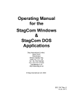
1.1 Cordless LAN
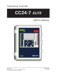
One of the most prominent applications of the DECT data link is a cordless local computer network
[Pah '95]. Figure 1 shows a typical structure of such network. One PC called the server PC manages
the cordless connections for portable PCs within its range. Via this PC a number of portable PCs can
get cordless access to a backbone network or request a link to another portable PC in the coverage
area (service area).
Portable PC
Figure 1: Typical structure of the DECT LAN
Examples of cordless LAN applications are:
• LAN for laptop computers: wireless connection is the natural medium for the personal portable
computing devices that are growing in popularity.
• Ad hoc networking: a group of portable users, for example in a classroom or meeting, intend to
set up a network among themselves in an unpredicted situation.
• LAN extension: extension of the wired LAN to areas with wiring difficulties like buildings with
large open areas such as manufacturing floors, stock exchange halls, warehouses, historical
buildings where drilling holes for wiring is prohibited, small offices where maintenance of a wired
LAN is not economically attractive.
1.2 Problem definition
The original project goal according to our coaches was: "Study of the feasibility and realisation of a
demonstratable high speed wireless data link according to ETSI standards using the Philips DECT
chipset, particularly the DECT Burst Mode Controller (BMC) PCD 5040". This meant a prototype
PC-card had to be designed that realises a high-speed datalink with use of the BMC.
During the project the specified goal has been translated into the following "project-steps":
1. Study of the DECT standard in relation with cordless data links.
2. Study of the possibilities of the BMC to implement a DECT data link.
9
3. Realisation of a low speed RS232 data link by reprogramming an existing Philips demoboard for
cordless telephony (warming-up project).
4. Design and realisation of a suitable hardware interface between the PC and the BMC to utilise the
full capabilities of the current Philips DECT chipset.
5. Design and implementation of control software for the realised interface.
6. Implementation of PC demonstration software.
Step 1 to 3 have the purpose of giving more insight in the matter connected to our problem, while step
4 to 6 are concerned with the realisation of the high-speed data link itself. The RS232 data link that
has been realised during step 3 is described in appendix C. This link is very useful for applications
where no high speeds are demanded.
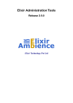
The prototype PC-card that has been designed during step 4 is called the DECT Data Controller
(DDC). This card is later on to be shown to customers. The DDC has the objective of taking care of
all the time-critical operations that are needed for a DECT datalink.
~
Portable PC
.-----.
.
..••••••••••.••••.•
:~
.....----. ' (
Serv or PC
~
portable PC
Figure 2: Functionality of the DECT Data Controller (DDC)
In practice step 4 appeared to be the most time-demanding rart of the graduation project. In Figure 2
a simple functional description of the DDC is given. Important design considerations for the DOC
are: the PC interface, computing power, bufferspace and communication with the BMC.
1.3 Structure of this report
To make this report readable for a diverse audience the chapters two to four describe the design
process for the DDC in an increasing amount of detail.
Chapter 2: Specifications
Describes the desired functionality of the DDC from different points of view: the DECT standard, the
BMC and the PC.
Chapter 3: Technical design
In this chapter the design process is described in an abstract way.
Chapter 4: Implementation
Here some parts of the design that are important for people that continue with the DECT data project
are worked out in detail.
After this in chapter 5 to 7 the current results of the DECT Data project will be discussed. The
appendices discuss all subjects that are not directly related to the design of the DDC. In a few lines the
appendices have the following subjects:
Appendix A: Overview of the DECT standard
10
In this appendix the layered structure of DECT is worked out. For understanding this report no
detailed knowledge about DECT is necessary.
Appendix B: User manual
This appendix describes the DDC from the point of view of a PC programmer.
Appendix C: Cordless RS232 pipe
Here the warming-up project is described. The data link that is realised here is very useful for
applications that do not demand high datarates.
Appendix D: Circuit Diagram
The circuit diagram of the DOC designed in Mentor Design Architecture V8 is given here.
11
2. Specifications
In this chapter the desired "black-box" functionality of the DOC is discussed. This is done from three
points of view: the BMC, the DECT standard and the PC. In chapter 3 the DDC will be worked out
according to the specifications stated here.
2.1 DECT Data standard
As stated in appendix B a DECT basestation can support a maximum of 24 physical channels
corresponding with the 24 slots per frame. These physical channels can provide so called bearer
services, the building blocks for connections. For example: a speech connection requires a duplex
bearer, which consists of two physical channels for sending and receiving speech.
For data connections DECT specifies the following bearers:
• Duplex or simplex bearers: Duplex bearers consist of two physical channels corresponding to two
slots exactly one half DECT frame apart and each working in the opposite direction. A simplex
bearer consists of just one slot.
• Connection-oriented or connection-less bearers: In case of a connection oriented bearer a each
physical connection has a fixed destination during the time a connection has been set up. In
connection-less mode a physical channel can have a different destination during each DECT frame
(packet oriented).
• Protected or unprotected bearers: Data protection is performed by CRC generation and
checking. When a corrupted frame is received it is discarded and retransmission is requested.
The current BMC can only provide unprotected,
been designed to support cordless telephones.
~onnection-oriented,
duplex bearers because it has
To provide high speed data connections DECT specifies multi-bearer connections. Here the current
BMC also has some restrictions, the BMC for the portable part only supports multi-bearer connections
up to a maximum of five duplex bearers (10 time-slots).
For a data connection protection is a necessary condition. The DDC should therefore contain a device
that can do this outside the BMC.
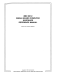
Figure 3 shows the DECT data structure for a protected, connection-oriented, duplex bearer. The two
slots that are used for the bearer are exactly one half frame apart. The six structures correspond with
the in and outputs of the DECT DLC, MAC and Physical Layer.
12
,
IiE
DLC
User
plane
t
. ..,
PDUO
U.o_M_-.1Ii1
I HIT I..<XI
+.+E--W-,....
MAC
PIlL
F"",d to Pcr1able Put
Portable to Fixed PlIrt
Figure 3: DECT multiplexing structure for a fuU duplex single bearer frame relay connection
A received slot will be checked by its CRC immediately after reception. When the received data
appears to be correct a piggy-backed acknowledgement is sent back in the ftrst sending slot one half
DECT frame later. The data sent over one duplex bearer can therefore never exhibit sequence
distortion. Data duplication however is possible because the acknowledgement of a previous slot can
get lost in transmission. This is solved by a modulo 2 sequence number as explained later.
When multi-bearer connections are used sequence distortion is possible while the capacity per bearer
can vary in time by RF transmission distortions. This is solved by adding a sequence number lP every
frame.
13
2.2 DECT Burst Mode Controller PCD5040
The BMC is a custom IC that performs most of the time-critical functions involved with a DECT
connection. The functional blocks of the BMC are shown in Figure 4.
PCD5040
Timing, Control,
Burst Mode
Controller
ToCODEC/
Highway
Data and control , r L - - I _............
for radio
8051/68000
Interface
Clod< Generation
Speech
Interface
RF Interface
Microcontroller
Interface
Figure 4: Block diagram PCDS040 DECT Burst Mode Controller
The basic philosophy around the BMC implementation is to have a few dedicated hardware blocks
containing logic for time critical functions with bit or byte accuracy. All other functions, with slot
accuracy, are contained in a small programmable RISC core: the Programmable Communication
Controller (pCC). This is done to offer maximum flexibility during prototyping.
The program which is executed by the FCC is called firmware. The fIrmware for a DECT portable
part and fixed part is not the same.
The microcontroller interface provides full access to the data memory. Via the datamemory an
external microcontroller can communicate with the FCC. The data structure inside this memory is
defined by the fIrmware [phil '94].
The BMC has been designed for cordless telephony. A cordless telephone needs two speech
connections in two directions, therefore duplex bearers are supported. Furthermore the datarate of the
speech connection is fixed, so a connection-oriented bearer is more efficient than a connection-less
bearer.
In worst case situation (during a handover of bearers) a cordless telephone demands fIve bearers. This
is why the BMC for the portable part only supports a maximum of fIve duplex bearers. Furthermore
the BMC does not support protected data transmission , because error correction by retransmission
would result in too much delay.
14
2.3 ThePC
The connection of the DECT data link with a PC is not specified by the DECT standard, so here some
creative input is still possible. For the PC the following parts of the design are important:
1. Definition of a communication protocol between PC and DDC for control and data mov~ment
2. Choice of a hardware interface that can realise the datarate required by the DOC.
Several solutions for these items are possible.
In this chapter these design areas will be worked out by giving some desirable properties the DOC
should have.
2.3.1 Applications
Today most modem PC-applications work in a multi-tasking environment like windows. In windows
this means that all active applications can use the processor in case of the occurrence of a specific
event. The DOC therefore must have the ability to support this kind of event-driven structure. In
practice this means the communication between PC and DDC works with interrupt-controlled
messages.
This event-driven structure will usually result in some delay between the occurrence of an event and
the start of the appropriate event handling procedure. The information that accompanies a certain
event therefore has to be buffered. Furthermore the dataflow has to be buffered because the DECT
datapipe works more efficient when a continuous flow of data is offered. This buffering will inevitably
lead to some delay in the dataconnection. Figure 5 gives a relative comparison of some applications in
respect to the maximum allowed delay and required data capacity.
Delay
x File-transfer
x E-mail
~Pl""ity
x Chat
x Multi-media
Data capacity ~
Figure 5: Overview of demands for some well-known applications
Another consequence of an environment where multiple applications can run simultaneously is that
more than one connection to different destinations can be needed. For example an agent of a
telemarketing firm could be using a database-server to look up telephone numbers of customers that
he wants to send a fax via a fax-server somewhere else in the network. He even could be chatting with
another agent to ask a question about a certain customer at the same time.
15
The realisation of multiple connections to different destinations with DECT appeared to be less trivial
as one would expect, because the capacity of every connection varies in time by unpredictable errors in
the RF path. In chapter 3 some possible solutions for this problem are given.
2.3.2 PC-interface
For the hardware interface between PC and DDC the following four options have been considered. In
this paragraph the advantages and disadvantages will be discussed. Ultimately these will be compared
and a interface will be chosen.
Option 1: RS232
The RS232 port is available at desktop and notebook computers. An advantage of this option is the
fact that control of the RS232 port is very simple. No special API for windows has to be written while
standard controls are available.
However the speed of the current RS232 ports is too low to fully utilise the capacity delivered by
DECT (approximately 534 kbps) and the processing power of current PCs.
Option 2: ISA bus
The ISA bus is very fast and flexible, but not appropriate for notebook computers. The server PC
however typically is a desktop computer because it is mostly connected to some ftxed backbone
network. The ISA bus solution could therefore be an option for this part of the cordless LAN.
Option 3: PCMCIA bus
The PC card standard of the Personal Computer Memory Card International Association (PCMCIA)
was originally deftned for memory expansion of laptop computers. The PCMCIA port is the obvious
choice for laptop computer extensions because it is flexible and fast. Furthermore it results in the most
elegant implementation since the PCMCIA port is designed for hardware that is integrated in the
computer housing itself.
However the PCMCIA bus is not standard available on desktop computer. Adapters to solve this are
recently available, but there is no information about the required control software.
Another disadvantage of this option is the high complexity. The PCMCIA communication protocol is
designed to make things easy for the user ("plug and play''), but not for easy implementations.
Furthermore the literature about the hardware interface and control software appeared to be not really
accessible.
Option 4: Parallel port
The parallel Centronix port is supported by both laptop and desktop computers. Furthermore it is easy
controllable by software. The maximum datarate of this port is lower than that of the PCMCIA or ISA
bus because the Centronix port just supports eight parallel outputs and even as little as four parallel
inputs. However most modern 386 and 486 type PCs support a bit rate of over I Mbps and because
DECT speciftes a maximum capacity which is less than 1 Mbps (when one basestation is used) this
should be enough.
16
Eventually the Centronix port (option 4) has been chosen. This is done to be able to use the same
hardware for the portable PCs as well as the server PC while keeping the complexity as low as
possible. When DECT Data would become a big market then there are a lot of advantages to keep the
hardware for fixed and portable part the same. Reasons for this are for example:
• Lower manufacturing costs
• Easier maintenance of wireless network (when a fixed part breaks down the DECT cell can easily
be repaired by a portable part with another EPROM)
2.4 Conclusion
The DOC that will be realised can not make total use of the DECT capabilities, because the current
BMC is in fact designed to support speech connections. This means the portable part BMC only
supports five unprotected, connection-oriented, duplex bearers. The fIXed part BMC however can
support a total of twelve duplex bearers (all slots in the DECT frame). This means the DOC has to be
fast enough to send and receive the data from all of these bearers.
Furthermore the DDC will be connected to the PC by the Centronix port to keep the hardware for
portable and server PC the same. This results in a decrease in implementation time and costs.
Furthermore maintenance of a cordless LAN is easier when all DOCs are interchangeable.
17
3. Technical design
This chapter describes the design process for the DOC solution from an abstract level. To do this an
object-model that describes distinguishable parts of the design-process is introduced. Each part is later
described in more detail. At the end of the chapter the designed machine in total will be discussed.
3.1 Design partition
Figure 6 shows the functional blocks that are used to realise the DECT data link.
Figure 6: Partition in design areas
A PC that wants to send data, requests the Manager block for a connection with a specific capacity to
a specific PC. The Manager then determines if enough capacity is available and notifies the specified
receiver PC.
When a connection has been established the sending PC writes databytes to the send FIFO in bursts.
This data is sent to the receiving PC by the Datapump blocks according to the DECT structure. At the
other end of the link the receiving PC is notified if valid data is available.
The connection is ended when the sending or receiving PC indicates to the Manager that one of them
wants to disconnect
18
3.2 ThePC
The PC object will be discussed in two layers:
1. PC software layer: instructions and processes that are needed to control the DDC
2. PC interface: The communication-protocols over the Centronix port.
3.2.1 Driver software for the PC
The PC software which controls the DDC has to perform the following three tasks:
• Managing the DDC
• Sending data to the DDC
• Receiving data from the DDC
As stated earlier the communication with the DDC occurs via the Centronix port. In this chapter only
a functional description of the desired functionality of PC driver software is given. The actual
communication protocol over the Centronix port is discussed in the next paragraph.
Management
In order to be able to set up a connection to a portable computer the server PC has to have a list of all
the active computers in its reach. The portable computer also has to notify the computer when it is
ready to receive calls or not
When the portable computer itself wants to communicate with another computer)t has to set up a
connection and release it when it is ready. This method corresponds with the connection oriented
connections the BMC supports.
The minimum set of functions for managing the data link for a portable PC are realised by the
following function calls:
• AITACH (J..PPIdentifier): Adds the identity of the computer to the list of active portables in the
server PC.
• CONNECT (J..ConNr. J..Bearers. J..DestinationId. J..Protected): Requests the DOC for a connectionoriented link of a specified number of bearers for the specified unique connection number to the
destination PC.
• DISCONNECT (J..ConNr): Notify the DDC that the connection should be ended.
The server PC does not need the ATTACH-call but must be able to read the list of active portable
computers in reach of the DDC. The rest is the same as the portable case:
• PPLIST (iNumOfPPs. jpPIdentifier[l..NumOfPPs)): Gives the list of active portables within
reach of the server DOC.
• CONNECT (J..ConNr. J..Slots. J..DestinationId. J..Protected): As portable computer.
• DISCONNECT (J..ConNr): As portable computer.
The DDC can generate the following messages:
• ACK_AITACH 0: The portable PC has been successfully attached to a server PC.
• NACK_AITACH 0: No attachment to a server PC could be made.
• INCOMING (J..ConNr. J..Bearers. J..DestinationId. J..Protected): Another PC is trying to set up a
connection. The PC should react with a CONNECT call.
• ACK_CONNECT (J..ConNr): The requested connection is set up.
• NACK_CONNECT (J..ConNr): The requested connection has not been set up.
• ACK_DISCONNECT (J..ConNr): The connection has been ended. No new incoming data has to be
expected for this connection number.
19
Sending data
The BMC sends data in indivisible 40 byte slots. The DDC translates this into protected 32 byte
frames, which can be used freely by the PC, the other 8 bytes are used for protection. The DOC
demands that data from the PC is send in 32 byte blocks.
Because the number of bytes that are send by the PC generally won't be divisible by 32 the sending
PC has to inform the receiving PC about the number of valid bytes per frame. This is done by a length
indicator (LI). Furthermore one bit called the "more"-bit (M) is send to indicate that more data will
follow after the current block.
When more than one bearer is used to transmit data of one connection the datablocks may be received
out of sequence. To restore the sequence in the receiving PC a send-sequence number (SSN) is added
to every datablock.
Like stated earlier a PC may receive data from several sources. Datablocks from a certain source are
distinguished by the Connection Number (CN). This number has to be unique within the sending and
the receiving PC. The Connection Number therefore has to be determined after a negotiation between
the two communicating PCs.
Figure 7 shows the structure of each datablock that is sent by the PC. Three bytes per block are used
for control leaving 29 bytes for data
Byte 1:
Byte 2:
I
~
0
LI,...
SSN6..o
Byte 3:
8TI
Byte 4:
I
0,...
1'--
0,_._
..
Byte 32:
1
CN"..
1
1
_
Figure 7: DDC datablock
The write-process of the PC is controlled by interrupts to support the event-driven structure of a
windows-environment. The DDC can generate three events: a SF_EMPTY-event, a SF_FULL-event
and a SF_HALFFULL-event. These events are all associated with the state of the send-FIFO (SF).
When the number of bytes in the send-FIFO slips below a certain level the DOC generates one
SF_HALFEMPTY-event. This event has to result in the start-up of the send-process. The SF_FULLevent stops the process.
An SF_EMPTY-event occurs when the PC does not react quick enough to the SF_HALFEMPTYevent. Usually this is caused by other processes that require a lot of computing-time. The occurrence
of a SF_EMPTY-event means that the send FIFO does not contain any whole frames anymore and the
DDC starts sending dummy-frames. When the SF_EMPTY-event occurs often at the sending and
receiving PC the capacity of the wireless connection should be decreased to increase spectral
efficiency.
20
......
......
-~--------------------------j------~-----------......
......
......
......
-------- ------------~-:-: -'1" --,-- --------- ---}
~~
BuffcDpal:o r..
_4~
SP..EMl'l'y
Figure 8: Interrupt controlled datamovement
Receiving data
The main difference between sending and receiving datablocks from the DOC is the fact that blocks
can be received out of order. This effect only occurs when protected multi-bearer connections are
used. Unpredictable retransmissions result in a time-varying capacity per bearer. The receive-process
of the PC therefore must have some kind of sequencing algorithm.
128'19bytelc:ycllc bulf..
§_LPO------.
i
I
N«,.._
~
L.:
~LRP -----.j
~~.~~~
NOfrecdwd
.J
;
I
LFO =Lut Franc m Older
LRF= Last Received Famo
Figure 9: Sequencing algorithm
The sequencing algorithm stores every received byte in a cyclic buffer at an address defined by its
SSN. The first received frame is send to the outputfile and after that every received frame that has a
SSN that is one higher (modulo 128) is send to the outputfile.
Because the DECT standard prescribes that the delay by retransmission of a frame may not longer
than 128 frames (the maximum number of frames that can be distinguished by the 7 bit send-sequence
number) a 128 frames buffer is enough for the sequence algorithm.
21
3.2.2 PC-interface
As stated earlier the PC will communicate with the DDC via the parallel Centronix port While the
Centronix port is in fact designed for communication with a printer some new protocol has to be
designed. This protocol must have the following properties:
• Minimum overhead over the parallel port: the parallel port is fast enough for DECT (> 1 Mbit/sec)
but every second the PC needs to pump data over the parallel port keeps it from doing something
else in the multitasking environment.
• Bi-directional communication: the Centronix port is designed for mainly unidirectional
communication with a printer. Hereby it has eleven outputlines and only five inputlines.
• Interrupt generation for event-driven control. Because the PC runs in a multitasking environment
the DDC has to indicate when the PC has to allocate processing power to communication with the
DDC.
To minimise the datarate over the parallel port the protocol has to minimise the amount of control
information that is needed for the communication. Redundant information is for example the
sequence in which bytes are sent within a frame. To remove this the protocol distinguishes between
plain data and control information.
As shown in Figure 8 the event driven structure of the read and write processes in the PC are
supported by interrupts that are related to the FIFO status. Furthermore the manager on the DOC can
generate all kind of control messages which result in events too.
Control of the DOC by the PC also works with messages. When a message is send by the PC the
management part of the DDC has to be notified by an interrupt.
The function of the desired protocol chip is shown in Figure 10. Four main communication functions
can be distinguished:
1. Sending and receiving data (communication with FIFOs)
2. Sending and receiving messages (mailbox communication)
3. Sending and m.eiving extra message information (memory mapped access)
4. Generation of events
Figure 10: Function of PC-interface
The protocol chip manages the communication between the PC and the Manager or the Datapump. It
is also connected to three independent units. The protocol chip reacts on certain actions that are done
by one of the units. Figure 11 shows the actions that are expected from the protocol chip. Because all
communicating units work independently it has to be taken into account that two or three actions
could occur at the same time.
22
WRITB_TOJ'lR)
READ_PROMJ'D'O
SPBCIFY...ADDRESS
PC
~~======
::::
WRITB.-TO...ADDRESS
READYROMj.DDRBSS
WRITE_MESSAGB
READJofilSSAGB
ACl10NS
MANAGBR
_=======
_
SOFT_RESET
WRITE....MBSSAGB
READ_MESSAGB
Figure 11: Possible actions on interface chip
The communication between the PC and the DDC works byte-oriented. Receiving a byte from the
DDC is done in two steps (nibble oriented), because the Centronix port only has four inputlines for
data (one inputline is needed for the detection of interrupts by the PC).
The DDC contains three event generating sources:
1. The send-FIFO: This can generate one of the following events: SF_FULL, SF_HALFEMP1Y or
SF_EMPTY.
2. The receive-FIFO: The events this source can generate are: RF_FULL, RF_HALFFULL or
RF_EMPTY.
3. The Manager: By an 8 bit message this source can generate 256 distinguishable events.
The occurrence of an event results in an interrupt to the PC. Since all of the sources can generate
events independently the PC checks all of the sources. While the events of the FIFOs can be
represented by two bits each the PC also has to read 12 bits in three steps.
The PC can initiate one of the PC actions by setting four control bits: PROTl, PROn, NWR and
NRD (see also appendix B). The protocol chip then gives information or waits for data from the PC.
The Manager and Datapump each initiate an action by dedicated inputs at the protocol chip. A small
description of every action is as follows:
PC actions:
•
•
•
•
•
•
•
WRITE_TO_FIFO: One byte of data is moved from the Centronix port of the PC to the sendFIFO.
READ_FROM_FIFO: One nibble (four bits) of data is moved from the receive-FIFO to the
Centronix port.
SPECIFY_ADDRESS: The PC specifies a 10 bit address that is used by the
WRITE_TO_ADDRESS andREAD_FROM_ADDRESS action.
WRITE_TO_ADDRESS: One byte of data is moved from the Centronix port to a specified address
in the Manager communication RAM.
READ_FROM_ADDRESS: One nibble of data is moved from a specified address in the Manager
communication RAM to the Centronix port.
WRITE_MESSAGE: One byte is written in the Manager mailbox, resulting in an Manager
interrupt.
READ_MESSAGE: The event identifiers of the three event sources are moved to the Centronix
port.
23
Manager actions:
•
•
WRITE_MESSAGE: The manager writes a one byte event identifier in the PC mailbox.
READ_MESSAGE: The Manager reads one byte from the Manager mailbox. The protocol chip
now accepts new messages from the PC (message serialisation).
Datapump actions:
•
•
VALIDATE_FRAME: The datapump has moved a new frame in the receive-FIFO and CRC
checking showed is was valid. By initiating this action the PC is now able to read the frame.
READ_FRAME: The datapump has sent a frame. The send-FIFO length is now decreased by one
framelength.
24
3.3 The DECT Burst Mode Controller
The time critical functions of the DECT physical and MAC layer are done by the a Philips PCD5040
DECT Burst Mode Controller (BMC). Originally this custom IC was designed to be used for DECT
speech communication. To create a good design for datacommunication the interfaces of the BMC to
the outside world have to be well examined. This paragraph gives a short introduction to these
interfaces and describes the impact on the design.
The BMC should interact with three objects: the DECT radio, the datapumps and the manager, see
Figure 6. The DECT radio is already evaluated and implemented by Philips. For more information
about Philips DECT radio see its manual.
Communication with the manager can only be done via the microcontroller interface of the BMC.
Requests of the manager, like a connection set-up request, can be sent to the BMC by placing the
message attributes in special registers of the BMC. If the request can be executed it will be confirmed
by the BMC else the request will time-out within a specified time. After this confirm or time-out
period the manager can place a new request. The BMC can also accept certain messages (commands)
that need not to be confirmed.
Data coming from the datapump can be placed into 'outbound' buffers in the BMC. The BMC will
serially send this data to the DECT radio. The incoming serial data from the DECT radio is placed
into 'inbound' buffers and can be retrieved by the datapump. There are two ways to access the BMC
for this data transfer:
• By means of a serial interface
• By means of the microcontroller interface
The choice between these interfaces has a large impact on the design because these interfaces are
totally different. Therefore a comparison is made between these interface:
low
high
30msec
max. 64 kbit/s
high
high
lOmsec
max. 160 kbit/s
The serial interface makes the design more time-critical, because data should be placed and retrieved
bit synchronous. Special hardware should be designed to execute this task. This interface is also less
suitable for data communication because it has been designed for the transfer of speech, which is more
error tolerant. According to the DECT ABI profile [ETS '94] for protected data communication
erroneous data frames should be retransmitted. Using the serial interface of the BMC would result in
delays of tens of microseconds. Using the microcontroller interface has the advantage of less delay,
important for real-time applications. Because this interface is 8-bit wide and directly connected to the
inbound and outbound buffers resulting in more flexibility and possibly a higher capacity (5 instead of
2 channels available). An disadvantage of using the microcontroller interface for datatransfer is that
this interface should be shared with the manager.
25
.---
---. switch control
------.
I
Manager
I
I
I
I
radio interface
: pC interfac
I
~---,/---l
BMC
serial interface
Datapumps
synchronisation
Figure 12: Sharing of the BMC microcontroller interface
A fast programmable controller connected to the microcontroller interface and having the right
information for synchronisation to the BMC seems to be a good implementation for the datapumps. If
the DECT ABI profile should be fully implemented at a later phase, software can be changed simply.
The interface can be shared with the manager by using a switch, see figure 12.
The state of the switch is controlled by the manager. Negotiation about the access to the pC interface
of the BMC can be done dynamically between the manager and the datapumps by means of messages
if necessary. However it will be shown that the datapump needs the pC interface at predefined periods
of time. The next chapter will defme these periods.
26
3.4 The datapumps
The datapumps main objective is to move (pump) frames of data from the send FIFO to the outbound
buffers of the BMC and to move frames of data from the inbound buffer of the BMC to the receive
FIFO.
In the figure below these two processes are called 'data send' and 'data receive'. The dashed lines
represent control information [Sys '94]. The strllight lines represent a flow of data.
. .-:::::.. ---.. --_·_···_····_··-S
Slot transition
Send FIFO full
Figure 13: Datapump context model
Other objectives are:
• synchronisation with the BMC
• flow control
• detection of erroneous received data and correction of these errors
The datapumps should operate synchronously with the BMC. If for example the BMC has sent an
outbound buffer to the radio the datapump should move a new frame from the send FIFO to that
outbound buffer. Furthermore if the receive FIFO is full the terminal at the other side should be
stopped to transmit a new frame. Received data should be checked upon errors. This is done by
insertion of cyclic redundancy check codes. If an error is detected in a certain frame, this frame should
be retransmitted. Aspects about flow control and error correction by means of retransmission are
described in paragraph 3.4.2. Paragraph 3.4.3 describes the design aspects for multi-bearer
connections. Error detection is explained in paragraph 3.4.4. The next paragraph describes the
necessity of synchronisation to the BMC.
27
3.4.1 Synchronisation with the BMC
After the manager has established a cordless connection with another PC, the data transfer phase can
be started and the datapumps should be activated. Suppose the manager has established one full
duplex traffic bearer, see figure 3, to another PC. Moving a frame of the send FIFO in the correct
outbound buffer of the BMC will lead to a transmission of this data frame. However the datapump
cannot do this at an arbitrarily moment because the BMC reads the outbound buffer at a specific time.
The data receive and send processes have to be synchronised to the BMC so that they start moving
data at the right moment.
For the data send process the following timing constraint should hold:
The frame in the send FIFO should be nwved into the outbound buffer before the BMC will transmit
the contents ofthe outbound buffer.
For the receive process can also a timing restriction be derived. In every DECT frame the BMC writes
the received frame (that was sent by the other PC) in the inbound speech buffer. So in order to
maintain data consistency the following timing constraint should hold for the data receive process:
A frame in the inbound buffer of the BMC should be nwved into the receive FIFO after the BMC has
updated the contents of the inbound buffer.
Another timing constraint can be derived from the flow and retransmission protocol.
3.4.2 Flow control and error correction by means of retransmission
For flow control and error correction a well known protocol is used: the alternating bit protocol. This
protocol is well suited for DECT because after each transmission there is exactly one reception (after
5 msec) and the other way around
If a received frame is erroneous, a retransmission of this frame should be requested to the other side.
This is done by a special acknowledge bit, named ACK. The frames are numbered alternating by
means of the control bit FN, so a retransmitted frame has the same number as the last transmitted
frame. Figure 14 shows the alternating bit protocol and flow control protocol, which is executed by
the datapump of PCI and PC2. The combination of data with control is done in both directions. This
is called piggybacking.
28
The decision to update the outbound buffer can be made until the ACK bit has been received. This
yields the following timing restriction for the send process:
Aframe in the send FIFO can be moved to the outbound buffer after the reception ofthe ACK bit.
If the ACK bit is detected to be corrupt by the CRC checker the sending side should consider this fact
as a not acknowledge and retransmit the same frame.
Because the CRC is generated over the data and the control bits ACK and FN. the data frame should
be moved out of the inbound buffer so that it can be established that the ACK bit and FN bits were
correct. If it should be moved out of the inbound buffer anyway it can just as well be moved to the
receive FIFO.
Combining this and the three defined timing restrictions results in the following event-response table
for the data transfer process:
29
.Kninl :.,
.
...
.'
. : . .
..
R'espoose"
.. '.
:
:.
.
.
.
:. R'esm.mst! time
.
! 763 Jls
.................................................................................................~~.P...~~}.~ ..~¥~
.\.
RACK=1
SFN=! previous SFN .
~ 763 Jls
move frame from send FIFO to BMC
!
··SACi{;o:············································································T·763··ps···············
RACK=O
SFN= previous SFN,
··CRC~ER:ROR··············································
..f:!".~~.~gY.~~.f:!"g~ ..~~~~.!:!!':Q ..~.~.~~
RFN== previous RFN
SFN=previous SFN, keep frame in BMC
!
~~=~~
L.I~~.p.~
! 763 Jls
FRAME_VALID,
SACK=1
~
Note: RFN means 'received frame number' and SFN means 'send frame number'. RACK means
'received acknowledge' and SACK means 'send acknowledge'. So RFN is the SFN of the peer side
etc.
Note: the response times are calculated in the next paragraph.
The data transfer process should be activated as soon as the inbound buffer contains new and valid
data. This event should trigger the execution of the following statements:
• The frame in the outbound buffer should be moved to the receive FIFO.
• If the frame is erroneous a retransmission should be requested by means of clearing the SACK bit.
• If the frame was received correct the frame number bit RFN should be checked. If RFN equals the
previous RFN the previous acknowledge bit SACK was corrupted and the frame was already
accepted by the peer side.
• The acknowledge bit RACK should be checked. If RACK==O the frame should be left in the
outbound buffer of the BMC.
• If the frame was received correct at the other side (RACK==I) the datapump should move a new
frame from the send FIFO to the correct outbound buffer of the BMC.
Receive half frame
Transmit half frame
, . radio outbound data
8!
,3;;;;"
20
start data transfer
Figure 15: Relation with DECT TDMA·frame
The basic data transfer process should be started at slot transition 8 to 9 and should be carried out
before slot 20, see figure 15
30
.
.
.
Because the traffic bearer at the receiving half of a DECT frame can be allocated at slot 0 till 11 the
datapump should get all slot transition events for those slots.
Because one slot consist of a 40 bytes frame the maximum unidirectional throughput of a full duplex
single bearer connection is 320/10 msec = 32 kbit/s. If four 16 bit CRCs are added to a frame the
throughput will be (320-4*16) /10 msec = 25.6 kbit/s. The data link layer uses another 24 bits for its
control. This results in a maximum unidirectional throughput of (320-4*16-24) bits /10 msec = 23.2
kbit/s. If higher throughputs are required, multi-bearer connections have to be established.
3.4.3 Multi-bearer connections
If the manager has established a multi-bearer connection the datapump should handle a data transfer
process for each traffic bearer. This results in a more complex design.
Because there is only one FIFO where correct received frames will be placed sequence distortion can
occur due to the retransmission protocol. This sequence must be recovered by the data link layer,
which should be implemented by PC software.
A data transfer process should be started after the slot transition of a each received traffic bearer as
soon as the previous data transfer processes have finished. The figure below shows the most timecritical situation, Le. 12 active traffic bearers:
Receive half frame
Transmit half frame
radio data in
radio data out
~--------------------~ . ~--------------------~
I
I
763 Jls
Figure 16: Multi-bearer structure
The data transfer process for traffic bearer 11 should have finished before slot 23. Therefore each
process should take less than 22/12 slot 763 psec .
=
The datapumps should be synchronised to the BMC by means of an external signal which indicates
each transition of a slot., see figure 13. This signal can be created out of the DCK and CLKl00
signals of the BMC.
The microcontroller that implements the datapump should be able to complete the each data transfer
process in 763 JIs. A Philips 80C51 microcontroller (running at 30 MHz) would easily satisfy this
constraint. However this microcontroller is not fast enough to do CRC checking and generation as
well. These routine tasks should be done by dedicated hardware which operates parallel to the
microcontroller.
31
3.4.4 Error detection and frame format
The cordless transmission of data through a non ideal communication channel causes errors which
should be detected and corrected. Error detection can be done by calculating cyclic redundancy codes
(CRC) and transmitting these codes together with the data. The CRC codes are defined by a
generator polynomial described in the DECT standard. A CRC generator and checker can be easily
implemented using simple shift registers with feedback connections. The data to be transmitted
should be shifted serially into these registers. If all data is shifted the contents of the shift registers
contain the CRC code. By transmitting the CRC together with the data the CRC checker at the other
side is able to detect (almost) any error. The used alternating bit protocol described in paragraph 3.4.2
relies heavily on this error detection. The following frame format is used for the alternating bit
protocol with error detection:
I<:
II
u
8
I
><:
SSN
8
BO
~64
INFO
lACK. FN, O. CNO•..• CN41
><
8
><
Bl
B2
I
64
64
)(
I
B3
)(
64
RB2-CRC
16
I
RB3·CRC
)<:
I
16-;"
Figure 17: Frame format
This frame format is almost compliant to the DECT standard for dataeommunication, see paragraph
2.1. The 16 bit CRCs for each B-subfield are calculated by the CRC generator which operates parallel
with the data send process, see figure 13. The SACK and SFN bits are inserted in the BO subfield. At
the peer side the RACK and RFN bits and the higher layer data (LI, SSN, CNO..CN4 and INFO) are
checked for errors by the CRC checker which operates parallel with the data receive process. The
CRC processor, Le. the CRC checker and generator, is working as a coprocessor and will be
implemented as dedicated hardware.
32
3.4.5 The problem of multiple connections
In Figure 18 the case of multiple portable computers sending data to one server is shown. In this case
adding a connection number to each OLe frame will be sufficient to support multiple connections.
The OLC frames for every connection are sent to just one destination.
Figure 18: Multiple outgoing connections
In Figure 19 a case is shown where one PC sends OLC frames to different destinations. In this case
some problems occur while the BMC only supports connection oriented bearers. This means each
connection needs his own (set of) bearers. While unpredictable frame errors result in an unpredictable
decrease of capacity per bearer the capacity per connection will now vary in time. This effect results in
an unpredictable sequence of sent OLC-frames and therefore buffering of these frames in the DOC is
not possible anymore.
CN,
.f1
(~
eN,
_
... PC
r8
(r
eN
,
eN,
~
....orPC
_bkPC
Figure 19: Multiple incoming connections
Figure 20 shows that the problem of varying connection capacities is not restricted to the server PC.
The possibility for the portable PC to set up connections to other portable PCs in the OECT cell
directly results in the same problem of sending OLC frames with different destinations.
33
eN,
eN.
T
DDC
Figure 20: Multiple internal connections (within one DECT cell)
This problem can be solved by one of the following solutions:
Solution 1: Change the BMC firmware to support connection-less bearers.
This is the most efficient solution. because when the real-time capacity of a certain connection drops
in comparison to another connection temporarily more bearers can be provided for this connection.
However changing the firmware is a time-demanding job that can only be done by experts.
Solution 2: Enforce equal connection-capacity
This is the simplest solution when the firmware is regarded fixed. When the capacity of a certain
connection drops the capacity of all of the connections is limited to keep all connections the same. Of
course this will result in a over-all decrease of capacity and spectral efficiency.
Solution 3: Software feedback from DDC
Here the DDC does not buffer frames anymore. The PC just sends one frame of a specified connection
when the DDC requests it. This solution results in a lot of overhead, but the over-all capacity of the
data link does not drop.
In practice solution 2 is the simplest and best solution.
34
3.5 Management
The manager has the following objectives:
• initialisation of the DOC.
• communication to the BMC
• synchronisation to the server PC (base station)
• connection establishment
• activating and stopping the datapumps
• connection release
• translation of DOC requests/commands to BMC requests/commands
• transmission error handling: releasing erroneous traffic beaerers and establishing new traffic
bearers
The manager will be implemented by software running on a Philips 8OC51 microcontroller for the
following reasons:
• The BMC can only be controlled through the microcontroller interface.
• Software running on a 80C51 controller for connection establishment, release etc. has already
been designed.
• Software running on a microcontroller can easily be changed.
• No glue logic is needed to connect an 8OC51 controller to the BMC.
• The DDC is a Philips product, so components and semiconductors of Philips are preferred to
used.
• Experience with 80C51 microcontrollers is already present.
re
To accomplish the objectives of the manager the controller should be able to communicate with the
PC and with the data transfer 80C51 microcontroller. These interprocessor communication paths can
be implemented using dual-ported RAMs with two so called 'mailboxes', one for each direction. If
one processor writes data in this mailbox the other processor gets an interrupt signal, which indicates
that a new message was received. The processor can read and identify this message, which results in
an automatic clear of the interrupt. Using dual-ported RAMs increases flexibility in the software
design in multi-processor architectures.
35
3.6 Conclusion
If the PC has information to send to a certain destination it has to ask the manager to establish the
connection. As soon as the connection is confirmed the manager starts the datapumps. The alternating
bit protocol in co-operation with the CRC generator and checker takes care of errorless transmission
of data. Using the microcontroller interface of the BMC for the transfer of data results in a fast and
flexible data communication path. However the microcontroller interface should be shared with the
manager controller. Therefore a switch is necessary. The data transfer controller should be
synchronised with the BMC and have enough speed to execute a data transfer process in 763 ps. A
80C51 microcontroller running at 30 MHz is suited for this job. The multi-controller architecture
requires dual-ported RAMs with mailboxes, which increases flexibility in the software design. These
issues have resulted in the following hardware architecture for the DOC:
r--------------------------.
r-------------,
Mailbox
au Cam>I
•
•
r------~-----~~~IQ
I--_--'-I~
I
CRCJjRR
PCINT
aDP
REC.PIFO
.",....,"!
a
FRAMB-.8YNC :
SENDPIFO
At
...............
!
;
SLOT SYNC
3O:----EJ-Figure 21: Hardware layout for the DOC.
The DDC has to move frames to one certain destination. It is transparent for link-numbers, so in case
of multiple links to different destination time-multiplexing is necessary. Note that the reroute-function
of the fixed part is transparent for link-numbers.
Comparison of Figure 21 with Figure 39 shows the extra complexity that is needed for higher speeds.
When no high speed is required maybe the RS232 solution described in appendix D will be the best
choice.
36
4. Implementation
This chapter describes the implementation of the DDC hardware and software. The most significant
topics of the implementation of the DOC are:
• Memory mapping of the data transfer controller and the manager controller
• CRC processor
• Switch connected to the pC interface of the BMC
• PC interface
• Data transfer software
• Clock control circuit and reset circuits
These topics will be explained in the next paragraphs.
4.1 The data transfer software
The specifications of the data transfer software is described in paragraph 3.4. The event response table
and the alternating bit protocol scheme results in three flow charts which are fmally implemented in a
80C3l C programming language.
If a slot transition occurs the pC should vector to an interrupt routine and increase its internal
slotcounter modulo 24. If a receive traffic bearer is detected a flag transfer[bufnr] should be set. This
flag should activate the correct data transfer process in the main routine. For the fIXed part buffernr
equals slotcounter. For the portable part buffernr should be calculated from the RF slot control table
because there is no fixed relation between the buffer number and the RF slot number.
Figure 22: Flow diagram
38
The main routine should start with the initialisation of all global variables and the synchronisation of
its internal sloteounter to the BMC slotcounter, see figure 23. Also the contents of the outbound
buffers should be cleared. The manager controller can start the data transfer process by writing a
START/STOP message in a specific area in the inter controller communication RAM. A data transfer
process datatransfer(buffer) can only be started if the transfer flag transfer[buffer] is set. In this way
the data transfer processes are executed sequentially as described in figure 24. The number of
simultaneously active bearers in the portable part is limited to 5. So the constant MAX will be 5. For
the fixed part this value will be 12, since 12 simultaneous traffic bearers can exist.
Figure 23: Flow diagram
39
If the transfer flag is set by the slot transition process, the procedure datatransfer[buffer] will be
executed. The actual parameter buffer indicates the inbound and outbound buffer should be read and
written.
The data transfer procedure is straightforward translation of the event response table and the
alternating bit protocol described in paragraph 3.4. However some tricks have to be done in order to
protect the SACK and SFN bits against transmission errors. Furthermore the use of a pointer to the
send and receive FIFO is necessary. The variable errorcount[n] is located in the dual ported
interprocessor communication RAM. In this way the manager controller can detect a traffic bearer
with too many errors, release this bearer and establish another one.
no
Figure 24: Flow diagram
40
These flowcharts are just an indication of the instructions that should be executed by the 80C31
microcontroller. However for the determination of the total execution time of a data transfer process
the number of clock cycles of each 8OC31 instruction generated by the C compiler must be counted.
After optimising the C code and using a 30 MHz processor clock the execution time is approximately
350 JIseconds. Since this is less than the timing constraint of 763 JIseconds it is possible to use 12
active bearers simultaneously. The capacity of one protected traffic bearer is 23.2 kbit/s (see paragraph
3.4.2). The fIXed part is able to transmit and receive 12*23.2 kbit/s =278.4 kbit/s. Because of the
limitation of the firmware in the BMC the portable part can establish only 5 active traffic bearers
resulting in a capacity of 5*23.2 kbit/s = 116 kbit/s.
4.2 Clock and reset control
In order to relieve the real-time programmer from heavy timing constraints both microcontrollers
should run on a 30 MHz clock. The price for this is that the used RAMs and EPROMs should have
access times of 80 ns and lOOns. However the access time of the internal RAM of the BMC is to long
for a 8OC31 running at a 30 MHz clock. Therefore the clock of the 80C31 should be stopped
(stretched) every time the 80C31 wants to access the BMC data or program RAM. A 30 MHz
stretched clock signal can be generated by a negative edge triggered JK flip-flop toggling at a 60 MHz
clock:
CSN
RESET ...
---.
RDN
Clock /2 , stretched
WRN
RDYN ...
--1
Figure 25: External clock stretcbing
If J=1 and K=1 the Q output is toggled at every negative edge of the clock signal. The Q output is
cleared if J=O and K=l. The J input is connected to the following combinational logic:
J = CSN+RESET+ 'RDYN + RDN • WRN
In this way Q is cleared at a negative clock edge if there is no reset, a RDN or a WRN is low, if the
BMC RAM is selected and if RDYN is high. The Q output will toggle again at a negative clock edge
as soon as RDYN goes low again. RDYN is an output signal of the BMC and indicates when the data
is written in or read from the BMC RAM. This clock stretch will take less than 0.6 JIs.
.
Because the 80C31 microcontroller can only be reset if it has a valid clock the JK-flip-flop must be
reset before the reset of the microcontroller. This can be achieved with the following circuit. The RC
circuit takes care of the necessary delay (R*C = 1 msec).
41
JK-.NRESET
10k
I-or-----Dc- RESET
4k7
Figure 26: Reset circuit
4.3 Access to the microcontroller interface of the BMC
Both the data transfer microcontroller and the manager controller should have access to the
microcontroller interface of the BMC. This interface consist of an unidirectional address bus, a bidirectional multiplexed datal address bus and a unidirectional control bus. A switching circuit
controlled by the manager controller prevents bus conflicts:
INfN,RDYN
SIm_'IRANS
Figure 27: BMC interface
42
The BMC_BUS line of the manager controller controls the position of the switch. The unidirectional
address and control busses of the manager controller and the data transfer controller are switched by
means of a multiplexer: the 74HC157. The bi-directional address/data bus ADO..AD7 is switched by
means of two transceivers: the 74HC245. The direction of the transceiver is controlled by RDN. If
RON is low and if the BMC address space is selected and if the BMC_BUS control line has selected
the microcontroller data coming from the BMC is routed to the selected microcontroller. In case of a
write cycle the direction of the transceiver should not be changed.
4.4 The CRC processor
The CRC processor is based upon a generator polynomial defined by DECT [ETS '94]:
The CRC generator can be implemented by 16 shift register cells and 5 exclusive ORs:
RDN
A~M
RDN
Q
SfORE
SHIFf
D1..DO
Figure 28: DECT MAC R-CRC generator
The 8 bit wide data can be converted by a PISO, a logic device like the 74HC597, into a serial bit
stream. After shifting a complete B subfield (64 bits) into the shift registers the 16 bit CRC is
available at the outputs of the shift registers. The PISO is controlled by the CRC controller. The CRC
generator is 'listening' to the databus if the data transfer microcontroller is moving data from the send
FIFO to the data buffers in the BMC and if the CRC generator is enabled by G_NEN, which is an
output pin of the data transfer controller. The CRC controller retrieves its timing by the CLK, ALE,
RDN inputs.
The CRC checker basically has the same structure as the generator, see figure 29. The checker should
listen to the databus when the data transfer controller is writing a 64 bit B subfield into the receive
FIFO. The CRC checker can be disabled by T_NEN which is connected to an output pin of the data
transfer controller. After shifting a complete received B-subfield the CRC checker generates an error
43
pulse if one of the outputs of the shift registers has a high level. This error pulse is passed to the data
transfer controller which should ask the peer PC for a retransmission.
Figure 29: DECT MAC CRC checker
The CRC generator and checker is connected to the data transfer controller in the following way:
Q{C~OR
r---
data
transfer
controller
D-bus
D-bus
I
I
I
I
I
REC.FIFO
BMCINBOUND&
OUTBOUND BtJFFIlRS
I
___I
SEND FIFO
Figure 30: CRC interface
The state machines that implement the CRC controller for the generator (8-control) and checker
(t_control) are shown in Figure 31.
44
ll-conttol:
~-~--~
I----------.J
~
iDi1
midI
.....w ......
Figure 31: Statemacbines for control of CRC generation and checking
The CRC generator and checker are implemented in a VHDL like language, AHDL, which can be
compiled to special code that can be used to program an Altera EPLD.
45
4.5 Memory mapping
The manager controller and the data transfer controller have the following memory map:
FFFF
FFFF
Data transfer controller
general DATA memOty
(32 KBytes)
Manager controller
geneIll1 DATA memory
(32 KBytes)
8000
6000
4000
8000
Management RAM (1 KBytes)
6000
Interproeessor RAM (1 KBytes)
4000
3000
CRC (2 Bytes)
Interproeessor RAM (1 KBytes)
PC intenace (9 Bytes)
FIFO (4 KBytes)
2000
0000
BMCDATA (2KBytes)
0000
BMC DATA (2 KBytes)
Figure 32: Memory map
The BMC DATA memory is located at address OOOOH and the general DATA memory is located at
8000H. This is done because a former evaluation board of the BMC has the same location of these
RAMs. This makes the DDC code compatible to these boards.
Note: the BMC 4 Kbytes code RAM can be accessed by setting MEM_SEL (control line Cl[OD. In
this way the portable part or fixed part firmware can be downloaded.
46
4.6 Controlling the DDC
The DOC is controlled by two 18 bits wide busses connected to the manager controller and the data
transfer controller: Cl and C2. These busses are defined below:
Cl[O..17]:
o
l MEM SEL
·.·.·.·.·.·::.·:.·.i:::::::.·j·.·.·~§~~~:~~.!.·.·.·.~· :
3
4
...........?
...........~
7
8
i Select BMC PCC program RAM
PLO (0)
:.~ ·.·.·J.·.r~1~J~~t-~:.~·~~.·~==~·.~·.·.·.·.·.·.·.·.·.·.· ~ ·.·.~t~J~·: :.·: : : .~ ·.~·.~·.·.·.·.-.1
! Fast mute CODEC
Pl.3 (I/O)
PIA (0)
!
L.~.~
.L~~~ ..£!9.£~
~.~.:~.~Qll...~.~~
~!:.?..(9.L
..J
l
l BMC NINT
l Occurrence of BMC event
l EX I/O
i CODEC
PM
U~~.~A~~
l DDC external I/O
l..~~~.~5.~:. ~.f..~~1!~.~~.~~ ..!~~~~~~.~
! IIC data
j SDA
Pl.7 (0) / SDA
nINTO (I)
l
·.·.·.~·.·.·.·.·1Q:.·.·.·.·.·.·.·.·L·~~:~~.·.·.·.·.·.·
.·.·.·:.·.·.·.·.·.·.~·.·.·.·.·.·.·.·.·.·.·.l·.~ i ~;.~~~~i~:.r~~~~:.~·.·.·.·:::.·.·.·.·.·
~
. . ·T1.i1ilit.·~~~:::::::::::::::
. . .-J
11
i SLOTTRANS (DART eLK) l DECT slot transition
(I)
i
12
........ }~
......... .!~
15
16
..........!.?
! CRC
NERR (RxDl)
l..~~~
L.~~QM~"'~
i NWR
~ NRD
L.~.~!
! CRC not error indication
.1..~.~:?~.! ..~.~!~~~
RxD (I)
?Q:~! ..m
~~.!}~J9.L
nWR (0)
nRO (0)
1
LA~~~.~.~.!~~S.~.~~.l;l;~.~~
M:E:.(QL
.J
C2[O..17]:
o
...........~
...........?:
3
4
...........?
...........~
7
8
...........~
l CRC CLR
l..!"'~~
] 9."'~~
! CLKIOO
l FRAME NVAL
j ~=~~
l..~£=~~
i FRAME NRD
! CRC
NERR
1..~9..~=~~
CRC clear
~~~..£~.~~~~.~~.~.~.~~~!~
PLO (0)
~~:.~ ..(QL
~~~.g~~~~~~g~.~~..~~~~!~
DECT slot RCV/SND indication
Received frame is valid
~.~.:?:,(Q>.
Pl.3 (I)
PIA (0)
~~£~~!~.~!9..!~..f.1!!!
~.~.:?..
~~:.~ ..(9
~.~~.~.!~.f.<?.~.~.~p.~y.
m
Frame in send fifo is read
CRC not error indication
Pl.7 (0)
nINTO (I)
Q££~.~~.~.~f..P~~.~~} ..~!~~~
~~~T~..
..
.
.
.
m .
! ~.~Q~~
1 DART CLK
l FIFO NINTREQ (RxD2)
Qg~T.~.~~.~..~~.~!.~!~~
DART clock
PC interface message indication
:!'Q.m
11
12
16
! NRD
Data read
nRD (0)
..........~.T
l..~!}?:
A..~~~~~}~~£~ ..~~~~!~
~~.~Ql
..........!Q
~
.L~9.~ ..~9.~~.~~.~
! Data write
l Data read
.
Tl (I)
RxD a)
..
Both controllers have an DART interface (DART clock, RxD and TxD) which can be connected to a
terminal. The DART channels are used for testing the software of the DOC.
47
l
4.7 PC interface
The protocol chip which implements the communication protocol over the Centronix port has been
implemented by a EPLD of Altera The control of the logic inside this chip is done by two main state
machines: one for communication with the PC (Figure 33) and one for communication with the
datapump (Figure 35).
A - PC synchronisation
B - Action recognition
C - Action serialisation
c
Figure 33: Statemachine for communication with PC
When the PC state machine is in Idle stale it waits till the PC alters one of the control bitJ. When this
is done one clock later (to be sure the control information is stable) the state machine decides which
action is initiated. This is necessary because the PC is asynchronous to the protocol chip.
Actions that result in a read or write cycle on the Manager communication RAM or the FIFOs consist
of multiple states as shown by Figure 34.
48
READ-CYCLE:
i
NCB
NOB
DATA IN
ADDRB'lS
I
~ VALID ~
VALID
)
:-----{K\__ _.:--_----:._
_-Ir--~
srABLB
RO
R1
R2
WAif
WRITE-CYCLE:
NCB
i_----:-_----:-_--:--_I
ADDRB'lS
DATA OUT
~~~
+ID
)>-i- - - - !
:---~:------:-----iK\__ _V_:_~-ID---I)..:...- - - '
srABLB
wo
WI
W2
W3
WAif
Figure 34: Read and write cycles of the protocol chip
The following relation between actions and states exists:
• WRITE_TO_FIFO H wID, wfl, wf2, wf3
• READ_FROM_FIFO H rID, rfl, rf2
• SPECIFY_ADDRESS H spc_a
• WRITE_TO_ADDRESS H wsO, wsI, ws2, ws3
• READ_FROM_ADDRESS H rsO, rsI, rs2
• WRITE_MESSAGE H wiO, wil, wi2, wi3
• READ_MESSAGE H rfi, rmiO, rmil, rmi2
• SOFT_RESET H init
Mter the state machine has responded to a certain action the state machine waits till the PC is back in
idle mode, so every action results in just one reaction (action serialisation).
The Datapump state machine works in much the same way. The only difference is that in this case the
communication is synchronous, so no extra stable state is needed.
49
A - Instruction recognition
B - Instnlclion serialisation
Figure 35: Statemachine for communication with datapump
Relation between actions and states:
• VALIDATE_FRAME H val, inc_rf
• READ_FRAME H read, dec_sf
• INITIALISE_INTERFACE H r_ctrl, w_ctrl, wait
For detailed information about the protocol chip see the Altern code files.
50
5. Verification and results
The DDC hardware is implemented as an 6 layer PCB. It is fully tested and debugged by means of
designed test software and many measuring instruments like the Nohau 8051 Emulator and an
oscilloscope. Most design concepts could be easily implemented and worked well after eliminating
some minor, but hard to trace, bugs. Only three minor hardware (layout) errors have been detected
(and corrected) yet because much time was spent in the design phase.
The Centronix port is made bi-directional and with a bitrate of over 1 Mbit/s it is suited for DECT
applications. A proprietary protocol is defined for communication with the PC. A PC programmer can
transparently read and write data to the Centronix port by means of driver software for the Centronix
port.
The buffer size and thus the delay can be determined by means of programming the PC interface
EPLD via the data transfer controller. In this way multiple applications, such as chat and file transfer
are supported by the DDC.
After a few modifications the demonstration driver software (version 5.8) of a former DECT
evaluation board can be executed by the manager controller. This software together with the BMC is
the implementation of some important DECT specific services such as synchronisation, traffic bearer
establishment, encryption, RSSI scanning and bearer handover.
By adding a ADPCM CODEC IC to the DDC it is also possible to transmit and receive real-time
speech. This service has already been implemented (the BMC is designed for this service) but the
combination of speech and data can create new applications.
The data that is received in the PC is almost free from transmission errors by means of CRC error
detection and a retransmission protocol at the MAC layer. Also the PC is protected against loss of
data due to buffer overflow by means of a flow control protocol. Duplication of data and sequence
distortion is eliminated by numbering each data frame.
The communication software of the data transfer controller is able to read and write 12 traffic bearers
within one DECT frame of 10 msec. However the portable part firmware of the BMC supports only up
to 5 duplex traffic bearers. An effective throughput of 23.2 kbit/s can be achieved for each traffic
bearer. Using five buffers this would result in a maximum throughput of 116 kbit/s, enough for most
cordless PC applications.
52
6. Conclusions
The designed and realised DOC can be used for the creation of a cordless PC LAN. The interfaces to
the PC and BMC and the DECT standard are fully examined. The DOC is optimised for
communication through these interfaces and is still very flexible for future changes by means of two
programmable controllers.
It is proven that the BMC can be used for cordless data applications. However the BMC cannot
support the full DECT AB1 profile [ETS '94].
To fully implement the DECT AB1 profile the following changes of the BMC (fIrmware) are
necessary:
• Support of 23 simplex MAC bearers in one direction (TIf service): the current BMC only supports
duplex bearers. This means the wireless connections will not be used efficiently while
dataconnections are generally not symmetric.
• Connectionless bearers (optional): by this the problem of multiple connections will be solved.
• Normal set-up procedure for multi-bearer connections instead of basic set-up procedure.
• Support of GF , Ip and Bs channels at the MAC layer.
• Frame relay service at DLC layer (LU2 Class 1 service): only error detection at DLC layer.
• FU6a and FU6b frame format at DLC layer.
According to [ETS '94] there are no requirements for the Network layer and the DLC control plane.
Furthermore some extra changes in the BMC fIrmware or hardware will minimise the required
hardware for the DDC:
• Generation and checking of CRC: a CRC processor will not be necessary anymore.
• Generation of an extra interrupt at the beginning of a DECT slot in use.
The power consumption of the DOC in full operation is approximately 800 rnA x 5V= 4 Watt A
portable PC can hardly supply this power from its own battery. Reducing the power consumption can
be done by implementing a power down function and the integration of the CRC functionality in the
BMC.
By using a faster microcontroller like the 8051 XA the functionality of the two microcontrollers can
be realised in one. Doing this the bus switch for accessing the BMC will not be necessary anymore
and the complexity of the DDC will decrease.
By means of the designed DECT Data Controller, using the Philips PCD5040 BMC and Philips
DECT transceivers, it is now possible to support DECT data communication up to rates of 116 kbit/s.
Because the DOC is fully programmable experiments can be done to know what is necessary to
implement several (still evolving) data proflles. By means of a simple flle transfer program the
possibilities of the DDC, and therefore the Philips BMC and the DECT transceivers, can be
demonstrated to the customers.
54
7. Recommendations
1. To fully demonstrate the possibilities of the DDC in a multi-tasking environment some windowscompatible drivers should be realised. Probably a windows DLL-function would be the simplest
solution. This DLL-function could be used in a high-level language like Visual Basic, which is
very appropriate for implementing all kinds of demonstration-applications in a short time. Perhaps
this task could be a practical training of a student.
2. The DOC software should be enhanced with DECT management procedures like encryption and
bearer handover. This software has already been designed.
3. Using the 8OC51 XA eliminates the need for a second controller. This simplifies the DDC
hardware and software.
4. Using the successor of the BMC, the PCD509x ABC, would make it more easy to implement the
full DECT standard for data applications. The ABC has a more flexible structure. The price for
this is that more functionality should be implemented by an external processor.
5. Power consumption and PCB size can be reduced by using the 80C51 XA and the PCD509x ABC.
6. PC interworking software communicating to a PC network card should be designed to realise a
cordless LAN.
56
References
[ETS '92]
ETSI,RES,DECT
DIGITAL EUROPEAN CORDLESS TELECOMMUNICATIONS (DECT), COMMON INTERFACE
ETSI standard, 1992, part 1-9
[ETS '94]
ETSI, RES, DECT
DECT DATA SERVICES PROFILE, SERVICE TYPES ABI
ETSI profile, 1994
[Micro '95]
Philips Semiconductors
8OC51-BASED 8-BIT MICROCONTROLLERS
Data Handbook IC20
[Pah '95]
Pahalavan K., Probert T.H., Chase M.F.
TRENDS IN LOCAL WIRELESS NETWORKS
IEEE Communications Magazine, Vol. 33, march 1995, p. 88-95
[phil '94]
Philips Semiconductors
DECT BURST MODE CONTROLLER PCD5040, PART I: HARDWARE USER MANUAL
Application note to PCD5040
[phil '94]
Philips Semiconductors
DECT BURST MODE CONTROLLER PCD5040, PART II: FIRMWARE USER MANUAL
Application note to PCD5040
[Shan '85]
Shanmugan, K.S.
ANALOG AND DIGITAL COMMUNICATION SYSTEMS
John Wiley & Sons Inc., 1985
[Sys '94]
Stevens, M.P.J., P.A.H. v.d. Putten and M.J.M. v. Weert
SYSTEMATISCH SPECIFICEREN VAN ELECTRONICA
Veenendaal, Centrum voor micro-electronica, 1994
58
List of contacts
D.l Riezebos
Philips Semiconductors, PeALE
Building BE 5.41
Tel: 040-724581
W.J. Slegers
Philips Research Eindhoven
Building WY 2
Tel: 040-744747
R. Dumont
Philips Semiconductors, PeALE
Building BE 5.16
Tel: 040-724965
E.H. Stiphout
Philips Semiconductors, PeALE
Building BE 5.16
Tel: 040-724965
60
List of abbreviations
The abbreviations used in the report are mentioned here in alphabetic order.
ABC
= ADPCM CODEC !!MC ~ONTROLLER
ADPCM= Analog to Digital Pulse Code Modulation
AHDL = Altera Hardware Description Language
BMC = Burst Mode Controller
CN
= Connection Number
CRC
= Cyclic Redundancy Check
DCS
= Digital Communication System
DDC = DECT Data Controller
DECT = Digital European Cordless Telecommunications
DLC
= Data Link Control
EPLD = Erasable Programmable Logic Device
ETSI = European Telecommunications Standards Institute
FDMA = Frequency Division Multiple Access
FIFO = First In First Out
FP
= Fixed Part
ISDN = Integrated Services Digital Network
LAN
= Local Area Network
LI
= Length Indicator
LLME = Lower Layer Management Entity
MAC = Medium Access Control
NWL = Network Layer
OSI
= Open Systems Interconnection
PC
= personal Computer
PCALE = Product Concept and Application Laboratory Eindhoven
PCB
= Printed Circuit Board
PCC
= Programmable Communication Controller
PCMCIA= Personal Computer Memory Card International Association
PISO = Parallel In Serial Out
PP
= Portable Part
RACK = Receive Acknowledge
RFN
= Receive Frame Number
SACK = Send Acknowledge
SFN
= Send Frame Number
SSN
= Send Sequence Number
TUE
= Eindhoven University of Technology
TOD
= Time Division Duplexing
TOMA = Time Division Multiple Access
UART = Universal Asynchronous Receiver Transmitter
VHDL = Very High Description Language
XA
= eXtended Architecture
62
Appendix A: Overview of the DECT standard
DECT stands for Digital European Cordless Telecommunications. The protocol architecture consist of
all of four network specific layers and a lower layer management entity [ETS '92].
•
Physical layer (PHL)
•
Medium Access Control (MAC) layer
•
Data Link Control (DLC) layer
Network layer (NWL)
•
•
Lower Layer Management Entity (LLME)
The DECT protocols for communication between a fixed part (FP) and a portable part (PP) have the
following structure:
---:-_~_L~_yer_·.......,...-,~;-------1---:-_~_L~_yer_._-,
"'h~E-E-_-------.....-~.[;]
. ....
DECf
:
tm-eet
~
-
t _m·1 ~~meL ~~me
M
E
~;:me I~: - - - L
ML
:
I------:-_MA_c_~~,....-----~.I--MA-c--I-
-----I_---,PHL.----_IE
E
.I_---,p~.-----I--,
,
L
Fixed Part
.-
~
biIImcD1latcdoa 1.8 ·1.9 GHz: rdocmicr
Portable Part
Figure 36: The DECT protocol stack
ThePHL
The PHL divides the radio spectrum into the physical channels. This division occurs in two fixed
dimensions: frequency and time. The frequency and time division uses Time Division Multiple Access
(TDMA) operation on 10 RF carriers (Multiple Carrier) in the frequency band 1.88 to 1.9 GHz. On
each carrier the TDMA structure defines 24 timeslots in a frame of 10 msec. See Figure 37.
In case of symmetric connections the frame is divided into twelve slot pairs: 0-12, 1-13,..,11-23. This
division is called Time Division Duplex (TDD). For the FP slots 0 till 11 are used for transmission of
data and slots 12 till 23 are used for reception of data. Of course for the PP it is just the way round.
Slots within a pair have the same RF carrier. So in one frame, 12 out of IOx12=120 duplex channels
can be chosen, allowing a large traffic density ( > 10.000 Erlangs I km h since interference by other
DECT systems can easily be eliminated by selecting another channel. During a connection in progress
this is called Dynamic Channel Selection (DCS).
The MAC layer
64
The MAC layer performs three main functions:
• The selection of physical channels, and then establishing and releasing those channels.
• Multiplexing and demultiplexing control information together with OLC control information
• and error control information into slot-sized packets.
• Error detection and correction by means of a retransmission scheme for protected services.
These functions are used to provide three independent MAC services:
1. Broadcast
2. Connection oriented
3. Connectionless
The connection oriented service can be protected or unprotected. The protected service is intended for
(almost) errorless transmission of data. Oata coming from the OLC layer is placed in the B-field of a
MAC frame, see Figure 36. Error detection is done by four 16 bit CRCs, which will be placed in the
B-field together with the OLC data. Using only one bearer, the MAC layer will offer a channel with
the following throughput to the OLC layer:
TyrotectedMAC = (320-4x16) bit /10 msec = 25,6 kbit/s.
In case of an error the MAC layer will request the peer MAC layer for a retransmission by means of
special bits in the A field. So error correction causes data to be delayed and the throughput to be
decreased. The unprotected service offers a 320 I 10 msec 32 kbit/s channel for each slot to the
OLC, see figure 2. This unprotected channel is intended for transmission of speech because of its
minimal delay.
=
DLC
M\C
PIlL
Figure 37: Frame format at POL and MAC layer
The connectionless service can also be protected or unprotected and is intended for transmission of
data. Bearers don't have to be allocated if there are no packets available to be send. This results in
more flexible data rates and more efficient resource sharing.
The signalling information of the OLC layer and the control information of the MAC layer will be
placed in the A field, and can be multiplexed in the B-field.
65
The DLe layer
The DLC layer is concerned with the provision of very reliable data links to the NWK layer. It can be
used to provide higher levels of data integrity than can be provided by the MAC layer alone. The DLC
layer is separated into two planes: A control plane (C-plane) and a user plane (U-plane).
The C-plane provides very reliable data links for the transmission of internal control (signalling) and
limited quantities of user information (traffic). Full error control is provided with a balanced link
access protocol called LAPC.
The U-plane provides a family of alternative services, where each service is optimised to the particular
need of a specific type of services. The simplest service is the transparent unprotected data service
which is used for speech transmission. Other services support circuit mode and packet mode data
transmission, with varying levels of pro~tion.
The NWK layer
The network (NWK) layer is the main signalling layer of the protocol. It offers a level of functions
similar to the network layer ofISDN. The NWK layer has the following main entities:
•
•
•
•
•
Call Control (CC): offers a circuit switched service.
Supplementary Services (SS): offers additional services for a call.
Connection Oriented Message Service (CaMS): offers a point-to-point connection oriented packet
service.
Connectionless Message Service (CLMS): offers a connectionless point-to-point or point-tomultipoint service with variable or fixed length messages.
Mobility Management (MM): handles functions necessary for the secure provision of DECT
services.
TheLLME
As shown in figure 1, the Lower Layer Management Entity (LLME) contains procedures that concern
all of the DECT layers. Some management procedures are:
PHI...:
MAC:
DLC:
NWK:
-list of quietest physical channels.
-creation, maintenance and release of bearers.
-connection management: the creation, maintenance and release of connections in response
to NWK layer demands.
-service negotiation with the upper layers (user), test procedures etc.
The PHI... is already implemented by a Philips DECT RF board.
For DECT data communication the protected service of the DECT MAC layer and the frame relay
service of the DECT DLC layer have to be implemented.
66
Appendix B: User manual
This appendix has been written for PC programmers who want to use the DECT PC-card (DOC). The
procedures for controlling the DOC is represented in Borland C++ code.
The DOC is controlled by sending specific signals over the Centronix port This port is memory
mapped and can be controlled by three adjacent bytes at a specific baseaddress. This baseaddress is
determined by the set up of the PC. In most cases the baseaddress has the value 378h.
The three Centronix bytes have the following semantics:
Byte 1 at BASEADDRESS OutBit7, OutBit6, ..., OutBitO
Byte 2 at BASEADDRESS + 1 = NINlREQ, InBit3, InBit2, InBitl, InBitO, X, X, X
Byte 3 at BASEADDRESS + 2 = X, X, X, X, NPROTl, PROTO, WRITE, READ
=
Byte 3 specifies the action that the PC performs to the DOC. Figure 38 shows the value for every
possible action.
WRITE
READ
NO PULSE
FIFO
Ah
SPEC_ADDR
Eh
SPEC_DATA
2h
Ih
Oh
MSG
6h
5h
4h
9h
Not possible
8h
Ch
RESET=Bh
Figure 38: Controlwords on address BASEADDRESS + 2.
In the following informationblocks the actions to the DOC are worked out in more detail. Here
BASEADDRESS is Ox378.
outport(Ox378, value);
outport(Ox37a, 10);
outport(Ox37a, 8);
Block 1: Send one byte to the sendfifo
outport(Ox37a, 9);
outport(Ox37a, 8);
read byte=(inport(Ox379»>3)&lS;
outport(Ox37a, 9);
outport(Ox37a, 8);
read byte=read byte A «inport(Ox379)«1)&240);
Block 2: Receiving one byte from receivefifo
68
outport(Ox378, msg send);
outport(Ox37a, 6);if (inport(Ox379)&8) cout
« "WAITING FOR ACCEPTANCE PREVIOUS
MESSAGE";
while (inport(Ox379)&8);
outport(Ox37a, 8);
Block 3: Give a message to nnc
outport(Ox37a, 5);
outport(Ox37a, 8);
fifo status=(inport(Ox379»>3)&15;
outport(Ox37a, 5);
outport(Ox37a, 8);
msg received=(inport(Ox379»>3)&15;
outport(Ox37a, 5);
outport(Ox37a, 8);
msg received=msg received A «inport(Ox379)«1)&240);
Block 4: Take a message from nnc
outport(Ox378,
outport(Ox37a,
outport(Ox37a,
outport(Ox378,
outport(Ox37a,
outport(Ox37a,
address);
14);
8);
page);
14);
8);
Block 5: Specify 10 bit address
outport (Ox378, va'_ue);
outport(Ox37a, 2);
outport(Ox37a, 8);
Block 6: Write byte on specified address
outport(Ox37a, 1);
outport(Ox37a, 8);
result=(inport(Ox379»>3)&15;
outport(Ox37a, 1);
outport(Ox37a, 8);
result=result~«inport(Ox379)«1)&240);
Block 7: Read byte from specified address
69
Appendix C: Cordless RS232 pipe
For some applications where the demand for speed is below approximately 1kbyte per second and no
event-driven structure is necessary a very simple solution for DECT Data is possible. In a warming up
project a low speed datapipe via the RS232 port is realised by reprogramming an existing DECT
demoboard for cordless telephony called the DECT Evaluation & Emulation Baseband Board.
C.1 Introduction
In order to gain experience of the available hardware (8OCSI microcontroller and DECT
demonstration board), software (8OCS1 software and BMC fmnware) and tools (Nohau 8OCS1
Emulator and 80CS1 Compiler), a warming-up project has been carried out. The goal of this project is
to achieve a wireless bi-directional RS232 transparent data link between two personal computers. The
point of departure is the existing DECT demonstration board and the software belonging to it.
Before data can be transmitted a connection has to be set up between two PC's. Furthermore error
detection and correction will be done by existing PC communication software implementing protocols
like X-modem, Y-modem or Z-modem. The features of the DECT demonstration board will be
explained in section 1.3. The next paragraph gives a short introduction to the DECT standard.
DECT Evaluation & Emulation Baseband Board (OM4758)
The DECT demonstration board mainly consists of an 8 bit 80CS1 microcontroller [phi '94] with 32
Kbytes external RAM and 64 Kbytes external ROM, a DECT Burst Mode Controller [phi '93], two
ADPCM CODEC's [phi '93] and some glue logic. It also has 4 connectors for communication with
the outside world:
• a connector for serial data communication with a personal computer.
• an IIC connector for controlling the CODEC's.
• a handset connector for analog speech communication.
• a radio connector to connect a DECT radio module.
The demonstration board can be connected to the RS232C port (COM port) of a personal computer by
means of the Universal Asynchronous Receive Transmit (UART) connector. The hardware as shown
in figure 1 is used for low speed wireless data communication between two stations, called the fixed
part (FP) and the portable part (PP). The PP and the FP have the same hardware layout, so figure 1
applies for both the PP and FP. The main difference is the frrmware executed by the Programmable
Communication Controller (PeC) in the BMC.
70
RAM
ROM
DIlCf
PC
: Dcm<mslraticn board
Figure 39: Simplified hardware layout for FP or PP
No major changes to the demonstration boards and to the BMC software will be done so that the focus
will be on creating a fast wireless RS232 data link. The processes needed for wireless RS232 data
communication between two PC's will be implemented as software for the 8OC5} microcontroller.
Because the BMC data memory is mapped on the memory of the external memory of the 8OC5}
(memory mapped from OOOOH till 07FFH) the 80C5} can writelread directly to/from the BMC.
After a connection has been set up between the FP and the PP the software running at the 8OC5}
should read RS232 data packets from the PC via the DART connector and write them to the BMC in a
so called 'speech buffer'. This content of this buffer will be placed in information field of the B-field,
see figure 2. As the size of the B-field is fixed to 320 hit and the duration of a DECT frame is 10
msec. , the maximum capacity of the unprotected servic~ at the MAC layer using one speech buffer
pair(one duplex bearer) is 32 kbit per second (for each direction), see figure 2. However the 8OC51
microcontroller should be able to move this data from the PC to the BMC and vice versa. These issues
will be explained in the next chapter.
71
C.2 Specifications
While the bi-directional RS232 pipe simply consists of two independent unidirectional connections,
only the unidirectional functionality is considered. In the next chapter, when timing is regarded, this
will be extended to the bi-directional case.
Because no flow control or error correction is used the RS232 connection can be modelled as a simple
pipe called "the barrel" as shown in figure 1. The barrel divides the connection in three parts: the
UART sending PC / DECT board interface (input interface) , the DECT-connection and the UART
DECT board / receiving PC interface (output interface). The width of every part represents the
theoretical maximum datarate of every part while the three obstructions in the picture indicate the
expected deviations from this maxima
2
~
~
RS232 In - - .
.
. - - . RS232 Out
~
DECT
Figure 40:The barrel.
The width of the fIrst part of the model is determined by the baudrate of the input interface. When this
rate is for example 9600 baud this means that a maximum of 960 bytes per second can be send to the
DECT board (RS232 word = staitbit + 8 databits + stopbits). In practice the PC after sending a RS232
word needs some time to start the next word. This introduces some interword space that limits the
effective datarate. This limitation is represented by obstruction 1 in the barrel-model.
For every unidirectional RS232 connection one DECT timeslot per frame is used. In one timeslot it is
possible to send 40 bytes. Because DECT has 100 frames per seconds this means a maximum of 4000
bytes per second for the middle part of the barrel. Unfortunately this flow will also be limited as
shown by obstruction 2. This represents the needed overhead to control the datalink, and the speed of
the 8051 Il-controller software that has to move the data from the UART interfaces to the
speechbuffers and vice versa
The required control overhead in the case of no error control is one byte (the length indicator). When
the 8051 software is fast enough this means the effective maximum dataflow of the DECT connection
is 3.9 Kbytes per second and by this the maximum baudrate at the input interface is 39 kbaud.
The baudrate of the output interface must be at least as high as the input rate. For bi-directional
connections they therefore must be the same. Obstruction 3 represents the reduction in datarate
introduced by the time the 8051 software, after sending a RS232 word, needs to start the transmission
of a new word.
When on average obstruction 3 is bigger than obstruction 1 the barrel has more incoming than
outgoing data. This causes the "exploding barrel" effect which means that more and more data needs
to be buffered. This causes the internal buffers to overflow and results in loss of data
72
C.3 Technical Design
In this chapter the ideas behind the design of the UART transparent datapipe will be discussed.
Several designs are considered but this chapter will focus on the accepted design. The earlier designs
will be discussed only indirectly by motivating some choices that have been made.
TheB051envgonnwnt
The main purpose of the RS232 datapipe software is to move bytes from the UART-interface (SBUF)
to the speechbuffer and vice versa. To accomplish this the following statements containing some
demands and restrictions have to be regarded:
SI: Some control information is needed to determine the order and validity of received bytes in the
speechbuffer.
S2: Writing to the speechbuffer has to be stopped when the BMC is accessing it (the transmit slot) to
avoid consistency problems.
S3: Reading received data from the speechbuffer has to be ready before a new receive slot arrives.
Otherwise data will be overwritten.
S4: Incoming bytes from the UART-interface have to be handled fast enough to keep up with the
sending PC.
S5: Outgoing bytes to the UART-interface have to follow each other as closely as possible to avoid the
exploding barrel effect
Some of these statements will be explained later.
Because the 8051 DART-interface is based on interrupts that can occur at any moment an eventdriven software structure is chosen. Event-driven means a specific subroutine is started when a
specific event (condition of the environment) occurs. This structure also has the advantage of resulting
in less vague software.
The design of the desired software starts with checking the various events that can occur in the
software-environment (the 8051 J..l-controller) and are important for our purpose. The most important
events for the DART datapipe are:
• RI-event: Interrupt that appears when the beginning of a stopbit of a RS232-word is received
from the PC. This means a new word is present in the DART-buffer called SBUF. This word has
to be read from SBUF before the PC sends the startbit of a new word otherwise the word will be
overwritten. Therefore RI-interrupts should be handled within one RS232-(stop)bittime.
• TI-event: Interrupts that show up when a RS232-word has been send to the PC (again at the
beginning of a stopbit). This interrupt is used to indicate that a new word can be transmitted. To
avoid the exploding barrel effect we would like the next word to follow the sent word
immediately. In other words: if it's possible the TI-interrupt has to result in writing a new word
to SBUF within one RS232-bittime. This statement will be more difficult to maintain when the
RS232 baudrate goes up.
• Transmit_Slot_Passed-event: As stated earlier RS232 data should not be written in the
speechbuffer when the BMC is accessing it during a transmit slot. The RS232 data therefore has
to be buffered during this slot. As soon as the transmit slot has ended a subroutine for emptying
the buffered data has to be started.
• Receive_Slot_Passed-event: When a receive slot has passed new data will be present in the
speechbuffer. A subroutine for handling this data has to be started.
73
Three level event-driven structure
To satisfy the ftrst statement one byte on a speciftc position in the speechbuffer is used to specify the
number of valid bytes in the speechbuffer. This byte is called the length indicator (LI) and is located at
the lowest address [Dum '94]. Besides this the databytes are written at incremental addresses
beginning at the ftrst address after LI. So the ftrst databyte is always on a ftxed position and the last
byte is located LI addresspositions higher.
Figure 41 shows the functional model for connection of a sending and a receiving PC. It shows the
necessary datastructures and indicates the possible dataflows that can occur during sending and
receiving of RS232 databytes. This picture gives a simple overall view of the design. Timing aspects
and priorities of the different processes this model induces will be handled later.
'Illpcechlluf
IL ______II
TQ""'"
C
RS232In ----
- - - . RP TIlIDIIIIilBion
B
I
I
I
I
I
ISlotCounru I
Us
RSpecdllluf
I ______II
L
RQuc...
D
•
- - - . RFRecep~on
RS232 OUt....- - - - SBUP r--2F-~Trans~Buf~ . . .--!.E-~
LTr
- - - - - - J 1-'
PC
---1 1-
-
--
BMC
8OS1 microOOlllrOllcr
Figure 41: Fuuctional model of RS232 pipe.
The transmit queue (TQueue) is a small buffer that is needed to temporarily buffer incoming bytes
when the BMC is accessing the speechbuffer during a transmit slot (statement 2). The reason for this
is the fact that in 8051 software it is impossible to know if a byte that is written to the speechbuffer at
this time will or will not be sent. While by this bytes may be lost without trace the received data would
be inconsistent.
The receive queue (RQueue) contains copies of valid bytes from the receiving speechbuffer in the right
order. This buffer is needed to quickly copy the contents of the speechbuffer after a receive slot to
avoid overwriting of bytes during the following receive slot (statement 3). After this RQueue will be
emptied slowly by the receiving PC via RS232.
The extra buffers RecBuf and TransBuf are used to react as quickly as possible to RI- and TIinterrupts (statements 4 and 5).
The realisation of the different dataflows implies six distinguishable processes (A to F in figure 2).
These processes are implemented as interrupt-procedures with three priority-levels. The different
priority-levels automatically imply that the processes are pre-emptive, which means a low-level
74
process can be stopped at any time in favour of a higher-level process. The structure of these three
levels is:
• Priority 2: Interrupt procedures that have to be handled within one RS232 bit time. In case of a
rate of 9600 baud this is approximately 10-4 seconds. While a 8051 instruction takes one or two
microseconds (at 13.8 MHz) 50-100 instructions can be executed in this time. Remember that it is
possible for another priority 2 process to be active at the time you want to start a new process and
processes of equal priority can't interrupt each other. This means all priority processes that can
overlap have to satisfy the timing constraint in total.
Timing: ~ 10-4 sec.
• Priority 1: Interrupt procedures that have to be handled within one RS232 byte time. This means
approximately 10-3 seconds in case of 9600 baud. In this case also possible interruptions by
processes of priority 2 and delays by active processes of priority 1 have to be considered.
Timing: ~ 10-3 sec.
• Priority 0: Procedures that can take almost one half of a DECT frame. Also consider
interruptions by priority 1 or 2 processes and delays by priority 0 processes.
Timing: ~ 10-2 sec.
A short description of the processes will follow now. The item "event" reveals what causes the process
to start. Furthermore the priority (timing) and function of every process is mentioned.
A. Quick copy of incoming byte:
Event: RI-interrupt, a new RS232 word is present in SBUF.
Priority: 2
Function: To handle a RI-interrupt as quickly as possible the RS232 word in SBUF is simply
copied to a fixed internal memory-address (RecBuf) of the 8051 first
B. Write incoming byte to speechbuffer or transmit buffer:
Event RCHandled, a new word is copied to RecBuf by process A.
Priority: 1
Function: After a word has been copied to RecBuf by process A it will take at least the time to
receive a new RS232 word before process A can write a new word in RecBuf. Process B can
therefore be more complex. Normally the databyte in RecBuf it is copied to the appropriate
address of the speechbuffer and the length indicator (LIs) is incremented. But when the BMC is
in it's transmitslot or TQueue is not empty the byte is copied to TQueue.
C. Empty transmit buffer after transmit slot:
Event: Transmit_SloCPassed, the BMC has just finished a transmit slot.
Priority: 0
Function: When the transmit slot has passed the buffered databytes in TQueue have to be copied
to the speechbuffer after all. While there is only one transmitslot per frame the timing for this
process is very flexible. Nevertheless it has to be finished before process D starts one half frame
later. When TQueue is not empty yet, process B does not write to the speechbuffer to keep order.
D. Copy valid bytes to receive buffer after receive slot:
Event: Receive_Slot]assed, the BMC has just finished a receive slot
Priority: 0
Function: When the speechbuffer has been filled with LIr (=length indicator) new bytes, these are
all copied to RQueue. When the first byte is written, this process checks if process E and F are
still in a transmit cycle (see process E). If not, process E is started (TCPassed event). This
process may, like process C, also take one half DECT frame.
E. Empty receive buffer:
Event: TCPassed / TCHandled, TransBuf can be filled with new data.
Priority: 1
Function: When process F has copied TransBuf to SBUF and RQueue is not empty this process
copies the next byte from RQueue to TransBuf within the time of one RS232 byte. The writing to
SBUF by process F causes a new TI-interrupt after the word has been sent. Process E and Fare
therefore automatically started after every RS232 word till RQueue is empty, they are in a socalled "transmit cycle".
F. Quick copy of outgoing byte:
Event: TI-interrupt, SBUF is ready to receive a new RS232 word.
Priority: 2
75
Function: To accomplish the fastest possible reaction TI-handling simply consists of copying one
byte
from TransBuf to SBUF and starting process E to deal with the rest later~
RCHandled, TCHandled and TCPassed are internal events that have been implemented as softwareinterrupts. They do not represent a specific condition of the environment but are used to let some
process start another process of a different priority. Figure 42 gives a overall picture of the priorities
of the different processes represented by the three levels of the pyramid. Furthermore it shows the
possible events represented by the arrows. The beginning of each arrow starts at the functional block
or process that causes the event and ends at the process that is started by it.
Figure 42: Event model and hierarchy of processes
Timing aspects
In the previous paragraph some timing constraints were already mentioned. It appears that every
process in the model has to be ready before a certain deadline. In short these deadlines are captured in
the following timing constraints:
tA.max,tF,max ~
1
baudrate
tB.max,tE,max ~
10
baudrate
3
tC,max,tD,max ~ 5.10- sec
sec
sec
(Eq.3.3.1)
DEF:
tx = time process X takes from begin to end without delay by equal level processes or
interruption by higher level processes.
tx,maz = worst case time between the occurrence ofan event and the completion ofprocess
X that is started by the event.
The value of tx is simply a summation of the time each instruction in process X takes. It can easily be
computed by looking at the assembly code after compilation of the C-code. The worst case time for
process X is a lot more complex, because now also possible delays and interruptions by other
processes have to be taken in account
Process A can only be delayed by process F while it is impossible that a new RI-interrupt occurs
within one RS232 bittime. In worst case process A is started just after the start of process F. This
76
means process A is delayed by the total time of process F. This results in the following statement for
tA,Dllll<:
tA.max
= tA + tF
(Eq.3.3.2)
Because in worst case process B still has to be shorter than one RS232 word it can be delayed by
process E and interrupted by process F one time maximum. Furthermore process B is started just after
a RI-interrupt and a new interrupt will not occur, so it won't be interrupted by process A.
tIl.max
=tB+tE+tF
(Eq.3.3.3)
The maximum number of TI and RI interrupts that can occur during process C is depending on the
worst case length of the process. When this length is smaller than one RS232 word one TI and one RI
interrupt can occur resulting in one start of process A, B, E and F. When the worst case length is
between one and two RS232 words at most two TI and RI interrupts can occur, and so on.
Furthermore while lc,Dllll< has to be smaller than one half DECT frame no delay by process D is
possible.
te,max
= te +int(m+ l)(tA + tB+tE + tF)
te. max. baudrate
10
m=-----(Eq.3.3.4)
The variable m in equation 3.3.4 equals the number of RS232 words (1 startbit, 8 databits and 1
stopbit) will fit at most within the worst case time for process C. The integer value of m+ 1 now gives
the maximum number of RI or TI interrupts within this period.
The timing for process D is completely analogous to that of process C. The maximum numbl'r of TI
and RI interrupts here also is the only source of delay.
tD,max =tD + int(n + l)(tA + tB + tE + tF)
tD, max. baudrate
10
n=-----(Eq.3.3.5)
During process E one RI interrupt can occur. Process E therefore can be interrupted by process A and
delayed by process B.
tE.max
= tE + tA + tB
(Eq.3.3.6)
77
Process F can only be delayed by process F.
tF.max =tF+tA
(Eq.3.3.7)
=
Note that independent of the implementation tp,max tA,max when process A and F have the same
priority, so the worst case responsetime of the 8051 for RI interrupts is always the same as the
responsetime for TI interrupts.
After calculation of the undelayed time tx of every process and substitution in equation 3.3.2 to 3.3.7
it is now possible to conclude if the implementation satisfies the six timing constraints (eq.3.3.1) for a
certain baudrate of the UART interface. By this it will be possible to compute the maximum possible
baudrate for the realised implementation.
Required buffer size
The timing constraints are necessary to guarantee an errorless operation of the 8051 software, but they
are not sufficient. As stated earlier the RS232 pipe uses two buffers called TQueue and RQueue. To
ensure good operation at all times it is also necessary these buffers are big enough to contain even the
maximum amount of data during execution of the software.
In figure 5 TS is a DECT transmit slot and TS-l is the slot preceding TS. During these slots process B
writes incoming bytes to TQueue. Buffering during TS-l is necessary to avoid time-critical effects at
the beginning of TS (process B detects TS-l and decides to write to the BMC while the BMC just
enters TS).
Besides TS and TS-l also during the time TQueue has not been emptied by process C, yet incoming
bytes are buffered (to avoid order-problems).
Figure 43 shows a worst case situation where RI 1 is the first RI interrupt that could possibly cause the
writing of a new byte in TQueue and RIz is the first lfiterrupt that won't result in an enlargement of
the buffer.
Praces P Proces A
RI,
Proces B
ProcesC
15-1
15
41711I
41711I
t
...
TIme
Write 10 TQueue
Figure 43: Worst case situation TQueue
As shown in figure 5 RI 1 is an RI-interrupt that is handled by process A after a delay by process F and
process B is delayed by process E. RIz is the first interrupt after the completion of process C (that
itself is delayed by other processes as captured in te.max>.
The maximum number of bytes that can be buffered in TQueue now is determined by the number of
RI-interrupts that can occur during the period between RI 1 and RIz including RI 1• Of course this
number is depending on the baudrate of the RS232 interface. Equation 3.4.1 gives the formula for the
computation of the maximum number of bytes in TQueue.
"'Q
. (tA+tE+tF+2.417.l0~ +tc.max)baudrate)
1.
ueuemax = tnt
10
I
(Eq.3.4.1)
78
The computation of the maximum number of bytes in RQueue is a lot simpler than that of TQueue.
This number only depends on the maximum number of bytes that can be sent during one DECT
frame, which equals the maximum number ofRI-interrupts.
. (frametime.baudrate
. (10-3 . bauurate+
.. -l_
1) S 39
RQueuemax=mt
10
+1) =mt
(Eq.3.4.2)
Notice that baudrate in equation 3.4.1 represents the baudrate of the DART interface of the 8051
itself, while in equation 3.4.2 the baudrate of the 8051 of the demoboard to which the connection is
established is meant. For bi-directional connections these baudrates are the same.
79
C.4 Implementation
In this chapter the translation .of the technical design into 8OCSI-software for the DECT
demonstration board is discussed. In the next chapter the maximum baudrate and required buffersize
for this implementation will be computed.
Specific problems
Two problems concerning the structure of the software and detection of events by the 80CS! had to be
solved first before the translation could take place:
1. The event-driven structure of the design is best implemented as interrupt-driven software in the
80CS1. However the 80CS! only has two interrupt priorities available, so only a two level
structure seems possible.
2. The 8OCS! in the current configuration has no hardware-interrupts that represent the occurrence
of the Transmit_SloCPassed and Receive_SlocPassed event.
Both problems are solved by implementing the processes of least priority (priority 0) as procedures in
the Main-routine. It can easily be seen that by this the problem of the required third level is solved.
The structure of the 80CS1 is as follows:
• Priority process ~ procedure in Main-routine
• Priority 1 process ~ routine started by interrupt of priority
• Priority 2 process ~ routine started by interrupt of priority !
a
a
While the processes that have to be started by the TransmicSlot]assed and Receive_SlocPassed
events are (by coincidence) both of priority the second problem is automatically solved. In the Mainroutine these events can easily be detected by polling the value of the slotcounter-register of the BMC.
a
Process to procedure mapping
In this paragraph the realisation of every process A to F of chapter 3 as a procedure in 80CS! software
is regarded.
Process A and F ~ DART Service-procedure:
Events:
The RI and TI event result in one DART-interrupt starting the DART_Service procedure. This
interrupt has given priority 1. The TI and RI flags show which of the events has occured. These flags
have to be set to zero by software.
Process A:
When a RI-event has occured the data from the DART-interface of the 80C5! is simply moved to a
fixed memory-address called "RecBuf'.
Process F:
When the "DataValid"-flag indicates that process E has moved a new byte in ''TransBuf' process E
and F are in a transmit-cycle (see paragraph 0). This means the content of ''TransBuf' can be written
to the DART-interface and process E (TI_Service procedure) is started to fetch the next byte from the
receivequeue.
The TIPassed-flag indicates that the transmit-cycle has been stopped (probably because the
receivequeue was empty) and has to be started again later.
Figure 44 shows the build-up of the DART_Service procedure in total.
80
Figure 44: Highest priority processes
Note that writing a byte to the DART-interface (=SBUF) causes a new TI-interrupt after a one RS232
word delay. By this the DART-interface procedure is started again and again, keeping the transmitcycle alive.
Process B and E~ VirInt Handler-procedure:
Events:
The RI_Handled, TI_Handled and TI_Passed events have to be realised as software-interrupts of
priority O. However the 80e51 microcontroller does not support software-interrupts. This problem is
solved by occasionally interrupting the 8051 by a timer-interrupt of priority O. The interrupt-handling
routine for this interrupt then tests some flag that denotes the occurrence of a software-interrupt. This
kind of "interrupts" are called virtual interrupts (VirInts). Figure 45 shows the handling routine for
the timer-interrupts.
Figure 45: Realisation virtual interrupts
When the frequency of timer-interrupts goes up the delay between the occurrence of an event and the
beginning of the event-handling routine goes down, but at the other hand the total computing time for
testing the VirInt-flags goes up. The timer-interrupt frequency therefore is a trade-off value. In the
current implementation approximately five interrupts per RS232 byte are used.
The RI_Handled event is represented by the "Virlntl"-flag and the "Virlnt2"-flag denotes the
occurrence of a TI_Handled or TCPasssed event
Process B:
81
This process is handled by the RCService procedure as shown in Figure 46. Note that this procedure
is only called by the VirInCHandler procedure, so it is indeed a procedure that is started by a interrupt
of priority O.
The FlusbTQ flag is used to make sure the transmit queue is emptied only once (see process C). LIs is
incremented every time a byte is written to the speechbuffer so no more actions on the speecbbuffer
are needed when the BMC enters its transmitslot.
Process E:
This process is handled by the TCService procedure that, just like the RCService procedure, is started
only by the VirInCHandler procedure.
The TCPassed flag indicates that process F is waiting for the transmit-cycle to be started again. This
is done by writing a byte to the UART-interface resulting in a new TI-interrupt after the RS232 word
has been sent.
The DataValid flag indicates that TransBuf is loaded with a new byte.
Figure 46: High priority processes
82
Process C and D ~ Timer Service-procedure:
Events:
The Transmit_SlocPassed and Receive_Slot_Passed events are detected by polling the SlotCounter of
the BMC. When n is the number of the transmit-slot then a TransmicSlot_Passed event corresponds
with the first time a slotnumber n+ 1 is detected. In the same way the first time slotnumber (n+13)
mod 24 is detected (approximately one half DECT-frame later) corresponds with a
Receive_Slot_Passed event
A SlotCounter = n+l or SlotCounter = n+13 detection occurs many times per DECT frame, because
the TimecService procedure is started over and over in a loop. The FlushTQ and RefreshRQ flags are
used to decide if a detection is really the first one.
ProcessC:
The bytes in the transmitqueue (TQ) are moved to the speechbuffer just like in the RI_Service
procedure.
ProcessD:
By copying LIR to a local memory-adress the 80CSI can easier check if all the valid databytes are
moved from the speechbuffer to the receivequeue (RQ).
Note that the receivequeue does not need to be empty when a Receive_SlocPassed event occurs. It is
possible that during one DECT frame more bytes can be received than can be sent to the receiving PC
via RS232. However, because the RS232 interface of the transmitting PC is just as fast as that of the
receiving PC this will inevitably result in less databytes in an adjacent DECT frame.
83
Figure 47 shows the structure of the procedure for process C and F.
Figure 47: Background process
Shared variables
Shared variables are variables that can be changed by multiple parallel processes. In this case a shared
variable is a variable (some memory-adress) that can be changed by a procedure that, in tum, can be
interrupted by another procedure which can also change this variable.
84
The list of shared variables for this implementation is as follows (I=UART_Service, 2a=RCService,
2b=TCService and 3=TimecService procedure):
• RQ[RQEnd] ..RQ[RQBegin]: 2b + 3
• TSpeechBuf: 2a + 3
• TQ[TQEnd]..TQ[TQBegin]: 2a + 3
• LIs: 2a+ 3
• TIPasssed: I + 2b
• DataValid: 1+ 2b
Note that every procedure can only be interrupted by procedures of a higher priority.
Only the shared variables RQ[RQEnd] ..RQ[RQBegin] (the receivequeue) result in a critical section in
the TimecService routine. It is possible that the TimecService procedure moves a byte from the
speechbuffer to RQ[RQEnd] without getting the chance to increment RQEnd, because just then it is
interrupted by the TCService routine. This routine then is started with wrong information about the
queuelength and can take erroneous actions. To avoid this the RCService procedure is disabled during
the critical section by disabling the timer-interrupts that can start it.
85
C.5 Results
Before the working of the algorithm could be verified, a major bug had to be fIXed: the 'exploding
barrel' effect was indeed occurring. The cause of this effect is the external clock frequency for the
DART module in the 8OC51 microcontroller being too low in comparison to the clock frequency of
the RS232C port in the PC, see figure 12. So on average, data coming from the RS232C module of
the PC is transmitted faster than data transmitted at the other side from the DART module of the
80C51 to the other PC.
PC
PC
DECfFP
DECfPP
RS232
RS232
~
~
packets
packets
Figure 48: The cause of RQueue overflow
Measurements showed that the clock frequency of this DART module was approximately 5% below
the RS232 frequency of the PC. Because there is a negligible guard time between two successive
RS232 packets (one startbit , 8 bit data and one stopbit) the receive queue RQ of the 80C51 will
inevitably overflow.
The solution to this problem is simple: make sure that data in the receive queue RQ is transmitted just
a little bit faster than data coming from the PC. In practice this means that the DART oscillator (used
as an external timer source for the DART module in the 80C51) , a resonator operating at approx. 2.4
MHz, has to be replaced by an accurate crystal working at 9,830400 MHz. Since this frequency is 4
times higher the demonstration board is also prepared for RS232 data transfer from and to a PC at
19200 baud and even 38400 baud. Because the DART frequency should be a fraction higher than the
RS232 frequency of the PC a capacitor near the crystal is replaced by a variable capacitor so that the
frequency can be tuned.
Another more practical solution would be some kind of flow control.
The period of time to handle the priority 0,1 and 2 processes is calculated by accumulating the
processing time of each individual instruction in the assembly code generated by the C compiler, see
appendix B. 3.3. Assuming that the 80C51 operates at a clock frequency of 13.8 MHz. and taking in
the used processing time for the interrupt handler produced by the C compiler (see appendix B 1 of
[BSO '93]), the following timing results have been extracted from the assembly code:
tA:5; 30 Ilsec
tF :5; 31 IJ.sec
tB :5; 64 IJ.sec
tE :5; 58 IJ.sec
te :5; 56 lJ.Sec + TQueuem.,.*36 IJ.sec
tD :5; 60 lJ.Sec + RQueuem.,.*33 Ilsec
Regarding the delay and interruption caused by other processes, the delay caused by the timer and the
delay of process E caused by the critical section in process D and assuming a baudrate of 9600 the
following results for the maximum processor time of each process can be been derived from equations
3.3.1 till 3.3.7 and equations 3.4.1 and 3.4.2:
86
t A,max ~ 49 jlSeC <
t F,max ~ 40 jlSeC <
t B,max ~ 123 jlSeC <
E,max ~ 118 jlSeC <
t C,max ~ 422 jlSeC <
t
t D,max ~
720 jlSeC <
=
1 / baudrate 104 jlSeC
1/ baudrate = 104 jlSeC
10 / baudrate = 1040 jlSeC
10 / baudrate = 1040 jlSeC
II-Ttim slots of a DECT frame = 4375 jlSeC
11-T tim slots of a DECT frame = 4375 jlSeC
All these values are satisfying the timing constraints as described in section 3.3. So wireless
communication at 9600 baud is possible with the designed algorithm. For a baudrate of 19200 the
following results can be calculated:
t A,max ~ 49 jlSeC <
t F,max ~ 40 J.1SeC <
t B,max ~ 123 jlSeC <
t E,max ~ 118 J.1SeC <
t C,max ~ 824 jlSeC <
t D,max ~ 2040 jlSeC
=
1/ baudrate 52 J.1SeC
1/ baudrate = 52 J.1SeC
10/ baudrate = 520 jlSeC
10/ baudrate = 520 jlSeC
11-Ttim... slots of a DECT frame = 4375 jlSeC
<
I1-Ttim... slots of a DECT frame = 4375 J.1SeC
Again all these values are satisfying the timing constraints. So 19200 baud communication is
possible. Obviously the bottlenecks are processes A and F. These bottlenecks can be widened by
mapping the UART_Quick_service routine directly at the interrupt vector code address 0023H (serial
port), instead of creating a generic and large interrupt handler by the C compiler. After this
improvement the following timing values can be calculated in case of 38400 baud:
t
t
A,max
~ 18 jlSeC
<
F,max ~
15 J.1SeC <
t B,max ~ 123 J,tSec <
t E,max ~ 118 jlSeC <
1/ baudrate = 26 jlSeC
1/ baudrate =26 J.1SeC
10 / baudrate 260 J.1SeC
10/ baudrate = 260 J,tSec
=
These values all satisfy the timing constraints, however processes C and D will now be the new
bottlenecks. Equations 3.3.4 and 3.3.5 ha\ e no positive solution for this baudrate so correct
communication at 38400 baud can not be guaranteed.
C,max ~ 824 jlSeC <
t D,max ~ 2040 J.1SeC
t
11-T tim... slots of a DECT frame = 4375 ~sec
.
<
I1-Ttimer slots of a DECT frame 4375 J.1SeC
=
By means of special data patterns it has been verified that wireless data transfer can be done without
errors caused by the 80C51 software at 9600 baud. Because there is a negligible guard time between
two successive RS232 packets (the duration of the stopbit and a following startbit is exactly two data
bits), the effective throughput of an 9600 baud wireless data link comes to 8/10*9600 bit/s =960 bytes
/ seconds. At 19200 baud still occasionally buffer overflow occurs (however very sporadic). The cause
can be the external UART clock at the demonstration board still being too low, or the stretching of the
8OC51 clock by the BMC.
Before the software was loaded in PROM this software was tested many times by means of a Nohau
80C51 emulator and special data patterns. This emulator proved to be very useful for debugging at
source level.
All these throughput calculations are done under the assumption of an errorless radio link, so no CRC
checks and retransmissions are necessary. For wireless communication in the order of 100 kbit/sec
according to the DECT data protocols for the MAC and DLC layer, additional hardware has to be
designed. This will be a task of our long term graduation assignment.
87
C.6 Conclusions
The implemented algorithm operating on the 80CSI is proven to be correct at a speed of 9600 baud
and even 19200 baud. After adjusting the UART oscillator no buffer overflow in the microcontroller
occurred anymore so a wireless RS232C data connection between 2 PC's could be demonstrated at
9600 baud. At 19200 baud buffer overflow still occurs, probably by the UART clock frequency still
being too low.
The designed software is completely optimised to work on the current hardware. If data rates above
19200 baud should be required the following modifications are recommended:
•
•
•
•
Flow control. This can be a hardware (use RTS, CTS pins of RS232C) and/or software flow
control (X-on/X-off) mechanism.
The 80CSI should recognise a sloteounter transition by means of an external interrupt instead of
continuously having to read the SLCNTA register of the BMC every half slot.
The UART clock should be tuneable by means of a variable capacitor so buffer overflow can be
prevented by tuning the UART clock to a little higher frequency.
Processes A and F are that small that they can be mapped directly at interrupt vector address of the
serial port (0023H) instead of permitting the compiler produce his own generic interrupt handler
(see appendix B 1 of [BSO '93]).
Because UART is asynchronous communication standard two clocks are used, one at the receiving
and the other at the sending side. The frequency of these clocks have to be very much the same else
buffer overflow occurs in the PC. Also the clock frequency of the UART module of the 80CSI has to
be a fraction higher else again buffer overflow occurs in the RQueue in either the FP or PP. Flow
control however prevents buffer overflow, but increases overhead.
The wireless connection is not fully compliant to the DECT standard, but the gained knowledge about
the 80CSl, the BMC, the C compiler and the Nohau emulator can be used for our long term
graduation project: the design and realisation of a demonstrable high speed wireless connection
between two PC's according to DEr.T. The wireless RS232-C connection can be used to show some
low speed DECT data applications to the customer.
88
Appendix 0: Circuit diagram
90
,
2
12
11
1a '
A1
. :JJ)JJ1;])JJ))))/
J.OORfSS.,AHS.1S)
•
1 Z 1: 1 5 J J I , :,t11 tl 01'11$
A
DATU1 Ci:Tx:>-
B
8
i
j
I
Ie
C
I
j
H
F
G
ij)JSi!ESS....A2(S:IS)C1 '
DAT.C5\.
I I
I
•
,
I
r
t
I.
'j
\\\\'\\\\\\ \'
~
..... ., • • • ". s
-----------,--"':-O-i-......
--'-'----:?h;;:"'"il'i'=o=s-;S;':.::n::;c::c::n:::du;:-::c~~C::rs::-'3-;.'I,, I H
H
PH IL :LPS
EM ICONOUCTORS
'CALE TELECOM
.... ,l.lno 12.1~
2
18
E:rXlhoven
ri.I-'
~:;'v::mo, ,~..."o:cm
~=
The
,~ethertands
IS~"
JATA
by:
1:~:23 '"
~:
\1
12
119-1