1
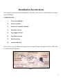
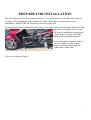
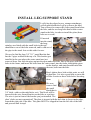
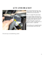
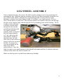
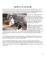
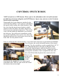
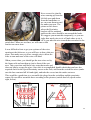
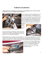
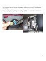
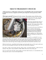
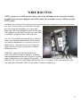
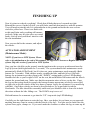
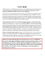
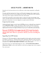
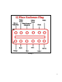
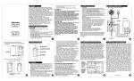
Installation Manual
Burgman 400
Version 1
Copyright 2011, Pete Giarrusso, Inc.
D/B/A Chopper Design Services
All Rights Reserved
2
Table of Contents
INTRODUCTION .................................................................................... 4
WARRANTY ............................................................................................ 5
INSTALLATION INSTRUCTIONS ...................................................... 6
COMPONENTS: .................................................................................................... 6
1)
2)
3)
4)
5)
6)
7)
8)
Control Switch Box...................................................................................................... 6
Linear Actuator ........................................................................................................... 6
On-board Computer Module ....................................................................................... 6
Proximity Sensor ......................................................................................................... 6
Leg Support Stand ....................................................................................................... 6
Leg/Wheel System ........................................................................................................ 6
Hardware Bag.............................................................................................................. 6
Actuator Bracket.......................................................................................................... 6
PREPARE FOR INSTALLATION ...................................................................... 7
INSTALL LEG SUPPORT STAND ..................................................................... 8
ACTUATOR BRACKET .................................................................................... 10
LEG/WHEEL ASSEMBLY ................................................................................ 11
CONTROL SWITCH BOX ................................................................................. 13
WIRING HARNESS ............................................................................................ 15
INITIAL SYSTEM TEST .................................................................................... 17
MOUNT PROXIMITY SWITCH ....................................................................... 18
FINISHING UP ..................................................................................................... 21
ACTUATOR ADJUSTMENT (Maintenance Mode) ....................................................... 21
TEST RIDE ........................................................................................................... 23
LEGUP LITE - ADDENDUM ............................................................................. 25
ILLUSTRATIONS ............................................................................................... 26
Wiring 1 ............................................................................................................................ 26
Wiring 2 ............................................................................................................................ 26
Wiring 3 ............................................................................................................................ 27
PARTS LIST ........................................................................................... 28
3
Introduction
This manual covers installation of the LegUp LandinGear system by Chopper Design Services.
This system should only be installed by a qualified technician, or those with above average
mechanical skills. If you are not SURE that you can perform this installation, please contact us
and we will help you find a qualified shop to assist you.
If you have been looking for a system that will keep your feet on the pegs, this is NOT the
system for you! On the other hand, if a system that will relieve you of the weight of the bike
and help you avoid balance problems as you approach a stop, LegUp is what you need.
Improper installation will void your warranty, so please be very careful!
Thanks for choosing LegUp!
4
Warranty
Chopper Design Services warrants the LegUp system for a period of one year from date of
purchase. This warranty covers replacement parts and/or manufacturer defects. Incidental
damages or costs are the responsibility of the purchaser.
Defective parts are to be returned to Chopper Design at the address below. Purchaser must
contact Chopper Design to receive a Return Material Authorization, prior to returning defective
parts to Chopper Design.
Abuse, improper installation or use, collisions or accidents, are not covered under this warranty.
Replacement parts for this type of damage are available through Chopper Design.
Users of the LegUp system agree that Chopper Design is NOT responsible for personal injuries
or damage to property arising from the use of the system. While we believe this system to be
safe and reliable, the user is advised that use of LegUp is done so at the users’ own risk. Use of
the system implies agreement to the above statements. If you can’t agree with the above,
Chopper Design and its dealers would be happy to refund your full purchase price, before you
use the LegUp System.
Chopper Design Services
1365 Bennett Dr #101
Longwood, FL 32750
407-834-5007
[email protected]
5
Installation Instructions
The LegUp® system has many components. Pleased be sure you have them all before starting
your installation.
COMPONENTS:
1)
Control Switch Box
2)
Linear Actuator
3)
On-board Computer Module
4)
Proximity Sensor
5)
Leg Support Stand
6)
Leg/Wheel System
7)
Hardware Bag
8)
Actuator Bracket
If you believe you are missing any parts, please contact Chopper Design at 407-834-5007, and
we will rectify the situation.
Figure 1
6
PREPARE FOR INSTALLATION
Place the motorcycle on an acceptable bike lift. You will need to keep the bike on its wheels
for most of the installation, and jack the rear wheel off the lift for some portion of the
installation. Make SURE the motorcycle is secure on the lift!
In preparation for the installation, please remove the side covers on the left side of the bike, and
the bottom skid plate. These come
off with a combination of push-pins,
screws & press-fit parts. The bike
should look something like this.
If you don’t have a manual, and are
not sure of how to remove these,
please seek help from qualified
technicians for this bike.
We are now ready to begin!
7
INSTALL LEG SUPPORT STAND
LegUp has developed a new, stronger attachment
system which holds the LegUp system to the bike!
You will need to remove the center stand from below
the bike, and the two long bolts that bolt the centerstand to the bike, in order to install the plate (these
bolts are re-used).
If inserted
into the stand,
the long
stainless steel shaft with the small bolts in the end
should have one of the bolts removed, and be slid out of
the pipe in the stand. Just set this aside for now.
We need to find the long 3/8” X 1” metal Bracket that
has the 2 pipes welded to the top of it. This bracket gets
installed in the spot where the center stand was just
removed from. Just slide the pipes up into the spots under the bike, line up the pipes with the
holes in the frame, and insert the bolts from the center stand, into the frame, through the pipes
on the bracket, and start them threaded into
the nuts, built onto the bike.
Don’t tighten these bolts at this point, we will
do that later. It is also a good idea to put a dab
of Blue Loctite on these bolts before inserting
them.
We next
want to find
the small
block that is
3/8” thick, with two threaded holes on it. This block will be
inserted in the wire-formed bracket on the bike as seen here.
The wire is just in front of the bracket you just installed. The
plate’s holes are not symmetrical! The plate is inserted with the hole that is closest to the edge,
toward the right side of the bike. This plate MUST be slipped in from the left side of the bike
and pressed until it stops!
8
Next we need to find the main attachment plate. It is the piece that has the big round pipe
welded on the end; the one you removed the stainless shaft from earlier! Offer the plate up to
the bike to be attached to the bracket that was bolted in place of the center stand.
This is bolted with the pipe offset toward the ceiling,
and the four holes get 3/8” Bolts. The outer holes get
3/8”X1” bolts with washers and the inside holes get
3/8”X3/4” bolts with lock washers.
Start all the bolts but leave them very loose for now.
The next step is to find 2 ¼-20 bolts with lock
washers, and 2 chrome spacers. We will line these
bolts up with the front of the plate you just installed
and the plate we threaded in to the wire form on the
frame.
Using a bit of Blue Loctite on the bolts, run
them through the hole in the big plate, through
a Chrome spacer, and start threading into the
plate in the wire form, as shown here.
Again, leave these loose for now, as we will
be tightening everything in a specific
sequence.
Now we can tighten the two center 3/8” bolts
(but NOT the outer two yet), then the two
front bolts that run through the spacers.
Next remove the two outside bolts so you can
tighten the bolts that run through the center
stand mounts on the frame. Now reinstall the
outside bolts, and tighten them.
You shgo0uld now have a plate attached to the bike that is very strong, and won’t move when
you tug on it; Give it a try!
We can move on to the Actuator Bracket!
9
ACTUATOR BRACKET
The actuator bracket mounts to the
vehicle on the Left side, under what
would be the rear footrest area.
There is a single bolt on the frame
(see arrow). Remove this bolt; line
the actuator bracket up as show, and
thread the replacement hex head bolt
through the plate and back into the
threads in the frame. Loctite is in
order here, and be careful not to over
tighten as this is a small bolt.
This bracket gets it strength from the
extra mount that transfer the load
The next step is to mount the leg system!
10
LEG/WHEEL ASSEMBLY
If not completed already, first remove the bolts from the stainless steel rod in preparation for
mounting the legs. With help from an assistant, slide the Leg/Wheel Assembly around the rear
tire (careful of the finish!), and align the Leg Mounting Points (Vertical Flat steel with
Bushings) with the slots in the Support Stand. If available a very small amount of ‘Never
Seize’ on the shaft is in order here. Then start the stainless steel shaft in from one side through
the tube on the support stand, and through the first leg mounting point and its bushing. The fit
is tight, so take your time.
Carefully work the shaft
through the tube and the
second leg mounting point.
The shaft is inserted
properly when it is inserted
just past (approximately
1/8”) the end of the tube.
This distance should be
about the same on both
sides, but it is not critical as
long as both sides are inside
the tube. If you need to,
you can tap lightly on the
shaft (brass drift is
preferred here). Once the
shaft is in place, use a small amount of blue thread locker and install the (2) chrome bolts and
washers on the end of the shaft to finish it off.
Make sure the legs move up and down without any binding!
11
MOUNT ACTUATOR
Remove the axles from both the upper and lower actuator mounts (aluminum blocks - one on
the legs and one on the upper actuator mount), and set them aside. Align the actuator, motor
side (big end) down as shown, with the hole in the upper actuator mount. Reinstall the axle bolt
on the upper actuator mount first. Use just a touch of thread locker on the threads.
With someone supporting the wheel
assembly, raise the legs until the
bottom hole in the actuator is aligned
with the lower actuator mount Install
the axle bolt you just removed, into
this mount, through the actuator and
the other side of the mount (Some
wiggling may be required!).
NOTE: If the actuator is too short to
reach the other mount you may have
to lengthen it using the system.
Temporarily plug the wiring harness
into the bike, and follow the direction
for ‘Maintenance Mode’ in the
‘Initial System Test’ section below. Using what would be the left button on the switch box, just
add a small amount of length to the actuator so you can align the mounts, then turn the bike
back off.
At this point you need to make sure that the mounts are in alignment and the actuator is not in
any sort of bind! On this bike, care must be taken that the actuator does not rub on the chrome
bolt at the end of the shaft. It is tight, but it should clear!
The mounts should be tightened at the factory. If need be readjust the actuator mounts in
whatever position is the best with the actuator in its mounts. If needed, mark the mounts with a
Sharpie, remove the actuator, tighten the mounts and reinstall the actuator. Make sure the axles
slide in easily and there is no bind at all. MAKE SURE there is no bind or the actuator will fail
prematurely!
12
CONTROL SWITCH BOX
NOTE: If you have a LITE System, Please refer to the addendum at the end of this manual,
for differences between a Regular and LITE Harness! Ignore any reference to the Proximity
Sensor and its mounting!
Disassemble the 8-pin connector attached to the
switch housing and the 3 pin connector attached to
the speed sensor (yellow on a black bracket). Run
the wire from the speed sensor bracket (which
mounts on the left fork by the brake) up the left
fork area to join with the switch wires. The switch
wires will run inside the handlebar cover down to
the fork area. You will need to install the switch
box on the handlebar, then run the wires down the
handlebar and meet the speed sensor wires near the
front fork. See the pictures below.
First we will mount the switch housing, so we know how much wire to put inside the handlebar
cover. Remove the stock bolt in the bottom of the switch
housing. Take the switchbox, run the supplied bolt (1/4” X
3.25”) through the hole in the back of the plate, then
through the supplied spacer and into the hole you just
removed the stock bolt from (Loctite). Tighten the bolt as
you align the switchbox. Once completed, the box and
wires should look like the photo above and to the left.
Now we can
run the wires
from the
switch
housing into the handlebar cover and forward
toward the forks. Pull any extra slack out toward
the bottom, but not too tight!
13
Now we need to join the
wires running up from the
left fork area and down
from the handlebars so
we can route them toward
the under seat area. The
picture at left shows
where the Proximity
bracket will be mounted,
and how the wires should be run around the brake.
We suggest you mount this temporarily, so you can
judge how much wire to tie off and where to tie it
off as you take this wire toward those attached to the
switch box! When we test later, we will remove this
bracket one more time.
It was difficult at best to get you a picture of the wires
meeting at the fork area, so you will have to brave this one
alone. Just make sure you leave enough wire to allow the
forks to turn and none of the wires will bind.
When you are done, you should get the two wires out by
the frame rails and run them to just in front of the seat
area. Take your time and find a wire route that works and
does not bind or scrape the wires. Once this is accomplished, double check that you have the
required slack for the Speed/Proximity sensor on the fork, and from the switch box wires (make
sure the bars can turn full left and right), and take the excess into the under seat area.
This would be a good time to re-assemble the plugs from the switchbox and the proximity
sensor. Be careful to assemble these according to the pictures (switch box left, speed sensor
right, below).
14
WIRING HARNESS
NOTE: If you have a LITE System, Please refer to the addendum at the end of this manual,
for differences between a Regular and LITE Harness!
The next step is to route the wiring harness. The
harness and the plugs are routed mostly under
the cover in front of the seat. We already ran the
wires from the handlebar switch and the speed
sensor. The actuator wire should be run as show
at left, culminating in the plug landing in front
of the seat. Make sure to leave enough slack in
the wire to allow the actuator to lower the legs
completely without tugging on the wire here.
You also
need to
wire tie
this wire
away
from any moving parts on the swing arm!
Now take the harness and find the 12-place plug. This
Plugs into the Computer. Assuming all the connectors
are in front of the seat, find each plugs mate, they only
plug in one way, and plug them together.
What should be left is an Orange wire and a Black wire. These need to be connector to switched
12Volt power (orange wire, only powered when key is on) and ground (black wire to chassis
ground). We got our 12V from the wires that ran to the running lights on the left side toward
the back of the bike. We even increased the fuse in the fuse box by 5 Amps for this circuit. But
you can use any 12 volt switched source
you want. Our system draw under 5 amps,
so most circuits can handle this type of
load. Once completed, it should look
something like the picture at left (We
supply these plugs).
15
The left picture below is a close up of the wire we used to power the system; just behind the
yellow plug.
When everything is completed, most all the plugs should be tied down neatly and thd should
wind up under the computer as shown here to the right.
16
INITIAL SYSTEM TEST
NOTE: If you have a LITE System, Please refer to the addendum at the end of this manual,
for differences between a Regular and LITE system. Skip this section if you have a LITE
System.
Turn your key switch on. At this point, have a look at the yellow proximity sensor (it should be
dangling near the front forks somewhere. If it is still mounted, remove the caliper bolt to allow
it to dangle). The RED LED (ON The Sensor) Should Not Be Lit. Take a metal object
(screwdriver, wrench, etc.) and hold it on the flat face of the sensor (it has a circle embossed in
it). The LED should light up, and go out when you move the metal away. If not, check all your
connections.
Next, press the rightmost pushbutton and hold it for at least 3 seconds. One or both LEDs on the
switch panel should light up; we really don’t care which at this point. If this occurs, you are
doing well. If both LEDs are flashing (maintenance mode) you can skip the next step which is
to press both buttons until both LEDs flash.
Next press both buttons for just an instant! If everything is working, the bottom or yellow LED
on the switch box should flash, and the top LED should be out. The next step, and be careful
here, is to touch the left button for a split second. The legs should move down just a bit. Touch
the right button, and they should move up. With the bike on the lift, you have to be very
careful here!
If all of the above has occurred, raise the legs. Press and hold the right button until it stops, and
turn the ignition switch off!
The test is now complete. Let’s move on to mounting the Proximity Sensor.
17
MOUNT PROXIMITY SWITCH
NOTE: If you have a LITE System, Please refer to the addendum at the end of this manual,
for differences between a Regular and LITE system. Skip this section if you have a LITE
System.
This step is crucial!! Understand it before starting. The proximity sensor tells the system
how fast the bike is traveling. The proximity sensor mounts to the lower front fork. The sensor
will ultimately be mounted 5MM
from the rotor bolts.
On the front of the left fork, there are
two bolts that hold the brake caliper
to the bike. The bottom of these bolts
is used to mount our bracket.
This bracket with sensor should be in
the area of the left fork already.
Remove the bolt, put it through the
mounting bracket and reinstall the
bolt with a bit of Loctite. Do Not
tighten completely yet. The bracket
keeps from rotating by leaning on the
fork leg.
It would be very helpful if you can
jack the front wheel of the ground or lift for this operation. The idea here is to have the yellow
proximity bracket line up with the rotor bolts and be placed no more than 5MM away from
them as they rotate! The picture shows the bracket perfectly aligned and also shows how we
tied the wire to the fork leg, before routing it up the brake line toward the switch box wires.
With a bit of Loctite, reinstall the bolt leaving it just barely tight for now. We want to make sure
the wires will run properly and can be tied off to the brake line to disappear!
Now have a look at the bracket and the yellow sensor (red LED should be visible from the
bottom). The yellow sensor should be within 5MM of the rotor bolts as they spin.
Now we need to have the bike on the ground or the front wheel raised, so we can make the rotor
bolts pass the sensor, to test it and its placement.
18
Turn the ignition switch to the on position. The LED may or may not be on. What we are
looking for here is for the LED to light as a rotor bolt passes close to the sensor and to go out as
the bolt passes by. Have someone watch the LED as you roll the wheel, or the bike, back and
forth making the bolts pass close to the sensor.
Once you feel you have the right place, tighten the bolt in the bracket down securely, and test
again!
If this is not happening, you may need to get the sensor a bit closer to the bolts (5MM is a very
small distance!). If you have to move the sensor closer, you may have to bend or adjust the
angle of the bracket.
No matter what you need to do, you MUST make sure that as the wheel turns, the light works as
described above! The automatic retraction of the legs as well as their deployment RELIES on
this sensor being placed perfectly!
Once satisfied with the mount, skip down to the wire routing instructions below.
19
WIRE ROUTING
NOTE: If you have a LITE System, Please refer to the addendum at the end of this manual,
for differences between a Regular and LITE system. The Proximity sensor is NOT part of the
LITE system!
Guide the wires from the Proximity bracket up the brake line, and attach it to the line with wire
ties. Once routed, make sure both this wire and
the wires from the handlebars are secure and
allow full lock of the handlebars both left & right!
Take whatever extra slack from the two wires that
is available, and pull it back to the seat area!
Use wire ties to make sure that all wires will stay
where you put them and that they will not come
on contact with that moves. Loop any excess as
shown above. Keep the excess wire clean and
make sure the seat goes up and down without
hitting any wires.
With help, support the bike and turn on the
LegUp system (see owner’s manual). It should
start in maintenance mode, but if it doesn’t, please
enter maintenance mode (again in the manual). Now carefully, lower and raise the legs and
make sure the wires are not binding and that they clear everything! Raise the legs most of the
way and turn off the bike. Now we are ready to button everything up.
20
FINISHING UP
Now it is time to recheck everything! Check that all bolts that were loosened are tight.
Reinstall the covers. On the left side, you will find a small tab that interferes with the actuator.
You will need to trim this tab. It is perpendicular to the ground and inside the area we have
circled in yellow here. There is no down side
to this small trim and everything still mounts
perfectly. Make sure all your wires are routed
neatly, tied off nicely and don’t interfere with
the seat installation.
Now you can dial in the actuator, and adjust
the wheels.
ACTUATOR ADJUSTMENT
(Maintenance Mode)
NOTE: If you have a LITE System, Please
refer to the addendum at the end of this manual, for differences between a Regular and LITE
system. Skip this section if you have a LITE System.
Once you have the bike on the ground, turn the ignition to the accessory position and start the
LegUp System (hold right button for 3 seconds). The system should enter maintenance mode
automatically (Both LEDs Flash), but if it does not, enter maintenance mode manually (Both
buttons for 3 seconds). With a helper nearby, straddle the bike, and hold it level. Hit both
buttons for an instant to get the system in the “DOWN” setting mode (yellow LED flashing).
Straddle the bike so your weight is NOT on the seat, hit and hold the left button until the wheels
contact the ground and stop. Make sure that the suspension raises a bit as you do this. If not,
the legs are not going down far enough, the bottom actuator mount may need to be moved left
or right a bit to get the wheels all the way down (Contact LegUp for assistance if you need help
with this). Once these wheels are down as described above, try to put both feet on the
floorboards. The bike should be reasonably stable and you should be able to lean a bit in both
directions without the bike falling over. The DOWN stop is now set!
Hit both buttons for a moment to get into the “UP” stop mode (top LED blinking).
Carefully use the right button to raise the legs. Have your helper let you know as you approach
anything that may come in contact with the wheels or the legs. You also need to make sure the
system clears pipes, clamps etc. If you can’t make the clearance to allow the legs to come up all
21
the way, you can set the up stop just below whatever is interfering (if not, you will likely set up
a permanent rattle!) Hit both buttons when complete, and you will be done with these
adjustment.
Now press the left button and the legs should lower. Hit it again and the legs should retract. If
you are satisfied with these limits, you have successfully installed the LegUp System. Time for
a test ride!
22
TEST RIDE
NOTE: If you have a LITE System, Please refer to the addendum at the end of this manual,
for differences between a Regular and LITE system. Deployment and Retraction of the
wheels is COMPLETELY MANUAL if you have a LITE System.
Get the bike to a clear paved mostly level area where you can test ride it. Start the bike, turn on
the LegUp system and lower the legs. The first test should be done in a straight line. Put the
bike in gear and slowly accelerate. You may notice that the bike tends to want to steer a small
amount left or right. This is normal unless it is severe. Once underway, the top LED should
flash at around 6 MPH, meaning the legs are retracting. You can lean on one wheel or the other
as you leave to reduce any darting the system may be giving you.
Assuming the legs are retracted, you should try to deploy the wheels. As you come to a stop,
the Green LED should be on. As you slow down (almost stopped), the Yellow LED should
illuminate at the proper speed. Once it does (sometimes hard to see), hit the left button and put
your feet down near the ground. The top LED should flash and you should soon feel the wheels
deploying underneath you! Make sure you are ready to balance the bike! Uneven ground or
lack of familiarity could make the bike want to lean one way or the other. With your feet ready
to balance the bike, this should be no big deal. The slower you are going when deploying the
wheels, the smoother the transition will be from wheels up to wheels down. Practice these
maneuvers until you are comfortable with the wheel adjustments and the system operation.
SEMI-AUTOMATIC DEPLOYMENT: Another way to deploy the legs is to hit the left button
while you are running at any speed over 10MPH with the wheels up. The bottom or yellow
LED should start to flash. When you slow down to around 8MPH the wheels will start to deploy
(see the red/green flash on top LED). Again prepare to put your feet down.
NOTE: The bottom LED Should not be LIT if the legs are up over 10MPH! In
the event it is, the wheels will deploy instantly if you try to set them as above; this
is dangerous! You MUST re-visit the sections on testing the proximity sensor.
You should always be aware that this light should NOT be on if you are traveling
at speed, and ‘Arming’ the system for deployment should only be attempted if the
lower LED is Not Lit! Please see the User Manual for more information on
Proximity Sensor Failure!
23
The next thing to try is to make a turn right after a dead stop with the wheels down. As soon as
you start the bike moving, try a left or right turn immediately by leaning into that turn. You
may find that you have to nudge the bike a little bit more than usual to get the bike to lean, and
you won’t be able to lean as far as you can with the wheels up. Once into the turn, accelerating
will raise the wheels. You will hardly notice the wheels coming up unless you see the top LED
blinking!
The next thing to try is slow speed maneuvering with the wheels lowered. In a straight line on
level ground, you should be able to keep your feet on the floorboards and move the bike
forward at very slow speeds (simulate stop and go traffic). I like keeping my feet near the
ground during these maneuvers! You can also try small ‘Trike’ turns; keeping the bike upright
at slow speed and making turns as you would in a parking lot. Be aware that if you get over the
speed that the legs come up, they will!!! Another thing I like to do is donuts. Start out slow,
lean the bike left or right, and make circles at very slow speeds (throttle on, rear brake on,
clutch slipping… you know like the cops do!). This helps you get familiar with the wheels
being on the springs and allowing a lean angle! Practice, practice, practice!! Enjoy your
LegUp System!
24
LEGUP LITE - ADDENDUM
If you have a Lite System, there are a few differences in the wiring compared to our Regular
system.
The plugs and their locations don’t change at all! Instead of plugging in the computer to the
twelve pin plug, the Relay-Pack gets plugged into this plug. The Relay-Pack will be attached
with Velcro as the computer would have been in the same location.
On the LITE system there is no proximity sensor, so ignore the testing and mounting of this
sensor, and realize that the three pin plug will be left without a mating connector. We keep this
plug in the wiring harness in case you upgrade to a regular system in the future.
Using Your Lite System:
Unlike our Regular System, you don’t turn the LITE system on, or adjust the legs as described
in the ‘Maintenance Mode’ section of the manual. When you turn your bike on, the LITE
system is ready to go! Press and hold the left button to lower the wheels, press and hold the
right button to raise them. No lights will flash; it is up to you to control the system manually!
Please use EXTREME Caution when using the LITE System! Keeping the
wheels lowered at speeds over 9MPH can be dangerous. Since the system is
manual, please don’t allow its’ operation to distract you from controlling the
vehicle!
Upgrading Your LITE System:
If you have a LITE System and have chosen to upgrade it to the regular system, there are just a
few things you need to do. Unplug the Relay-Pack, and plug the computer in where the RelayPack was attached. Run the wire for the proximity bracket and plug it in, test it, and mount it, as
described in the ‘MOUNT PROXIMITY SWITCH’ section of this manual.
Once the new pieces are attached and plugged in, refer to ‘ACTUATOR ADJUSTMENT
(Maintenance Mode)’, earlier in this manual to set the lower and upper stops for the computer.
That’s all it takes!
25
ILLUSTRATIONS
Wiring 1
There are three different types of actuators with three different wiring configurations. Refer to the notes
at the bottom of the pictures above so you can match your actuator with its wiring scheme!
Wiring 2
26
Wiring 3
27
PARTS LIST
(4) 3/8-16 X 1” Cad Bolts w/ Lock Washers (Plate to hangers)
(2) 5/16 – 18 X 1 1/2” Cad Bolts w/Lock Washers (Cross Strap)
(1) Handlebar Spacer cut to 7/16” (Switch Box)
(1) 10-32 X 1 5/16” Chrome Allen (Switch Box)
(1) M5 X 60 mm Allen (Switch Box)
(1) M6 X 1.0 X 18 mm Hex Bolt (Upper Actuator Bracket)
28