1
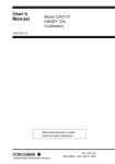
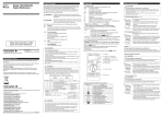
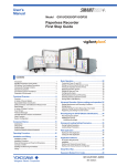
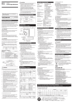
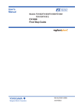
IM 04L24B01-01EN FW1000 User’ s Manual Safety Precautions and Installation Guide Introduction Thank you for purchasing the FW1000 (FW). This manual describes the safty precautions and installation and wiring procedures of the FW1000. Download the software (DAQSTANDARD) and electronic manuals from the YOKOGAWA website. (See IM 04L24B01-66EN.) Except for the following specifications, the FW1000 is equivalent to the FX1000. For details on how to handle the FW1000, see the relevant FX1000 manuals . When you read these manuals, read “FX1000” as “FW1000.” For FW1000 topics such as the package contents, safety precautions, and detailed handling procedures, see the electronic manuals. Specifications Different from the FX1000 • The following options are not available. Optional code Description /A1 Alarm output 2 points (C-contact) /A2 Alarm output 4 points (C-contact) /A3 Alarm output 6 points (C-contact) /A4A Alarm output 12 points (A-contact) /C3 RS-422A/485 interface /P1 24 VDC/AC power supply /TPS2 24VDC transmitter power supply (2 loops) /TPS4 24VDC transmitter power suply (4 loops) • This product is exempt from CE marking. • Specifications for Power Monitor (/PWR1 option) Rated input current 5A Current Range 5A Allowable Input Current Wiring System 6A 2 Input (AC) Rated Power Input Measuring Range 120V/5A 500W -600 to 600W 240V/5A 1000W -1200 to 1200W Single-phase three-wire system 200V/5A 1000W -1200 to 1200W Three-phase three-wire system 120V/5A 1000W -1200 to 1200W 240V/5A 2000W -2400 to 2400W Measurement accuracy Measurement element Measurement accuracy Active power ± 0.5% of Range voltage ± 0.5% of Range current ± 0.5% of Range 1. Safety Precautions The following safety symbols are used on the product and in this manual. WARNING CAUTION • YOKOGAWA makes no warranties regarding the product except those stated in the WARRANTY that is provided separately. • YOKOGAWA assumes no liability to any party for any loss or damage, direct or indirect, caused by the user or any unpredictable defect of the product. * Measurement category II (CAT II) applies to measuring circuits connected to low voltage installation, and electrical instruments supplied with power from fixed equipment such as electric switchboards. • This instrument is an EN61326-1 (EMC standard) class A instrument (for use in commercial, industrial, or business environments). • The general safety precautions described here must be observed during all phases of operation. If the FW is used in a manner not described in this manual, the FW safety features may be impaired. Yokogawa Electric Corporation assumes no liability for the customer’s failure to comply with these requirements. • The FW is designed for indoor use. n About This Manual • Please pass this manual to the end user. We also ask you to store this manual in a safe place. • Read this manual thoroughly and have a clear understanding of the product before operation. • This manual explains the functions of the product. It does not guarantee that the product will suit a particular purpose of the user. n Precautions Related to the Protection, Safety, and Alteration of the Product • For the protection and safe use of the product and the system in which this product is incorporated, be sure to follow the instructions and precautions on safety that are stated in this manual whenever you handle the product. Take special note that if you handle the product in a manner that violates these instructions, the protection functionality of the product may be damaged or impaired. In such cases, YOKOGAWA does not guarantee the quality, performance, function, and safety of product. • When installing protection and/or safety circuits such as lightning protection devices and equipment for the product and control system or designing or installing separate protection and/or safety circuits for fool-proof design and fail-safe design of the processes and lines that use the product and the control system, the user should implement these using additional devices and equipment. • If you are replacing parts or consumable items of the product, make sure to use parts specified by YOKOGAWA. • This product is not designed or manufactured to be used in critical applications that directly affect or threaten human lives. Such applications include nuclear power equipment, devices using radioactivity, railway facilities, aviation equipment, air navigation facilities, aviation facilities, and medical equipment. If so used, it is the user’s responsibility to include in the system additional equipment and devices that ensure personnel safety. • Do not modify this product. CrestFactor Rated input power and measuring range Single-phase two-wire system n Exemption from Responsibility • This instrument conforms to IEC safety class I (provided with terminal for protective grounding), Installation Category II, and EN61326-1 (EMC standard), Measurement Category II (CAT II)*. 1st Edition : Mar. 2015 Rated Current n Safety Precautions Calls attention to actions or conditions that could cause serious or fatal injury to the user, and indicates precautions that should be taken to prevent such occurrences. Calls attention to actions or conditions that could cause injury to the user or damage to the instrument or property and indicates precautions that should be taken to prevent such occurrences. “Handle with care.” To avoid injury and damage to the instrument, the operator must refer to the explanation in the manual. Protective ground terminal Alternating current ON(power) Functional ground terminal Direct current OFF(power) l Use the Correct Power Supply Ensure that the source voltage matches the voltage of the power supply before turning ON the power. WARNING l Use the Correct Power Cord and Plug To prevent electric shock or fire, be sure to use the power cord supplied by Yokogawa. The main power plug must be plugged into an outlet with a protective earth terminal. Do not disable this protection by using an extension cord without protective earth grounding. The power cord is designed for use with this instrument. Do not use the power cord with other instruments. l Connect the Protective Grounding Terminal Make sure to connect the protective grounding to prevent electric shock before turning ON the power. The provided power cord are three prong type power cord. Connect the power cord to a properly grounded three-prong outlet. l Do Not Impair the Protective Grounding Never cut off the internal or external protective grounding wire. Doing so invalidates the protective functions of the instrument and poses a potential shock hazard. l Do Not Operate with Defective Protective Grounding Do not operate the instrument if the protective grounding might be defective. Also, make sure to check them before operation. l Do Not Operate in an Explosive Atmosphere Do not operate the instrument in the presence of flammable liquids or vapors. Operation in such an environment constitutes a safety hazard. Prolonged use in a highly dense corrosive gas (H2S, SOx, etc.) will cause a malfunction. l Do Not Remove Covers The cover should be removed by YOKOGAWA’s qualified personnel only. Opening the cover is dangerous, because some areas inside the instrument have high voltages. l Ground the Instrument before Making External Connections Connect the protective grounding before connecting to the item under measurement or control unit. l Damage to the Protection Operating the instrument in a manner not described in this manual may damage the instrument’s protection. Note Identifies important information required to operate the instrument. CAUTION This instrument is a Class A product. Operation of this instrument in a residential area may cause radio interference, in which case the user is required to take appropriate measures to correct the interference. n External Dimensions Unit: mm (approx. inch) If not specified, the tolerance is ±3%. However, in cases of less than 10mm, the tolerance is ±0.3 mm. n Model and Suffix Codes Model code Suffix code Optional code Description FW1002 2ch, Shortest measurement interval: 125ms FW1004 4ch, Shortest measurement interval: 125ms FW1006 6ch, Shortest measurement interval: 1s FW1012 12ch, Shortest measurement interval: 1s External storage -0 medium slot -4 Without CF card slot and medium (Note) Language With CF card slot and medium (512MB) -2 Withstanding voltage between measuring input terminals Handle 184.0 (7.24) 144.0 (5.67) English/Japanese/German/French/Chinese/Italian/ Spanish/Portuguese/Russian/Korean deg F and DST -H 1000 VAC (50/60 Hz), 1 min -L 400 VAC (50/60 Hz), 1 min Power cord -D Power cord UL/CSA standard -F Power cord VDE standard -H Power cord GB standard -N Power cord NBR standard -Q Power cord BS standard -R Options 189.3 (7.45) Installation Guide Power cord AS standard /C2 RS-232 interface /C7 Ethernet interface /F1 FAIL/Status output /M1 Mathematical functions (including Report functions) /N2 3 leg isolated RTD*1 /N3F Extended input type (without Pt1000) /R1 Remote control 8 points*2 /USB1 USB interface (1 port) /PM1 Pulse input 3 points, Remote control 5 points (including Mathematical functions)*3 /CC1 Calibration correction function /LG1 Log scale /PWR1 Power monitor (including Mathmatical functions)*4 Note: To load data, the FW must be equipped with a communication interface (/C2 or /C7 option) or the USB interface (/USB1 option.) *1 /N2 cannot be specified for FW1002 or FW1004. If /R1 is specified, /PM1 or /PWR1 cannot be specified. *2 *3 If /PM1 is specified, /M1, /R1, or /PWR1 cannot be specified. *4 If /PWR1 is specified, /F1, /R1, /PM1, or /M1 cannot be specified. 2. Installation n Installation Location Install the FW indoors in an environment that meets the following conditions: • Well-Ventilated Location To prevent overheating, install the FW in a well-ventilated location. • Minimal Mechanical Vibrations Install the FW in a location that has minimal mechanical vibrations. Installing the FW in a location that is subject to large levels of mechanical vibration will not only put added stress on its components, it may also impede ordinary measurement. • Level Location Install the FW in a level location so that it is not slanted to the left or the right. Note Condensation may form when moving the FW from an environment whose temperature or humidity is low to an environment whose temperature or humidity is high, or when there is a sudden change in temperature. Temperature or humidity changes may also result in thermocouple measurement errors. In these kinds of circumstances, let the FW adjust to the new environment for at least an hour before using it. Do not install the FW in the following places. • Outdoors • In Direct Sunlight or Near Heat Sources Install the FW in a place that is near room temperature (23°C) and that is not subject to large temperature fluctuations. Placing the FW in direct sunlight or near heat sources can cause adverse effects on the internal circuitry. • Where an Excessive Amount of Soot, Steam, Moisture, Dust, or Corrosive Gases Are Present Soot, steam, moisture, dust, and corrosive gases will adversely affect the FW. Avoid installing the FW in such locations. • Near Strong Magnetic Field Sources Do not bring magnets or instruments that produce electromagnetic fields close to the FW. Operating the FW near strong magnetic fields can cause measurement errors. • Where the Display Is Difficult to See The FW uses an LCD screen, so it is difficult to view the display from an extreme angle. Install the FW so that the user can view the display directly from the front. 3. Wiring n Input Signal Wiring To prevent electric shock while wiring, make sure that the power supply is turned off. WARNING l Applying a strong tension to the input and output signal cables connected to the FW may damage the cables or the FW terminals. To avoid applying tension directly to the terminals. CAUTION l To prevent fire, use signal cables with a temperature rating of 80°C or more. l Do not apply voltages that exceed the following values to the input terminals. Doing so may damage the FW. • Maximum input voltage: ±60 VDC • Maximum common mode voltage: ±60 VDC (under measurement category II conditions) l The FW is an installation category II product. Precautions to Be Taken While Wiring Take the following precautions when wiring the input signal cables. When using a screw terminal, we recommend that you use a crimp-on lug with an insulation sleeve (designed for 3 mm screws). Take measures to prevent noise from entering the measurement circuit. • Move the measurement circuit away from the power cable (power circuit) and ground circuit. • Ideally, the object being measured should not generate noise. However, if this is unavoidable, isolate the measurement circuit from the object. Also, ground the object being measured. • Shielded wires should be used to minimize the noise caused by electrostatic induction. Connect the shield to the ground terminal of the FW as necessary (make sure you are not grounding at two points). • To minimize noise caused by electromagnetic induction, twist the measurement circuit wires at short, equal intervals. • Make sure to earth ground the protective ground terminal through minimum resistance (less than 100 Ω). When using internal reference junction compensation on the thermocouple input, take measures to stabilize the temperature at the input terminal. • Always use the terminal cover. • Do not use thick wires which may cause large heat dissipation (we recommend a cross sectional area of 0.5 mm2 or less). • Make sure that the ambient temperature remains reasonably stable. Large temperature fluctuations can occur if a nearby fan turns on or off. Connecting the input wires in parallel with other devices can cause signal degradation, affecting all connected devices. If you need to make a parallel connection, consider the following points. • Turn the burnout detection function off. • Ground the instruments to the same point. • Do not turn other instruments on or off during operation. This can have adverse effects on the other instruments. • RTDs cannot be wired in parallel. IM 04L24B01-01EN page 1/2 CH2 • FAIL Output Terminal and Memory End Output Terminal (/F1) CH1 Output format: Contact rating: Relay contact 250 VAC (50/60 Hz)/3 A, FAIL output NO C NC 250 VDC/0.1 A (load resistance) (/F1) During normal Withstand voltage: 1600 VAC (50/60 Hz) for one operation minute (between output terminals and the ground Memory end NO C NC terminal) output (/F1) During normal Input terminal block of the FW1002 +/A –/B CH4 CH3 CH2 /b CH1 operation Input terminal block of the FW1004 CH5 CH4 CH3 CH2 • Relay contact input (voltage-free contact) Contact open at 200 Ω or less Contact closed at 100 kΩ or greater /b CH1 Input terminal block of the FW1006 +/A –/B CH6 CH5 CH4 CH3 CH2 • Transistor input (open collector) On voltage: 0.5 V or less (30 mADC) Leakage current when turned off: 0.25 mA or less /b CH1 Input terminal block of the FW1012 CH12 CH11 CH10 CH9 CH7 For TC input, use shielded compensating lead wires for wiring. For RTD input, lead wire resistance per wire of 10 Ω or less. Make the resistances of the three wires equal. For DCA input, example: for 4 to 20 mA input, use a shunt resistor of 250 Ω ± 0.1%. Note Optional Terminal Wiring n l To prevent electric shock while wiring, make sure that the power supply is turned off. l If a voltage of more than 30 VAC or 60 VDC is to be applied to the WARNING output terminals, use ring-tongue crimp-on lugs with insulation sleeves on all terminals to prevent the signal cables from slipping out when the screws become loose. Furthermore, use double-insulated cables (dielectric strength of 3000 VAC or more) for the signal cables on which a voltage of 30 VAC or 60 VDC or more is to be applied. For all other signal cables, use basic insulated cables (dielectric strength of 1500 VAC). To prevent electric shock, attach the terminal cover after wiring and make sure not to touch the terminals. l Use the following circuit voltages for the connection to the FAIL/ status output terminal. • When the connection is to Mains Circuits (primary power supply circuits): 150 V or less CAUTION • When the connection is to circuits derived from Mains Circuits (secondary power supply circuits): 250 V or less (Keep the Mains Circuit voltage at 300 V or less, and use an isolation transformer.) l To prevent fire, use signal cables with a temperature rating of 70°C or more. l Applying a strong tension to the input and output signal cables connected to the FW may damage the cables or the FW terminals. To avoid applying tension directly to the terminals. Precautions to Be Taken While Wiring We recommend that you use crimp-on lugs (designed for 3 mm screws) with insulation sleeves to connect to the optional terminals. The following figures show the terminal positions for each option when only that option is installed. Even if you have installed a number of options, the individual terminal positions of the options do not change. • Relay contact input (voltage-free contact) Contact open at 200 Ω or less Contact closed at 100 kΩ or greater • Transistor input (open collector) On voltage: 0.5 V or less (30 mADC) Leakage current when turned off: 0.25 mA or less L H L Pulse input H 5 4 3 2 Remote control input FAIL /R1 1L 1S P3 P2 P1 Current input Current input Voltage input 8 7 6 5 4 3 2 Remote control input L P3 P2 P1 部件名称 1S 1L 2S 2L K k CT L l 有毒有害物质或元素 显示器 (LCD) 印刷电路板 内部接线材料 Fuse U u V V v v P1 P0 P2 外壳 / 机箱 塑料 金属 电源 操作键 U VT u 标准附件 / 可选附件 Load 3L Fuse 3S 1L 1S P3 P2 P1 1S 1L 3S 3L U u V V v v 汞 (Hg) 镉 (Cd) 六价铬 (Cr6+) 多溴联苯 (PBB) 多溴二苯醚 (PBDB) N/A N/A N/A N/A N/A N/A N/A N/A N/A N/A N/A N/A N/A N/A N/A N/A N/A N/A N/A N/A N/A N/A N/A N/A N/A N/A N/A N/A N/A N/A N/A N/A N/A N/A N/A N/A N/A N/A N/A N/A 分流电阻 N/A N/A N/A N/A :表示该部件的所有均质材料中的有毒有害物质或元素的含量均低于 GB/T 26572 标准所规定 的限量要求。 N/A :表示该部件中至少有一种均质材料中的有毒有害物质或元素的含量超过 GB/T 26572 标准 所规定的限量要求。 CF 卡 R S T (A) (B) (C) K k CT L l 用于端子的 螺丝 铅 (Pb) 电源线 Power supply 1 2 3 K k CT L l This is an explanation for the product based on “Control of pollution caused by Electronic Information Products” in the People’s Republic of China. 产品中有毒有害物质或元素的名称及含量 环保使用期限 该标志为环境保护使用期限,根据 SJ/T11364,适用于在中国 ( 台湾、 香港、澳门除外 ) 销售的电子电气产品。只要遵守该产品的安全及 使用注意事项,从产品生产之日起至该标志所示年限内,不会因为 产品中的有害物质外泄或突变而导致环境污染或对人身财产产生重 大影响。 P1 P2 P3 U VT u Load Power cord n Do not connect an Ethernet cable whose plug does not comply with FCC specifications. If you do, the FW may malfunction. CAUTION Ethernet port Indicators • Connecting to the Power Measurement Terminal (/PWR1) Max. rated voltage: 300V, Max. rated current: 5A, Measurement category: CAT II l If you are not using a VT and a CT, do not ground the input circuit. l If you are wiring through conduits (metal tubes designed for wiring), install the CT (current transformer) inside a panel. CAUTION l Wire the voltage input and the current input within the same circuit. Make sure to follow the warnings below when wiring the power supply. Failure to do so may cause electric shock or damage to the instrument. l Before connecting the power cord, ensure that the source voltage matches the rated supply voltage of the FW and that it is within the maximum rated voltage range of the provided power WARNING cord. l Confirm that the power switch is OFF before connecting the power cord. l To prevent electric shock or fire, be sure to use the power cord supplied by YOKOGAWA. l Make sure to perform protective grounding to prevent electric shock. Connect the power cord of the desktop type to a threeprong power outlet with a protective ground terminal. l Do not use an extension cord without protective ground. Otherwise, the protection function will be compromised. l Make sure to earth ground the protective ground terminal through minimum resistance. Functional ground terminal Single-phase two-wire system Power switch Power inlet Power supply 1 2 1L 1S 1L K k CT L l 1S P2 P1 Use a power supply that meets the following conditions: Item Rated supply voltage Condition 100 to 240 VAC Allowable power supply voltage range 90 to 264 VAC Rated power supply frequency 1 C Memory end u Fuse NO C NC NO C NC 3L 3S 1S 50/60 Hz Allowable power supply frequency range 50/60 Hz ± 2% C /PWR1 H • Serial Communication Interface (/C2) 9-pin D-sub RS-232 connector • Connecting to the USB Port (/USB1) The USB port complies with USB revision 1.1. The USB port is installed on the FW’s front panel. • Connecting to the Ethernet Port (/C7) /F1 1 Internal circuit 5V Input format: Photocoupler isolation Shared common (L) Allowable input voltage: 30 VDC Withstand voltage: 1000 VDC for one minute between input terminals and the ground terminal U H 3S 1L Three-phase three-wire system RTD input terminals A and B are isolated on each channel. Terminal b is shorted internally across all channels. However, terminal b is also isolated on each channel on models with the /N2 option (3 leg isolated RTD). L 1 to 8 C 3L Input format: Photocoupler isolation Shared common (C) Allowable input voltage: 5 VDC 4. Protection of Environment Control of Pollution Caused by the Product n Power supply 1 N 2 K k CT L l Internal circuit 5V For a single-phase three-wire system, connect wires to the terminal block as follows. NO C NC NO C NC When the When power specified is turned off status occurs • Pulse Input Terminal (/PM1) /b /PM1 When a failure When power occurs is turned off Withstand voltage: 1000 VDC for one minute between input terminals and the ground terminal +/A –/B CH8 NO C NC • Remote Control Input Terminal (/R1) +/A –/B CH6 NO C NC Single-phase three-wire system V VT v Load P1 P2 Maximum power consumption 35 VA (100 V), 45 VA (240 V) Note Do not use a supply voltage of 132 to 180 VAC, as this may have adverse effects on the measurement accuracy. YOKOGAWA ELECTRIC CORPORATION Network Solutions Business Division 2-9-32, Naka-cho Musashino-shi, Tokyo 180-8750 JAPAN YOKOGAWA CORPORATION OF AMERICA Head office and for product sales 2 Dart Road, Newnan, Georgia 30265, USA YOKOGAWA EUROPE B.V. Headquarters Euroweg 2, 3825 HD Amersfoort, THE NETHERLANDS www.yokogawa.com/ns All Rights Reserved, Copyright © 2015 Yokogawa Electric Corporation IM 04L24B01-01EN page 2/2